EP1520756A2 - Renvoi de ceinture de sécurité pour véhicule automobile - Google Patents
Renvoi de ceinture de sécurité pour véhicule automobile Download PDFInfo
- Publication number
- EP1520756A2 EP1520756A2 EP04090364A EP04090364A EP1520756A2 EP 1520756 A2 EP1520756 A2 EP 1520756A2 EP 04090364 A EP04090364 A EP 04090364A EP 04090364 A EP04090364 A EP 04090364A EP 1520756 A2 EP1520756 A2 EP 1520756A2
- Authority
- EP
- European Patent Office
- Prior art keywords
- holding body
- belt
- gurtumlenkeinrichtung
- deflection
- edge
- Prior art date
- Legal status (The legal status is an assumption and is not a legal conclusion. Google has not performed a legal analysis and makes no representation as to the accuracy of the status listed.)
- Granted
Links
Images


Classifications
-
- B—PERFORMING OPERATIONS; TRANSPORTING
- B60—VEHICLES IN GENERAL
- B60R—VEHICLES, VEHICLE FITTINGS, OR VEHICLE PARTS, NOT OTHERWISE PROVIDED FOR
- B60R22/00—Safety belts or body harnesses in vehicles
- B60R22/18—Anchoring devices
-
- B—PERFORMING OPERATIONS; TRANSPORTING
- B60—VEHICLES IN GENERAL
- B60R—VEHICLES, VEHICLE FITTINGS, OR VEHICLE PARTS, NOT OTHERWISE PROVIDED FOR
- B60R22/00—Safety belts or body harnesses in vehicles
- B60R22/18—Anchoring devices
- B60R2022/1818—Belt guides
- B60R2022/1843—Belt guides comprising an elongated sleeve
Definitions
- the invention relates to a Gurtumlenk noticed for a safety belt of a motor vehicle.
- German laid-open specification DE 101 03 319 A1 discloses a belt deflection device described with an energy absorption unit.
- the safety belt deflected by the vehicle occupants so is on the Deflection exercised a considerable tensile force.
- the Energyabsorption unit designed such that they a Yielding of the seatbelt allowed; This happens concretely in the way that one Deflection element of the Gurtumlenk overlooked under deformation of the deflection holding holding elements is moved or moved so that it to a "Gurtvernostirung" comes for the vehicle occupants.
- To the described To allow energy absorption is the previously known Gurtumlenk issued multiple parts built up.
- the invention is based on the object, a Gurtumlenk issued for a Seat belt of a motor vehicle to specify a simple and thus has low cost construction and at the same time a high level of security for Ensures the vehicle occupants in the event of a vehicle accident.
- the one-piece Holding body has at least one holding point on which a deflecting element held becomes; the deflecting element forms a deflection axis around which the seatbelt of the Motor vehicle is deflected.
- the holding body is according to the invention beyond formed so that it forms a Gurtumlenkkante to which the belt of Motor vehicle once again, so in addition, is deflected.
- the deflection edge of the Holding body stands in this case to the deflection axis of the deflecting in an acute Angle.
- the holding body according to the invention moreover has at least one Attachment point, which is a rigid mounting of the holding body to the body of the Motor vehicle allows.
- a significant advantage of the Gurtumlenk adopted invention is to that this also in the case of a vehicle accident, a reliable "functioning" of Safety belt ensured; in particular a clamping or twisting or “Turning over" the seat belt on the deflecting the Gurtumlenk Republic can not occur.
- This is inventively achieved in that the Deflection element is held by the one-piece holding body, the rigid itself to the Body of the motor vehicle is mounted.
- a pivoting or twisting of the Deflection element relative to the body can in the inventive Gurtumlenk issued - in contrast, for example, to the pivotable Gurtumlenk achieved according to the aforementioned US Patent - thus not occur.
- Gurtumlenk for deflecting the seat belt two has separate "deflection", namely on the one hand, the deflection and on the other hand the deflection edge. Due to the arrangement of the deflection in one acute angle to the deflection axis of the deflection is always guaranteed that despite the rigid mounting of the holding body to the body and thus despite the - im Contrary to the cited US patent - not "trackable" alignment of the Deflection axis of the deflection always optimal alignment of the Seat belt to the vehicle occupant is present.
- the one-piece holding body has at least two spaced apart or "spaced” arranged attachment points on; the attachment points are thereby formed on the holding body such that the remaining area of the holding body - for example, the center area between the attachment points - after the Assembly of the holding body to the body at least partially a predetermined Distance from the body.
- at least two spaced attachment points a kind of "bridge” through the holding body educated.
- the middle bridge area which has a distance to the body forms thus absorbing a "deformation area" of the motor vehicle Y-direction energy can. If the Gurtumlenk issued example in the area of the B-pillar of a Motor vehicle mounted, it is usually in shoulder or Head height of the vehicle occupant.
- the yielding of the center of the one-piece holding body allows, as under deformation of the holding body of the Center area or middle bridge area can be pressed onto the body. By this deformation, kinetic energy is "transformed", so that the impact the head of the vehicle occupant is at least somewhat damped.
- Ensuring energy absorption is the middle range between the Attachment points preferably in the Y direction or in the body direction at least slightly deformable.
- the Gurtumlenkkante can be by a Longitudinal edge of an opening slot or a belt exit slot in the holding body form.
- This belt exit slot should - for the reasons mentioned - at least be crimped in his cooperating with the safety belt area to the friction between the seat belt and the Gurtumlenkkante as low as possible to keep.
- the acute angle between the Deflection axis of the deflecting element and the Gurtumlenkkante in the range between 20 ° and 70 ° since with such an angle selection a particularly good orientation of the Safety belt is ensured relative to the vehicle occupant.
- an angle range between 35 ° and 55 ° since such an angular range in the Most motor vehicle models an optimal relative position or orientation of the Seat belt ensures relative to the vehicle occupants.
- the sharp angle can For example, be about 45 °.
- the deflecting element can be particularly simple and thus advantageous for example by a rotatably mounted pulley be formed by means of a pin on the one piece trained holding body is attached.
- the pen can be act a metal pin, in particular a steel pin.
- the pen can be used, for example, in the Breakpoints also be rotatably mounted.
- the deflection element can also by be formed a deflection bar, which is integrally formed on the holding body.
- the deflecting element by a piece on the holding body trained, further deflection be realized.
- the disadvantage is a Deflection bar or another deflection in comparison to a rotatably mounted Pulley, however, in the sense that greater frictional forces on the seat belt be exercised, so that the ease of use is slightly lower than in the case of a rotatably mounted pulley, in which due to the rotatable mounting only one low friction occurs and thus a particularly easy deflection or movement of the Seat belt by the vehicle occupants is possible.
- the holding body additionally a Gurtein technologicalschlitz having, preferably parallel to the deflection axis of Deflection element is arranged.
- the seat belt is then replaced by the Gurtein technologicalschlitz introduced into the region of the holding body and the Gurtein technologicalschlitz directed to the deflecting element; from the deflecting the seat belt is in Direction deflected to Gurtumlenkkante.
- Gurtumlenkkante is the Seat belt then deflected in the direction of the vehicle occupant once more, so that the seat belt leaves the region of the holding body again.
- the one-piece holding body by a stamped and bent part, for example by a stamped and bent part made of sheet metal.
- a stamped and bent part made of sheet metal.
- the above-mentioned belt exit slot is preferably through Punching from the punched-bent part or formed from the sheet metal part.
- the Attachment points are then preferred by bending edge regions, and Although in the mounting direction towards the vehicle body, formed.
- the Gurtein manufacturedschlitz is preferably in the one-piece holding body stamped.
- the invention is also based on the object, a simple and inexpensive Method for producing a belt deflection device for a safety belt of a Motor vehicle specify that a simple and therefore inexpensive construction and at the same time a high degree of safety for the vehicle occupants guaranteed even in the event of a vehicle accident.
- This object is achieved by a method for producing a Gurtumlenk tone solved, in which a one-piece holding body by a sheet metal part is formed, in which in the middle region of the sheet metal part, a belt exit slot is stamped and / or attachment points by bending edge areas of the Sheet metal part are formed and / or a belt insertion slot in the one-piece Holding body is punched.
- FIG. 1 shows a safety belt device with a safety belt 1 for a vehicle occupant 2.
- the belt 1 is with his a belt end 11 on a Belt reel 3 rolled up.
- the belt reel 3 is in the bottom portion 81 of the vehicle body. 8 firmly connected to the body 8.
- the belt reel 3 has a torque generating mechanism on, which is biased in Gurtaufwickelides and the Seat belt 1 tightens.
- the belt reel 3 also has a Abwickelsperran let on which attempted, fast extract of Seat belt 1 and / or in an accidental acceleration of unwinding of the safety belt 1 against the force of the torque-generating mechanism locks.
- the seat belt 1 extends from it with the belt reel 3 in connection standing end 11 via a Gurtumlenk issued 4 to a buckle 5, on the the other end 12 of the seat belt is releasably fixed or held.
- the Gurtumlenk beautiful 4 has a one-piece holding body 41 which on a upper attachment point 411 and at a lower attachment point 412 in the area the B-pillar 82 is rigidly secured to the vehicle body 8.
- the mounting height of Gurtumlenk Vietnamese 4 or the one-piece holding body 41 is granted in this case, the seat belt 1 deflects approximately at shoulder height of the vehicle occupant 2 becomes.
- the seat belt 1 extends from its one end 11 along the vehicle Z direction along the B-pillar 82 upwards and passes through a Gurtein technologicalschlitz 413 in the Gurtumlenk Vietnamese 4 inside.
- a Gurtausbergsschlitz 414 of the one-piece holding body 41 leaves the Seat belt 1, the Gurtumlenk issued 4 and is over the shoulder and Chest area of the vehicle occupant 2 led to the buckle 5.
- the belt exit slot 414 is configured in such a way that that the seat belt 1 in the chest region of the vehicle occupant 2 by about 20 ° to 70 ° is tilted, so that the seat belt 1 in an optimal position on the vehicle occupant 2 rests.
- FIG. 1 a center region 415 of FIG Holding body 41 slightly spaced from the B-pillar 81 of the vehicle body. 8 arranged; this becomes concrete through the two attachment points 411 and 412 achieved, which are attached to the holding body 41 such that the central region 415 has a predetermined distance .DELTA.x to the B-pillar 81.
- the distance ⁇ x between the center portion 415 and the vehicle B pillar 81 comes in the event of a vehicle accident.
- the center portion 415 of the holding body 41st give slightly, as it towards the vehicle B-pillar 82 due to the Distance ⁇ x can be deformed.
- a deadly serve of the head of the Vehicle occupant 2 on the Gurtumlenkeinrichung 4 can thus be prevented.
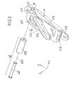
- FIG. 2 shows the distance ⁇ x between the center region 415 and by the two attachment points 411 and 412 on the B-pillar 81 of Motor vehicle body 8 formed mounting surface of the holding body 41st
- the belt insertion slot 413 and the Gurtaustrittsschlitz 414 recognize, each by punching in by a one-piece stamped and bent part made of sheet metal formed holding body are made.
- the Gurtaustrittsschlitz 414 has a reburied or rounded edge, which forms a deflection edge 416 of the belt exit slot 414.
- the stamped belt exit slot 414 can achieve that friction between the holding body 41 and the seat belt 1 is minimized. In addition, will Damage to the seat belt 1 avoided.
- FIG 2 can be seen beyond the upper deflecting element 42 through a steel pin 421 and a guide roller 422 is formed.
- the steel pin 421 will go along its deflection axis 423 held at two holding points 417 of the holding body 41.
- the Deflection roller 422 is rotatably mounted on the steel pin 421, so that the deflection roller 422 on the steel pin 421 very low-friction rotation.
- FIG. 2 also shows that the deflection edge 416 of the Gurtaustrittsschlitzes 414 and the deflection axis 423 of the upper deflecting 42nd form an angle ⁇ .
- the angle ⁇ can be in a range between 30 ° and 70 °, for example, in a range between 35 ° and 55 °. In which Embodiment according to the figure 2, the angle is about 45 °.
- Gurtein rawschlitz 413 and the deflection axis 423 are largely parallel aligned with each other.
- the holding body 41 is - as already explained - made in one piece; This means that the two attachment points 411 and 412, the two breakpoints 417, the Gurtein technologicalschlitz 413 and the Gurtaustrittschlitz 414 are integrally formed.
- the Holding body 41 may be, for example, by punching and bending a sheet, be formed, for example, a steel sheet.
- the holding body 41 also be formed by injection molding of plastic or die-cast aluminum. Around It is to enable a simple and inexpensive production of the holding body only advantageous if the holding body in one piece - as shown - is formed.
- the upper deflecting element 42 through the steel pin 421 and the guide roller 422 formed.
- the deflection bar or the deflection sheet metal part are then preferably formed integrally on the holding body 41.
Landscapes
- Engineering & Computer Science (AREA)
- Mechanical Engineering (AREA)
- Automotive Seat Belt Assembly (AREA)
Applications Claiming Priority (2)
| Application Number | Priority Date | Filing Date | Title |
|---|---|---|---|
| DE10346172A DE10346172A1 (de) | 2003-10-01 | 2003-10-01 | Gurtumlenkeinrichtung für einen Sicherheitsgurt eines Kraftfahrzeugs |
| DE10346172 | 2003-10-01 |
Publications (3)
| Publication Number | Publication Date |
|---|---|
| EP1520756A2 true EP1520756A2 (fr) | 2005-04-06 |
| EP1520756A3 EP1520756A3 (fr) | 2006-03-01 |
| EP1520756B1 EP1520756B1 (fr) | 2007-02-21 |
Family
ID=34306263
Family Applications (1)
| Application Number | Title | Priority Date | Filing Date |
|---|---|---|---|
| EP04090364A Expired - Lifetime EP1520756B1 (fr) | 2003-10-01 | 2004-09-20 | Renvoi de ceinture de sécurité pour véhicule automobile |
Country Status (5)
| Country | Link |
|---|---|
| US (1) | US7322611B2 (fr) |
| EP (1) | EP1520756B1 (fr) |
| JP (1) | JP4854189B2 (fr) |
| CN (1) | CN100381305C (fr) |
| DE (2) | DE10346172A1 (fr) |
Families Citing this family (4)
| Publication number | Priority date | Publication date | Assignee | Title |
|---|---|---|---|---|
| JP2007050824A (ja) * | 2005-08-19 | 2007-03-01 | Takata Corp | シートベルト用ガイドアンカーおよびこれを備えたシートベルト装置 |
| DE102008012951B4 (de) | 2008-03-06 | 2009-10-29 | Takata-Petri Ag | Gurtumlenkvorrichtung |
| US20160311396A1 (en) * | 2015-04-24 | 2016-10-27 | GM Global Technology Operations LLC | Belt buckle anchor for thin seats |
| DE102015213487A1 (de) * | 2015-07-17 | 2017-01-19 | Bayerische Motoren Werke Aktiengesellschaft | Sicherheitsgurtvorrichtung für ein Kraftfahrzeug und Kraftfahrzeug mit einer solchen Sicherheitsgurtvorrichtung |
Citations (2)
| Publication number | Priority date | Publication date | Assignee | Title |
|---|---|---|---|---|
| US5139282A (en) | 1991-05-06 | 1992-08-18 | General Motors Corporation | Shoulder belt comfort spring |
| DE10103319A1 (de) | 2001-01-25 | 2002-08-01 | Takata Europa Vehicle Safety T | Sicherheitsgurtvorrichtung |
Family Cites Families (12)
| Publication number | Priority date | Publication date | Assignee | Title |
|---|---|---|---|---|
| DE2551329A1 (de) * | 1975-11-15 | 1977-05-18 | Daimler Benz Ag | Oberes, hoehenverschiebbar in einem karosseriehohlraum angeordnetes beschlagteil eines schultergurtes |
| GB1577951A (en) * | 1976-04-26 | 1980-10-29 | Coenen Benelux Bv | Safety belt |
| EP0018122B1 (fr) * | 1979-04-03 | 1985-11-13 | Secretary of State for Transport in Her Britannic Majesty's Gov. of the United Kingdom of Great Britain and Northern Ireland | Dispositif de blocage pour une sangle |
| JPS58101856A (ja) * | 1981-12-15 | 1983-06-17 | Nissan Motor Co Ltd | シ−トベルトスル− |
| JPS62453A (ja) * | 1985-06-27 | 1987-01-06 | Konishiroku Photo Ind Co Ltd | クロルフエニルヒドラジン系化合物を製造する方法 |
| JPH03184749A (ja) * | 1989-12-11 | 1991-08-12 | Fanuc Ltd | 回転体ならい制御装置 |
| US5599070A (en) * | 1995-12-12 | 1997-02-04 | Trw Vehicle Safety Systems Inc. | Seat and integral seat belt |
| US5722732A (en) * | 1996-08-26 | 1998-03-03 | General Motors Corporation | Shoulder belt retractor with headrest support |
| JPH11217057A (ja) * | 1998-02-02 | 1999-08-10 | Nippon Seiko Kk | シートベルト支持装置 |
| DE19915024B4 (de) | 1999-04-01 | 2013-04-25 | TAKATA Aktiengesellschaft | Sicherheitsgurtanordnung bei Fahrzeugen |
| US7004503B2 (en) * | 2001-05-01 | 2006-02-28 | Takata-Petri (Ulm) Gmbh | Safety belt arrangement in vehicles |
| JP2003154922A (ja) * | 2001-11-19 | 2003-05-27 | Tokai Rika Co Ltd | プリテンショナ装置及びシートベルト装置 |
-
2003
- 2003-10-01 DE DE10346172A patent/DE10346172A1/de not_active Withdrawn
-
2004
- 2004-09-20 DE DE502004002942T patent/DE502004002942D1/de not_active Expired - Lifetime
- 2004-09-20 EP EP04090364A patent/EP1520756B1/fr not_active Expired - Lifetime
- 2004-09-30 JP JP2004286791A patent/JP4854189B2/ja not_active Expired - Fee Related
- 2004-09-30 CN CNB2004100833562A patent/CN100381305C/zh not_active Expired - Fee Related
- 2004-10-01 US US10/954,950 patent/US7322611B2/en not_active Expired - Fee Related
Patent Citations (2)
| Publication number | Priority date | Publication date | Assignee | Title |
|---|---|---|---|---|
| US5139282A (en) | 1991-05-06 | 1992-08-18 | General Motors Corporation | Shoulder belt comfort spring |
| DE10103319A1 (de) | 2001-01-25 | 2002-08-01 | Takata Europa Vehicle Safety T | Sicherheitsgurtvorrichtung |
Also Published As
| Publication number | Publication date |
|---|---|
| JP4854189B2 (ja) | 2012-01-18 |
| CN1618668A (zh) | 2005-05-25 |
| DE502004002942D1 (de) | 2007-04-05 |
| US20050104358A1 (en) | 2005-05-19 |
| JP2005104463A (ja) | 2005-04-21 |
| CN100381305C (zh) | 2008-04-16 |
| DE10346172A1 (de) | 2005-04-21 |
| EP1520756A3 (fr) | 2006-03-01 |
| EP1520756B1 (fr) | 2007-02-21 |
| US7322611B2 (en) | 2008-01-29 |
Similar Documents
| Publication | Publication Date | Title |
|---|---|---|
| EP2117885B1 (fr) | Ensemble ceinture de sécurité pour un véhicule automobile | |
| EP0376320B1 (fr) | Ferrure de renvoi, réglable en hauteur, pour ceintures de sécurité de véhicule | |
| EP2180807B1 (fr) | Dispositif de renvoi de ceinture de securite | |
| EP1983857A1 (fr) | Languette pour ceinture de securite | |
| DE102006043780A1 (de) | Führungsschlaufeneinheit | |
| DE10064770C2 (de) | Vorrichtung zur Lagerung eines Pedalhebels eines Kraftfahrzeuges | |
| DE69521760T2 (de) | Fahrzeugsitz | |
| DE102007046961A1 (de) | Energieabsorptions-Sitzverankerungs-Rückhaltesystem für Kinder-Sicherheitssitze | |
| DE102012001780A1 (de) | Sicherheitsgurt-Schlosszungenanordnung | |
| DE202007017349U1 (de) | Einrast-Führungsschlaufenanordnung | |
| DE102012219090A1 (de) | Sicherheitsgurt-Verschlussplattenanordnung | |
| DE102010049112A1 (de) | Beschlagteil zur Befestigung eines Spannbandes eines Vorhanggassackes an einem Fahrzeugteil | |
| DE102008022813A1 (de) | Kindersitz | |
| EP1358094A1 (fr) | Dispositif de fixation d'un levier de pedale d'un vehicule automobile | |
| DE3873468T2 (de) | Sicherheitsgurthaltevorrichtung mit manueller lageverstellung. | |
| DE102012221505B4 (de) | Sicherheitsgurtbefestigungsanordnung und Beschlagteil zur Befestigung eines Sicherheitsgurtes an einem Kraftfahrzeug | |
| EP1520756B1 (fr) | Renvoi de ceinture de sécurité pour véhicule automobile | |
| DE102007007702A1 (de) | Sicherheitsgurtanordnung für ein Kraftfahrzeug | |
| DE102014013080B4 (de) | Führungsschiene für einen Höhenversteller | |
| DE102006043450A1 (de) | Fahrzeuginsassen-Rückhaltebauteil | |
| EP1559619A1 (fr) | Dispositif de réglage en hauteur du renvoi d'une ceinture de sécurité | |
| DE3829929A1 (de) | Hoehenverstellvorrichtung fuer einen beschlag eines sicherheitsgurt-rueckhaltesystems in kraftfahrzeugen | |
| DE10051014C1 (de) | Befestigungsanordnung eines Sicherheitsgurtsystems mit Schnellmontageeinrichtung | |
| DE102021102087B4 (de) | Dämpfungssystem eines Fahrzeugsitzes | |
| WO1998000318A1 (fr) | Dispositif de reglage en hauteur pour ceinture de securite |
Legal Events
| Date | Code | Title | Description |
|---|---|---|---|
| PUAI | Public reference made under article 153(3) epc to a published international application that has entered the european phase |
Free format text: ORIGINAL CODE: 0009012 |
|
| AK | Designated contracting states |
Kind code of ref document: A2 Designated state(s): AT BE BG CH CY CZ DE DK EE ES FI FR GB GR HU IE IT LI LU MC NL PL PT RO SE SI SK TR |
|
| AX | Request for extension of the european patent |
Extension state: AL HR LT LV MK |
|
| PUAL | Search report despatched |
Free format text: ORIGINAL CODE: 0009013 |
|
| AK | Designated contracting states |
Kind code of ref document: A3 Designated state(s): AT BE BG CH CY CZ DE DK EE ES FI FR GB GR HU IE IT LI LU MC NL PL PT RO SE SI SK TR |
|
| AX | Request for extension of the european patent |
Extension state: AL HR LT LV MK |
|
| 17P | Request for examination filed |
Effective date: 20060509 |
|
| GRAP | Despatch of communication of intention to grant a patent |
Free format text: ORIGINAL CODE: EPIDOSNIGR1 |
|
| AKX | Designation fees paid |
Designated state(s): DE FR GB SE |
|
| RAP1 | Party data changed (applicant data changed or rights of an application transferred) |
Owner name: TAKATA - PETRI AG |
|
| GRAS | Grant fee paid |
Free format text: ORIGINAL CODE: EPIDOSNIGR3 |
|
| GRAA | (expected) grant |
Free format text: ORIGINAL CODE: 0009210 |
|
| AK | Designated contracting states |
Kind code of ref document: B1 Designated state(s): DE FR GB SE |
|
| REG | Reference to a national code |
Ref country code: GB Ref legal event code: FG4D Free format text: NOT ENGLISH |
|
| REF | Corresponds to: |
Ref document number: 502004002942 Country of ref document: DE Date of ref document: 20070405 Kind code of ref document: P |
|
| REG | Reference to a national code |
Ref country code: SE Ref legal event code: TRGR |
|
| GBT | Gb: translation of ep patent filed (gb section 77(6)(a)/1977) |
Effective date: 20070418 |
|
| ET | Fr: translation filed | ||
| PLBE | No opposition filed within time limit |
Free format text: ORIGINAL CODE: 0009261 |
|
| STAA | Information on the status of an ep patent application or granted ep patent |
Free format text: STATUS: NO OPPOSITION FILED WITHIN TIME LIMIT |
|
| 26N | No opposition filed |
Effective date: 20071122 |
|
| PGFP | Annual fee paid to national office [announced via postgrant information from national office to epo] |
Ref country code: GB Payment date: 20090916 Year of fee payment: 6 Ref country code: SE Payment date: 20090910 Year of fee payment: 6 |
|
| REG | Reference to a national code |
Ref country code: SE Ref legal event code: EUG |
|
| GBPC | Gb: european patent ceased through non-payment of renewal fee |
Effective date: 20100920 |
|
| PG25 | Lapsed in a contracting state [announced via postgrant information from national office to epo] |
Ref country code: GB Free format text: LAPSE BECAUSE OF NON-PAYMENT OF DUE FEES Effective date: 20100920 |
|
| REG | Reference to a national code |
Ref country code: DE Ref legal event code: R082 Ref document number: 502004002942 Country of ref document: DE Representative=s name: MAIKOWSKI & NINNEMANN PATENTANWAELTE, DE |
|
| PG25 | Lapsed in a contracting state [announced via postgrant information from national office to epo] |
Ref country code: SE Free format text: LAPSE BECAUSE OF NON-PAYMENT OF DUE FEES Effective date: 20100921 |
|
| REG | Reference to a national code |
Ref country code: DE Ref legal event code: R082 Ref document number: 502004002942 Country of ref document: DE Representative=s name: MAIKOWSKI & NINNEMANN PATENTANWAELTE, DE Effective date: 20120904 Ref country code: DE Ref legal event code: R081 Ref document number: 502004002942 Country of ref document: DE Owner name: TAKATA AKTIENGESELLSCHAFT, DE Free format text: FORMER OWNER: TAKATA-PETRI AG, 63743 ASCHAFFENBURG, DE Effective date: 20120904 Ref country code: DE Ref legal event code: R082 Ref document number: 502004002942 Country of ref document: DE Representative=s name: MAIKOWSKI & NINNEMANN PATENTANWAELTE PARTNERSC, DE Effective date: 20120904 Ref country code: DE Ref legal event code: R081 Ref document number: 502004002942 Country of ref document: DE Owner name: JOYSON SAFETY SYSTEMS GERMANY GMBH, DE Free format text: FORMER OWNER: TAKATA-PETRI AG, 63743 ASCHAFFENBURG, DE Effective date: 20120904 |
|
| REG | Reference to a national code |
Ref country code: FR Ref legal event code: PLFP Year of fee payment: 12 |
|
| REG | Reference to a national code |
Ref country code: FR Ref legal event code: PLFP Year of fee payment: 13 |
|
| REG | Reference to a national code |
Ref country code: FR Ref legal event code: PLFP Year of fee payment: 14 |
|
| PGFP | Annual fee paid to national office [announced via postgrant information from national office to epo] |
Ref country code: FR Payment date: 20171002 Year of fee payment: 14 |
|
| REG | Reference to a national code |
Ref country code: DE Ref legal event code: R082 Ref document number: 502004002942 Country of ref document: DE Representative=s name: MAIKOWSKI & NINNEMANN PATENTANWAELTE PARTNERSC, DE Ref country code: DE Ref legal event code: R081 Ref document number: 502004002942 Country of ref document: DE Owner name: JOYSON SAFETY SYSTEMS GERMANY GMBH, DE Free format text: FORMER OWNER: TAKATA AKTIENGESELLSCHAFT, 63743 ASCHAFFENBURG, DE |
|
| PG25 | Lapsed in a contracting state [announced via postgrant information from national office to epo] |
Ref country code: FR Free format text: LAPSE BECAUSE OF NON-PAYMENT OF DUE FEES Effective date: 20180930 |
|
| PGFP | Annual fee paid to national office [announced via postgrant information from national office to epo] |
Ref country code: DE Payment date: 20201127 Year of fee payment: 17 |
|
| REG | Reference to a national code |
Ref country code: DE Ref legal event code: R119 Ref document number: 502004002942 Country of ref document: DE |
|
| PG25 | Lapsed in a contracting state [announced via postgrant information from national office to epo] |
Ref country code: DE Free format text: LAPSE BECAUSE OF NON-PAYMENT OF DUE FEES Effective date: 20220401 |