EP1520629B1 - Duscheinrichtung - Google Patents
Duscheinrichtung Download PDFInfo
- Publication number
- EP1520629B1 EP1520629B1 EP04022259A EP04022259A EP1520629B1 EP 1520629 B1 EP1520629 B1 EP 1520629B1 EP 04022259 A EP04022259 A EP 04022259A EP 04022259 A EP04022259 A EP 04022259A EP 1520629 B1 EP1520629 B1 EP 1520629B1
- Authority
- EP
- European Patent Office
- Prior art keywords
- control valve
- control
- shower device
- valve
- shower
- Prior art date
- Legal status (The legal status is an assumption and is not a legal conclusion. Google has not performed a legal analysis and makes no representation as to the accuracy of the status listed.)
- Expired - Lifetime
Links
- 238000009434 installation Methods 0.000 title description 3
- 230000005540 biological transmission Effects 0.000 claims 1
- 230000001105 regulatory effect Effects 0.000 abstract 1
- XLYOFNOQVPJJNP-UHFFFAOYSA-N water Substances O XLYOFNOQVPJJNP-UHFFFAOYSA-N 0.000 description 12
- 241000894006 Bacteria Species 0.000 description 3
- 241000700605 Viruses Species 0.000 description 3
- 238000011161 development Methods 0.000 description 3
- 230000018109 developmental process Effects 0.000 description 3
- 230000036541 health Effects 0.000 description 2
- 239000000463 material Substances 0.000 description 2
- 229910000838 Al alloy Inorganic materials 0.000 description 1
- 230000004913 activation Effects 0.000 description 1
- 238000004026 adhesive bonding Methods 0.000 description 1
- 229910052782 aluminium Inorganic materials 0.000 description 1
- XAGFODPZIPBFFR-UHFFFAOYSA-N aluminium Chemical compound [Al] XAGFODPZIPBFFR-UHFFFAOYSA-N 0.000 description 1
- 244000052616 bacterial pathogen Species 0.000 description 1
- 230000004888 barrier function Effects 0.000 description 1
- 230000008901 benefit Effects 0.000 description 1
- 230000015572 biosynthetic process Effects 0.000 description 1
- 238000010276 construction Methods 0.000 description 1
- 230000006735 deficit Effects 0.000 description 1
- 230000001419 dependent effect Effects 0.000 description 1
- 238000010586 diagram Methods 0.000 description 1
- 239000003000 extruded plastic Substances 0.000 description 1
- 239000000446 fuel Substances 0.000 description 1
- 239000010720 hydraulic oil Substances 0.000 description 1
- 239000007788 liquid Substances 0.000 description 1
- 229910052751 metal Inorganic materials 0.000 description 1
- 239000002184 metal Substances 0.000 description 1
- 230000004048 modification Effects 0.000 description 1
- 238000012986 modification Methods 0.000 description 1
- 210000003205 muscle Anatomy 0.000 description 1
- 230000003287 optical effect Effects 0.000 description 1
- 239000011505 plaster Substances 0.000 description 1
- 239000004033 plastic Substances 0.000 description 1
- 230000002035 prolonged effect Effects 0.000 description 1
- 238000002604 ultrasonography Methods 0.000 description 1
- 238000003466 welding Methods 0.000 description 1
Images


Classifications
-
- E—FIXED CONSTRUCTIONS
- E03—WATER SUPPLY; SEWERAGE
- E03C—DOMESTIC PLUMBING INSTALLATIONS FOR FRESH WATER OR WASTE WATER; SINKS
- E03C1/00—Domestic plumbing installations for fresh water or waste water; Sinks
- E03C1/02—Plumbing installations for fresh water
- E03C1/04—Water-basin installations specially adapted to wash-basins or baths
- E03C1/0408—Water installations especially for showers
-
- E—FIXED CONSTRUCTIONS
- E03—WATER SUPPLY; SEWERAGE
- E03C—DOMESTIC PLUMBING INSTALLATIONS FOR FRESH WATER OR WASTE WATER; SINKS
- E03C1/00—Domestic plumbing installations for fresh water or waste water; Sinks
- E03C1/02—Plumbing installations for fresh water
- E03C1/05—Arrangements of devices on wash-basins, baths, sinks, or the like for remote control of taps
- E03C1/055—Electrical control devices, e.g. with push buttons, control panels or the like
-
- G—PHYSICS
- G05—CONTROLLING; REGULATING
- G05D—SYSTEMS FOR CONTROLLING OR REGULATING NON-ELECTRIC VARIABLES
- G05D23/00—Control of temperature
- G05D23/01—Control of temperature without auxiliary power
- G05D23/13—Control of temperature without auxiliary power by varying the mixing ratio of two fluids having different temperatures
- G05D23/1393—Control of temperature without auxiliary power by varying the mixing ratio of two fluids having different temperatures characterised by the use of electric means
Definitions
- the invention relates to a shower device with a shower head, a leading to this feed line and connected to the latter from the shower head spaced control valve.
- Such shower facilities are found in a variety of forms such as shown in WO0154822.
- the feed line is usually laid under plaster and the control valve is located in showers typically at chest level.
- Similar shower facilities are also known in bathtubs, wherein the control valve has a further outlet with which the bathtub can be filled directly, and wherein the feed line is a flexible hose.
- control valves mixers are usually used to adjust the amount and temperature of the shower head supplied water. Frequently also thermostatically controlled mixers are used.
- a shower device according to the preamble of claim 1 is to be developed so that the risk of such health impairments is eliminated.
- the feed line is constantly free of air and in the immediate vicinity of the shower head with clean water. So it can not settle here bacteria and viruses. Nevertheless, the operation of the shower is ensured from an easily accessible place.
- the adjustment of the amount of water and possibly the setting of the water temperature and the opening and closing of the control valve can be made substantially from the same place. This facilitates the handling of the user.
- the remote control valve can also be operated without an electrical power source.
- the energy for adjusting the control valve is controlled from the pressure energy of Taken from water or provided by muscle power.
- the embodiment of the invention according to claim 8 is characterized by mechanically particularly simple construction.
- 10 denotes a shower head as a whole, which is connected via a feed line 12 to a mixing fitting 14, which is shown as a single-lever mixer.
- the mixing valve 14 is the input side connected to a cold water pipe 16 and a hot water pipe 18.
- the shower head 10 comprises, in addition to the actual shower part 20, a control valve 22 which is inserted into the channel leading to the shower part 20 of the shower head housing 10.
- the control valve 22 is shown as a solenoid valve. Its solenoid 24 is connected via a line 26 to the output of an amplifier 28, which is driven by the output of a single-digit binary counter 30 ago. The input of the binary counter 30 is connected to the output of a button 32 having a large actuator plate 34.
- An input of the button 32 is connected to the output of a voltage source 36.
- a voltage source 36 This can be a battery, a photoelectric device, a fuel cell or even operated with mains voltage wet room-suitable power supply. This also serves to power the binary counter 30 and the amplifier 28 and any other electrical components of the shower device, which are not shown in the drawing, such as displays on the operating state, etc.
- the mixing valve 14 is deviating from conventional mixing valves designed so that a throttled connection between the cold water pipe and the feed line 12 also in the "closed position" of the mixing valve 14 remains. In this way, the inlet of the control valve 22 is always acted upon by pressurized water.
- the user adjusts the desired throughput and the desired temperature at the mixing fitting 14. Then it actuates the actuator plate 34 of the button 32, whereby the output of the single-digit binary counter changes. Accordingly, an activation signal for the actuating magnet 24 is obtained at the output of the amplifier 28, so that the control valve 22 opens. Now, water is dispensed from the shower part 20 at the desired temperature and in the amount set on the mixing fitting 14.
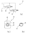
- FIG. 2 shows a modified control valve 22, which has a pilot control valve 38 and a main control valve 34.
- the pilot valve 38 is resiliently biased in the closed position and can be brought by energizing the solenoid 24 in the open position.
- the main valve 40 is resiliently biased in the closed position and includes a control cylinder 42 which is connected to the working opening of the pilot valve 38 and when pressurized, the main control valve 40 moves against the spring bias in the open position.
- control line 26 and the feed line 12 are shown closely adjacent. In practice, you will connect these two lines to a one-piece unit, z. By gluing, welding or mechanically (eg, pushing in a flexible control cable into a groove provided in the outer surface of the feed line 12).
- FIG. 3 shows an axial view of the connection end of a practical embodiment of a control valve 22.
- connection piece 44 made of metal is injected into a valve housing 46.
- the connection piece 44 has a standard thread which can be screwed into a standard thread of the feed line 12.
- a connecting piece 44 adjacent nozzle 48 of the housing carries an electrical contact 50 which is resilient in itself or biased by a spring in the axial outward direction.
- the contact 50 is connected via a fixed contact, which in the drawing is not reproduced, the connection to the line 26 ago.
- valve housing 46 Inside the valve housing 46, the valve assembly shown in Figure 2 is housed.
- control valve 22 has an outlet-side connecting piece 44 which is provided with a standard thread, which allows the screwing of standard shower heads.
- control valve 22 shown in Figure 3 thus any standard shower heads can be used, which in turn is ensured that no viruses or bacteria can settle in the feed line.
- the control valve 22 shown in Figure 3 can also be used in conjunction with hand showers.
- the control line 26 designed as a flexible cable is then arranged inside a flexible feed hose 52.
- the conventional connection fittings carried by the supply hose 52 are made of plastic material and carry flanges with contacts which cooperate with the contact 50 of the control valve 22 and a spatially fixed contact, not shown in the drawing, which is provided at the shower connection of the mixing fitting 14.
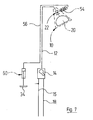
- FIG. 5 shows a modified embodiment with fluidic actuation of the control valve 22.
- Parts of the shower device, which have already been explained with reference to Figure 1 are again provided with the same reference numerals and will not be described again in detail below.
- the control valve 22 now has an actuating cylinder 54, which logically corresponds to the actuating cylinder 42 of Figure 2.
- the pilot valve 38 is now not a solenoid valve but a mechanically operated valve.
- the actuation takes place from the actuating plate 34, which is mechanically connected via a two-position gear 58 with the actuator of the pilot valve 38.
- the two-position gear 58 may be configured similarly as known from the adjustment of ballpoint pen refills ago. Each time its input element is actuated, the position of the output element is changed between two different end positions.
- a master cylinder 60 at the end of the control line 56 adjacent to the mixing fitting.
- the control line 56 and the working spaces of the actuating cylinder 54 and the master cylinder 60 are filled with a closed volume of an actuating liquid, which may be water or even a hydraulic oil.
- the actuation of the main valve 40 is effected by a displaceable actuating member 34, which is mechanically coupled to the piston of the master cylinder 60.
- FIG. 6 shows a transverse section through a two-channel tube, which may be made of extruded aluminum or an extruded aluminum alloy or an extruded plastic material.
- This two-channel tube 62 has a control channel 64, which forms the control line 56, and a water channel 66, which forms the feed line 12.
- a monostable solenoid valve may also be used. This is preferably used when the voltage source 36 is a power supply or is powered by such.
- a bistable solenoid valve is preferably used as the control valve 22.
- buttons 32 instead of the button 32 also any other sensor can be used, which can be caused by a user for the targeted delivery of an electrical signal.
- sensors include primarily IR light barriers, optical sensors, other present-day sensors such as radar sensors, ultrasound sensors, etc.
Landscapes
- Engineering & Computer Science (AREA)
- Hydrology & Water Resources (AREA)
- Water Supply & Treatment (AREA)
- Public Health (AREA)
- Health & Medical Sciences (AREA)
- Life Sciences & Earth Sciences (AREA)
- Automation & Control Theory (AREA)
- Physics & Mathematics (AREA)
- General Physics & Mathematics (AREA)
- Bathtubs, Showers, And Their Attachments (AREA)
- Domestic Plumbing Installations (AREA)
- Devices That Are Associated With Refrigeration Equipment (AREA)
- Vehicle Body Suspensions (AREA)
- Massaging Devices (AREA)
- Catching Or Destruction (AREA)
Description
- Die Erfindung betrifft eine Duscheinrichtung mit einem Duschkopf, einer zu diesem führenden Speiseleitung und einer mit der letzteren verbundenen vom Duschkopf beabstandeten Steuerarmatur.
- Derartige Duscheinrichtungen sind in vielfältiger Form anzutreffen wie beispielsweise in WO0154822 gezeigt. Die Speiseleitung ist in der Regel unter Putz verlegt und die Steuerarmatur befindet sich in Duschen typischerweise in Brusthöhe. Ähnliche Duscheinrichtungen sind aber auch an Badewannen bekannt, wobei die Steuerarmatur einen weiteren Auslaß aufweist, mit dem die Badewanne direkt befüllt werden kann, und wobei die Speiseleitung ein flexibler Schlauch ist.
- Als Steuerarmaturen werden in der Regel Mischer verwendet, die Menge und Temperatur des dem Duschkopf zugeführten Wassers einzustellen gestatten. Häufig werden auch thermostatgesteuerte Mischer verwendet.
- In derartigen Duscheinrichtungen kann es ähnlich wie in Klimaanlagen dazu kommen, daß sich bei längerem Nichtgebrauch in der Speiseleitung Viren oder Bakterien ansiedeln. Hierdurch wird die Gesundheit der Benutzer gefährdet.
- Durch die vorliegende Erfindung soll eine Duscheinrichtung gemäß dem Oberbegriff des Anspruchs 1 so weitergebildet werden, daß die Gefahr derartiger gesundheitlicher Beeinträchtigungen ausgeräumt ist.
- Diese Aufgabe ist erfindungsgemäß gelöst durch eine Duscheinrichtung mit den im Anspruch 1 angegebenen Merkmalen.
- Bei der erfindungsgemäßen Duscheinrichtung ist die Speiseleitung bis in unmittelbare Nähe des Duschkopfs ständig luftfrei und mit sauberem Wasser gefüllt. Es können sich hier also keine Bakterien und Viren ansiedeln. Trotzdem ist die Betätigung der Dusche von einem gut zugänglichen Ort aus gewährleistet.
- Vorteilhafte Weiterbildungen der Erfindung sind Gegenstand von Unteransprüchen.
- Bei einer Duscheinrichtung gemäß Anspruch 2 kann das Einstellen der Wassermenge und ggf. das Einstellen der Wassertemperatur und das Öffnen und Schließen des Steuerventils im wesentlichen vom gleichen Ort aus erfolgen. Dies erleichtert dem Benutzer die Handhabung.
- Verwendet man gemäß Anspruch 3 als Steuerventil ein Magnetventil, so kann man eine einfache und nur wenig Platz benötigende Steuerleitung verwenden. Diese Leitung kann auch über größere Strecken problemlos beim Einrichten eines Bads oder einer Dusch verlegt werden.
- Mit der Weiterbildung der Erfindung gemäß Anspruch 4 wird erreicht, daß das Magnetventil keinen großen Durchströmquerschnitt zu haben braucht. Derartige Magnetventile sind preisgünstig auf dem Markt erhältlich. Auch die Energieversorgung eines kleinen Magnetventils ist einfach und insbesondere auch aus Batterien oder anderen wenig leistungsfähigen Stromquellen möglich.
- Bei einer Duscheinrichtung gemäß Anspruch 5 kann das fernbediente Steuerventil auch ohne elektrische Stromquelle betätigt werden. Die Energie zum Verstellen des Steuerventils wird aus der Druckenergie des gesteuerten Wasserstroms entnommen bzw. durch Muskelkraft erbracht.
- Dabei ist die Weiterbildung der Erfindung gemäß Anspruch 6 im Hinblick auf einen einfachen Anschluß des Duschkopfs und ein einfaches Verlegen von Speiseleitung und Steuerleitung von Vorteil.
- Bei einer Duscheinrichtung gemäß Anspruch 7 braucht man nur eine einzige Leitung zum Duschkopf zu legen.
- Die Ausbildung der Erfindung gemäß Anspruch 8 zeichnet sich durch mechanisch besonders einfachen Aufbau aus.
- Nachstehend wird die Erfindung anhand von Ausführungsbeispielen unter Bezugnahme auf die Zeichnung näher erläutert. In dieser zeigen:
- Figur 1
- eine schematische Darstellung einer Duscheinrichtung;
- Figur 2
- ein Blockschaltbild einer abgewandelten Steuerventilanordnung, die anstelle eines in Figur 1 gezeigten Duschkopf-Steuerventils verwendbar ist;
- Figur 3
- eine axiale Aufsicht auf ein praktisches Ausführungsbeispiel einer Steuerventilanordnung gemäß Figur 2;
- Figur 4
- einen transversalen Schnitt durch einen flexiblen Schlauch mit integrierter Steuerleitung für ein Duschkopf-Steuerventil;
- Figur 5
- eine ähnliche Ansicht wie Figur 1, in welcher ein fluidbetätigtes Duschkopf-Steuerventil wiedergegeben ist;
- Figur 6
- einen transversalen Schnitt durch eine bevorzugte Ausführung einer doppelten Verbindungsleitung zum Duschkopf, welche einen Speisewasserkanal und einen Steuerdruckkanal aufweist; und
- Figur 7
- eine ähnliche Ansicht wie Figur 1, in welcher ein hydromechanisch betätigtes Duschkopf-Steuerventil dargestellt ist.
- In Figur 1 ist mit 10 insgesamt ein Duschkopf bezeichnet, der über eine Speiseleitung 12 mit einer Mischarmatur 14 verbunden ist, die als Einhebelmischer dargestellt ist. Die Mischarmatur 14 ist eingangsseitig mit einer Kaltwasserleitung 16 und einer Warmwasserleitung 18 verbunden.
- Der Duschkopf 10 umfaßt neben dem eigentlichen Brausenteil 20 ein Steuerventil 22, welches in den zum Brausenteil 20 führenden Kanal des Duschkopfgehäuses 10 eingefügt ist. Das Steuerventil 22 ist als Magnetventil dargestellt. Sein Stellmagnet 24 ist über eine Leitung 26 mit dem Ausgang eines Verstärkers 28 verbunden, der vom Ausgang eines einstelligen Binärzählers 30 her angesteuert wird. Der Eingang des Binärzählers 30 ist mit dem Ausgang eines Tasters 32 verbunden, der eine große Betätigungsplatte 34 aufweist.
- Ein Eingang des Tasters 32 ist mit dem Ausgang einer Spannungsquelle 36 verbunden. Hierbei kann es sich um eine Batterie, eine fotoelektrische Einrichtung, eine Brennstoffzelle oder auch ein mit Netzspannung betriebenes Feuchtraum-geeignetes Netzteil handeln. Dieses dient zugleich zur Energieversorgung des Binärzählers 30 und des Verstärkers 28 sowie etwaiger weiterer elektrischer Komponenten der Duscheinrichtung, die in der Zeichnung nicht wiedergegeben sind, wie Anzeigen über den Betriebszustand usw.
- Die Mischarmatur 14 ist abweichend von sonst üblichen Mischarmaturen so ausgebildet, daß eine gedrosselte Verbindung zwischen der Kaltwasserleitung und der Speiseleitung 12 auch in der "Schließstellung" der Mischarmatur 14 verbleibt. Auf diese Weise ist der Einlaß des Steuerventils 22 stets mit unter Druck stehendem Wasser beaufschlagt.
- Die Bedienung der Duscheinrichtung gemäß Figur 1 erfolgt so:
- Der Benutzer stellt an der Mischarmatur 14 den gewünschten Durchsatz und die gewünschte Temperatur ein. Dann betätigt er die Betätigungsplatte 34 des Tasters 32, wodurch sich das Ausgangssignal des einstelligen Binärzählers ändert. Entsprechend erhält man am Ausgang des Verstärkers 28 ein Aktivierungssignal für den Stellmagneten 24, so daß das Steuerventil 22 öffnet. Nun wird Wasser mit der gewünschten Temperatur und in der an der Mischarmatur 14 eingestellten Menge vom Brausenteil 20 abgegeben.
- Zum Beenden des Duschens wird einfach die Betätigungsplatte 34 nochmals gedrückt, wodurch das Ausgangssignal am Binärzähler 30 verschwindet und damit auch das Speisesignal für den Stellmagneten 24, welches am Ausgang des Verstärkers 28 bereitgestellt wird. In der Speiseleitung 12 bleibt aber ein Druck aufrechterhalten. Diese Leitung bleibt so voll mit Wasser gefüllt, so daß keine Möglichkeit der Bildung von Keimen besteht.
- Figur 2 zeigt ein abgewandeltes Steuerventil 22, welches ein Vorsteuerventil 38 und ein Hauptsteuerventil 34 aufweist.
- Das Vorsteuerventil 38 ist federnd in die Schließstellung vorgespannt und kann durch Erregung des Stellmagneten 24 in die Offenstellung gebracht werden. Das Hauptventil 40 ist federnd in die Schließstellung vorgespannt und umfaßt einen Stellzylinder 42, welcher mit der Arbeitsöffnung des Vorsteuerventils 38 verbunden ist und bei Druckbeaufschlagung das Hauptsteuerventil 40 entgegen der Federvorspannung in die Offenstellung bewegt.
- In Figur 2 sind die Steuerleitung 26 und die Speiseleitung 12 eng benachbart dargestellt. In der Praxis wird man diese beiden Leitungen zu einer einstückig handhabbaren Einheit verbinden, z. B. durch Verkleben, Verschweißen oder mechanisch (z. B. Eindrücken eines flexiblen Steuerkabels in eine Nut, die in der Außenfläche der Speiseleitung 12 vorgesehen ist).
- Figur 3 zeigt eine Axialaufsicht auf das Anschlußende eines praktischen Ausführungsbeispiels für ein Steuerventil 22.
- Ein einlaßseitiger Anschlußstutzen 44 aus Metall ist in ein Ventilgehäuse 46 eingespritzt. Der Anschlußstutzen 44 hat ein Standardgewinde, welches in ein Standardgewinde der Speiseleitung 12 einschraubbar ist.
- Ein dem Anschlußstutzen 44 benachbarter Stutzen 48 des Gehäuses trägt einen elektrischen Kontakt 50, der in sich federnd ausgebildet ist oder durch eine Feder in axialer Auswärtsrichtung vorgespannt ist. Der Kontakt 50 stellt über einen raumfesten Gegenkontakt, der in der Zeichnung nicht wiedergegeben ist, die Verbindung zur Leitung 26 her.
- Im Inneren des Ventilgehäuses 46 ist die in Figur 2 gezeigte Ventilanordnung untergebracht.
- An seiner zweiten, in Figur 3 hinter der Zeichenebene zu denkenden Stirnfläche hat das Steuerventil 22 einen auslaßseitigen Anschlußstutzen 44, der mit einem Standardgewinde versehen ist, welches das Aufschrauben von Standard-Duschköpfen gestattet.
- Mit dem in Figur 3 gezeigten Steuerventil 22 können somit beliebige Standard-Duschköpfe verwendet werden, wobei wiederum gesichert ist, daß sich in der Speiseleitung keine Viren oder Bakterien ansiedeln können.
- Das in Figur 3 gezeigte Steuerventil 22 läßt sich auch in Verbindung mit Handbrausen verwenden. In diesem Fall ist dann im Inneren eines flexiblen Speiseschlauchs 52 die als flexibles Kabel ausgebildete Steuerleitung 26 angeordnet. Die von dem Speiseschlauch 52 getragenen herkömmlichen Anschlußarmaturen sind aus Plastikmaterial hergestellt und tragen Flansche mit Kontakten, die mit dem Kontakt 50 des Steuerventils 22 bzw. einem raumfesten in der Zeichnung nicht dargestellten Kontakt zusammenarbeiten, der beim Brausenanschluß der Mischarmatur 14 vorgesehen ist.
- Figur 5 zeigt ein abgewandeltes Ausführungsbeispiel mit fluidischer Betätigung des Steuerventils 22. Teile der Duscheinrichtung, die unter Bezugnahme auf Figur 1 schon erläutert wurden, sind wieder mit den selben Bezugszeichen versehen und werden nachstehend nicht nochmals detailliert beschrieben.
- Das Steuerventil 22 hat nun einen Stellzylinder 54, der logisch dem Stellzylinder 42 von Figur 2 entspricht. Das in Figur 2 gezeigte Vorsteuerventil 38 ist aber nun vom Duschkopf entfernt angeordnet und über eine fluidische Steuerleitung 56 angeschlossen, die bis in die Nähe der Mischarmatur 14 geführt ist. Dort befindet sich das Vorsteuerventil 38 in unmittelbarer Nachbarschaft der Mischarmatur 14. Das Vorsteuerventil 38 ist nun kein Magnetventil sondern ein mechanisch betätigtes Ventil. Die Betätigung erfolgt von der Betätigungsplatte 34 her, die über ein Zweistellungsgetriebe 58 mechanisch mit dem Stellglied des Vorsteuerventils 38 verbunden ist. Das Zweistellungsgetriebe 58 kann ähnlich ausgebildet sein, wie von der Verstellung von Kugelschreiberminen her bekannt. Bei jeder Betätigung seines Eingangsgliedes wird die Lage des Ausgangsgliedes zwischen zwei unterschiedlichen Endlagen verändert.
- Das Ausführungsbeispiel nach Figur 5 arbeitet genauso wie dasjenige nach Figur 1. Man benötigt aber keinerlei elektrische Einrichtungen.
- In weiterer Abwandlung des Ausführungsbeispiels nach Figur 5 kann man gemäß Figur 7 bei dem der Mischarmatur benachbarten Ende der Steuerleitung 56 einen Geberzylinder 60 vorsehen. Die Steuerleitung 56 und die Arbeitsräume des Betätigungszylinders 54 und des Geberzylinders 60 sind mit einem geschlossenen Volumen einer Betätigungsflüssigkeit gefüllt, die Wasser oder auch ein Hydrauliköl sein kann. Die Betätigung des Hauptventils 40 erfolgt durch ein verschiebbares Betätigungsglied 34, welches mechanisch mit dem Kolben des Geberzylinders 60 gekoppelt ist.
- Figur 6 zeigt einen transversalen Schnitt durch ein zweikanaliges Rohr, welches aus extrudiertem Aluminium oder einer extrudierten Aluminiumlegierung oder einem extrudierten Kunststoffmaterial hergestellt sein kann. Dieses zweikanalige Rohr 62 hat einen Steuerkanal 64, welcher die Steuerleitung 56 bildet, sowie einen Wasserkanal 66, der die Speiseleitung 12 bildet.
- Auf diese Weise kann man die gesamte Installation zwischen Betätigungsort und Befestigungsort des Duschkopfes 10 in einem einzigen Schlitz einer Mauer unterbringen.
- Anstelle des in Figur 1 gezeigten Steuerventiles 22 kann auch ein monostabiles Magnetventil verwendet werden. Dieses wird bevorzugt dann eingesetzt, wenn die Spannungsquelle 36 ein Netzteil ist oder aus einem solchen gespeist wird.
- Ist die Spannungsquelle 36 dagegen eine Batterie oder ein Akkumulator, wird als Steuerventil 22 vorzugsweise ein bistabiles Magnetventil verwendet.
- Obenstehend wurde die elektrische Betätigung des Steuerventiles 22 unter Bezugnahme auf den Taster 32 beschrieben.
- Es versteht sich, daß anstelle des Tasters 32 auch beliebige andere Fühler verwendet werden können, die von einem Benutzer zur gezielten Abgabe eines elektrischen Signales veranlasst werden können. Hierzu gehören in erster Linie IR-Lichtschranken, optische Sensoren, andere Gegenwartsfühler wie Radar-Sensoren, Ultraschalls-Sensoren usw..
Claims (8)
- Duscheinrichtung mit einem Duschkopf (10), einer zu diesem führenden Speiseleitung (12) und einer mit dieser verbundenen vom Duschkopf (10) beabstandeten Steuerarmatur (14), dadurch gekennzeichnet, daß die Speiseleitung (12) in der Nachbarschaft von deren duschkopfseitigen Ende ein fernbedientes Steuerventil (22) aufweist.
- Duscheinrichtung nach Anspruch 1, dadurch gekennzeichnet, daß ein Betätigungsteil (34) für das Steuerventil (22) in der Nachbarschaft der Steuerarmatur (14) angeordnet oder in diese integriert ist.
- Duscheinrichtung nach Anspruch 1 oder 2, dadurch gekennzeichnet, daß das Steuerventil (22) einen Stellmagneten (24) umfaßt.
- Duscheinrichtung nach Anspruch 3, dadurch gekennzeichnet, daß der Stellmagnet (24) ein Vorsteuerventil (38) betätigt, dessen Arbeitsöffnung mit einem Stellzylinder (42) eines Hauptsteuerventils (40) verbunden ist.
- Duscheinrichtung nach Anspruch 1 oder 2, dadurch gekennzeichnet, daß das Steuerventil (22) einen Betätigungszylinder (54) aufweist, der über eine Steuerleitung (56) mit einem Vorsteuerventil (38) oder einem Geberzylinder (60) verbunden ist, welche durch das Betätigungsteil (34) betätigbar sind.
- Duscheinrichtung nach Anspruch 5, dadurch gekennzeichnet, daß die Steuerleitung (56) und die Speiseleitung (12) zu einer Einheit zusammengefaßt sind.
- Duscheinrichtung nach Anspruch 6, dadurch gekennzeichnet, daß die Steuerleitung (56) und die Speiseleitung (12) zumindest teilweise durch ein Rohr (62) gebildet sind, welches zwei Kanäle (64, 68) aufweist.
- Duscheinrichtung nach Anspruch 1 oder 2, dadurch gekennzeichnet, daß ein Stellteil des Steuerventiles (22) über eine mechanische oder fluidische Kraftübertragunsstrecke (54, 56, 60) mit einem der Mischarmatur (14) benachbarten Betätigungsglied (34) verbunden ist.
Applications Claiming Priority (2)
| Application Number | Priority Date | Filing Date | Title |
|---|---|---|---|
| DE20315306U | 2003-10-01 | ||
| DE20315306U DE20315306U1 (de) | 2003-10-01 | 2003-10-01 | Duscheinrichtung |
Publications (3)
| Publication Number | Publication Date |
|---|---|
| EP1520629A2 EP1520629A2 (de) | 2005-04-06 |
| EP1520629A3 EP1520629A3 (de) | 2005-04-27 |
| EP1520629B1 true EP1520629B1 (de) | 2006-06-14 |
Family
ID=34306458
Family Applications (1)
| Application Number | Title | Priority Date | Filing Date |
|---|---|---|---|
| EP04022259A Expired - Lifetime EP1520629B1 (de) | 2003-10-01 | 2004-09-18 | Duscheinrichtung |
Country Status (4)
| Country | Link |
|---|---|
| US (1) | US20050082396A1 (de) |
| EP (1) | EP1520629B1 (de) |
| AT (1) | ATE329695T1 (de) |
| DE (2) | DE20315306U1 (de) |
Families Citing this family (3)
| Publication number | Priority date | Publication date | Assignee | Title |
|---|---|---|---|---|
| TR201617045A2 (tr) * | 2016-11-23 | 2017-05-22 | Goekmen Senerler | Sıcaklık ayarı yapabilen duş başlığı. |
| DE202021103647U1 (de) * | 2021-07-07 | 2022-10-18 | Neoperl GmbH | Sanitäre Anordnung |
| US12565764B2 (en) | 2023-05-31 | 2026-03-03 | Fortune Brands Water Innovations | Retrofit electronic plumbing system |
Family Cites Families (20)
| Publication number | Priority date | Publication date | Assignee | Title |
|---|---|---|---|---|
| US4426745A (en) * | 1981-06-13 | 1984-01-24 | Walker Crosweller & Company Ltd. | Ablutionary shower systems |
| AU599845B2 (en) * | 1987-10-26 | 1990-07-26 | Graeme Charles Dodds | An irrigation system |
| US5121511A (en) * | 1989-11-27 | 1992-06-16 | Matsushita Electric Works, Ltd. | Shower device |
| US5152465A (en) * | 1991-06-10 | 1992-10-06 | Calabro Daniel J | Shower flow controller |
| US5333785A (en) * | 1991-12-19 | 1994-08-02 | Dodds Graeme C | Wireless irrigation system |
| US5220914A (en) * | 1992-10-26 | 1993-06-22 | Thompson Thomas W | Plaque dislodging apparatus |
| US5445181A (en) * | 1994-09-15 | 1995-08-29 | Kohler Co. | Mixing valve |
| DE19501014A1 (de) * | 1995-01-14 | 1996-07-18 | Grohe Armaturen Friedrich | Automatische Duschensteuerung |
| US5839658A (en) * | 1996-09-27 | 1998-11-24 | Sarver; Larry C. | Method of retrofitting irrigation control systems |
| US5813655A (en) * | 1996-10-11 | 1998-09-29 | Pinchott; Gordon A. | Remote-control on/off valve |
| US5918811A (en) * | 1997-06-12 | 1999-07-06 | Speakman Company | Showerhead with variable spray patterns and internal shutoff valve |
| AUPP333598A0 (en) * | 1998-05-05 | 1998-05-28 | Watergate Enviroshower Pty. Ltd. | Control apparatus for showers |
| US6149071A (en) * | 1998-06-10 | 2000-11-21 | Global Metering Solutions, Llc | Flow control system for spray applications |
| JP2000139549A (ja) * | 1998-11-10 | 2000-05-23 | Ohiro Seisakusho:Kk | 自動洗髪機 |
| US6401742B1 (en) * | 1999-11-08 | 2002-06-11 | Dean L. Cramer | Moisture sensor and irrigation control system |
| EP1313567A2 (de) * | 2000-01-28 | 2003-05-28 | Pierre Tournier | Hygienischer brausekopf mit lösbarem diffusor |
| US6438770B1 (en) * | 2000-07-25 | 2002-08-27 | Invent Resources, Inc. | Electronically-controlled shower system |
| US6565018B1 (en) * | 2001-02-09 | 2003-05-20 | Degeyter John D | Shower flow control device |
| US6550697B2 (en) * | 2001-08-28 | 2003-04-22 | Globe Union Industrial Corp. | Shower head assembly |
| US6807983B1 (en) * | 2003-05-06 | 2004-10-26 | Kohler Co. | Valve assembly with swivel escutcheon |
-
2003
- 2003-10-01 DE DE20315306U patent/DE20315306U1/de not_active Expired - Lifetime
-
2004
- 2004-09-18 EP EP04022259A patent/EP1520629B1/de not_active Expired - Lifetime
- 2004-09-18 DE DE502004000757T patent/DE502004000757D1/de not_active Expired - Fee Related
- 2004-09-18 AT AT04022259T patent/ATE329695T1/de not_active IP Right Cessation
- 2004-09-27 US US10/951,010 patent/US20050082396A1/en not_active Abandoned
Also Published As
| Publication number | Publication date |
|---|---|
| EP1520629A3 (de) | 2005-04-27 |
| DE502004000757D1 (de) | 2006-07-27 |
| US20050082396A1 (en) | 2005-04-21 |
| EP1520629A2 (de) | 2005-04-06 |
| DE20315306U1 (de) | 2005-03-17 |
| ATE329695T1 (de) | 2006-07-15 |
Similar Documents
| Publication | Publication Date | Title |
|---|---|---|
| EP2218840B1 (de) | Sanitärarmatur mit Joysticksteuerung | |
| EP0313913A2 (de) | Mischvorrichtung | |
| DE19834151C1 (de) | Ventil für Warmwasseranlagen | |
| EP0904469B1 (de) | Als einhebelmischer ausgebildete sanitärarmatur | |
| DE102013001584A1 (de) | Sanitäranordnung | |
| DE202016103273U1 (de) | Ein Schaltmechanismus zum Steuern der Wasserströmungsrichtung mit gepulstem elektromagnetischem Ventil und ein Duschkopf | |
| WO2006094587A1 (de) | Brauseeinrichtung | |
| EP2653622A1 (de) | Einsatz zum wahlweisen Bereitstellung von zwei unterschiedlichen Durchflussmengen | |
| DE4431127C2 (de) | Sanitärventil mit einem Magnetventil | |
| EP1018063B1 (de) | Regler | |
| WO1994018509A1 (de) | Adapterarmatur zum wahlweisen anschluss eines heizkörpers | |
| EP1520629A2 (de) | Duscheinrichtung | |
| EP2889522B1 (de) | Wasserschalteinheit | |
| EP0572501B1 (de) | Heizungsventil | |
| DE4108458A1 (de) | Sanitaerarmatur | |
| CH621378A5 (en) | Upwardly directed shower device for WCs | |
| DE19813296A1 (de) | Mischbatterie | |
| DE102005042701A1 (de) | Anordnung zum Ein- oder Ausschalten des Wasserflusses einer Bewässerungsanlage | |
| EP2543780A1 (de) | Brausenmodul und Duschsystem mit elektronischer Steuerung | |
| DE2012827C3 (de) | Ventilaufsatz | |
| EP1656518A1 (de) | Modulares ventil- und verteilersystem | |
| EP0610703A2 (de) | Regler | |
| DE2912583A1 (de) | Sanitaere mischbatterie | |
| EP2660397A1 (de) | Anlage zur Versorgung eines Löschwasserverbrauchers | |
| DE102007011178A1 (de) | Elektrische Steuereinrichtung für eine Sanitärarmatur sowie Santiärarmatur mit einer solchen Steuereinrichtung |
Legal Events
| Date | Code | Title | Description |
|---|---|---|---|
| PUAI | Public reference made under article 153(3) epc to a published international application that has entered the european phase |
Free format text: ORIGINAL CODE: 0009012 |
|
| PUAL | Search report despatched |
Free format text: ORIGINAL CODE: 0009013 |
|
| AK | Designated contracting states |
Kind code of ref document: A2 Designated state(s): AT BE BG CH CY CZ DE DK EE ES FI FR GB GR HU IE IT LI LU MC NL PL PT RO SE SI SK TR |
|
| AX | Request for extension of the european patent |
Extension state: AL HR LT LV MK |
|
| AK | Designated contracting states |
Kind code of ref document: A3 Designated state(s): AT BE BG CH CY CZ DE DK EE ES FI FR GB GR HU IE IT LI LU MC NL PL PT RO SE SI SK TR |
|
| AX | Request for extension of the european patent |
Extension state: AL HR LT LV MK |
|
| 17P | Request for examination filed |
Effective date: 20051027 |
|
| GRAP | Despatch of communication of intention to grant a patent |
Free format text: ORIGINAL CODE: EPIDOSNIGR1 |
|
| AKX | Designation fees paid |
Designated state(s): AT BE BG CH CY CZ DE DK EE ES FI FR GB GR HU IE IT LI LU MC NL PL PT RO SE SI SK TR |
|
| GRAS | Grant fee paid |
Free format text: ORIGINAL CODE: EPIDOSNIGR3 |
|
| GRAA | (expected) grant |
Free format text: ORIGINAL CODE: 0009210 |
|
| AK | Designated contracting states |
Kind code of ref document: B1 Designated state(s): AT BE BG CH CY CZ DE DK EE ES FI FR GB GR HU IE IT LI LU MC NL PL PT RO SE SI SK TR |
|
| PG25 | Lapsed in a contracting state [announced via postgrant information from national office to epo] |
Ref country code: IT Free format text: LAPSE BECAUSE OF FAILURE TO SUBMIT A TRANSLATION OF THE DESCRIPTION OR TO PAY THE FEE WITHIN THE PRESCRIBED TIME-LIMIT;WARNING: LAPSES OF ITALIAN PATENTS WITH EFFECTIVE DATE BEFORE 2007 MAY HAVE OCCURRED AT ANY TIME BEFORE 2007. THE CORRECT EFFECTIVE DATE MAY BE DIFFERENT FROM THE ONE RECORDED. Effective date: 20060614 Ref country code: RO Free format text: LAPSE BECAUSE OF FAILURE TO SUBMIT A TRANSLATION OF THE DESCRIPTION OR TO PAY THE FEE WITHIN THE PRESCRIBED TIME-LIMIT Effective date: 20060614 Ref country code: IE Free format text: LAPSE BECAUSE OF FAILURE TO SUBMIT A TRANSLATION OF THE DESCRIPTION OR TO PAY THE FEE WITHIN THE PRESCRIBED TIME-LIMIT Effective date: 20060614 Ref country code: PL Free format text: LAPSE BECAUSE OF FAILURE TO SUBMIT A TRANSLATION OF THE DESCRIPTION OR TO PAY THE FEE WITHIN THE PRESCRIBED TIME-LIMIT Effective date: 20060614 Ref country code: FI Free format text: LAPSE BECAUSE OF FAILURE TO SUBMIT A TRANSLATION OF THE DESCRIPTION OR TO PAY THE FEE WITHIN THE PRESCRIBED TIME-LIMIT Effective date: 20060614 Ref country code: NL Free format text: LAPSE BECAUSE OF FAILURE TO SUBMIT A TRANSLATION OF THE DESCRIPTION OR TO PAY THE FEE WITHIN THE PRESCRIBED TIME-LIMIT Effective date: 20060614 Ref country code: CZ Free format text: LAPSE BECAUSE OF FAILURE TO SUBMIT A TRANSLATION OF THE DESCRIPTION OR TO PAY THE FEE WITHIN THE PRESCRIBED TIME-LIMIT Effective date: 20060614 Ref country code: SK Free format text: LAPSE BECAUSE OF FAILURE TO SUBMIT A TRANSLATION OF THE DESCRIPTION OR TO PAY THE FEE WITHIN THE PRESCRIBED TIME-LIMIT Effective date: 20060614 Ref country code: SI Free format text: LAPSE BECAUSE OF FAILURE TO SUBMIT A TRANSLATION OF THE DESCRIPTION OR TO PAY THE FEE WITHIN THE PRESCRIBED TIME-LIMIT Effective date: 20060614 Ref country code: GB Free format text: LAPSE BECAUSE OF FAILURE TO SUBMIT A TRANSLATION OF THE DESCRIPTION OR TO PAY THE FEE WITHIN THE PRESCRIBED TIME-LIMIT Effective date: 20060614 |
|
| REG | Reference to a national code |
Ref country code: GB Ref legal event code: FG4D Free format text: NOT ENGLISH |
|
| REG | Reference to a national code |
Ref country code: CH Ref legal event code: EP |
|
| REG | Reference to a national code |
Ref country code: IE Ref legal event code: FG4D Free format text: LANGUAGE OF EP DOCUMENT: GERMAN |
|
| REF | Corresponds to: |
Ref document number: 502004000757 Country of ref document: DE Date of ref document: 20060727 Kind code of ref document: P |
|
| PG25 | Lapsed in a contracting state [announced via postgrant information from national office to epo] |
Ref country code: DK Free format text: LAPSE BECAUSE OF FAILURE TO SUBMIT A TRANSLATION OF THE DESCRIPTION OR TO PAY THE FEE WITHIN THE PRESCRIBED TIME-LIMIT Effective date: 20060914 Ref country code: SE Free format text: LAPSE BECAUSE OF FAILURE TO SUBMIT A TRANSLATION OF THE DESCRIPTION OR TO PAY THE FEE WITHIN THE PRESCRIBED TIME-LIMIT Effective date: 20060914 |
|
| PG25 | Lapsed in a contracting state [announced via postgrant information from national office to epo] |
Ref country code: ES Free format text: LAPSE BECAUSE OF FAILURE TO SUBMIT A TRANSLATION OF THE DESCRIPTION OR TO PAY THE FEE WITHIN THE PRESCRIBED TIME-LIMIT Effective date: 20060925 |
|
| REG | Reference to a national code |
Ref country code: CH Ref legal event code: NV Representative=s name: FREI PATENTANWALTSBUERO |
|
| PG25 | Lapsed in a contracting state [announced via postgrant information from national office to epo] |
Ref country code: MC Free format text: LAPSE BECAUSE OF NON-PAYMENT OF DUE FEES Effective date: 20060930 Ref country code: BE Free format text: LAPSE BECAUSE OF NON-PAYMENT OF DUE FEES Effective date: 20060930 |
|
| PG25 | Lapsed in a contracting state [announced via postgrant information from national office to epo] |
Ref country code: PT Free format text: LAPSE BECAUSE OF FAILURE TO SUBMIT A TRANSLATION OF THE DESCRIPTION OR TO PAY THE FEE WITHIN THE PRESCRIBED TIME-LIMIT Effective date: 20061114 |
|
| NLV1 | Nl: lapsed or annulled due to failure to fulfill the requirements of art. 29p and 29m of the patents act | ||
| GBV | Gb: ep patent (uk) treated as always having been void in accordance with gb section 77(7)/1977 [no translation filed] |
Effective date: 20060614 |
|
| REG | Reference to a national code |
Ref country code: IE Ref legal event code: FD4D |
|
| PLBE | No opposition filed within time limit |
Free format text: ORIGINAL CODE: 0009261 |
|
| STAA | Information on the status of an ep patent application or granted ep patent |
Free format text: STATUS: NO OPPOSITION FILED WITHIN TIME LIMIT |
|
| EN | Fr: translation not filed | ||
| 26N | No opposition filed |
Effective date: 20070315 |
|
| BERE | Be: lapsed |
Owner name: AQUIS SANITAR A.G. Effective date: 20060930 |
|
| PG25 | Lapsed in a contracting state [announced via postgrant information from national office to epo] |
Ref country code: GR Free format text: LAPSE BECAUSE OF FAILURE TO SUBMIT A TRANSLATION OF THE DESCRIPTION OR TO PAY THE FEE WITHIN THE PRESCRIBED TIME-LIMIT Effective date: 20060915 Ref country code: FR Free format text: LAPSE BECAUSE OF FAILURE TO SUBMIT A TRANSLATION OF THE DESCRIPTION OR TO PAY THE FEE WITHIN THE PRESCRIBED TIME-LIMIT Effective date: 20070309 |
|
| PG25 | Lapsed in a contracting state [announced via postgrant information from national office to epo] |
Ref country code: EE Free format text: LAPSE BECAUSE OF FAILURE TO SUBMIT A TRANSLATION OF THE DESCRIPTION OR TO PAY THE FEE WITHIN THE PRESCRIBED TIME-LIMIT Effective date: 20060614 Ref country code: BG Free format text: LAPSE BECAUSE OF FAILURE TO SUBMIT A TRANSLATION OF THE DESCRIPTION OR TO PAY THE FEE WITHIN THE PRESCRIBED TIME-LIMIT Effective date: 20060914 |
|
| PG25 | Lapsed in a contracting state [announced via postgrant information from national office to epo] |
Ref country code: HU Free format text: LAPSE BECAUSE OF FAILURE TO SUBMIT A TRANSLATION OF THE DESCRIPTION OR TO PAY THE FEE WITHIN THE PRESCRIBED TIME-LIMIT Effective date: 20061215 Ref country code: TR Free format text: LAPSE BECAUSE OF FAILURE TO SUBMIT A TRANSLATION OF THE DESCRIPTION OR TO PAY THE FEE WITHIN THE PRESCRIBED TIME-LIMIT Effective date: 20060614 Ref country code: LU Free format text: LAPSE BECAUSE OF NON-PAYMENT OF DUE FEES Effective date: 20060918 |
|
| PGFP | Annual fee paid to national office [announced via postgrant information from national office to epo] |
Ref country code: CH Payment date: 20080917 Year of fee payment: 5 |
|
| PG25 | Lapsed in a contracting state [announced via postgrant information from national office to epo] |
Ref country code: FR Free format text: LAPSE BECAUSE OF FAILURE TO SUBMIT A TRANSLATION OF THE DESCRIPTION OR TO PAY THE FEE WITHIN THE PRESCRIBED TIME-LIMIT Effective date: 20060614 Ref country code: CY Free format text: LAPSE BECAUSE OF FAILURE TO SUBMIT A TRANSLATION OF THE DESCRIPTION OR TO PAY THE FEE WITHIN THE PRESCRIBED TIME-LIMIT Effective date: 20060614 |
|
| PGFP | Annual fee paid to national office [announced via postgrant information from national office to epo] |
Ref country code: AT Payment date: 20080918 Year of fee payment: 5 |
|
| PGFP | Annual fee paid to national office [announced via postgrant information from national office to epo] |
Ref country code: DE Payment date: 20081128 Year of fee payment: 5 |
|
| REG | Reference to a national code |
Ref country code: CH Ref legal event code: PL |
|
| PG25 | Lapsed in a contracting state [announced via postgrant information from national office to epo] |
Ref country code: AT Free format text: LAPSE BECAUSE OF NON-PAYMENT OF DUE FEES Effective date: 20090918 |
|
| PG25 | Lapsed in a contracting state [announced via postgrant information from national office to epo] |
Ref country code: DE Free format text: LAPSE BECAUSE OF NON-PAYMENT OF DUE FEES Effective date: 20100401 |
|
| PG25 | Lapsed in a contracting state [announced via postgrant information from national office to epo] |
Ref country code: LI Free format text: LAPSE BECAUSE OF NON-PAYMENT OF DUE FEES Effective date: 20090930 Ref country code: CH Free format text: LAPSE BECAUSE OF NON-PAYMENT OF DUE FEES Effective date: 20090930 |