EP1520629A2 - Duscheinrichtung - Google Patents
Duscheinrichtung Download PDFInfo
- Publication number
- EP1520629A2 EP1520629A2 EP04022259A EP04022259A EP1520629A2 EP 1520629 A2 EP1520629 A2 EP 1520629A2 EP 04022259 A EP04022259 A EP 04022259A EP 04022259 A EP04022259 A EP 04022259A EP 1520629 A2 EP1520629 A2 EP 1520629A2
- Authority
- EP
- European Patent Office
- Prior art keywords
- control valve
- valve
- shower
- control
- shower device
- Prior art date
- Legal status (The legal status is an assumption and is not a legal conclusion. Google has not performed a legal analysis and makes no representation as to the accuracy of the status listed.)
- Granted
Links
Images
Classifications
-
- E—FIXED CONSTRUCTIONS
- E03—WATER SUPPLY; SEWERAGE
- E03C—DOMESTIC PLUMBING INSTALLATIONS FOR FRESH WATER OR WASTE WATER; SINKS
- E03C1/00—Domestic plumbing installations for fresh water or waste water; Sinks
- E03C1/02—Plumbing installations for fresh water
- E03C1/04—Water-basin installations specially adapted to wash-basins or baths
- E03C1/0408—Water installations especially for showers
-
- E—FIXED CONSTRUCTIONS
- E03—WATER SUPPLY; SEWERAGE
- E03C—DOMESTIC PLUMBING INSTALLATIONS FOR FRESH WATER OR WASTE WATER; SINKS
- E03C1/00—Domestic plumbing installations for fresh water or waste water; Sinks
- E03C1/02—Plumbing installations for fresh water
- E03C1/05—Arrangements of devices on wash-basins, baths, sinks, or the like for remote control of taps
- E03C1/055—Electrical control devices, e.g. with push buttons, control panels or the like
-
- G—PHYSICS
- G05—CONTROLLING; REGULATING
- G05D—SYSTEMS FOR CONTROLLING OR REGULATING NON-ELECTRIC VARIABLES
- G05D23/00—Control of temperature
- G05D23/01—Control of temperature without auxiliary power
- G05D23/13—Control of temperature without auxiliary power by varying the mixing ratio of two fluids having different temperatures
- G05D23/1393—Control of temperature without auxiliary power by varying the mixing ratio of two fluids having different temperatures characterised by the use of electric means
Definitions
- the invention relates to a shower device with a Shower head, a leading to this feed line and one with the latter connected spaced from the shower head Control valve.
- Such shower facilities are in many forms encountered.
- the feed line is usually under Plaster laid and the control valve is located in showers typically at chest height. Similar shower facilities But also known as bathtubs, where the control valve has a further outlet, with where the bathtub can be filled directly, and where the feed line is a flexible hose.
- control valves mixers are usually used, the amount and temperature of the shower head supplied Allow water to stop. Often also thermostat controlled Used mixer.
- the present invention is a shower device according to the preamble of claim 1 so developed be that the danger of such health impairments is cleared out.
- the feed line constantly in the immediate vicinity of the shower head air-free and filled with clean water. It can be So here do not settle bacteria and viruses. Nevertheless is the operation of the shower of an easily accessible Location guaranteed.
- the solenoid valve does not have a large flow area needs to have.
- Such solenoid valves are available inexpensively in the market. Also is the power supply of a small solenoid valve easy and especially from batteries or other low power sources possible.
- the remotely operated control valve even without electrical power source be operated.
- the energy to adjust the Control valve is controlled from the pressure energy of Taken from water or provided by muscle power.
- a shower device In a shower device according to claim 7 needs to lay only a single line to the shower head.
- the embodiment of the invention according to claim 8 is characterized characterized by mechanically very simple structure.
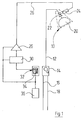
- 10 denotes a shower head as a whole, the via a feed line 12 with a mixing valve 14 is connected, which is shown as a single lever mixer is.
- the mixing valve 14 is the input side with a Cold water pipe 16 and a hot water pipe 18 connected.
- the shower head 10 includes next to the actual shower part 20 a control valve 22, which in the shower part 20 leading channel of the shower head housing 10 inserted is.
- the control valve 22 is shown as a solenoid valve. His solenoid 24 is connected via a line 26 with the Output of an amplifier 28 connected to the output a single-digit binary counter 30 is driven forth. The input of the binary counter 30 is with the output a button 32 which has a large actuator plate 34 has.
- An input of the button 32 is connected to the output of a Voltage source 36 connected.
- a Voltage source 36 can be about a battery, a photoelectric device, a Fuel cell or even with mains voltage operated Wet room suitable power supply act. This serves at the same time to the energy supply of the binary counter 30 and the amplifier 28 and any other electrical Components of the shower facility included in the drawing are not reproduced, such as indications of the operating state etc.
- the mixing valve 14 is different from the usual Mixing valves designed so that a throttled Connection between the cold water pipe and the feed pipe 12 also in the "closed position" of the mixing valve 14 remains. In this way, the inlet of the Control valve 22 always with pressurized water applied.
- the user sets the mixing valve 14 to the desired Throughput and the desired temperature. Then pressed he actuation plate 34 of the button 32, whereby the output signal of the one-digit binary counter changes. Accordingly, one obtains at the output of the amplifier 28 an activation signal for the actuating magnet 24, so that the control valve 22 opens. Now there is water the desired temperature and in the mixing valve 14 set amount of the shower part 20 delivered.
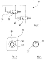
- FIG. 2 shows a modified control valve 22 which a pilot valve 38 and a main control valve 34 having.
- the pilot valve 38 is resilient in the closed position biased and can by energizing the solenoid 24 be brought into the open position.
- the main valve 40 is resiliently biased in the closed position and comprises a control cylinder 42, which with the work opening the pilot valve 38 is connected and at Pressurization the main control valve 40 counter moves the spring preload in the open position.
- control line 26 and the feed line 12 shown closely adjacent. In practice it will you can make these two lines to a one-piece handle Connect unit, z. B. by gluing, welding or mechanically (eg pushing in a flexible Control cable into a groove, in the outer surface the feed line 12 is provided).
- FIG. 3 shows an axial view of the connection end a practical embodiment of a control valve 22nd
- An inlet-side connecting piece 44 is made of metal injected into a valve housing 46.
- the connecting piece 44 has a standard thread, which comes in a standard thread the feed line 12 can be screwed.
- a connecting piece 44 adjacent nozzle 48 of the Housing carries an electrical contact 50, which in is resilient or formed by a spring in axial outward direction is biased.
- the contact 50 represents via a space-fixed counter contact, which in the drawing is not reproduced, the connection to line 26 ago.
- valve housing 46 Inside the valve housing 46 is the in FIG housed shown valve assembly.
- control valve 22 has a outlet side connecting piece 44, with a standard thread which is screwing on standard showerheads allowed.
- control valve 22 shown in Figure 3 can thus any standard showerheads are used in turn, it is ensured that in the feed line can not colonize viruses or bacteria.
- the control valve 22 shown in Figure 3 can also be use in conjunction with hand showers. In this case is then inside a flexible supply hose 52 designed as a flexible cable control line 26 arranged.
- the carried by the feed hose 52 conventional connection fittings are made of plastic material manufactured and carry flanges with contacts that with the contact 50 of the control valve 22 and a spatially fixed collaborate in the drawing, not shown in the drawing, the at the shower connection of the mixing valve 14 is provided.
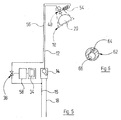
- FIG. 5 shows a modified embodiment with fluidic actuation of the control valve 22. Parts the shower device, with reference to Figure 1 have already been explained are again with the same reference numerals and will not be repeated below described in detail.
- the control valve 22 now has a control cylinder 54, the logically corresponds to the actuating cylinder 42 of Figure 2.
- the pilot valve 38 is now no solenoid valve but a mechanically actuated Valve.
- the actuation is carried out by the actuator plate 34 ago, via a two-position gearbox 58 mechanically connected to the actuator of the pilot valve 38 is.
- the two-position gear 58 may be similar as of the adjustment of pen refills known here. Every time you press its input element the position of the output member between two changed different end positions.
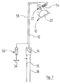
- FIG. 7 in the mixing valve adjacent end of the control line 56 a master cylinder 60 provide.
- the control line 56 and the work spaces the actuating cylinder 54 and the master cylinder 60th are with a closed volume of an actuating fluid filled, the water or even a hydraulic oil can be.
- the actuation of the main valve 40 takes place by a displaceable actuator 34, which mechanically coupled to the piston of the master cylinder 60 is.
- FIG. 6 shows a transverse section through a two-channel tube made of extruded aluminum or an extruded aluminum alloy or a extruded plastic material can be made.
- This dual-channel tube 62 has a control channel 64, which forms the control line 56, and a water channel 66, which forms the feed line 12.
- control valve 22 shown in FIG instead of the control valve 22 shown in FIG also a monostable solenoid valve can be used. This is preferably used when the voltage source 36 is a power supply or such is fed.
- control valve 22 a bistable solenoid valve is used.
- buttons 32 and any other probes can be used by a user for targeted delivery of an electrical Signals can be initiated.
- These include in First and foremost, IR light barriers, optical sensors, others Current sensors such as radar sensors, ultrasonic sensors etc..
Landscapes
- Engineering & Computer Science (AREA)
- Hydrology & Water Resources (AREA)
- Water Supply & Treatment (AREA)
- Public Health (AREA)
- Health & Medical Sciences (AREA)
- Life Sciences & Earth Sciences (AREA)
- Automation & Control Theory (AREA)
- Physics & Mathematics (AREA)
- General Physics & Mathematics (AREA)
- Bathtubs, Showers, And Their Attachments (AREA)
- Domestic Plumbing Installations (AREA)
- Devices That Are Associated With Refrigeration Equipment (AREA)
- Vehicle Body Suspensions (AREA)
- Massaging Devices (AREA)
- Catching Or Destruction (AREA)
Abstract
Description
- Figur 1
- eine schematische Darstellung einer Duscheinrichtung;
- Figur 2
- ein Blockschaltbild einer abgewandelten Steuerventilanordnung, die anstelle eines in Figur 1 gezeigten Duschkopf-Steuerventils verwendbar ist;
- Figur 3
- eine axiale Aufsicht auf ein praktisches Ausführungsbeispiel einer Steuerventilanordnung gemäß Figur 2;
- Figur 4
- einen transversalen Schnitt durch einen flexiblen Schlauch mit integrierter Steuerleitung für ein Duschkopf-Steuerventil;
- Figur 5
- eine ähnliche Ansicht wie Figur 1, in welcher ein fluidbetätigtes Duschkopf-Steuerventil wiedergegeben ist;
- Figur 6
- einen transversalen Schnitt durch eine bevorzugte Ausführung einer doppelten Verbindungsleitung zum Duschkopf, welche einen Speisewasserkanal und einen Steuerdruckkanal aufweist; und
- Figur 7
- eine ähnliche Ansicht wie Figur 1, in welcher ein hydromechanisch betätigtes Duschkopf-Steuerventil dargestellt ist.
Claims (8)
- Duscheinrichtung mit einem Duschkopf (10), einer zu diesem führenden Speiseleitung (12) und einer mit dieser verbundenen vom Duschkopf (10) beabstandeten Steuerarmatur (14), dadurch gekennzeichnet, daß die Speiseleitung (12) in der Nachbarschaft von deren duschkopfseitigen Ende ein fernbedientes Steuerventil (22) aufweist.
- Duscheinrichtung nach Anspruch 1, dadurch gekennzeichnet, daß ein Betätigungsteil (34) für das Steuerventil (22) in der Nachbarschaft der Steuerarmatur (14) angeordnet oder in diese integriert ist.
- Duscheinrichtung nach Anspruch 1 oder 2, dadurch gekennzeichnet, daß das Steuerventil (22) einen Stellmagneten (24) umfaßt.
- Duscheinrichtung nach Anspruch 3, dadurch gekennzeichnet, daß der Stellmagnet (24) ein Vorsteuerventil (38) betätigt, dessen Arbeitsöffnung mit einem Stellzylinder (42) eines Hauptsteuerventils (40) verbunden ist.
- Duscheinrichtung nach Anspruch 1 oder 2, dadurch gekennzeichnet, daß das Steuerventil (22) einen Betätigungszylinder (54) aufweist, der über eine Steuerleitung (56) mit einem Vorsteuerventil (38) oder einem Geberzylinder (60) verbunden ist, welche durch das Betätigungsteil (34) betätigbar sind.
- Duscheinrichtung nach Anspruch 5, dadurch gekennzeichnet, daß die Steuerleitung (56) und die Speiseleitung (12) zu einer Einheit zusammengefaßt sind.
- Duscheinrichtung nach Anspruch 6, dadurch gekennzeichnet, daß die Steuerleitung (56) und die Speiseleitung (12) zumindest teilweise durch ein Rohr (62) gebildet sind, welches zwei Kanäle (64, 68) aufweist.
- Duscheinrichtung nach Anspruch 1 oder 2, dadurch gekennzeichnet, daß ein Stellteil des Steuerventiles (22) über eine mechanische oder fluidische Kraftübertragunsstrecke (54, 56, 60) mit einem der Mischarmatur (14) benachbarten Betätigungsglied (34) verbunden ist.
Applications Claiming Priority (2)
| Application Number | Priority Date | Filing Date | Title |
|---|---|---|---|
| DE20315306U | 2003-10-01 | ||
| DE20315306U DE20315306U1 (de) | 2003-10-01 | 2003-10-01 | Duscheinrichtung |
Publications (3)
| Publication Number | Publication Date |
|---|---|
| EP1520629A2 true EP1520629A2 (de) | 2005-04-06 |
| EP1520629A3 EP1520629A3 (de) | 2005-04-27 |
| EP1520629B1 EP1520629B1 (de) | 2006-06-14 |
Family
ID=34306458
Family Applications (1)
| Application Number | Title | Priority Date | Filing Date |
|---|---|---|---|
| EP04022259A Expired - Lifetime EP1520629B1 (de) | 2003-10-01 | 2004-09-18 | Duscheinrichtung |
Country Status (4)
| Country | Link |
|---|---|
| US (1) | US20050082396A1 (de) |
| EP (1) | EP1520629B1 (de) |
| AT (1) | ATE329695T1 (de) |
| DE (2) | DE20315306U1 (de) |
Families Citing this family (3)
| Publication number | Priority date | Publication date | Assignee | Title |
|---|---|---|---|---|
| TR201617045A2 (tr) * | 2016-11-23 | 2017-05-22 | Goekmen Senerler | Sıcaklık ayarı yapabilen duş başlığı. |
| DE202021103647U1 (de) * | 2021-07-07 | 2022-10-18 | Neoperl GmbH | Sanitäre Anordnung |
| US12565764B2 (en) | 2023-05-31 | 2026-03-03 | Fortune Brands Water Innovations | Retrofit electronic plumbing system |
Family Cites Families (20)
| Publication number | Priority date | Publication date | Assignee | Title |
|---|---|---|---|---|
| US4426745A (en) * | 1981-06-13 | 1984-01-24 | Walker Crosweller & Company Ltd. | Ablutionary shower systems |
| AU599845B2 (en) * | 1987-10-26 | 1990-07-26 | Graeme Charles Dodds | An irrigation system |
| US5121511A (en) * | 1989-11-27 | 1992-06-16 | Matsushita Electric Works, Ltd. | Shower device |
| US5152465A (en) * | 1991-06-10 | 1992-10-06 | Calabro Daniel J | Shower flow controller |
| US5333785A (en) * | 1991-12-19 | 1994-08-02 | Dodds Graeme C | Wireless irrigation system |
| US5220914A (en) * | 1992-10-26 | 1993-06-22 | Thompson Thomas W | Plaque dislodging apparatus |
| US5445181A (en) * | 1994-09-15 | 1995-08-29 | Kohler Co. | Mixing valve |
| DE19501014A1 (de) * | 1995-01-14 | 1996-07-18 | Grohe Armaturen Friedrich | Automatische Duschensteuerung |
| US5839658A (en) * | 1996-09-27 | 1998-11-24 | Sarver; Larry C. | Method of retrofitting irrigation control systems |
| US5813655A (en) * | 1996-10-11 | 1998-09-29 | Pinchott; Gordon A. | Remote-control on/off valve |
| US5918811A (en) * | 1997-06-12 | 1999-07-06 | Speakman Company | Showerhead with variable spray patterns and internal shutoff valve |
| AUPP333598A0 (en) * | 1998-05-05 | 1998-05-28 | Watergate Enviroshower Pty. Ltd. | Control apparatus for showers |
| US6149071A (en) * | 1998-06-10 | 2000-11-21 | Global Metering Solutions, Llc | Flow control system for spray applications |
| JP2000139549A (ja) * | 1998-11-10 | 2000-05-23 | Ohiro Seisakusho:Kk | 自動洗髪機 |
| US6401742B1 (en) * | 1999-11-08 | 2002-06-11 | Dean L. Cramer | Moisture sensor and irrigation control system |
| EP1313567A2 (de) * | 2000-01-28 | 2003-05-28 | Pierre Tournier | Hygienischer brausekopf mit lösbarem diffusor |
| US6438770B1 (en) * | 2000-07-25 | 2002-08-27 | Invent Resources, Inc. | Electronically-controlled shower system |
| US6565018B1 (en) * | 2001-02-09 | 2003-05-20 | Degeyter John D | Shower flow control device |
| US6550697B2 (en) * | 2001-08-28 | 2003-04-22 | Globe Union Industrial Corp. | Shower head assembly |
| US6807983B1 (en) * | 2003-05-06 | 2004-10-26 | Kohler Co. | Valve assembly with swivel escutcheon |
-
2003
- 2003-10-01 DE DE20315306U patent/DE20315306U1/de not_active Expired - Lifetime
-
2004
- 2004-09-18 EP EP04022259A patent/EP1520629B1/de not_active Expired - Lifetime
- 2004-09-18 DE DE502004000757T patent/DE502004000757D1/de not_active Expired - Fee Related
- 2004-09-18 AT AT04022259T patent/ATE329695T1/de not_active IP Right Cessation
- 2004-09-27 US US10/951,010 patent/US20050082396A1/en not_active Abandoned
Also Published As
| Publication number | Publication date |
|---|---|
| EP1520629A3 (de) | 2005-04-27 |
| DE502004000757D1 (de) | 2006-07-27 |
| US20050082396A1 (en) | 2005-04-21 |
| EP1520629B1 (de) | 2006-06-14 |
| DE20315306U1 (de) | 2005-03-17 |
| ATE329695T1 (de) | 2006-07-15 |
Similar Documents
| Publication | Publication Date | Title |
|---|---|---|
| EP2218840B1 (de) | Sanitärarmatur mit Joysticksteuerung | |
| EP0313913A2 (de) | Mischvorrichtung | |
| DE19834151C1 (de) | Ventil für Warmwasseranlagen | |
| DE102013001584A1 (de) | Sanitäranordnung | |
| DE19623104C2 (de) | Als Einhebelmischer ausgebildete Sanitärarmatur | |
| EP1853769A1 (de) | Brauseeinrichtung | |
| DE10204737B4 (de) | Vorrichtung zum Spülen und Reinigen einer Rohrleitung, insbesondere einer Trinkwasserleitung | |
| DE4431127C2 (de) | Sanitärventil mit einem Magnetventil | |
| EP1520629B1 (de) | Duscheinrichtung | |
| EP1018063B1 (de) | Regler | |
| DE4108458C2 (de) | Sanitärarmatur | |
| DE102013113591A1 (de) | Wasserschalteinheit | |
| EP2543780A1 (de) | Brausenmodul und Duschsystem mit elektronischer Steuerung | |
| DE102011003864B4 (de) | Einsatz für den Wasserauslass aus einer Sanitärarmatur | |
| DE2012827C3 (de) | Ventilaufsatz | |
| DE19622171C1 (de) | Vorrichtung zur Steuerung der Wasserausgabe an einem Waschbecken | |
| DE2252395C3 (de) | Umschalter für ein System Wanne-Brause | |
| DE2912583A1 (de) | Sanitaere mischbatterie | |
| DE102005042701A1 (de) | Anordnung zum Ein- oder Ausschalten des Wasserflusses einer Bewässerungsanlage | |
| DE102013011302B4 (de) | Verfahren für ein automatisch und kombiniert wirkendes Stoffeinbringungs-, Dosierungs- und Antriebssystem. | |
| DE3744396C2 (de) | ||
| DE4141172B4 (de) | Vorrichtung zum Umstellen eines Ventilgliedes an einer Sanitärarmatur | |
| DE3439235C2 (de) | ||
| EP1895062A2 (de) | Fernbedienbare Handbrause | |
| EP2463445A1 (de) | Sanitäre Ventileinrichtung |
Legal Events
| Date | Code | Title | Description |
|---|---|---|---|
| PUAI | Public reference made under article 153(3) epc to a published international application that has entered the european phase |
Free format text: ORIGINAL CODE: 0009012 |
|
| PUAL | Search report despatched |
Free format text: ORIGINAL CODE: 0009013 |
|
| AK | Designated contracting states |
Kind code of ref document: A2 Designated state(s): AT BE BG CH CY CZ DE DK EE ES FI FR GB GR HU IE IT LI LU MC NL PL PT RO SE SI SK TR |
|
| AX | Request for extension of the european patent |
Extension state: AL HR LT LV MK |
|
| AK | Designated contracting states |
Kind code of ref document: A3 Designated state(s): AT BE BG CH CY CZ DE DK EE ES FI FR GB GR HU IE IT LI LU MC NL PL PT RO SE SI SK TR |
|
| AX | Request for extension of the european patent |
Extension state: AL HR LT LV MK |
|
| 17P | Request for examination filed |
Effective date: 20051027 |
|
| GRAP | Despatch of communication of intention to grant a patent |
Free format text: ORIGINAL CODE: EPIDOSNIGR1 |
|
| AKX | Designation fees paid |
Designated state(s): AT BE BG CH CY CZ DE DK EE ES FI FR GB GR HU IE IT LI LU MC NL PL PT RO SE SI SK TR |
|
| GRAS | Grant fee paid |
Free format text: ORIGINAL CODE: EPIDOSNIGR3 |
|
| GRAA | (expected) grant |
Free format text: ORIGINAL CODE: 0009210 |
|
| AK | Designated contracting states |
Kind code of ref document: B1 Designated state(s): AT BE BG CH CY CZ DE DK EE ES FI FR GB GR HU IE IT LI LU MC NL PL PT RO SE SI SK TR |
|
| PG25 | Lapsed in a contracting state [announced via postgrant information from national office to epo] |
Ref country code: IT Free format text: LAPSE BECAUSE OF FAILURE TO SUBMIT A TRANSLATION OF THE DESCRIPTION OR TO PAY THE FEE WITHIN THE PRESCRIBED TIME-LIMIT;WARNING: LAPSES OF ITALIAN PATENTS WITH EFFECTIVE DATE BEFORE 2007 MAY HAVE OCCURRED AT ANY TIME BEFORE 2007. THE CORRECT EFFECTIVE DATE MAY BE DIFFERENT FROM THE ONE RECORDED. Effective date: 20060614 Ref country code: RO Free format text: LAPSE BECAUSE OF FAILURE TO SUBMIT A TRANSLATION OF THE DESCRIPTION OR TO PAY THE FEE WITHIN THE PRESCRIBED TIME-LIMIT Effective date: 20060614 Ref country code: IE Free format text: LAPSE BECAUSE OF FAILURE TO SUBMIT A TRANSLATION OF THE DESCRIPTION OR TO PAY THE FEE WITHIN THE PRESCRIBED TIME-LIMIT Effective date: 20060614 Ref country code: PL Free format text: LAPSE BECAUSE OF FAILURE TO SUBMIT A TRANSLATION OF THE DESCRIPTION OR TO PAY THE FEE WITHIN THE PRESCRIBED TIME-LIMIT Effective date: 20060614 Ref country code: FI Free format text: LAPSE BECAUSE OF FAILURE TO SUBMIT A TRANSLATION OF THE DESCRIPTION OR TO PAY THE FEE WITHIN THE PRESCRIBED TIME-LIMIT Effective date: 20060614 Ref country code: NL Free format text: LAPSE BECAUSE OF FAILURE TO SUBMIT A TRANSLATION OF THE DESCRIPTION OR TO PAY THE FEE WITHIN THE PRESCRIBED TIME-LIMIT Effective date: 20060614 Ref country code: CZ Free format text: LAPSE BECAUSE OF FAILURE TO SUBMIT A TRANSLATION OF THE DESCRIPTION OR TO PAY THE FEE WITHIN THE PRESCRIBED TIME-LIMIT Effective date: 20060614 Ref country code: SK Free format text: LAPSE BECAUSE OF FAILURE TO SUBMIT A TRANSLATION OF THE DESCRIPTION OR TO PAY THE FEE WITHIN THE PRESCRIBED TIME-LIMIT Effective date: 20060614 Ref country code: SI Free format text: LAPSE BECAUSE OF FAILURE TO SUBMIT A TRANSLATION OF THE DESCRIPTION OR TO PAY THE FEE WITHIN THE PRESCRIBED TIME-LIMIT Effective date: 20060614 Ref country code: GB Free format text: LAPSE BECAUSE OF FAILURE TO SUBMIT A TRANSLATION OF THE DESCRIPTION OR TO PAY THE FEE WITHIN THE PRESCRIBED TIME-LIMIT Effective date: 20060614 |
|
| REG | Reference to a national code |
Ref country code: GB Ref legal event code: FG4D Free format text: NOT ENGLISH |
|
| REG | Reference to a national code |
Ref country code: CH Ref legal event code: EP |
|
| REG | Reference to a national code |
Ref country code: IE Ref legal event code: FG4D Free format text: LANGUAGE OF EP DOCUMENT: GERMAN |
|
| REF | Corresponds to: |
Ref document number: 502004000757 Country of ref document: DE Date of ref document: 20060727 Kind code of ref document: P |
|
| PG25 | Lapsed in a contracting state [announced via postgrant information from national office to epo] |
Ref country code: DK Free format text: LAPSE BECAUSE OF FAILURE TO SUBMIT A TRANSLATION OF THE DESCRIPTION OR TO PAY THE FEE WITHIN THE PRESCRIBED TIME-LIMIT Effective date: 20060914 Ref country code: SE Free format text: LAPSE BECAUSE OF FAILURE TO SUBMIT A TRANSLATION OF THE DESCRIPTION OR TO PAY THE FEE WITHIN THE PRESCRIBED TIME-LIMIT Effective date: 20060914 |
|
| PG25 | Lapsed in a contracting state [announced via postgrant information from national office to epo] |
Ref country code: ES Free format text: LAPSE BECAUSE OF FAILURE TO SUBMIT A TRANSLATION OF THE DESCRIPTION OR TO PAY THE FEE WITHIN THE PRESCRIBED TIME-LIMIT Effective date: 20060925 |
|
| REG | Reference to a national code |
Ref country code: CH Ref legal event code: NV Representative=s name: FREI PATENTANWALTSBUERO |
|
| PG25 | Lapsed in a contracting state [announced via postgrant information from national office to epo] |
Ref country code: MC Free format text: LAPSE BECAUSE OF NON-PAYMENT OF DUE FEES Effective date: 20060930 Ref country code: BE Free format text: LAPSE BECAUSE OF NON-PAYMENT OF DUE FEES Effective date: 20060930 |
|
| PG25 | Lapsed in a contracting state [announced via postgrant information from national office to epo] |
Ref country code: PT Free format text: LAPSE BECAUSE OF FAILURE TO SUBMIT A TRANSLATION OF THE DESCRIPTION OR TO PAY THE FEE WITHIN THE PRESCRIBED TIME-LIMIT Effective date: 20061114 |
|
| NLV1 | Nl: lapsed or annulled due to failure to fulfill the requirements of art. 29p and 29m of the patents act | ||
| GBV | Gb: ep patent (uk) treated as always having been void in accordance with gb section 77(7)/1977 [no translation filed] |
Effective date: 20060614 |
|
| REG | Reference to a national code |
Ref country code: IE Ref legal event code: FD4D |
|
| PLBE | No opposition filed within time limit |
Free format text: ORIGINAL CODE: 0009261 |
|
| STAA | Information on the status of an ep patent application or granted ep patent |
Free format text: STATUS: NO OPPOSITION FILED WITHIN TIME LIMIT |
|
| EN | Fr: translation not filed | ||
| 26N | No opposition filed |
Effective date: 20070315 |
|
| BERE | Be: lapsed |
Owner name: AQUIS SANITAR A.G. Effective date: 20060930 |
|
| PG25 | Lapsed in a contracting state [announced via postgrant information from national office to epo] |
Ref country code: GR Free format text: LAPSE BECAUSE OF FAILURE TO SUBMIT A TRANSLATION OF THE DESCRIPTION OR TO PAY THE FEE WITHIN THE PRESCRIBED TIME-LIMIT Effective date: 20060915 Ref country code: FR Free format text: LAPSE BECAUSE OF FAILURE TO SUBMIT A TRANSLATION OF THE DESCRIPTION OR TO PAY THE FEE WITHIN THE PRESCRIBED TIME-LIMIT Effective date: 20070309 |
|
| PG25 | Lapsed in a contracting state [announced via postgrant information from national office to epo] |
Ref country code: EE Free format text: LAPSE BECAUSE OF FAILURE TO SUBMIT A TRANSLATION OF THE DESCRIPTION OR TO PAY THE FEE WITHIN THE PRESCRIBED TIME-LIMIT Effective date: 20060614 Ref country code: BG Free format text: LAPSE BECAUSE OF FAILURE TO SUBMIT A TRANSLATION OF THE DESCRIPTION OR TO PAY THE FEE WITHIN THE PRESCRIBED TIME-LIMIT Effective date: 20060914 |
|
| PG25 | Lapsed in a contracting state [announced via postgrant information from national office to epo] |
Ref country code: HU Free format text: LAPSE BECAUSE OF FAILURE TO SUBMIT A TRANSLATION OF THE DESCRIPTION OR TO PAY THE FEE WITHIN THE PRESCRIBED TIME-LIMIT Effective date: 20061215 Ref country code: TR Free format text: LAPSE BECAUSE OF FAILURE TO SUBMIT A TRANSLATION OF THE DESCRIPTION OR TO PAY THE FEE WITHIN THE PRESCRIBED TIME-LIMIT Effective date: 20060614 Ref country code: LU Free format text: LAPSE BECAUSE OF NON-PAYMENT OF DUE FEES Effective date: 20060918 |
|
| PGFP | Annual fee paid to national office [announced via postgrant information from national office to epo] |
Ref country code: CH Payment date: 20080917 Year of fee payment: 5 |
|
| PG25 | Lapsed in a contracting state [announced via postgrant information from national office to epo] |
Ref country code: FR Free format text: LAPSE BECAUSE OF FAILURE TO SUBMIT A TRANSLATION OF THE DESCRIPTION OR TO PAY THE FEE WITHIN THE PRESCRIBED TIME-LIMIT Effective date: 20060614 Ref country code: CY Free format text: LAPSE BECAUSE OF FAILURE TO SUBMIT A TRANSLATION OF THE DESCRIPTION OR TO PAY THE FEE WITHIN THE PRESCRIBED TIME-LIMIT Effective date: 20060614 |
|
| PGFP | Annual fee paid to national office [announced via postgrant information from national office to epo] |
Ref country code: AT Payment date: 20080918 Year of fee payment: 5 |
|
| PGFP | Annual fee paid to national office [announced via postgrant information from national office to epo] |
Ref country code: DE Payment date: 20081128 Year of fee payment: 5 |
|
| REG | Reference to a national code |
Ref country code: CH Ref legal event code: PL |
|
| PG25 | Lapsed in a contracting state [announced via postgrant information from national office to epo] |
Ref country code: AT Free format text: LAPSE BECAUSE OF NON-PAYMENT OF DUE FEES Effective date: 20090918 |
|
| PG25 | Lapsed in a contracting state [announced via postgrant information from national office to epo] |
Ref country code: DE Free format text: LAPSE BECAUSE OF NON-PAYMENT OF DUE FEES Effective date: 20100401 |
|
| PG25 | Lapsed in a contracting state [announced via postgrant information from national office to epo] |
Ref country code: LI Free format text: LAPSE BECAUSE OF NON-PAYMENT OF DUE FEES Effective date: 20090930 Ref country code: CH Free format text: LAPSE BECAUSE OF NON-PAYMENT OF DUE FEES Effective date: 20090930 |