EP1519829B1 - Procede et dispositif destines a l'application automatique d'un film de peinture sur des pieces de carrosserie et film de peinture composite compatible avec l'automatisation - Google Patents
Procede et dispositif destines a l'application automatique d'un film de peinture sur des pieces de carrosserie et film de peinture composite compatible avec l'automatisation Download PDFInfo
- Publication number
- EP1519829B1 EP1519829B1 EP03730056A EP03730056A EP1519829B1 EP 1519829 B1 EP1519829 B1 EP 1519829B1 EP 03730056 A EP03730056 A EP 03730056A EP 03730056 A EP03730056 A EP 03730056A EP 1519829 B1 EP1519829 B1 EP 1519829B1
- Authority
- EP
- European Patent Office
- Prior art keywords
- paint film
- film
- protective strip
- film composite
- application tool
- Prior art date
- Legal status (The legal status is an assumption and is not a legal conclusion. Google has not performed a legal analysis and makes no representation as to the accuracy of the status listed.)
- Expired - Lifetime
Links
- 239000002131 composite material Substances 0.000 title claims abstract description 191
- 238000000034 method Methods 0.000 title claims abstract description 59
- 230000001681 protective effect Effects 0.000 claims abstract description 127
- 239000000853 adhesive Substances 0.000 claims abstract description 31
- 230000001070 adhesive effect Effects 0.000 claims abstract description 27
- 239000003973 paint Substances 0.000 claims description 166
- 238000004804 winding Methods 0.000 claims description 33
- 230000008569 process Effects 0.000 claims description 30
- 238000012546 transfer Methods 0.000 claims description 6
- 239000002313 adhesive film Substances 0.000 claims description 4
- 238000013459 approach Methods 0.000 claims description 4
- 239000011248 coating agent Substances 0.000 claims description 4
- 238000000576 coating method Methods 0.000 claims description 4
- 230000002250 progressing effect Effects 0.000 claims description 4
- 239000000463 material Substances 0.000 claims description 2
- 208000029154 Narrow face Diseases 0.000 claims 2
- 230000001464 adherent effect Effects 0.000 claims 2
- 239000010408 film Substances 0.000 description 324
- 210000003323 beak Anatomy 0.000 description 82
- 239000011888 foil Substances 0.000 description 25
- 239000004922 lacquer Substances 0.000 description 18
- 239000006228 supernatant Substances 0.000 description 16
- 239000010410 layer Substances 0.000 description 15
- 238000006073 displacement reaction Methods 0.000 description 13
- 230000008901 benefit Effects 0.000 description 10
- 230000002745 absorbent Effects 0.000 description 8
- 239000002250 absorbent Substances 0.000 description 8
- 239000004820 Pressure-sensitive adhesive Substances 0.000 description 6
- 238000013461 design Methods 0.000 description 6
- 206010052428 Wound Diseases 0.000 description 5
- 208000027418 Wounds and injury Diseases 0.000 description 5
- 239000012790 adhesive layer Substances 0.000 description 5
- 210000002414 leg Anatomy 0.000 description 5
- 239000002356 single layer Substances 0.000 description 5
- 230000035882 stress Effects 0.000 description 5
- 206010040954 Skin wrinkling Diseases 0.000 description 4
- 238000005452 bending Methods 0.000 description 4
- 239000002245 particle Substances 0.000 description 4
- 238000003825 pressing Methods 0.000 description 4
- 230000008859 change Effects 0.000 description 3
- 230000000694 effects Effects 0.000 description 3
- 239000011521 glass Substances 0.000 description 3
- 238000002360 preparation method Methods 0.000 description 3
- 238000003860 storage Methods 0.000 description 3
- 230000004888 barrier function Effects 0.000 description 2
- 230000015572 biosynthetic process Effects 0.000 description 2
- 230000008878 coupling Effects 0.000 description 2
- 238000010168 coupling process Methods 0.000 description 2
- 238000005859 coupling reaction Methods 0.000 description 2
- 239000000428 dust Substances 0.000 description 2
- 238000005421 electrostatic potential Methods 0.000 description 2
- 230000005484 gravity Effects 0.000 description 2
- 210000000629 knee joint Anatomy 0.000 description 2
- 238000004519 manufacturing process Methods 0.000 description 2
- 230000002829 reductive effect Effects 0.000 description 2
- 239000002699 waste material Substances 0.000 description 2
- 210000000707 wrist Anatomy 0.000 description 2
- FGRBYDKOBBBPOI-UHFFFAOYSA-N 10,10-dioxo-2-[4-(N-phenylanilino)phenyl]thioxanthen-9-one Chemical compound O=C1c2ccccc2S(=O)(=O)c2ccc(cc12)-c1ccc(cc1)N(c1ccccc1)c1ccccc1 FGRBYDKOBBBPOI-UHFFFAOYSA-N 0.000 description 1
- 229920001817 Agar Polymers 0.000 description 1
- 208000006820 Arthralgia Diseases 0.000 description 1
- 101100008050 Caenorhabditis elegans cut-6 gene Proteins 0.000 description 1
- 208000034656 Contusions Diseases 0.000 description 1
- 241000446313 Lamella Species 0.000 description 1
- 208000000491 Tendinopathy Diseases 0.000 description 1
- 206010043255 Tendonitis Diseases 0.000 description 1
- 238000009825 accumulation Methods 0.000 description 1
- 230000009471 action Effects 0.000 description 1
- 238000004026 adhesive bonding Methods 0.000 description 1
- 230000002411 adverse Effects 0.000 description 1
- 230000032683 aging Effects 0.000 description 1
- 238000006243 chemical reaction Methods 0.000 description 1
- 238000004140 cleaning Methods 0.000 description 1
- 238000010276 construction Methods 0.000 description 1
- 238000005520 cutting process Methods 0.000 description 1
- 230000007423 decrease Effects 0.000 description 1
- 238000001514 detection method Methods 0.000 description 1
- 238000007598 dipping method Methods 0.000 description 1
- 238000000605 extraction Methods 0.000 description 1
- 238000009950 felting Methods 0.000 description 1
- 239000003292 glue Substances 0.000 description 1
- 231100001261 hazardous Toxicity 0.000 description 1
- 230000008821 health effect Effects 0.000 description 1
- 238000007373 indentation Methods 0.000 description 1
- 210000003127 knee Anatomy 0.000 description 1
- 230000000670 limiting effect Effects 0.000 description 1
- 238000012423 maintenance Methods 0.000 description 1
- 238000011089 mechanical engineering Methods 0.000 description 1
- 238000004806 packaging method and process Methods 0.000 description 1
- 230000036961 partial effect Effects 0.000 description 1
- 230000002093 peripheral effect Effects 0.000 description 1
- 238000012545 processing Methods 0.000 description 1
- 230000000750 progressive effect Effects 0.000 description 1
- 230000000284 resting effect Effects 0.000 description 1
- 238000009751 slip forming Methods 0.000 description 1
- 239000007787 solid Substances 0.000 description 1
- 125000006850 spacer group Chemical group 0.000 description 1
- 238000003892 spreading Methods 0.000 description 1
- 230000007480 spreading Effects 0.000 description 1
- 238000010408 sweeping Methods 0.000 description 1
- 201000004415 tendinitis Diseases 0.000 description 1
- 239000010409 thin film Substances 0.000 description 1
- 238000013519 translation Methods 0.000 description 1
- 238000013022 venting Methods 0.000 description 1
Images


Classifications
-
- B—PERFORMING OPERATIONS; TRANSPORTING
- B29—WORKING OF PLASTICS; WORKING OF SUBSTANCES IN A PLASTIC STATE IN GENERAL
- B29C—SHAPING OR JOINING OF PLASTICS; SHAPING OF MATERIAL IN A PLASTIC STATE, NOT OTHERWISE PROVIDED FOR; AFTER-TREATMENT OF THE SHAPED PRODUCTS, e.g. REPAIRING
- B29C63/00—Lining or sheathing, i.e. applying preformed layers or sheathings of plastics; Apparatus therefor
- B29C63/02—Lining or sheathing, i.e. applying preformed layers or sheathings of plastics; Apparatus therefor using sheet or web-like material
- B29C2063/027—Lining or sheathing, i.e. applying preformed layers or sheathings of plastics; Apparatus therefor using sheet or web-like material applied by a squeegee
-
- B—PERFORMING OPERATIONS; TRANSPORTING
- B29—WORKING OF PLASTICS; WORKING OF SUBSTANCES IN A PLASTIC STATE IN GENERAL
- B29C—SHAPING OR JOINING OF PLASTICS; SHAPING OF MATERIAL IN A PLASTIC STATE, NOT OTHERWISE PROVIDED FOR; AFTER-TREATMENT OF THE SHAPED PRODUCTS, e.g. REPAIRING
- B29C63/00—Lining or sheathing, i.e. applying preformed layers or sheathings of plastics; Apparatus therefor
- B29C63/0047—Preventing air-inclusions
-
- B—PERFORMING OPERATIONS; TRANSPORTING
- B29—WORKING OF PLASTICS; WORKING OF SUBSTANCES IN A PLASTIC STATE IN GENERAL
- B29L—INDEXING SCHEME ASSOCIATED WITH SUBCLASS B29C, RELATING TO PARTICULAR ARTICLES
- B29L2031/00—Other particular articles
- B29L2031/30—Vehicles, e.g. ships or aircraft, or body parts thereof
- B29L2031/3055—Cars
-
- Y—GENERAL TAGGING OF NEW TECHNOLOGICAL DEVELOPMENTS; GENERAL TAGGING OF CROSS-SECTIONAL TECHNOLOGIES SPANNING OVER SEVERAL SECTIONS OF THE IPC; TECHNICAL SUBJECTS COVERED BY FORMER USPC CROSS-REFERENCE ART COLLECTIONS [XRACs] AND DIGESTS
- Y10—TECHNICAL SUBJECTS COVERED BY FORMER USPC
- Y10T—TECHNICAL SUBJECTS COVERED BY FORMER US CLASSIFICATION
- Y10T156/00—Adhesive bonding and miscellaneous chemical manufacture
- Y10T156/11—Methods of delaminating, per se; i.e., separating at bonding face
- Y10T156/1105—Delaminating process responsive to feed or shape at delamination
-
- Y—GENERAL TAGGING OF NEW TECHNOLOGICAL DEVELOPMENTS; GENERAL TAGGING OF CROSS-SECTIONAL TECHNOLOGIES SPANNING OVER SEVERAL SECTIONS OF THE IPC; TECHNICAL SUBJECTS COVERED BY FORMER USPC CROSS-REFERENCE ART COLLECTIONS [XRACs] AND DIGESTS
- Y10—TECHNICAL SUBJECTS COVERED BY FORMER USPC
- Y10T—TECHNICAL SUBJECTS COVERED BY FORMER US CLASSIFICATION
- Y10T156/00—Adhesive bonding and miscellaneous chemical manufacture
- Y10T156/19—Delaminating means
- Y10T156/1978—Delaminating bending means
- Y10T156/1983—Poking delaminating means
Definitions
- the invention relates to a method and a device for the automated application of paint film on body parts and an automated designed paint film composite.
- the invention is based on a method for automated application of self-adhesive film on body parts according to the preamble of claim 1 and of a corresponding device according to claim 15, both of which, for example, from DE 196 42 831 A1 as known.
- DE 198 09 515 A1 are mentioned, which in the aspect of interest here with the first-mentioned document essentially in terms of content.
- the paint film composite is known as the genus on the DE 195 32 998 A1 referred to, which is reproduced in the preamble of claim 33.
- the initially mentioned in connection with the paint film document DE 195 32 998 A1 shows a flat blank of such a self-adhesive paint film to be applied to the frame spar of a window frame bubble and wrinkle-free.
- To avoid trapped air bubbles (bubbles) between the body and paint film latter is provided at least in hazardous areas nationwide with a plurality of rastered arranged, micro-fine vents. Any air pockets can easily escape through them. Because the vents are so small, they do not interfere - at least initially - the appearance of the applied with the paint film body part.
- the gridded arranged vents should also increase the spatial adaptability of the paint film and reduce the risk of wrinkling.
- the paint film blank provided on the underside with a very intensively adhesive pressure-sensitive adhesive layer in the ready-to-use condition constitutes a three-layer film composite in which the paint film blank is pasted over with a protective film or protective paper both on the underside and on the high-gloss visible side.
- the underside protective paper is provided on the contact side to the pressure-sensitive adhesive layer of the paint film blank with a non-stick coating, so that it can be solved relatively easily and especially without tearing from the intensely adhesive pressure-sensitive adhesive layer of the paint film.
- the top-side protective paper is provided on the contact side to the outside of the paint film blank with a low-adhesion pressure-sensitive adhesive, so that this protective paper can be easily solved by the paint film.
- the underside or adhesive-side protective foil strip is completely removed so that the adhesive side of the lacquer foil is exposed.
- the on the visible side of the paint film still adhering protective film strip is shown in the above DE 195 32 998 A1 set back relative to the end of the paint film, so that the remaining film composite must be handled on the paint film blank itself.
- the hand application of paint films on the vehicle body has several disadvantages.
- the paint films can be placed only with a low accuracy, which leads to frequent rework.
- no exact reference mark for aligning the foil blank by eye is present on the body.
- the paint film can either sit slightly crooked, so that the tight margins are unfavorable or the film cut sits too high or too low.
- a different height position of the paint films is very disturbing in an application to the two immediately adjacent window frame spars in the region of the center pillar.
- a further disadvantage is that even with a smooth course of the paint film on the body and strong pressing the paint film to the frame spar nonetheless frequently air pockets occur between the two, but often shows only after a certain delay.
- the air adsorbed on the adhesive layer is first trapped in microfine and inconspicuous blisters. This primary air slowly migrates in the adhesive layer and accumulates to larger bubbles, which are the paint film bulge locally. These subsequently resulting bubbles must be eliminated by reworking, ie by targeted needle pricks. It has also been found that the complete removal of the protective film strip on the underside, ie the exposure of the adhesive side of the paint film, leads to an accumulation of dust particles on this adhesive layer, which may possibly be unattractive on the visible side of the applied paint film. By peeling off the protective film strip a certain electrostatic potential is exposed, which attracts the dust particles and binds to the adhesive layer.
- the initially mentioned in connection with the automated application of self-adhesive film DE 196 42 831 A1 shows an apparatus and method for the standard application of self-adhesive protective film on vehicle bodies.
- the protective film serves as transport packaging for brand new vehicles during the transfer of the vehicle from the factory to the vehicle dealer. Before the delivery of the vehicle to the customer, the protective film is removed from the body again. Because of the only temporary use of the protective film whose adhesion is relatively low. It should be easy to pull off the bodywork after use, especially without tearing and leaving no residue on the body. The film only needs to adhere so tightly that it can not detach itself from the body by the airstream and / or weather conditions during transport. As to be protected body parts are in particular the large horizontal surfaces into consideration, ie roof, hood and boot lid. The driver's door is also pasted over for safety reasons.
- the protective film is provided in the application as a quasi-endless web in a supply roll, wherein the adhesive side of the outer layer within the film roll directly on the outside of the inwardly adjacent film layer rests, so with her - according to the low adhesion of the protective film - is glued.
- a measured, rectangular piece of the supply roll is withdrawn and cut off, wherein two opposite longitudinal sides of the film blank are each held by a robot-guided holding strip in the form of a respective squeegee holding the film blank in a stretched state. If necessary, in this unclamped state certain games, eg for attachments, are cut out of the film blank.
- the film blank is aligned by the handling robot on the body part to be glued over and applied to the vehicle body surface approaching the film blank to the corresponding body part. Since the parts of the body to be glued over are slightly arched, the approximation of the film blank to the body component initially leads to a relatively central, relatively small contact zone, which increases as the approach approaches, until finally the entire horizontal surface is glued over virtually without bubbles and creases. Subsequently, the already applied protective film is pressed along a progressive pressure line with a weight-loaded, shape-related felting felt.
- the object of the invention is to improve the generic method and the corresponding device to the effect that it lacquer blanks can be applied automatically to selected Krosserie Kunststoffe in such a way that despite the opposite protection films greatly increased quality requirements rework can be largely avoided. Furthermore, the intention is an automation by the invention Lackfolienverbund be created with which the Lackfolienapplitress can be carried out automatically.
- an automated designed paint film composite is first created and this glued by means of a matching robot-controlled application tool in precise position and bubble and wrinkle-free on the body part.
- the two the ends grasping suction pads are mirror-inverted angled so as to prevent detachment of the ends of the suction pads.
- the lower-side protective strip which is detected at a terminal protruding withdrawal flag of a movable gripping tool, at least partially withdrawn and thus exposed the adhesive side of the useful portion of the paint film.
- the stretched composite film is aligned in the correct position at a small distance to the adhering and unyielding body part and the useful part of the paint film is scrape by a movable doctor blade from the distance position on the body surface. Subsequently, the outside of the suction pads still held, outside protective strip is removed from the applied paint film.
- Advantageous embodiments of the invention can be taken from the respective subclaims.
- the method according to the invention for automated application of self-adhesive lacquer film to body parts requires that the lacquer film to be applied be pre-assembled in blanks 6 and provided in a robot-compatible manner.
- the body part to be coated with paint film may be, for example, a vertical leg of a window frame of a side door lying in the region of the center pillar of a vehicle, which requires an elongate shape of the film blank with respect to its outer surface.
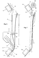
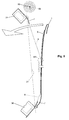
- Such a body part 1 is dash-dotted lines in Figures 1 and 2 and indicated in Figures 6, 7 and 8 in solid lines.
- both protective strips 8, 9 at the two lying in the narrow sides of the blank ends over the useful length L of the blank survive each case and form supernatants 10 and 11, where the film composite can be held by vacuum-loadable suction pads 30 and 31, without covering the area of the paint film blank 6 itself.
- the measured in the longitudinal direction of the blank 6 length of the end-side projection 11 is formed approximately to the measured in the longitudinal direction of the paint film blank 6 Aufsetzumble b 2 of the associated end-side suction pad 31.
- the length of the other, start-side projection 10 is also formed approximately on the Aufsetzbreite b 1 of the associated start-side suction pad 30.
- the start-side projection 10 is at least with respect to the lower-side protective strip 9 by a certain gripping length 1 over said Aufsetzbreite b. 1 extended so that even a withdrawal flag 12 is formed with this gripping length 1.
- the paint film blank 6 containing film composite 5 is presented in a defined position with the outside protective strip 8 freely accessible in the working area of a provided with an application tool 20, freely programmable industrial robot for recording by the application tool.
- This position-defined presentation of the film composite for the takeover by the handling robot can take place in different ways and also in different positions. It is important that on the one hand by mechanical stops or the like. exactly defined position of the film composite to be adopted does not change when accepting, ie it must be presented on a solid surface. On the other hand, the film composite must not rest on a rigid base.
- Two suction grippers 30, 31 are provided on the working side 22 of the application tool 20, and their suction-active receiving surfaces 32 lie in a uniform receiving plane 21. They correspond to the location and size of the mentioned supernatants 10 and 11 of the film composite 5. According to the start side and the end supernatant, the suction pads "start-side suction pads” 30 and “end-side suction pad” 31 are called. Both suction grippers can be placed with their suction-effective receiving surfaces on the top protection strip 8 in the region of the two supernatants 10, 11 and then applied with vacuum, whereby the recorded film composite is taken from the presented position in the application tool.
- both suction grippers 30, 31 are swiveled out of the receiving plane 21 at a certain angle ⁇ , ⁇ 'following the takeover of the film composite 5.
- the projections 10, 11 of the recorded and held-stretched composite film 5 then protrude obliquely and approximately mirror images of each other from the receiving plane 21 towards the back 23 of the application tool down, as indicated by dash-dotted lines in the figures. Due to suitable constructive provisions of the suction pads 30 and 31 and their pivot bearing but it must be ensured that the tension in the recorded film composite by the pivoting movement at best is changed in a negligible way. This will be explained in more detail below in connection with the description of the individual alternatives of the application tool 20, 20 'and 20 ".
- the size of the swivel angle ⁇ , ⁇ ' of the suction grippers 30, 31 is greater than the largest angle ⁇ occurring between the film composite 5 during the application process on the one hand and the connecting line between the two boundary edges 33, 33 'of the opposite suction grippers on the other hand (see FIG Suction gripper arrives, it can be recommended in this context, a swivel angle in the range of 10 to 60 °, preferably 15 to 45 °.
- the lower-side protective strip 9 is peeled off the paint film blank, for which purpose the take-off lug 12 is initially used on the starting projection 10.
- This withdrawal flag is detected by a gripping tool 50 which is movable within the application tool, and the protective strip 9 on the underside is pulled off the film composite, wherein in the embodiment shown in FIGS. 1, 2, 6 and 16a the starting side projection 10 is started and progressively the entire adhesive side of the paint film blank 6 is exposed.
- the underside protective strip is at least partially withdrawn from the stretched out in the application tool 20 film composite 5, this is aligned with the paint film blank 6 at a short distance to the adhering and position-defined and relentless detained body part 1 in the correct position. Subsequently, the paint film blank 6 is doctored by a longitudinally movable and flexible within the application tool 20 squeegee 90, 91 from the stretched-out spacer layer on the body part 1 to be bonded. Finally, the upper-side protective strip 8 is withdrawn from the outside of the completely applied paint film blank 6 due to a withdrawal movement of the application tool 20, in particular of the end-side suction gripper 31.
- the application tool 20 is pivoted away from the bodywork surface 1 by a virtual pivot axis lying in the vicinity of the start-side suction gripper 30, as indicated in FIG. 8 by the arrow shown in full lines.
- the application tool 20 can be moved in the direction of the start-side end of the paint film blank 6. Because of one and / or the In other of these movements of the application tool, the end-side suction gripper 31 pulls the outer protective strip 8 away from the paint film blank 6 applied completely to the body part 1.
- the protective strip 9 is withdrawn by the winding process - considered in itself - with a speed corresponding to the peripheral speed of the roll, which must be adjusted so that it coincides with the speed of the squeegee 90, 91. translational speed and winding speed are superimposed.
- the end-side suction gripper 31 is brought closer to the body surface 1 to be covered (see FIG. 7).
- the end-side supernatant 11 of the film composite 5 detected by the end-side suction gripper 31 can be allowed to slide in this phase, which can be achieved by a targeted lowering of the vacuum in the end-side suction gripper 31 in the sense of a smaller holding force.
- the paint film blank 6 is alsgerakelt during the application process with a very high line pressure. That is, it should be in the range of 10 to 50 N / cm, preferably 20 to 30 N / cm.
- the paint film blank 6 is doctored with a doctor blade 91 of a hard felt of about 10 to 20 mm thickness.
- the doctor blade 91 is placed on the film composite and guided along the application tool under strong contact with the film composite, the application tool in Stuck longitudinally of the paint film blank stationary over the body part.
- the adhesive side of the paint film 6 is aufgerakelt with high line pressure on the body surface and thereby pushed out the smallest gas inclusions from the adhesive joint progressively.
- first adhesive adhered to the exposed adhesive layer air is squeezed out due to the high line pressure of the squeegee.
- the paint film not only very firmly adheres to the body surface, but it can not come to a subsequent collection of microfine gas inclusions to visible gas bubbles, because - as I said - no more gas inclusions remain in the glue joint.
- a peculiarity of the paint film application to vertical frame legs of car side doors is that after the proper sticking of the paint film blank on the flat side of the frame leg whose protruding lateral edges must be bent and pressed back. This may, as long as no robotic tool is provided yet, in a conventional manner manually u.U. be made with the help of special hand tools for pressing back.
- the outer protective strip 8 is provided with a moderately strongly adhesive pressure-sensitive adhesive layer, so that it leaves without much force and, above all, residue-free from the paint film 6 pullers.
- the lower protective strip 9 is provided with a non-stick coating, so that it can also be pulled off easily and without tearing or peeling in layers from the very strongly adhesive pressure-sensitive adhesive layer of the lacquer film 6. It is envisaged that the lower protective strip 9 will deflect at a narrow angle, i. due to a bending of the same by a tight bending radius already solved automatically from the adhesive side of the paint film blank 6. In any case, the lower protective strip 9 should be easier to detach from the adhesive side of the paint film or the support film, as the outer protective strip 8 can be detached from the outside of the paint film.
- the composite film 5 according to the exemplary embodiment was taken as the basis of FIGS. 1, 2, 6 and 16a.
- This film composite 5 has in common with the other exemplary embodiments of FIGS. 16b, 16c, 17a and 17b the feature that both start-side and end-side projections 10 and 11 (FIGS. 16a, 16b and 16c) and projections 10 'and 11' (FIGS and 17b) are provided, on which the film composite outside of the paint film blank 6 can be held.
- the support film 7 may be formed identical to the paint film 6. In any case, the support film should be separated from the usable part of the paint film blank 6 by an interruption 13, so that it is easily detached from the paint film 6.
- the embodiment of the film composite 15 of Figure 16b differs from that of Figure 16a only by the formation of the trigger tab 12 ', which is formed in a single layer in the film composite 15 and is an integral part of the lower protective strip 9.
- the Abzugsfahne 12 'within the stack of film composites easily hang down something.
- the associated withdrawal lug 12 ' protrudes into the region of the gripping tool of a gripping-dotted line indicated in FIG. 16b of an extraction device integrated in the application tool; the withdrawal flag 12 'can be reliably detected by this gripping tool despite a certain drooping.
- Both withdrawal tabs are part of the lower one
- This type of formation of the film composite 15 ' is provided for complete removal of the lower protective strip 9 from the film composite prior to the application of the paint film blank
- This complete stripping of the lower protective strip can be carried out within the application tool by the two withdrawal flags 12' and 12 "recorded in the application tool film assembly 15 'detected by moving, integrated in the application tool gripping tools and are moved transversely to the receiving plane of the held film composite away, as dash-dotted lines in Figure 16c is indicated.
- the withdrawn protective strip can be dropped by opening the gripping tools in a waste container.
- the advantage of the film composite 15 'or the previous complete removal of the lower protective strip 9 before applying the paint film is that the application tool can be made much simpler compared to one in which the lower protective strip is removed during the application process. Under cleanroom conditions, which today are often created in paint shops for automobiles, this way of working may well be justifiable.
- the further exemplary embodiment of a film composite 16 shown in FIG. 17a corresponds, apart from the two-ply, i. Supernatants 10 'and 11' formed without embedded support film, largely the film composite shown in FIG. 16b. Only in the area of the paint film blank 6 itself is the film composite 16 three-layered. The one side mounted exhaust tab 12 'is single-layered.
- This film composite 16 is particularly inexpensive because of the omission of the interposed support films, but can not pile up in a larger number until the area of the supernatants 10 'and 11' flat and flat. For small numbers of film composites 16 within a stack, however, it would still be possible to adopt a film composite in the application tool safely and accurately.
- this film composite is suitable for an application-simultaneous removal of the lower protective strip, as described above in connection with Figures 1 to 3 and 5 to 8 already has been.
- This film composite 16' is thus for a complete removal of the lower protective strip 9 from the film composite within the application tool prior to application the paint film blank suitable.
- This pivotal movement of the suction pads serves to secure a firm hold of the detected protrusions 10 and 11 of the film composite on the suction pads despite a V-shaped indentation of the expanded film composite from the receiving plane during the application process - see, for example, angle ⁇ in Figure 6.
- the pivoting of the suction pads is structurally designed such that the tension in the recorded film composite by a pivoting movement of the suction pads 30, 31 is changed at most in a negligible manner. That is, the mutually facing boundary edges 33 and 33 'of the absorbent receiving surfaces 32 must not have any other mutual distance after pivoting of the suction pads as before pivoting.
- the various embodiments of the application tools differ from each other, but what will be discussed in more detail below.
- the stops 38 or 38 ' determine the receiving position shown in solid lines and the stops 39 or 39' the working position indicated by the dot-dash line the suction pads 30 and 31.
- the for the receiving position the suction pads 30 'and 31' relevant stops are designated at application tools 20 'of Figure 4 with 43 and 43', whereas the responsible for the working position stops with the reference numerals 44 and 44 'are provided.
- This gripping tool is movably mounted and provided with a corresponding movement drive such that it can be moved close to the receiving plane 21 next to the start suction gripper - starting position, on the other hand, the gripping tool can be moved from this starting position below the receiving plane 21 into a working plane 53
- the details of the gripping tool itself will be discussed below in connection with the individual related embodiments, and it should be noted at this point only that in all A shown, the gripping tool is moved parallel to and parallel to itself exemplary embodiments, the gripper tools are rotatably mounted and coupled to a corresponding rotary drive and serve as a winding core for the end detected lower protective strip 9.
- the gripping tool is rotatably mounted in a laterally offset next to the suction pads 30 and 31 arranged angular gear 54 from which it protrudes axially freely.
- the gripping tool can be selectively set for winding on the drive motor 55 in rotation.
- the structural design of the movable guide of the gripping tool is shown consistently in the various embodiments of application tools; it is best seen in Figure 5.
- the gripping tool is designed as a rotatably mounted beaking pliers 50, with the end of the seized guard strip 9 can also be wound up at the same time.
- angle gear 54 and motor 55 drive block of the gripping tool is coupled by parallelogram 56 to a carriage 59 so that the drive block or the beaking pliers are translationally moved on a circular arc from the starting position shown in Figure 5 in full lines in the dash-dotted line indicated working position can.
- the starting position - it is determined by the attached to the carriage 59 stop 58 - is the beak pliers with its center at the level of the receiving plane 21 of the application tool.
- the beak tongs is after transfer to their working position in the working plane 53 below the receiving plane.
- the working position is determined by the likewise attached to the carriage 59 stop 58 '.
- a displacement drive 57 is provided in the form of a working cylinder, which connects in the illustrated embodiment, two diagonally opposite hinge points of the four-bar linkage, which is spanned by the two parallelogram links 56 and their joints .
- the carriage 59 is guided on guide rods 60 movable parallel to the receiving plane 21.
- the carriage or the pliers can be moved parallel to the working plane 21.
- the displacement of the carriage 59 corresponds at least to the length L of the paint film blank 6 to be applied.
- the beaking pliers lie in the same region in which the already mentioned suction pads 30, 31 and They are absorbed by them composite film. In the same area is also described below, also carried by the carriage 59 squeegee 90, with which the paint film is doctored onto the body.
- the drive block 54/55 for rotating the gripping tool must therefore lie in a plane beyond gripping tool, suction gripper, film composite and doctor blade.
- the movably mounted gripping tool - as mentioned - at the same time designed as a winding device, so that it can be held together with the Rackel 90/91 on the carriage 59 and moved with it, but nevertheless allowed, the lower protective strip application of simultaneous remove the paint film.
- the doctor blade with its working edge can be shifted from a waiting position shown in solid lines in FIG. 5 into a working position which is close to the receiving plane 21 and indicated in the working position with a certain force against the holding position
- the carriage-like doctor blade holder 90 - as can best be seen in FIG. 5 - is mounted on a carriage guide 93 which is inclined to the receiving plane 21 and provided with a corresponding actuating drive 92 in the form of a working cylinder hen, which also applies the contact pressure of the squeegee.
- the doctor can be moved in the working position in a straight line and parallel to the receiving plane 21.
- the carriage guide 93 in turn is arranged on the aforementioned slide 59, which indirectly also carries the pivotally supported drive block 54/55 for the beak tongs.
- the displacement drive 61 of the carriage or the blade 91 can be moved parallel to the working plane 21, wherein the paint film 6 is aufgerakelt on the body part 1 with a certain line pressure.
- the lacquer film must first be applied with very high line pressure, but on the other hand the body surface is slightly curved. Nevertheless, in order to be able to realize as uniformly high line pressure as possible over the entire width of the doctor blade and still leave no pressure marks on the lacquer film to be applied, the doctor blade 91 consists of a hard felt.
- the automation-compatible stacking device The automation-compatible stacking device
- a horizontal stacking platform 96 elastically mounted on a base frame 100 is arranged with lateral holding and guiding webs 97, 98, on which the foil composites are stacked to form a stack 95 and so on Application tool 20 can be presented horizontally lying.
- the lateral holding and guiding webs 97, 98 the foil composites contained in the stack are precisely aligned one above the other.
- the stacking platform need not be aligned exactly horizontal, although this arrangement is preferred. In some cases, a slight skew of the stack may make sense.
- the lower side elastically supported stacking platform is guided by lateral guide pins in vertical slots in the guide webs 98, so that the stacking platform not only vertically displaceable while maintaining its defined position with respect to the horizontal coordinates, but also limited by a certain guide pin 99 longitudinal axis is tiltable.
- This tiltability is made possible by the elastic intermediate links 104 between the support columns 101 and the underside of the stacking platform.
- the elastic intermediate members also allow limited axial tilting of the stacking platform about a perpendicular to the plane of pivot axis.
- the guide columns 101 in vertical guides 102 are movable and tensioned by springs 103 in a limited by stops (adjusting nuts 105), upper end position.
- the stacking platform can yield in a translational manner in the vertical direction.
- This in many respects elastic, albeit limited flexibility of the stacking platform is important for a gentle recording of the presented on the stacking platform film composite by the robot-guided application tool. Any lying within the movement tolerance of the industrial robot position deviations between the presented for takeover film composite on the one hand and the transfer position of the application tool on the other hand can cause no damage or bruises on the film composite due to this flexibility, because the stacking platform can adapt to a slight positional deviation of the application tool automatically and informally.
- the stacking platform 96 is held vertically adjustable in the manner and provided with a controllable height adjustment, that the upper edge of the stack 95 is always in a constant height position, regardless of the number of stacked foil composites.
- the controlled height adjustment of the stacking platform is achieved in the embodiment shown in Figure 3 by the following structural components.
- the upper edge of the stack is detected by a height-adjustable light barrier 109, which has two slightly vertically offset light beams with separate detectors.
- the lower light beam should be darkened by the stack, whereas the upper light beam must not be darkened. If the lower light beam is not darkened, the stack is raised slowly until the lower light beam is darkened again by the stack. If, on the other hand, both photocells are darkened, the stack is slowly lowered, until such time as - until - the upper light beam is released from the stack again.
- the signal of the light barrier is indirectly forwarded via a suitable control unit 110 to an electric adjusting motor 107, which raises or lowers the stacking platform as needed.
- the support columns guided against rotation in the vertical guides 102 are provided on the underside with adjustment spindles 106. These are acting as stroke limiting stops adjusting nuts 105 screwed, the underside hit the front of the vertical guides 102 and determine the altitude of the support columns 101.
- the support columns are biased by the lifting springs 103 constantly upwards and keep the adjusting nuts to stop.
- the adjusting nuts in turn can be rotated by the adjusting motor 107 via toothed belt 108 and depending on the direction of rotation of the adjusting the stack platform can be raised or lowered.
- Such or a similar elastically limited resilient stacking platform is also associated with the other application tools.
- the beak tongs 50 picks up the starting lug 12 of the recorded film composite.
- the beaking pliers from the starting position in the working position or in the working plane 53 is transferred, at the same time the winding drive 55 is turned on.
- the winding speed is in this phase on the displacement speed the beak tongs on the initial circular arc in such a way coordinated that drawn off from the film composite part of the lower protective strip 9 on the one hand wound with a certain density on the beak tongs and on the other hand a certain initial distance of the adhesive side of the paint film blank is exposed.
- the position of the drive block 54/55 at the end of this preparation phase of the application process is shown in phantom in FIG. 5 (left-hand position). At least the last operations of this preparation phase preferably already take place in such a position of the application tool, in which the film composite is aligned in the correct position at a small distance in front of the body part.
- the actual application phase of the paint film blank begins.
- the doctor 90/91 is lowered from the standby position shown in solid lines on the receiving plane in the film composite 5 in the direction of the arrow, wherein the recorded in the blade holder 90 doctor blade 91 felt with an edge in the film interruption 13 before the paint film blank 6 touches - see Figure 6, below.
- the illustration in Figures 6 to 8 is accordingly selected in vertical position. Due to the contact pressure exerted on the doctor blade, the film composite is pressed onto the surface of the adjacent body part 1 to be applied, the film composite being pushed out of the initially stretched release position in a V shape.
- the shorter leg of the V-shaped strained composite film initially assumes a maximum angle ⁇ with respect to the receiving plane 21, which must be smaller than the pivoting angle ⁇ of the start-suction pad 30, so that the film composite can not be detached from the suction-effective contact surface of this suction pad.
- the doctor blade 91 shown in FIG. 6 Starting from the starting position of the doctor blade 91 shown in FIG. 6, the latter is now guided along the application film under strong contact pressure with the film composite, wherein the application tool remains stationary over the body part in the longitudinal direction of the paint film blank.
- the windingly driven beak tongs 50 are preceded in advance by the same speed as the doctor blade and at a constant distance A from the doctor blade.
- the beaking pliers are driven at such a winding speed that the lower protective strip 9 detached from the paint film at the advancing detachment point 69 is wound continuously and tightly into a winding 68.
- the circumferential speed of the roll is constant, namely equal to the translation speed of the doctor, whereas the rotational speed of the beak tongs 50 decreases with increasing winding diameter.
- the film composite 5 is supported by the winding becoming larger.
- the end of the doctoring process is shown in FIG.
- the squeegee 91 has reached the end of the paint film blank 6 and the now very large winding 68 of the lower protective strip is already outside of the body part.
- the end-side suction gripper 31 has been approached towards the end of the doctoring process to the body part to the spreading angle ⁇ 'of the film composite against the receiving plane 21 is not too large, at least not greater than the pivot angle ⁇ ' of the end suction pad 31, so a firm grip the end-side supernatant 11 is ensured on the suction pad.
- the vacuum is lowered in the interior of the end-side suction pad 31 in the sense of a lower holding force to allow slipping of the film composite without too strong increase in tensile stress. It is all the more important that the holding force defined and reduced by the level of the vacuum does not collapse uncontrollably.
- the paint film 6 is already completely adhered to the body part 1 and the lower protective strip completely withdrawn from the film composite and wound into a winding 68. It only needs the outer protective strip 8 to be deducted from the outside of the applied paint film 6, which is still held at both ends by means of the two suction pads 30 and 31 in the application tool. This removal is done by a large-scale pivoting movement of the application tool away from the body part, wherein the release point 69 'of the outer protective strip against the Aufrakelides runs from the end of the paint film to the beginning. In Figure 8, the removal of the outer protective strip is carried out by a long-range movement of the end suction pad. However, it is also conceivable that the outer protective strip is made due to a sweeping movement of the start-side suction pads.
- both protective strips can be dropped over a waste container.
- the held by the suction pads outer protective strip is dropped by switching off the vacuum and venting the suction pads, which can be done in virtually any position of the application tool.
- the application tool to throw off the wound on the beak tongs lower protective strip, the application tool must be placed in such a position that the beak tongs is aligned approximately parallel to the direction of gravity and with its free end facing down, so that after opening the beak tongs the loosened winding 68 can fall axially from the winding core due to gravity.
- the pivot pins 34 of the two suction grippers 30, 31 are arranged concentrically to the boundary edge 33, 33 'of the suction gripper facing the paint film blank 6, i. the geometric ⁇ rter the pivot axes are in the receiving plane 21 of the application tool.
- the two suction pads thus pivot in this embodiment around the boundary edges 33 and 33 ', with the result that the tension in the recorded composite film 5 is not changed by a pivoting movement.
- the advantage of this solution is the structural simplicity; However, it has the disadvantage that the bearing 35 of the pivot pin, and even the pivot pin 34 themselves project beyond the receiving plane 21 or working side 22 of the application tool down what u.U. can be annoying for receiving a thin film composite of a flat surface.
- the pivot bearing with the bearing pin 34 and the journal bearing 35 of the illustrated on the left, start-side suction pad 30 ' is formed as a conventional journal bearing whose center is offset relative to the receiving plane 21 of the application tool 20' in the direction of the back 23 to such an extent that even the lying on the receiving plane 21 closest outlines of the journal bearing 35 'still offset relative to the receiving plane 21 of the application tool 20' in the direction of the rear side 23.
- the journal bearing 35 'of the start-side suction pad 30' is also fixed immovably on the application tool, as the associated separate pivot drive 40 in the form of an acting on the pivot lever 36 working cylinder.
- a tension spring 42 biased by a tension spring 42 toward an occupied during recording a composite film end position, which is predetermined in the illustrated embodiment by a settable on the slide guide stop ring 41 '.
- a tension spring can also be used, with which an adjustable and independent of the displacement tension force can be exerted on the film composite.
- the end- side suction gripper 31 ' is pivoted by an approximately equal angle, but in the opposite direction of pivoting, so that the left boundary edge of its contact surface 32 - based on the sliding system of the holder of the end suction pad 31' - by about the same stroke h to the right, so in the opposite direction as the other suction pad 30 'is moved.
- there is no increase in the tensile stress in the recorded film composite because the movably supported, end suction pad 31 'the left-directed, from the start side suction pad 30' exercised train in the film composite without coercion, but contrary to the action of the tension spring 42 is able to follow while doing twice the offset measure, namely the distance 2 h covers. It is important here that the start-side suction gripper 30 'is held unyielding in the application tool and can not shift within the application tool due to any force acting in the direction of pull of the film composite during the doctoring process.
- FIG. 9 shows a further exemplary embodiment of an application tool 20 ", which avoids a complex carriage construction."
- the pivot bearing 34 ", 35" of the start-side suction pad 30 "shown on the left in Figure 9 is likewise conventional, similar to the application tool according to Figure 4 Pivot bearing formed whose center is offset relative to the receiving plane 21 of the application tool 20 "in the direction of the rear side 23 by a certain extent, so that the recording plane 21 nearest outlines of the journal bearing 35" still an upward distance to the receiving plane 21 of Application tool 20 "have.
- pivotally mounted end suction pad 31 is also movable in the longitudinal direction relative to the application tool 20", but not by means of a slide guide.
- the pivoting of the end-side suction gripper with the longitudinal movement structurally combined, which is realized in the illustrated embodiment by a four-bar linkage. This is formed by two rockers 45 and 45 ', which are hinged on the one hand to the end-side suction gripper 31 "on the one hand, and to the application tool 20" on the other hand.
- the position of the pivot points including the length of the rockers 45 and 45 ' is selected on the one hand, that the instantaneous 46, 46' in all positions of the suction pad 31 "relative to the receiving plane 21 of the application tool 20" is offset downwards, ie in the opposite Direction relative to the receiving plane is like the journal bearing 34 ", 35" of the start-side suction pad 30 ".
- the advantage of the pivot bearing of Figure 9 combines the advantages of a simple structural design with the other advantages of the embodiment of Figure 4.
- a conversion of the application tool 20 "to another length of the film composite is also possible here, provided the frame, which the upper pivot bearing of Swing 45 and 45 'and the stops 47' and 48 'carries, in the longitudinal direction of the application tool at different positions can be screwed.
- the gripping tool is in each case designed as a movably guided and rotatable beaking pliers 50 and 50 ', each having an upper (51 or 51') and a lower beak part 52 and 52 ', which are formed over their longitudinal extent, each of constant cross-section.
- the upper beak part 51 or 51 ' is channel-shaped in cross-section, with the two side edges forming a contact plane 51 "of the upper beak part together, the lower beak part dipping radially between these side edges when closing the beak tongs.
- the upper beak part 51 or 51 ' can be designed immovably in the sense of an opening and closing movement of the beak tongs 50, 50'.
- the lower beak part 52, 52 ' must be movably arranged and guided in this sense and be equipped with a corresponding movement drive.
- the difference between the two beak pliers consists essentially on the one hand in the way they are attached to the trigger lug 12 of the recorded film composite and how they then release the generated winding 68 again and on the other in the nature of the opening and closing movement of the beak pliers.
- beak tongs must by a suitable control in the rotary drive 55 of the beak tongs automatically the o.g. Starting position of the beak pliers are swung.
- the lower beak portion 52 in the sense of an opening and closing movement of the beak 50 by 90 ° pivoted, so that in the receptive starting position - beak 50 completely open - the lower beak portion 52 at right angles protrudes downwards to the receiving plane 21 of the application tool 20.
- the lower beak part is connected to the upper beak part 51 via a pivot bearing 62, which is tangential with its pivot axis aligned with the circumference of the beak tongs and arranged close to the periphery.
- the lower beak portion 52 can be pivoted, on the one hand, into the closed position shown in full lines and, on the other hand, into the open position indicated by dash-dotted lines, in which the lower beak portion protrudes downward at right angles from the axis of rotation of the beak tongs.
- the actuating cylinder is provided at its exposed end with a - not shown in Figure 10 - pressure supply head, which allows a pressure supply from a fixed circumferential point to the rotating actuating cylinder.
- the advantage of the beak tongs 50 according to FIG. 10 is that they are structurally relatively simple and robust, not only themselves but also their actuating drive.
- a disadvantage of this embodiment is that when receiving a composite film, ie down in the open state of the beak tongs, the lower beak part far below the receiving plane 21.
- the receiving platform must therefore have a recess at the location of the open projecting lower beak portion or be formed correspondingly narrow at least at this point.
- the beaking pliers as a whole out of the range of the film composite 5 to be absorbed can be moved out or retracted transversely to the longitudinal direction, the executable travel (transverse stroke Hq) of the beaking pliers corresponding at least to the width of the film composite 5 to be picked up or the withdrawal tab 12.
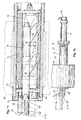
- the beak tongs 50 ' is used in addition to the gripping function with respect to the withdrawal lug 12 of the film composite - as I said - as a winding core for the lower protective strip 9 and is accordingly rotationally driven.
- the beak tongs on the freely accessible front end of a quill 71 is supported, which in turn due to a non-circular outer contour against rotation but axially movable in a rotatably mounted in the angular gear 54 'and rotatably driven hollow shaft 70 is mounted.
- the Axialverschieben the beak tongs to the transverse stroke H q is only in the open state and when closing only in such a rotational position of the beak tongs, that the upper and lower beak member are positioned above or below the male film composite or projecting therefrom Abzugsfahne 12. Only at the outer end of the transverse stroke H q , ie when the beak tongs is pushed over the entire width of the composite film, the beak tongs is closed; This state is shown in Figure 11 in solid lines and indicated by dash-dotted lines in Figure 12.
- an actuating cylinder 77 is mounted at the axially opposite end of the quill, which rotates with the quill and which accordingly must be provided with a stationary in the direction of rotation pressure supply head 78 for pressure supply with respect to both operating directions of the rotating actuating cylinder, as indicated in the figure on the far right.
- the closing and opening movement of the beaking pliers is coupled to the displacement drive for them in such a way that the movement for closing and opening the beaking pliers is derived from the axial movement of the quill.
- the lower beak portion 52 ' is mounted on a guide rod 72 which is movably guided within the hollow sleeve 71 by means of a pair of parallelogram links 73 on a circular arc, wherein the guide rod not only a radial stroke in the sense of opening or closing the Beak tongs perform, but also a short axial stroke h a of the guide rod and the lower beak portion 52 'relative to the rigidly connected to the quill upper beak portion 51'.
- the guide rod is tensioned by a mounted at its rear end opening spring 76 in the direction of the open position of the beak tongs.
- a transverse pin 74 guided radially movably in the front region of the guide rod is arranged, which projects through axially aligned slots in the sleeve to the soffit of the non-circular inner bore of the hollow shaft 70.
- the end face of the hollow shaft is at the edge by a stop ring 75 closed, which protrudes with axially projecting webs 75 'in recesses on the quill and can cooperate with the cross pin.
- the beaking pliers 50 'according to FIGS. 11 and 12 have the advantage over the beaking pliers according to FIG. 10 that they can readily be withdrawn completely behind the receiving plane 21 in the receptive state, so that a film composite can also be moved by a larger flat table surface through the associated flat table surface Application tool could be included.
- a disadvantage is the somewhat more complicated drive because the beaking pliers, in addition to a radial opening and closing movement, also have to carry out a relatively large transverse stroke H q for the lateral attachment of the opened beaking pliers to the withdrawal lug of the film composite received by the application tool.
- FIG. 13 shows the overview drawing with respect to the two exemplary embodiments of suction strips 80 and 80 'shown in detail in FIGS. 14a, 14b and 15a, 15b.
- the gripping tool movable within the associated application tool likewise serves as a winding core for the Accordingly, it is rotatably drivable via the bevel gear 54 "and the drive motor 55 and has an approximately semicircular or D-shaped cross section
- the suction strip which can be acted upon or vacuumed by a vacuum, has an absorbent contact surface 88, 88 'on its flat side
- the interior of the squeegee-bearing output shaft of the bevel gear 54 is hollow drilled axially, this hole serves as a vacuum supply.
- a non-co-rotating pressure supply head is mounted at the rear end of the projecting from the angular gear output shaft.
- the serving as a winding core squeegee in the receptive state must be specifically retracted in such a rotational position that the cross-sectionally D-shaped suction with its flat receiving surface is parallel to the receiving plane of the application tool or parallel to the withdrawal flag of the recorded composite film.
- the withdrawal tab 12 on the start-side projection of the film composite to be taken or already recorded in the application tool only the interior of the suction strip applied to the withdrawal tab needs to be subjected to a vacuum.
- the suction strips 80 and 80 'shown in FIGS. 14a, 14b and 15a, 15b differ essentially in their structural design of the absorbent surface 88 or 88' that can be applied to the film composite 5.
- a knobbed sheet 81 is crimped airtight in the open side of a substantially semicircular tube.
- the nubble plate is provided with a plurality of rastered arranged, for example, cylindrical support nubs 82, between which transfer openings 83 are mounted for the vacuum.
- the support knobs form a very small contact and support surface for the recorded film composite 5, so that act over almost the entire, lying between the lateral attachment flanging surface of the dimpled sheet, the upcoming vacuum on the film composite and hold the film composite.
- the interior of the squeegee can be acted upon or ventilated by a suction port 84 which passes through the drive shaft of the gripping tool serving as a winding core.
- the squeegee 80 'shown in FIGS. 15a, 15b is also based on a substantially semicircular tube, in the open side of which a lattice of lamellas having, for example, a longitudinal ridge 86 and a multiplicity of short transverse ridges 85 recessed into niches 87 is formed.
- the caulked with the transverse webs longitudinal sides of the half-tube are ground flush in the region of the contact surface 88 'with the lattice fins.
- the vacuum can be fed to the squeegee via a suction port 84 'which is likewise arranged in the shaft carrying the rotating gripping tool.
- 15a, 15b in relation to the squeegee 80 is a larger crossover cross section from the interior of the squeegee into the absorbent surface itself.
- the crossover cross section on the one hand and the absorbent surface on the other hand are of equal size, whereas in the case of the squeegee 80 (FIGS. 14a, 14b) there is a great difference in this respect.
Landscapes
- Engineering & Computer Science (AREA)
- Manufacturing & Machinery (AREA)
- Automobile Manufacture Line, Endless Track Vehicle, Trailer (AREA)
- Lining Or Joining Of Plastics Or The Like (AREA)
Abstract
Claims (37)
- Procédé pour l'application automatisée d'un film autoadhésif sur des pièces de carrosserie, dans lequel un flan de film est saisi et est maintenu tendu, du côté extérieur non adhésif, par deux extrémités opposées, au moyen de dispositifs de préhension aspirants pouvant être sollicités par le vide, le flan de film maintenu tendu étant orienté en position exacte par-dessus la pièce de carrosserie à revêtir par collage et étant collé sur celle-ci,
caractérisé en ce que
des flans de film de peinture allongés préconfectionnés (6) pour l'application d'un film de peinture, sont préparés dans une réalisation selon les caractéristiques a) à c) et en ce que pour l'application automatisée des flans de film (6) ainsi préparés, on procède conformément aux caractéristiques d) à g) :a) chaque flan de film de peinture allongé préconfectionné (6) est contenu dans un composite de film (5, 15, 15', 16, 16') et est pourvu, du côté extérieur et inférieur, d'une bande protectrice (8, 9) adhérente mais facilement décollable, les deux bandes protectrices (8, 9) dépassant à chaque fois (dépassements 10, 10', 11, 11') au niveau des deux extrémités situées dans la région des petits côtés du flan de film de peinture (6) par rapport à la longueur utile (L) du flan de film de peinture (6),b) la longueur mesurée dans la direction longitudinale du flan de film (6), d'un des dépassements (11, 11') ci-après désigné "dépassement du côté du bout", est réalisée approximativement de manière correspondant à la largeur d'application (b2) du dispositif de préhension aspirant associé (31), mesurée dans la direction longitudinale du flan de film de peinture (6), tandis que la longueur de l'autre dépassement (10, 10'), ci-après désigné "dépassement du côté du début" est certes aussi réalisée approximativement de manière correspondant à la largeur d'application (b1) du dispositif de préhension apsirant associé (30), mais au niveau du dépassement du côté du début (10, 10') au moins la bande protectrice (9) du côté inférieur est prolongée d'une longueur de préhension définie (1) au-delà de ladite largeur d'application (b1) (languette de traction 12, 12'),c) le composite de film (5, 15, 15', 16, 16') ainsi réalisé et contenant le flan de film de peinture (6) se présente, dans une position définie de la bande protectrice (8) du côté extérieur, de manière librement accessible dans la zone de travail d'un robot industriel librement programmable pourvu d'un outil d'application (20, 20', 20") de manière à être reçu par l'outil d'application (20, 20', 20"),d) le composite de film (5, 15, 15', 16, 16') est reçu par deux dispositifs de préhension aspirants (30, 30', 30", 31, 31', 31") prévus sur l'outil d'application (20, 20', 20"), reposant avec leurs surfaces de réception aspirantes (32) dans un plan de réception unitaire (21), au niveau de la bande protectrice (8) du côté supérieur, dans la région des deux dépassements (10, 10', 11, 11'), les deux dispositifs de préhension aspirants (30, 30', 30", 31, 31', 31") étant ensuite pivotés hors du plan de réception (21) suivant un angle respectif déterminé (α, α'), de telle sorte que les dépassements reçus (10, 10', 11, 11') du composite de film maintenu tendu (5, 15, 15', 16, 16') dépassent obliquement et approximativement symétriquement l'un par rapport à l'autre depuis le plan de réception (21) dans la direction du côté arrière (23) de l'outil d'application (20, 20', 20"),e) la bande protectrice (9) du côté inférieur est retirée, en commençant par l'extrémité du côté du début du flan de film de peinture (6), guidée par le dépassement (10, 10') du côté du début, servant de languette de traction (12, 12') et saisi par un outil de préhension (50, 50', 80, 80') déplaçable à l'intérieur de l'outil d'application (20, 20', 20"), et ainsi le côté adhésif du flan de film de peinture (6) est exposé,f) après l'orientation correcte du composite de film (5, 15, 15', 16, 16') maintenu tendu par l'outil d'application (20, 20', 20") à faible distance de la partie de la carrosserie (1) à coller et fixée de manière définie et inflexible, le flan de film de peinture (6) est appliqué par raclage, par une racle (90, 91) flexible et déplaçable longitudinalement le long de l'outil d'application (20, 20', 20") depuis la position tendue à distance sur la partie de la carrosserie (1) à coller,g) ensuite la bande protectrice (8) du côté supérieur est retirée depuis le côté extérieur du flan de film de peinture (6) appliqué, par le biais d'un mouvement de traction de l'outil d'application (20, 20', 20"), notamment du dispositif de préhension aspirant du côté du bout (31, 31', 31"). - Procédé selon la revendication 1,
caractérisé en ce que
le mouvement de pivotement des deux dispositifs de préhension aspirants (30, 30', 30", 31, 31', 31") s'effectue de telle manière que la tension de traction dans le composite de film reçu (5, 15, 15', 16, 16') est modifiée tout au plus de manière négligeable par le mouvement de pivotement. - Procédé selon la revendication 1,
caractérisé en ce que
la valeur de l'angle de pivotement (α, α') des dispositifs de préhension aspirants (30, 30', 30", 31, 31', 31") est supérieure à l'angle maximal (β) produit pendant l'opération d'application entre le composite de film (5, 15, 15', 16, 16') d'une part et la ligne de connexion entre les deux arêtes de limitation (33, 33') situées dans le plan de réception (21) des dispositifs de préhension aspirants opposés (30, 30', 30", 31, 31', 31"), d'autre part. - Procédé selon la revendication 1,
caractérisé en ce que
dans la région des dépassements (10, 11) entre les deux bandes protectrices (8, 9), à chaque fois un film de support (7) correspondant à l'épaisseur du film de peinture (6) est inséré, de sorte que le composite de film (5, 15, 15') - à part certaines interruptions - soit réalisé avec trois couches sur toute sa longueur et présente une épaisseur uniforme (D), et en ce que les composites de film (5, 15, 15') sont offerts sous forme empilée. - Procédé selon la revendication 4,
caractérisé en ce que
les composites de film (5, 15, 15') sont offerts sous forme empilée au moins en position approximativement horizontale. - Procédé selon la revendication 1,
caractérisé en ce que,
au début de l'opération d'application, la bande protectrice inférieure (9) n'est que partiellement retirée et le côté adhésif du flan de film de peinture (6) est d'abord seulement partiellement exposé et en ce que la poursuite du retrait de la bande protectrice inférieure (9) ou l'exposition du côté adhésif du flan de film de peinture (6) s'effectue en fonction de l'avance de l'application par raclage du flan de film de peinture (6) sur la pièce de carrosserie (1). - Procédé selon la revendication 1,
caractérisé en ce que
le flan de film de peinture (6) n'est appliqué par raclage sur la pièce de carrosserie (1) que dans une direction unique et avec seulement une racle (90, 91). - Procédé selon la revendication 1,
caractérisé en ce que
pendant l'application par raclage, une distance (A) approximativement constante est conservée entre la racle avançant (90, 91) d'une part et le point de traction également avançant de la bande protectrice inférieure (9) à retirer. - Procédé selon la revendication 1,
caractérisé en ce que
le retrait de la bande protectrice inférieure (9) s'effectue par superposition d'une part d'un mouvement de translation d'un dispositif d'enroulement enroulant la bande protectrice inférieure (9), lequel est déplacé avec une vitesse coïncidant avec la vitesse de la racle, et d'autre part un mouvement d'enroulement du dispositif d'enroulement, le dispositif d'enroulement - considéré en soi - enroulant la bande protectrice retirée (9) également avec une vitesse coïncidant avec la vitesse de la racle (90, 91). - Procédé selon la revendication 1,
caractérisé en ce que
vers la fin de l'opération d'application par raclage, le dispositif de préhension aspirant du côté du bout (31, 31', 31") est rapproché de la surface de la carrosserie (1) à revêtir par collage. - Procédé selon la revendication 1,
caractérisé en ce que
le dépassement du côté du bout (11, 11') du composite de film (5, 15, 15', 16, 16'), saisi par le dispositif de préhension aspirant du côté du bout (31, 31', 31"), continue de glisser vers la fin de l'opération d'application par raclage. - Procédé selon la revendication 1,
caractérisé en ce que
l'on effectue l'application par raclage avec une pression linéaire de l'ordre de 10 à 50 N/cm, de préférence de 20 à 30 N/cm. - Procédé selon la revendication 1,
caractérisé en ce que
le flan de film de peinture (6) est appliqué par raclage avec une racle (91) constituée d'un feutre dur ayant une épaisseur d'environ 10 à 20 mm. - Procédé selon la revendication 1,
caractérisé en ce que
pour le retrait de la bande protectrice extérieure (8) du flan de film de peinture appliqué complètement (6), l'outil d'application (20, 20', 20") est écarté de la surface de la carrosserie (1) par pivotement autour d'un axe de pivotement virtuel situé à proximité d'un des dispositifs de préhension aspirants (30, 30', 30", 31, 31', 31"), de préférence à proximité du dispositif de préhension aspirant du côté du début (30, 30', 30"), et/ou est déplacé dans la direction de l'extrémité opposée du flan de film de peinture (6), de telle sorte que le dispositif de préhension aspirant écarté (31, 31', 31") retire la bande protectrice extérieure (8) du flan de film de peinture appliqué (6). - Dispositif pour l'application automatisée d'un film autoadhésif sur des pièces de carrosserie, constitué d'un outil d'application pouvant être manipulé par un robot industriel librement programmable, qui présente, d'un côté plat de l'outil d'application, appelé ci-dessous "côté de travail", deux dispositifs de préhension aspirants disposés à distance l'un de l'autre, pouvant être ventilés ou sollicités par du vide de manière ciblée, qui permettent de saisir au niveau de deux extrémités opposées et de maintenir tendu un flan de film du côté extérieur non adhésif, de telle sorte que le flan de film puisse être manipulé librement dans l'état tendu par le robot industriel, notamment pour mettre en oeuvre le procédé selon la revendication 1,
caractérisé en ce que
pour l'application de flans de film de peinture allongés préconfectionnés (6), contenus à chaque fois dans un composite de film (5, 15, 15', 16, 16') réalisé de manière automatisée et préparé individuellement, l'outil d'application (20, 20', 20") présente les caractéristiques suivantes :a) les deux dispositifs de préhension aspirants (30, 30', 30", 31, 31', 31") sont à chaque fois disposés de manière pivotante dans l'outil d'application (20, 20', 20") et sont pourvus d'un entraînement de pivotement (37, 40, 40'), de telle sorte que les dispositifs de préhension aspirants (30, 30', 30", 31, 31', 31") puissent pivoter avec leur surface de réception aspirante (32) dans un plan de réception unitaire (21) - position de réception - pour reprendre un composite de film de peinture préparé (5, 15, 15', 16, 16') ou dans une position de travail située approximativement symétriquement par rapport à l'autre, dans laquelle les surfaces de réception aspirantes (32) dépassent du plan de réception unitaire (21) dans la direction du côté plat de l'outil d'application (20, 20', 20") opposé au côté de travail (22), et appelé ci-après "coté arrière" (23),b) à proximité de l'un des dispositifs de préhension aspirants, ci-après appelé "dispositif de préhension aspirant du début" (30, 30', 30"), est disposé un outil de préhension déplaçable en parallèle (50, 50', 80, 80'), qui peut être déplacé d'une part, en position prête à la réception, vers le plan de réception (21) à côté du dispositif de préhension aspirant du début (30, 30', 30"), et d'autre part depuis cette position de départ sous le plan de réception (21) dans un plan de travail (53) et en outre à l'intérieur du plan de travail (53) parallèlement au plan de travail (53) et parallèlement à lui-même (50, 50', 80, 80'),c) en outre, à l'intérieur de l'outil d'application (20, 20', 20") est disposée une racle (90, 91), qui peut être déplacée avec son arête de travail d'une position d'attente en retrait du plan de réception (21) dans une position de travail proche du plan de réception (21) et qui peut être pressée avec une force déterminée et déplacée dans cette position en ligne droite et parallèlement au plan de réception (21). - Dispositif selon la revendication 15,
caractérisé par une plate-forme d'empilage (96) horizontale, montée élastiquement, disposée dans la région de travail du robot industriel manipulant l'outil d'application (20, 20', 20"), comprenant des nervures de fixation et de guidage latérales (97, 98), sur laquelle plate-forme les composites de film (5, 15, 15') sont présentés sous forme empilée (95) au moins approximativement en position horizontale par rapport à l'outil d'application (20, 20', 20"). - Dispositif selon la revendication 16,
caractérisé en ce que
la plate-forme d'empilage (96) est fixée de manière déplaçable en hauteur et est pourvue d'un entraînement de réglage en hauteur (105 à 108) commandable (109, 110) de telle sorte que l'arête supérieure de la pile (95) se trouve indépendamment du nombre des composites de film (5, 15, 15') dans la pile (95), toujours dans une position en hauteur constante. - Dispositif selon la revendication 15,
caractérisé en ce que
les axes de pivotement (34) des deux dispositifs de préhension aspirants (30, 31) se situent dans le plan de réception (21) et à proximité de l'arête de limitation (33, 33') du dispositif de préhension aspirant (30, 31) tournée vers le flan de film de peinture (6), de telle sorte que la tension de traction dans le composite de film reçu (5, 15, 15', 16, 16') soit modifiée tout au plus de manière négligeable par le mouvement de pivotement du dispositif de préhension aspirant (30, 31). - Dispositif selon la revendication 15,
caractérisé par l'ensemble des caractéristiques suivantes :a) le support pivotant (34", 35") du dispositif de préhension aspirant du côté du début (30") est réalisé sous forme de support usuel sur tourillon, dont le centre est décalé par rapport au plan de réception (21) de l'outil d'application (20") dans la direction de son côté arrière (23) dans une mesure telle que même les pourtours du support sur tourillon (35") les plus proches du plan de réception (21) soient encore décalés par rapport au plan de réception (21) de l'outil d'application (20") dans la direction de son côté arrière (23),b) le support pivotant du dispositif de préhension aspirant du côté du bout (31") est réalisé sous forme de quadrilatère articulé avec deux bielles oscillantes (45, 45') articulées d'une part au dispositif de préhension aspirant du côté du bout (31") et d'autre part à chaque fois à l'outil d'application (20"), le pôle instantané (46, 46') mobile ainsi créé du mouvement de pivotement du dispositif de préhension aspirant du côté du bout (31"), dans toutes ses positions, étant décalé par rapport au plan de réception (21) de l'outil d'application (20") dans la direction opposée au support sur tourillon (34", 35"),c) le support à quadrilatère articulé du dispositif de préhension aspirant du côté du bout (31") est réalisé par rapport à l'agencement mutuel des points d'articulation et de la longueur des bielles oscillantes (45, 45') de telle sorte que le décalage de position (Course h') dû au pivotement, de l'arête de limitation (33') proche du flan du dispositif de préhension aspirant du côté du bout (31") soit identique, en valeur et en direction, au décalage de position correspondant (Course h') du dispositif de préhension du côté du début (30"). - Dispositif selon la revendication 15,
caractérisé en ce que
les dispositifs de préhension aspirants (30, 30', 30", 31, 31', 31") peuvent pivoter d'un angle de pivotement fixe (α, α') prédéfinissable par des butées (38, 39 ; 38', 39' ; 43, 44 ; 43', 44' ; 47, 48, 47', 48') de l'ordre de 10 à 45°, de préférence de 15 à 30°. - Dispositif selon la revendication 15,
caractérisé en ce que
l'outil de préhension (50, 50', 80, 80') est monté à rotation et est réalisé de manière à pouvoir être entraîné en rotation et présente sur son étendue longitudinale, une section transversale constante, approximativement circulaire, de telle sorte qu'il puisse être utilisé à la fois comme noyau d'enroulement pour un produit en bande saisi du côté de l'extrémité par l'outil de préhension (50, 50', 80, 80'). - Dispositif selon la revendication 15 ou 21,
caractérisé en ce que
l'outil de préhension est réalisé sous forme de pince à bec (50, 50') mobile à l'intérieur de l'outil d'application, qui présente une partie de bec supérieure (51, 51') disposée - au moins dans la position de départ prête à la réception - au-dessus du plan de réception (21), et une partie de bec inférieure (52, 52') disposée sous le plan de réception (21), seule la partie de bec inférieure (52, 52') étant mobile au sens d'un mouvement d'ouverture et de fermeture de la pince à bec (50, 50'). - Dispositif selon la revendication 22,
caractérisé en ce que
la partie de bec inférieure (52) peut pivoter de 90° au sens d'un mouvement d'ouverture et de fermeture de la pince à bec (50), de telle sorte que dans la position de départ prête à la réception de la pince à bec complètement ouverte (50), la partie de bec inférieure (52) s'écarte à angle droit du plan de réception (21) et de l'outil d'application (20, 20', 20"). - Dispositif selon la revendication 22,
caractérisé en ce que
la partie de bec inférieure (52') peut être rapprochée de la partie de bec supérieure (51') au sens d'un mouvement d'ouverture et de fermeture de la pince à bec (50') parallèlement à elle-même dans le sens de fermeture, ou peut s'écarter d'elle dans le sens de l'ouverture, et en ce que la pince à bec (50') peut être écartée dans son ensemble de la région du composite de film à recevoir (5, 15, 15', 16, 16') depuis le côté transversale à sa direction longitudinale, ou peut y entrer, la course de déplacement à réaliser (course transversale Hq) de l'outil de préhension (50') correspondant au moins à la largeur du composite de film à recevoir (5, 15, 15', 16, 16'). - Dispositif selon la revendication 24,
caractérisé en ce que
l'outil de préhension (50') pouvant être entraîné en rotation, servant en même temps de noyau d'enroulement pour la bande protectrice inférieure (9), est fixé dans une douille (71) qui pour sa part est montée de manière déplaçable axialement dans un arbre creux (70) monté à rotation et pouvant être entraîné en rotation et est accouplée à un entraînement de déplacement (77), le mouvement de fermeture et d'ouverture de l'outil de préhension (50') étant dérivé du mouvement axial de la douille (71). - Dispositif selon la revendication 15,
caractérisé en ce que
l'outil de préhension (80, 80') pouvant être entraîné en rotation, servant en même temps de noyau d'enroulement pour la bande protectrice inférieure (9), est réalisé sous forme de bande aspirante (80, 80') ventilable ou pouvant être sollicitée par du vide de manière ciblée, déplaçable à l'intérieur de l'outil d'application (20, 20', 20"), de section transversale approximativement semi-circulaire ou en forme de D, qui présente sur le côté plat une surface d'application aspirante (88, 88') et qui peut être appliquée avec sa surface d'application (88, 88') contre le dépassement du côté du début (12, 12') du composite de film (5, 15, 15', 16, 16') reçu dans l'outil d'application (20, 20', 20"). - Dispositif selon la revendication 15,
caractérisé en ce que
l'outil de préhension (50, 50', 80, 80') pouvant être entraîné en rotation, servant en même temps de noyau d'enroulement pour la bande protectrice inférieure (9), peut être introduit de manière ciblée dans une position rotative telle que l'outil de préhension (50, 50', 80, 80'), avec sa surface de réception (51", 88, 88') soit prêt à la réception, parallèlement au dépassement du côté du début (12, 12') du composite de film (5, 15, 15', 16, 16') reçu dans l'outil d'application (20, 20', 20"). - Dispositif selon la revendication 15,
caractérisé en ce que
l'entraînement en rotation de l'outil de préhension (50, 50', 80, 80') servant en même temps de noyau d'enroulement peut être commandé pendant l'opération d'enroulement en fonction de la vitesse de rotation de telle sorte que l'on puisse maintenir une vitesse périphérique de la bobine (68) au moins approximativement constante prédéfinissable indépendamment du diamètre croissant de la bobine (68) de la bande protectrice inférieure (9). - Dispositif selon la revendication 15,
caractérisé en ce que
la racle (90, 91) et l'outil de préhension (50, 50', 80, 80') sont connectés ou accouplés l'un à l'autre dans un agencement fixe (espace A) dans la position de travail et peuvent être déplacés avec une vitesse unitaire. - Dispositif selon la revendication 15,
caractérisé en ce que
la force du vide pendant le temps de sollicitation peut être modifiée séparément au moins pour le dispositif de préhension aspirant du côté du bout (31, 31', 31"), de telle sorte que la force de retenue puisse être modifiée vers la fin de l'opération d'application par raclage dans le sens d'un glissement ultérieur possible. - Dispositif selon la revendication 15,
caractérisé en ce que
la racle (90, 91) peut être pressée contre le flan de film (6) ou la pièce de carrosserie (1) maintenue de manière inflexible avec une pression linéaire de l'ordre de 10 à 50 N/cm, de préférence de 20 à 30 N/cm. - Dispositif selon la revendication 15,
caractérisé en ce que
la racle (91) se compose d'un feutre dur d'une épaisseur d'environ 10 à 20 mm. - Composite de film de peinture allongé préconfectionné prévu pour l'application sur des pièces de carrosserie déterminées, dans lequel le flan de film de peinture utilisable est pourvu à la fois sur le côté extérieur et sur le côté inférieur d'une bande protectrice adhérente mais facilement détachable,
caractérisé en ce que
pour une application automatisée du flan de film de peinture (6) au moyen d'un outil d'application (20, 20', 20") pouvant être manipulé par un robot industriel programmable sur le composite de film (5, 15, 15', 16, 16'), à la fois la bande protectrice (8) du côté extérieur et la bande protectrice (9) du côté inférieur dépassent aux deux extrémités situées dans la région des côtés étroits du flan de film de peinture (6) à chaque fois par rapport au flan de film de peinture (6), la longueur mesurée dans la direction longitudinale du flan de film (6) d'un des dépassements (11, 11'), ci-après appelé "dépassement du côté du bout", étant réalisée approximativement de manière correspondant à la largeur d'application (b2) du dispositif de préhension aspirant associé (31, 31', 31"), mesurée dans la direction longitudinale du flan de film de peinture (6), tandis que la longueur de l'autre dépassement (10, 10'), ci-après désigné "dépassement du côté du début" est aussi réalisée approximativement de manière correspondant à la largeur d'application (b1) du dispositif de préhension aspirant associé (30, 30', 30"), mais au niveau du dépassement du côté du début (10, 10') au moins la bande protectrice (9) du côté inférieur est prolongée d'une longueur de préhension définie (1) au-delà de ladite largeur d'application (b1) pour pouvoir être saisie par un dispositif de retrait de bande protectrice (outils de préhension 50, 50', 80, 80'). - Composite de film de peinture selon la revendication 33,
caractérisé en ce que
dans la région des dépassements (10, 10', 11, 11') des bandes protectrices (8, 9), un film de support (7) correspondant à l'épaisseur du film de peinture (6) est inséré à chaque fois entre les deux bandes protectrices (8, 9), de telle sorte que le composite de film (5, 15, 15', 16, 16') - à part certaines interruptions étroites (13) - soit réalisé avec trois couches sur toute la longueur au moins de la bande protectrice extérieure (8) et présente dans cette mesure une épaisseur uniforme (D). - Composite de film de peinture selon la revendication 34,
caractérisé en ce que
dans la région du dépassement du côté du début (10), la bande protectrice du côté supérieur (8) est également prolongée de la longueur de préhension (1) au-delà de ladite largeur d'application (b1) et est connectée à la bande protectrice (9) du côté inférieur prolongée (languette de traction 12) avec interposition d'un film de support (7), et en ce que la bande protectrice (8) du côté supérieur et le film de support (7) sont fendus (14) le long d'une ligne s'étendant transversalement à la direction longitudinale du composite de film (5), qui, dans la région entre le dépassement du côté du début (10) et la languette de traction (12), vaut ladite longueur de préhension (1), au même endroit et à la même largeur que le composite de film (5), tandis que la bande protectrice (9) du côté inférieur est réalisée de manière continue à cet endroit. - Composite de film de peinture selon la revendication 33,
caractérisé en ce que
le film de support (7) est réalisé de manière identique au film de peinture (6) mais est séparé de la partie utile du flan de film de peinture (6) par une interruption (13). - Composite de film de peinture selon la revendication 33,
caractérisé en ce que
la bande protectrice inférieure (9) est pourvue d'un revêtement antiadhésif de telle sorte que la bande protectrice inférieure (9) se détache plus facilement du côté adhésif du flan de film de peinture (6) que ce dernier (6) de la bande protectrice extérieure (8).
Applications Claiming Priority (3)
| Application Number | Priority Date | Filing Date | Title |
|---|---|---|---|
| DE10230034 | 2002-07-04 | ||
| DE10230034A DE10230034B4 (de) | 2002-07-04 | 2002-07-04 | Verfahren und Vorrichtung zum automatisierten Applizieren von Lackfolie auf Karosserieteile sowie automationsgerecht gestalteter Lackfolienverbund |
| PCT/EP2003/005154 WO2004005012A1 (fr) | 2002-07-04 | 2003-05-16 | Procede et dispositif destines a l'application automatique d'un film de peinture sur les pieces de carrosserie et composite film de peinture compatible avec l'automatisation |
Publications (2)
| Publication Number | Publication Date |
|---|---|
| EP1519829A1 EP1519829A1 (fr) | 2005-04-06 |
| EP1519829B1 true EP1519829B1 (fr) | 2007-10-31 |
Family
ID=29761611
Family Applications (1)
| Application Number | Title | Priority Date | Filing Date |
|---|---|---|---|
| EP03730056A Expired - Lifetime EP1519829B1 (fr) | 2002-07-04 | 2003-05-16 | Procede et dispositif destines a l'application automatique d'un film de peinture sur des pieces de carrosserie et film de peinture composite compatible avec l'automatisation |
Country Status (6)
| Country | Link |
|---|---|
| US (1) | US7459051B2 (fr) |
| EP (1) | EP1519829B1 (fr) |
| JP (1) | JP4189381B2 (fr) |
| DE (2) | DE10230034B4 (fr) |
| ES (1) | ES2295587T3 (fr) |
| WO (1) | WO2004005012A1 (fr) |
Cited By (1)
| Publication number | Priority date | Publication date | Assignee | Title |
|---|---|---|---|---|
| DE102020129064A1 (de) | 2020-11-04 | 2022-05-05 | OSRAM Opto Semiconductors Gesellschaft mit beschränkter Haftung | Abziehverfahren, abziehwerkzeug und halbleiterbauteil |
Families Citing this family (24)
| Publication number | Priority date | Publication date | Assignee | Title |
|---|---|---|---|---|
| DE10311267B4 (de) * | 2003-03-14 | 2006-11-02 | Daimlerchrysler Ag | Verfahren und Vorrichtung zum automatisierten Applizieren von Lackfolie auf Karosserieteile und Verwendung eines ausgespannten Haftklebebandes dabei |
| DE10339067B4 (de) * | 2003-08-26 | 2005-08-18 | Daimlerchrysler Ag | Verfahren und Vorrichtung zum automatisierten Applizieren von Lackfolie auf Karosserieteile |
| WO2006069015A1 (fr) * | 2004-12-22 | 2006-06-29 | 3M Innovative Properties Company | Outil et procede d'application d'un film de remplacement de peinture |
| JP2007068331A (ja) * | 2005-08-31 | 2007-03-15 | Tsukuba Seiko Co Ltd | 静電保持装置及びそれを利用した移載方法及び塗膜の付与方法並びに成形型 |
| JP4660355B2 (ja) * | 2005-11-10 | 2011-03-30 | 中央精機株式会社 | 防錆フィルムシートの離型紙剥離装置 |
| CN101367621A (zh) * | 2007-08-17 | 2009-02-18 | 深圳富泰宏精密工业有限公司 | 防爆膜的贴合方法 |
| JP5509643B2 (ja) * | 2008-07-10 | 2014-06-04 | 株式会社リコー | シート部材貼付装置 |
| DE102009012239A1 (de) * | 2009-03-07 | 2010-09-23 | Bayerische Motoren Werke Aktiengesellschaft | Verfahren zum Applizieren einer Lackfolie auf ein Fahrzeugteil |
| DE102009014186A1 (de) | 2009-03-20 | 2009-11-05 | Daimler Ag | Verfahren und Vorrichtung zum automatisierten Applizieren von Folie auf ein Bauteil |
| US8096338B2 (en) * | 2009-09-25 | 2012-01-17 | Michael Alan Postill | Method and apparatus for applying sheet material to a vehicle |
| DE102010055957A1 (de) * | 2010-12-23 | 2012-06-28 | Daimler Ag | Verfahren zum Herstellen von Kraftwagen und Kraftwagen |
| EP2910350A1 (fr) | 2014-02-24 | 2015-08-26 | 3M Innovative Properties Company | Supports de guidage d'outil de coupe et procédé de découpe de film adhésif appliqué sur une surface d'un véhicule automobile |
| US10507634B2 (en) | 2014-03-14 | 2019-12-17 | 3M Innovative Properties Compnay | Application device and application method |
| US10661544B2 (en) | 2014-03-14 | 2020-05-26 | 3M Innovative Properties, Inc. | Application method for a film |
| US10479029B2 (en) * | 2015-01-16 | 2019-11-19 | The Boeing Company | Composite forming apparatus |
| JP6618288B2 (ja) * | 2015-07-17 | 2019-12-11 | スリーエム イノベイティブ プロパティズ カンパニー | 貼付装置、貼付方法及びフィルム |
| DE102018004880A1 (de) * | 2018-06-19 | 2019-12-19 | Psa Automobiles Sa | Folieranordnung zur Folierung einer Oberfläche eines Fahrzeugteils eines Fahrzeugs und Verfahren zur Folierung der Oberfläche mit der Folieranordnung |
| CN110193915B (zh) * | 2019-05-09 | 2021-02-26 | 台州美途模塑有限公司 | 汽车门板注塑模具及其喇叭位成型块结构 |
| CN110227618B (zh) * | 2019-06-11 | 2024-06-28 | 河北德森建材科技股份有限公司 | 一种软薄石贴片生产工艺、外墙铺设工艺及生产线 |
| CN110549578B (zh) * | 2019-08-22 | 2021-07-30 | 浙江南一塑料机械有限公司 | 一种拉丝机 |
| US11926491B2 (en) * | 2021-01-14 | 2024-03-12 | GM Global Technology Operations LLC | Emblem installation system and method |
| JP7752952B2 (ja) * | 2021-03-22 | 2025-10-14 | スリーエム イノベイティブ プロパティズ カンパニー | ローラ、フィルム貼付装置、及びフィルム貼付方法 |
| CN115042444B (zh) * | 2022-06-29 | 2023-08-04 | 江苏科尔玛智能装备制造有限公司 | 一种基于大数据的透明水晶板复合机 |
| CN115366406B (zh) * | 2022-10-26 | 2023-03-31 | 浙江嘀视科技有限公司 | 一种基于负压吸取的灯具自动贴膜机 |
Family Cites Families (12)
| Publication number | Priority date | Publication date | Assignee | Title |
|---|---|---|---|---|
| US3629034A (en) * | 1966-12-19 | 1971-12-21 | Nishizawa Shoji Co Ltd | Method of making an adhesive applique article |
| US4197151A (en) * | 1977-01-31 | 1980-04-08 | Muzik Glenn M | Graphic laminate and method of making same |
| JPH0737530A (ja) | 1993-07-21 | 1995-02-07 | Sony Corp | 陰極線管及びその製造方法 |
| JP2642317B2 (ja) * | 1994-08-03 | 1997-08-20 | ソマール株式会社 | フィルム剥離方法及び装置 |
| DE19532998C2 (de) * | 1995-09-07 | 2001-03-01 | Daimler Chrysler Ag | Verfahren zum Aufbringen einer Folie auf ein Beplankungsteil einer Kraftfahrzeugkarosserie |
| DE19642831C2 (de) * | 1996-10-17 | 2000-10-26 | Daimler Chrysler Ag | Verfahren und Vorrichtung zum Applizieren von selbsthaftender Schutzfolie auf Karosserien |
| JPH1111408A (ja) | 1997-06-24 | 1999-01-19 | Sony Corp | 粘着フィルム貼着装置及び粘着フィルムの貼着方法 |
| DE19809515C2 (de) * | 1998-03-05 | 2002-10-31 | Daimler Chrysler Ag | Verfahren und Vorrichtung zum Applizieren von selbsthaftender Schutzfolie auf Karosserien |
| JP2001040296A (ja) * | 1999-07-19 | 2001-02-13 | Three M Innovative Properties Co | シート貼着装置 |
| CA2399462C (fr) | 2000-02-09 | 2008-07-29 | Nkt Cables Gmbh | Boite d'extremite de cable |
| US6514371B2 (en) * | 2000-03-13 | 2003-02-04 | Louis K. Justin | Method and apparatus for applying adhesive film to an article |
| DE10013224A1 (de) * | 2000-03-17 | 2001-09-20 | Cd Design Gmbh | Verfahren und Vorrichtung zum Aufbringen von selbstklebenden Folienzuschnitten, insbesondere auf Kfz-Karosserieteile |
-
2002
- 2002-07-04 DE DE10230034A patent/DE10230034B4/de not_active Expired - Fee Related
-
2003
- 2003-05-16 EP EP03730056A patent/EP1519829B1/fr not_active Expired - Lifetime
- 2003-05-16 US US10/520,164 patent/US7459051B2/en not_active Expired - Fee Related
- 2003-05-16 JP JP2004518503A patent/JP4189381B2/ja not_active Expired - Fee Related
- 2003-05-16 ES ES03730056T patent/ES2295587T3/es not_active Expired - Lifetime
- 2003-05-16 DE DE50308502T patent/DE50308502D1/de not_active Expired - Fee Related
- 2003-05-16 WO PCT/EP2003/005154 patent/WO2004005012A1/fr not_active Ceased
Cited By (2)
| Publication number | Priority date | Publication date | Assignee | Title |
|---|---|---|---|---|
| DE102020129064A1 (de) | 2020-11-04 | 2022-05-05 | OSRAM Opto Semiconductors Gesellschaft mit beschränkter Haftung | Abziehverfahren, abziehwerkzeug und halbleiterbauteil |
| DE102020129064B4 (de) | 2020-11-04 | 2023-10-12 | OSRAM Opto Semiconductors Gesellschaft mit beschränkter Haftung | Abziehverfahren und abziehwerkzeug |
Also Published As
| Publication number | Publication date |
|---|---|
| US20060151085A1 (en) | 2006-07-13 |
| EP1519829A1 (fr) | 2005-04-06 |
| DE10230034B4 (de) | 2006-10-12 |
| WO2004005012A1 (fr) | 2004-01-15 |
| JP4189381B2 (ja) | 2008-12-03 |
| DE10230034A1 (de) | 2004-01-22 |
| ES2295587T3 (es) | 2008-04-16 |
| JP2005531441A (ja) | 2005-10-20 |
| US7459051B2 (en) | 2008-12-02 |
| DE50308502D1 (de) | 2007-12-13 |
Similar Documents
| Publication | Publication Date | Title |
|---|---|---|
| EP1519829B1 (fr) | Procede et dispositif destines a l'application automatique d'un film de peinture sur des pieces de carrosserie et film de peinture composite compatible avec l'automatisation | |
| DE19642831C2 (de) | Verfahren und Vorrichtung zum Applizieren von selbsthaftender Schutzfolie auf Karosserien | |
| EP0838398B1 (fr) | Procédé et dispositif pour l'application de film protecteur auto-adhésif aux carrosseries de véhicules | |
| EP2286987B1 (fr) | Dispositif de coupe pour couper une bande fine et collante, notamment une bande de corde | |
| DE10339067B4 (de) | Verfahren und Vorrichtung zum automatisierten Applizieren von Lackfolie auf Karosserieteile | |
| EP2062721B1 (fr) | Dispositif destiné à la liaison de tuyaux souples en matière plastique | |
| EP1727735B1 (fr) | Dispositif d'application automatique d'une pellicule protectrice auto-adhesive sur des carrosseries automobiles | |
| EP3778048A1 (fr) | Machine d'usinage pour pièces de matériau plat dotée d'une unité de pose et procédé correspondant | |
| DE10311267B4 (de) | Verfahren und Vorrichtung zum automatisierten Applizieren von Lackfolie auf Karosserieteile und Verwendung eines ausgespannten Haftklebebandes dabei | |
| DE102011111377B3 (de) | Klebebandapplikator | |
| EP4070926B1 (fr) | Dispositif de coupe permettant de couper des bandes étroites à partir d'un ruban de matière, en particulier d'un ruban de matière caoutchouteuse | |
| DE3823269C2 (fr) | ||
| EP2017177B1 (fr) | Pince aspirante ou grappin à fourches pour redresser un carton | |
| DE10157833B4 (de) | Vorrichtung zum Aufteilen einer Verbundglastafel in einzelne Verbundglasscheiben und Verfahren zum Positionieren einer Verbundglastafel auf einer Verbundglasschneidanlage | |
| EP1752425B1 (fr) | Dispositif de découpe de verre feuilleté et procédé pour positionner de verre feuilleté à découper | |
| DE202021101889U1 (de) | Schneideinrichtung zum Schneiden schmaler Streifen von einem Materialband, insbesondere einem gummierten Materialband | |
| DE60107896T2 (de) | Methode und Vorrichtung zum Herstellen von Verpackungen mit Oberfolie | |
| EP1301427B1 (fr) | Outil de devidage et d'application d'adhesifs et procede d'application automatisee en serie de bandes adhesives | |
| DE10232447A1 (de) | Einrichtung und Verfahren zum Fügen eines leistenförmigen, nachgiebigen Profils, insbesondere Dichtungsprofils, neben einer insbesondere gekrümmten Kante eines Körpers | |
| DE19718204A1 (de) | Verfahren und Vorrichtung zum Applizieren von selbsthaftender Schutzfolie auf Karosserien | |
| EP0111739B1 (fr) | Procédé et dispositif pour retirer et retourner la couche supérieure d'une pile de feuilles plastiques rectangulaires | |
| DE4327450C1 (de) | Verfahren und Vorrichtung zum Überziehen einer Stretchfolienhaube über einen Gutstapel | |
| EP3763647B1 (fr) | Dispositif et procédé pour retourner une feuille de revêtement séparée d'une pile de feuilles | |
| DE3432104A1 (de) | Vorrichtung zum einrollen von zuschnitten | |
| DE102005000790B4 (de) | Verfahren und Vorrichtung zur Vorbereitung einer Vorratsrolle für einen fliegenden Rollenwechsel |
Legal Events
| Date | Code | Title | Description |
|---|---|---|---|
| PUAI | Public reference made under article 153(3) epc to a published international application that has entered the european phase |
Free format text: ORIGINAL CODE: 0009012 |
|
| 17P | Request for examination filed |
Effective date: 20041224 |
|
| AK | Designated contracting states |
Kind code of ref document: A1 Designated state(s): AT BE BG CH CY CZ DE DK EE ES FI FR GB GR HU IE IT LI LU MC NL PT RO SE SI SK TR |
|
| RBV | Designated contracting states (corrected) |
Designated state(s): DE ES FR GB IT SE |
|
| RAP1 | Party data changed (applicant data changed or rights of an application transferred) |
Owner name: DAIMLERCHRYSLER AG |
|
| GRAP | Despatch of communication of intention to grant a patent |
Free format text: ORIGINAL CODE: EPIDOSNIGR1 |
|
| GRAS | Grant fee paid |
Free format text: ORIGINAL CODE: EPIDOSNIGR3 |
|
| GRAA | (expected) grant |
Free format text: ORIGINAL CODE: 0009210 |
|
| AK | Designated contracting states |
Kind code of ref document: B1 Designated state(s): DE ES FR GB IT SE |
|
| REG | Reference to a national code |
Ref country code: GB Ref legal event code: FG4D Free format text: NOT ENGLISH |
|
| REF | Corresponds to: |
Ref document number: 50308502 Country of ref document: DE Date of ref document: 20071213 Kind code of ref document: P |
|
| RAP2 | Party data changed (patent owner data changed or rights of a patent transferred) |
Owner name: DAIMLER AG |
|
| REG | Reference to a national code |
Ref country code: ES Ref legal event code: FG2A Ref document number: 2295587 Country of ref document: ES Kind code of ref document: T3 |
|
| PG25 | Lapsed in a contracting state [announced via postgrant information from national office to epo] |
Ref country code: SE Free format text: LAPSE BECAUSE OF FAILURE TO SUBMIT A TRANSLATION OF THE DESCRIPTION OR TO PAY THE FEE WITHIN THE PRESCRIBED TIME-LIMIT Effective date: 20080131 |
|
| GBV | Gb: ep patent (uk) treated as always having been void in accordance with gb section 77(7)/1977 [no translation filed] | ||
| ET | Fr: translation filed | ||
| PLBE | No opposition filed within time limit |
Free format text: ORIGINAL CODE: 0009261 |
|
| STAA | Information on the status of an ep patent application or granted ep patent |
Free format text: STATUS: NO OPPOSITION FILED WITHIN TIME LIMIT |
|
| 26N | No opposition filed |
Effective date: 20080801 |
|
| PG25 | Lapsed in a contracting state [announced via postgrant information from national office to epo] |
Ref country code: GB Free format text: LAPSE BECAUSE OF FAILURE TO SUBMIT A TRANSLATION OF THE DESCRIPTION OR TO PAY THE FEE WITHIN THE PRESCRIBED TIME-LIMIT Effective date: 20071031 |
|
| PG25 | Lapsed in a contracting state [announced via postgrant information from national office to epo] |
Ref country code: DE Free format text: LAPSE BECAUSE OF NON-PAYMENT OF DUE FEES Effective date: 20081202 |
|
| REG | Reference to a national code |
Ref country code: FR Ref legal event code: CD |
|
| PG25 | Lapsed in a contracting state [announced via postgrant information from national office to epo] |
Ref country code: IT Free format text: LAPSE BECAUSE OF NON-PAYMENT OF DUE FEES Effective date: 20080531 |
|
| PGFP | Annual fee paid to national office [announced via postgrant information from national office to epo] |
Ref country code: ES Payment date: 20140623 Year of fee payment: 12 |
|
| PGFP | Annual fee paid to national office [announced via postgrant information from national office to epo] |
Ref country code: FR Payment date: 20140528 Year of fee payment: 12 |
|
| REG | Reference to a national code |
Ref country code: FR Ref legal event code: ST Effective date: 20160129 |
|
| PG25 | Lapsed in a contracting state [announced via postgrant information from national office to epo] |
Ref country code: FR Free format text: LAPSE BECAUSE OF NON-PAYMENT OF DUE FEES Effective date: 20150601 |
|
| REG | Reference to a national code |
Ref country code: ES Ref legal event code: FD2A Effective date: 20160630 |
|
| PG25 | Lapsed in a contracting state [announced via postgrant information from national office to epo] |
Ref country code: ES Free format text: LAPSE BECAUSE OF NON-PAYMENT OF DUE FEES Effective date: 20150517 |