EP1519442A1 - Antennenstruktur - Google Patents
Antennenstruktur Download PDFInfo
- Publication number
- EP1519442A1 EP1519442A1 EP04022824A EP04022824A EP1519442A1 EP 1519442 A1 EP1519442 A1 EP 1519442A1 EP 04022824 A EP04022824 A EP 04022824A EP 04022824 A EP04022824 A EP 04022824A EP 1519442 A1 EP1519442 A1 EP 1519442A1
- Authority
- EP
- European Patent Office
- Prior art keywords
- cap
- antenna
- peripheral face
- engagement member
- core member
- Prior art date
- Legal status (The legal status is an assumption and is not a legal conclusion. Google has not performed a legal analysis and makes no representation as to the accuracy of the status listed.)
- Withdrawn
Links
- 230000002093 peripheral effect Effects 0.000 claims abstract description 44
- 230000000452 restraining effect Effects 0.000 claims abstract description 20
- 229920005989 resin Polymers 0.000 description 8
- 239000011347 resin Substances 0.000 description 8
- 239000000463 material Substances 0.000 description 3
- 229920001971 elastomer Polymers 0.000 description 2
- 239000000806 elastomer Substances 0.000 description 2
- 230000003252 repetitive effect Effects 0.000 description 2
- 229920000122 acrylonitrile butadiene styrene Polymers 0.000 description 1
- 230000005489 elastic deformation Effects 0.000 description 1
- 238000000034 method Methods 0.000 description 1
- 238000000465 moulding Methods 0.000 description 1
- 239000004417 polycarbonate Substances 0.000 description 1
- 229920005668 polycarbonate resin Polymers 0.000 description 1
- 230000035945 sensitivity Effects 0.000 description 1
Images








Classifications
-
- H—ELECTRICITY
- H01—ELECTRIC ELEMENTS
- H01Q—ANTENNAS, i.e. RADIO AERIALS
- H01Q1/00—Details of, or arrangements associated with, antennas
- H01Q1/40—Radiating elements coated with or embedded in protective material
-
- H—ELECTRICITY
- H01—ELECTRIC ELEMENTS
- H01Q—ANTENNAS, i.e. RADIO AERIALS
- H01Q1/00—Details of, or arrangements associated with, antennas
- H01Q1/12—Supports; Mounting means
- H01Q1/20—Resilient mountings
-
- H—ELECTRICITY
- H01—ELECTRIC ELEMENTS
- H01Q—ANTENNAS, i.e. RADIO AERIALS
- H01Q1/00—Details of, or arrangements associated with, antennas
- H01Q1/12—Supports; Mounting means
- H01Q1/22—Supports; Mounting means by structural association with other equipment or articles
- H01Q1/24—Supports; Mounting means by structural association with other equipment or articles with receiving set
- H01Q1/241—Supports; Mounting means by structural association with other equipment or articles with receiving set used in mobile communications, e.g. GSM
- H01Q1/242—Supports; Mounting means by structural association with other equipment or articles with receiving set used in mobile communications, e.g. GSM specially adapted for hand-held use
Definitions
- the present invention relates to an antenna structure comprising a core member provided with an antenna element, and a cap fixed to the core member so as to cover the antenna element.
- an antenna element is provided on an outer peripheral face of a core member in a substantially cylindrical shape which is formed of insulating resin, and a cap formed of insulating resin is fitted around this antenna element to attain protection of the antenna element. Then, the cap is fixed to the core member.
- FIG. 12 A first example of a related-art antenna structure for fixing the cap to the core member will be described referring to Fig. 12.
- a core member 10 formed of insulating resin or the like has, at its base end side, a tongue piece 10a for restraining an escape of the core member 10 when it has been inserted into a bore 12a in a casing body 12, and at its distal end side, an outer peripheral face 10b in a substantially cylindrical shape.
- An antenna element 14 is arranged on this outer peripheral face 10b.
- a ridge 10c is provided on an intermediate part in the outer peripheral face of the core member 10 so as to extend in a circumferential direction thereof, close to a position where the core member 10 is projected from the casing body 12.
- a cap 16 formed of insulating resin or the like is fitted around the antenna element 14.
- This cap 16 is provided with a groove 16a, on its inner peripheral face adjacent to an opening end, so as to extend in a circumferential direction thereof.
- the cap 16 is forcibly press-fitted over the core member 10, and the ridge 10c is engaged with the groove 16a, thereby to fix the cap 16 to the core member 10.
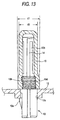
- Fig. 13 a second example of the related-art antenna structure for fixing the cap to the core member will be described.
- same or equivalent members to those in Fig. 12 will be denoted with same reference numbers, and repetitive explanation will be omitted.
- a male thread 10d is engraved on the outer peripheral face of the core member 10 in an intermediate part thereof, close to the position where the core member is projected from the casing body 12.
- a female thread 16b which is adapted to be screwed with the male thread 10d is engraved on the inner peripheral face of the cap 16 adjacent to the opening end thereof. The cap 16 is fitted over the core member 10, and the male thread 10d is tightly screwed with the female thread 16b, thereby to fix the cap 16 to the core member 10.
- fixing and retaining force for the cap 16 depends on mechanical strength in a radial direction of the opening end of the cap 16 where the groove 16a or the female thread 16b is provided. This means that reducing a thickness of the cap 16 at the opening end may result in decrease of the retaining force. Therefore, under the present circumstances, an outer diameter d1 of the cap 16 at the opening end side is necessarily required to be larger than an outer diameter d2 of the cap 16 in the intermediate part and at the distal end side.
- the outer diameter d1 of the cap 16 at the opening end side becomes large in the related-art examples, there is such an inconvenience that a mounting area of the antenna to the casing body 12 becomes large accordingly, and freeness of designing an outer appearance of the cap 16 is restricted.
- elasticity is required for the cap 16 to be press-fitted, and so, material for the cap 16 is limited to an elastomer of insulating resin.
- a fixed position of the cap 16 in the circumferential direction of the core member 10 may be indefinite. This would be a drawback especially in a case where a logotype mark is put on the cap 16.
- an antenna comprising:
- a core member 20 is molded with insulative resin.
- a tongue piece 20a is formed at a base end side of the core member 20, which is to be fitted with a bore 22a of a casing body 22 for preventing the core member 20 from being slipped from the casing body 22.
- a pair of projections 20c are formed on an outer peripheral face of a cylindrical body 20b of the core member 20. The projections 20c are situated at opposite positions in the circumferential direction of the cylindrical body 20b.
- An antenna element 14 is disposed on the outer peripheral face of the cylindrical body 20b. Although it is not shown, one end of the antenna element 14 is electrically connected to a circuitry provided in the casing body 22 as an antenna output terminal.
- a cap 24 is molded with insulative resin so as to have a cylindrical shape in which an outer diameter is made uniform entirely in the longitudinal direction thereof.
- a pair of holes 24a are formed in the vicinity of an opening end of the cap 24. The holes 24a are situated at opposite positions in the circumferential direction of the cap 24.
- a pair of outer dies 28 are prepared.
- the dies 28 are provided with members 28a for forming the holes 24a.
- a core die 26 is disposed within a cavity 32 defined by the dies 28. Molten resin is injected into the cavity 32 via a gate 30 to form the cap 24.
- the outer dies 28 are laterally moved to open the cavity 32. In this condition, the molded cap 24 can be easily separated upward from the core die 26.
- the casing body 22 is provided with a restraining bore 22b which is continued from the bore 22a.
- the restraining bore 22b has a diameter which is slightly larger than the diameter of the bore 22a and the outer diameter of the opening end of the cap 24.
- the cap 24 is fitted over the core member 20 to cover the antenna element 14, such that the projections 20c are fitted into the holes 24a.
- the base end of the core member 20 is inserted into the bore 22a of the casing body 22, so that the opening end of the cap 24 is inserted into the restraining bore 22b.
- the tongue piece 20a which has been elastically deformed upon the passage through the bore 22a is restored to engage with the casing body 22 to prevent the core member 20 from slipping off.
- the inner face of the restraining bore 22b prevents the opening end side of the cap 24 from deforming outward.
- the outer diameter of the cap 24 at the opening end will not become larger than that of the intermediate part and the distal end side. Accordingly, the mounting area of the antenna on the casing body 22 can be made smaller. Moreover, there will be less restriction in designing the outer appearance. Further, it would be sufficient that the cap 24 is slightly press-fitted to the core member 20, and as the material of the cap 24, polycarbonate and ABS resins may be also employed, but not limited to an elastomer. Additionally, because the opening end of the cap 24 is inserted into the restraining bore 22b, a length of the cap 24 protruding from the casing body 22 can be reduced.
- the length protruding from the casing body is the same as that of the related-art antenna structure as shown in Figs. 12 and 13, the length of the antenna element 14 in a protruding direction can be made longer, and receiving sensitivity can be enhanced accordingly.
- Fig. 5 shows a first modified example of the antenna structure in the first embodiment.
- the casing body 22 is provided with a mount 22c which is projected outwardly to form the restraining bore 22b.
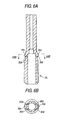
- Figs. 6A and 6B show a second modified example of the antenna structure in the first embodiment.
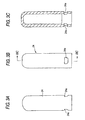
- slits 20d are formed in the cylindrical body 20b of the core member 20 such that the distal-side ends of the projections 20c are supported on the cylindrical body 20b in a cantilevered manner. Since the cantilevered projections 20c are deformed inward when the cap 24 is fitted over the core member 20, less or no elasticity is required for the cap 24. Therefore, selection of the material can be made free, which is preferable for making the outer diameter of the cap 24 smaller.
- Fig. 7 shows a third modified example of the antenna structure in the first embodiment.
- the outer peripheral surface of the cylindrical body 20b is formed with recesses 20e at opposite positions in the circumferential direction thereof.
- the inner peripheral face of the cap 24 is provided with projections 24b. When the cap 24 is fitted over the core member 20, the projections 24b are fitted into the recesses 20e.
- the restraining bore 22b prevents the opening end of the cap 24 from being deformed outward, thereby preventing the disengagement of the cap 24 from the core member 20.
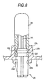
- a protrusion 20f is formed on the outer peripheral face of the cylindrical body 20b entirely in the circumferential direction thereof.
- a groove 24c is formed on the inner peripheral face of the cap 24 entirely in the circumferential direction.
- Fig. 9 shows a modified example of the antenna structure in the second embodiment.
- a groove 20g is formed on the outer peripheral face of the core member 20 entirely in the circumferential direction thereof, while a protrusion 24d is formed on the inner peripheral face of the cap 24 entirely in the circumferential direction.
- FIG. 10 a third embodiment of the invention will be described with reference to Fig. 10.
- This embodiment is different from the antenna structure in the first embodiment, in that an annular member 34 having no elastically is arranged on the outer peripheral face of the cap 24 at the opening end thereof, instead of restraining the outward deformation of the outer peripheral face of the cap 24 at the opening end by the casing body 22.
- the annular member 34 may be engaged in a state where the cap 24 has been fitted to the core member 20, or the annular member 34 may be appropriately tightened to be secured.
- the opening end of the cap 24 will be unable to be deformed outwardly by the annular member 34, and the engagement will not be released.
- the casing body 22 need not be provided with the restraining bore 22b.
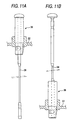
- the antenna structure in the above described embodiments are of such a type that the antenna structure is fixed to the casing body 22 in a state protruded outwardly (so-called STUB type).
- the antenna structure may be constructed in a so-called bottom loading type, by arranging an antenna rod 38 at a position of a center axis of an antenna structure 36 so as to be retractably extended from the casing body 22.
- the core member 20 may be formed in a tubular shape into which the antenna 38 can be inserted, although a specific structure is not shown in the drawing.
- a known technique of this type can be employed.
- the structure of the antenna element 14 in the above described embodiments may be in any shape, being not only in a meander shape, as shown in the drawings, but also in a coil shape.
- the structure for retaining the core member 20 on the casing body 22 may be in any type, including not only the tongue piece 20a as in the above embodiments, but also a male thread formed in the base end part of the core member 20 to be screwed with a female thread formed in the casing body 22.
Landscapes
- Engineering & Computer Science (AREA)
- Computer Networks & Wireless Communication (AREA)
- Support Of Aerials (AREA)
- Details Of Aerials (AREA)
Applications Claiming Priority (2)
| Application Number | Priority Date | Filing Date | Title |
|---|---|---|---|
| JP2003338499 | 2003-09-29 | ||
| JP2003338499A JP4141930B2 (ja) | 2003-09-29 | 2003-09-29 | アンテナ構造 |
Publications (1)
| Publication Number | Publication Date |
|---|---|
| EP1519442A1 true EP1519442A1 (de) | 2005-03-30 |
Family
ID=34191591
Family Applications (1)
| Application Number | Title | Priority Date | Filing Date |
|---|---|---|---|
| EP04022824A Withdrawn EP1519442A1 (de) | 2003-09-29 | 2004-09-24 | Antennenstruktur |
Country Status (5)
| Country | Link |
|---|---|
| US (1) | US7081856B2 (de) |
| EP (1) | EP1519442A1 (de) |
| JP (1) | JP4141930B2 (de) |
| KR (1) | KR100809512B1 (de) |
| CN (1) | CN1604392A (de) |
Cited By (2)
| Publication number | Priority date | Publication date | Assignee | Title |
|---|---|---|---|---|
| DE102005018052B4 (de) * | 2005-04-19 | 2010-09-23 | Aeromaritime Systembau Gmbh | Antennenkappe für U-Boote und Verfahren zum Herstellen einer Antennenkappe für U-Boote |
| US8692722B2 (en) | 2011-02-01 | 2014-04-08 | Phoenix Contact Development and Manufacturing, Inc. | Wireless field device or wireless field device adapter with removable antenna module |
Families Citing this family (1)
| Publication number | Priority date | Publication date | Assignee | Title |
|---|---|---|---|---|
| SG10201906867RA (en) * | 2019-07-25 | 2021-02-25 | Pci Private Ltd | Method for manufacturing electronic device |
Citations (3)
| Publication number | Priority date | Publication date | Assignee | Title |
|---|---|---|---|---|
| US5341149A (en) * | 1991-03-25 | 1994-08-23 | Nokia Mobile Phones Ltd. | Antenna rod and procedure for manufacturing same |
| EP0997970A1 (de) * | 1997-01-28 | 2000-05-03 | Yokowo Co., Ltd. | Antenne zum anbau an einem fahrzeug, antennenelement und herstellungsverfahren dafür |
| EP1143557A1 (de) * | 1999-10-25 | 2001-10-10 | Nippon Antena Kabushiki Kaisha | Helixantenne |
Family Cites Families (3)
| Publication number | Priority date | Publication date | Assignee | Title |
|---|---|---|---|---|
| US5977931A (en) * | 1997-07-15 | 1999-11-02 | Antenex, Inc. | Low visibility radio antenna with dual polarization |
| KR100355007B1 (ko) * | 2000-04-08 | 2002-11-18 | 주식회사 엠알더블유테크놀로지 | 무선 송, 수신기용 안테나 |
| JP3892685B2 (ja) * | 2001-07-26 | 2007-03-14 | 株式会社東芝 | ヘリカルアンテナ及び携帯端末装置 |
-
2003
- 2003-09-29 JP JP2003338499A patent/JP4141930B2/ja not_active Expired - Fee Related
-
2004
- 2004-09-24 EP EP04022824A patent/EP1519442A1/de not_active Withdrawn
- 2004-09-28 CN CNA2004100855951A patent/CN1604392A/zh active Pending
- 2004-09-28 US US10/950,433 patent/US7081856B2/en not_active Expired - Fee Related
- 2004-09-30 KR KR1020040077787A patent/KR100809512B1/ko not_active Expired - Fee Related
Patent Citations (3)
| Publication number | Priority date | Publication date | Assignee | Title |
|---|---|---|---|---|
| US5341149A (en) * | 1991-03-25 | 1994-08-23 | Nokia Mobile Phones Ltd. | Antenna rod and procedure for manufacturing same |
| EP0997970A1 (de) * | 1997-01-28 | 2000-05-03 | Yokowo Co., Ltd. | Antenne zum anbau an einem fahrzeug, antennenelement und herstellungsverfahren dafür |
| EP1143557A1 (de) * | 1999-10-25 | 2001-10-10 | Nippon Antena Kabushiki Kaisha | Helixantenne |
Cited By (2)
| Publication number | Priority date | Publication date | Assignee | Title |
|---|---|---|---|---|
| DE102005018052B4 (de) * | 2005-04-19 | 2010-09-23 | Aeromaritime Systembau Gmbh | Antennenkappe für U-Boote und Verfahren zum Herstellen einer Antennenkappe für U-Boote |
| US8692722B2 (en) | 2011-02-01 | 2014-04-08 | Phoenix Contact Development and Manufacturing, Inc. | Wireless field device or wireless field device adapter with removable antenna module |
Also Published As
| Publication number | Publication date |
|---|---|
| CN1604392A (zh) | 2005-04-06 |
| US20050078040A1 (en) | 2005-04-14 |
| JP4141930B2 (ja) | 2008-08-27 |
| KR100809512B1 (ko) | 2008-03-04 |
| KR20050031442A (ko) | 2005-04-06 |
| JP2005109737A (ja) | 2005-04-21 |
| US7081856B2 (en) | 2006-07-25 |
Similar Documents
| Publication | Publication Date | Title |
|---|---|---|
| US6679726B1 (en) | Panel mounted electrical connector | |
| JPH08144918A (ja) | 内燃機関用点火装置 | |
| US6231223B1 (en) | Intermediate fastening element for fitting a reflector on a support element of a headlamp | |
| JPH0228039A (ja) | 自動車の車体へ自動車持上げ装置の支持腕を当てるための栓 | |
| US7081856B2 (en) | Antenna structure | |
| KR970028556A (ko) | 전자 센서 및 그 제조 금형 | |
| KR100698857B1 (ko) | 안테나 및 그 제조 방법 | |
| JP3140343B2 (ja) | コネクタ装置 | |
| JP3844094B2 (ja) | 点火コイルの高圧端子側接続装置 | |
| JP3180026B2 (ja) | 防水コネクタ用閉塞栓 | |
| JPH10215116A (ja) | アンテナエレメントおよびその製造方法 | |
| JP2592523Y2 (ja) | コード保持構造 | |
| CN223625968U (zh) | 麦克风发射器及其壳体 | |
| JPH019347Y2 (de) | ||
| JP2000031715A (ja) | アンテナエレメントおよびその製造方法 | |
| JPH0524139Y2 (de) | ||
| JPS6011566Y2 (ja) | 差込プラグ | |
| JP3179343B2 (ja) | ヘリカルアンテナおよび該ヘリカルアンテナを先端に設けたアンテナ装置 | |
| JP2737668B2 (ja) | ゴム栓 | |
| EP4287413A1 (de) | Anschlussklemme, anschlussklemmenanordnung, kabelanordnung und ladesitz | |
| JP2595351Y2 (ja) | 同軸コネクタ | |
| JP4132399B2 (ja) | 無線機用アンテナ取付構造 | |
| US20020053990A1 (en) | Cellular-phone apparatus and antenna used for this | |
| JPH0115085Y2 (de) | ||
| KR200187287Y1 (ko) | 커버 및 소켓 플러그 일체형 안테나 |
Legal Events
| Date | Code | Title | Description |
|---|---|---|---|
| PUAI | Public reference made under article 153(3) epc to a published international application that has entered the european phase |
Free format text: ORIGINAL CODE: 0009012 |
|
| AK | Designated contracting states |
Kind code of ref document: A1 Designated state(s): AT BE BG CH CY CZ DE DK EE ES FI FR GB GR HU IE IT LI LU MC NL PL PT RO SE SI SK TR |
|
| AX | Request for extension of the european patent |
Extension state: AL HR LT LV MK |
|
| AKX | Designation fees paid | ||
| REG | Reference to a national code |
Ref country code: DE Ref legal event code: 8566 |
|
| STAA | Information on the status of an ep patent application or granted ep patent |
Free format text: STATUS: THE APPLICATION IS DEEMED TO BE WITHDRAWN |
|
| 18D | Application deemed to be withdrawn |
Effective date: 20051005 |