EP1519432A2 - Electrode - Google Patents
Electrode Download PDFInfo
- Publication number
- EP1519432A2 EP1519432A2 EP04019949A EP04019949A EP1519432A2 EP 1519432 A2 EP1519432 A2 EP 1519432A2 EP 04019949 A EP04019949 A EP 04019949A EP 04019949 A EP04019949 A EP 04019949A EP 1519432 A2 EP1519432 A2 EP 1519432A2
- Authority
- EP
- European Patent Office
- Prior art keywords
- electrode
- fuel
- anode
- cell
- fuel cell
- Prior art date
- Legal status (The legal status is an assumption and is not a legal conclusion. Google has not performed a legal analysis and makes no representation as to the accuracy of the status listed.)
- Withdrawn
Links
Images


Classifications
-
- H—ELECTRICITY
- H01—ELECTRIC ELEMENTS
- H01M—PROCESSES OR MEANS, e.g. BATTERIES, FOR THE DIRECT CONVERSION OF CHEMICAL ENERGY INTO ELECTRICAL ENERGY
- H01M8/00—Fuel cells; Manufacture thereof
- H01M8/22—Fuel cells in which the fuel is based on materials comprising carbon or oxygen or hydrogen and other elements; Fuel cells in which the fuel is based on materials comprising only elements other than carbon, oxygen or hydrogen
-
- H—ELECTRICITY
- H01—ELECTRIC ELEMENTS
- H01M—PROCESSES OR MEANS, e.g. BATTERIES, FOR THE DIRECT CONVERSION OF CHEMICAL ENERGY INTO ELECTRICAL ENERGY
- H01M4/00—Electrodes
- H01M4/86—Inert electrodes with catalytic activity, e.g. for fuel cells
- H01M4/8605—Porous electrodes
-
- H—ELECTRICITY
- H01—ELECTRIC ELEMENTS
- H01M—PROCESSES OR MEANS, e.g. BATTERIES, FOR THE DIRECT CONVERSION OF CHEMICAL ENERGY INTO ELECTRICAL ENERGY
- H01M4/00—Electrodes
- H01M4/86—Inert electrodes with catalytic activity, e.g. for fuel cells
- H01M4/88—Processes of manufacture
- H01M4/8825—Methods for deposition of the catalytic active composition
- H01M4/8853—Electrodeposition
-
- H—ELECTRICITY
- H01—ELECTRIC ELEMENTS
- H01M—PROCESSES OR MEANS, e.g. BATTERIES, FOR THE DIRECT CONVERSION OF CHEMICAL ENERGY INTO ELECTRICAL ENERGY
- H01M4/00—Electrodes
- H01M4/86—Inert electrodes with catalytic activity, e.g. for fuel cells
- H01M4/88—Processes of manufacture
- H01M4/8878—Treatment steps after deposition of the catalytic active composition or after shaping of the electrode being free-standing body
- H01M4/8892—Impregnation or coating of the catalyst layer, e.g. by an ionomer
-
- H—ELECTRICITY
- H01—ELECTRIC ELEMENTS
- H01M—PROCESSES OR MEANS, e.g. BATTERIES, FOR THE DIRECT CONVERSION OF CHEMICAL ENERGY INTO ELECTRICAL ENERGY
- H01M4/00—Electrodes
- H01M4/86—Inert electrodes with catalytic activity, e.g. for fuel cells
- H01M4/90—Selection of catalytic material
- H01M4/92—Metals of platinum group
- H01M4/921—Alloys or mixtures with metallic elements
-
- H—ELECTRICITY
- H01—ELECTRIC ELEMENTS
- H01M—PROCESSES OR MEANS, e.g. BATTERIES, FOR THE DIRECT CONVERSION OF CHEMICAL ENERGY INTO ELECTRICAL ENERGY
- H01M4/00—Electrodes
- H01M4/86—Inert electrodes with catalytic activity, e.g. for fuel cells
- H01M4/90—Selection of catalytic material
- H01M4/92—Metals of platinum group
- H01M4/925—Metals of platinum group supported on carriers, e.g. powder carriers
- H01M4/926—Metals of platinum group supported on carriers, e.g. powder carriers on carbon or graphite
-
- H—ELECTRICITY
- H01—ELECTRIC ELEMENTS
- H01M—PROCESSES OR MEANS, e.g. BATTERIES, FOR THE DIRECT CONVERSION OF CHEMICAL ENERGY INTO ELECTRICAL ENERGY
- H01M4/00—Electrodes
- H01M4/86—Inert electrodes with catalytic activity, e.g. for fuel cells
- H01M4/90—Selection of catalytic material
- H01M4/92—Metals of platinum group
- H01M4/928—Unsupported catalytic particles; loose particulate catalytic materials, e.g. in fluidised state
-
- H—ELECTRICITY
- H01—ELECTRIC ELEMENTS
- H01M—PROCESSES OR MEANS, e.g. BATTERIES, FOR THE DIRECT CONVERSION OF CHEMICAL ENERGY INTO ELECTRICAL ENERGY
- H01M8/00—Fuel cells; Manufacture thereof
- H01M8/04—Auxiliary arrangements, e.g. for control of pressure or for circulation of fluids
- H01M8/04082—Arrangements for control of reactant parameters, e.g. pressure or concentration
- H01M8/04186—Arrangements for control of reactant parameters, e.g. pressure or concentration of liquid-charged or electrolyte-charged reactants
-
- H—ELECTRICITY
- H01—ELECTRIC ELEMENTS
- H01M—PROCESSES OR MEANS, e.g. BATTERIES, FOR THE DIRECT CONVERSION OF CHEMICAL ENERGY INTO ELECTRICAL ENERGY
- H01M8/00—Fuel cells; Manufacture thereof
- H01M8/10—Fuel cells with solid electrolytes
- H01M8/1004—Fuel cells with solid electrolytes characterised by membrane-electrode assemblies [MEA]
-
- H—ELECTRICITY
- H01—ELECTRIC ELEMENTS
- H01M—PROCESSES OR MEANS, e.g. BATTERIES, FOR THE DIRECT CONVERSION OF CHEMICAL ENERGY INTO ELECTRICAL ENERGY
- H01M8/00—Fuel cells; Manufacture thereof
- H01M8/10—Fuel cells with solid electrolytes
- H01M8/1009—Fuel cells with solid electrolytes with one of the reactants being liquid, solid or liquid-charged
-
- H—ELECTRICITY
- H01—ELECTRIC ELEMENTS
- H01M—PROCESSES OR MEANS, e.g. BATTERIES, FOR THE DIRECT CONVERSION OF CHEMICAL ENERGY INTO ELECTRICAL ENERGY
- H01M8/00—Fuel cells; Manufacture thereof
- H01M8/10—Fuel cells with solid electrolytes
- H01M8/1016—Fuel cells with solid electrolytes characterised by the electrolyte material
- H01M8/1018—Polymeric electrolyte materials
- H01M8/102—Polymeric electrolyte materials characterised by the chemical structure of the main chain of the ion-conducting polymer
- H01M8/1023—Polymeric electrolyte materials characterised by the chemical structure of the main chain of the ion-conducting polymer having only carbon, e.g. polyarylenes, polystyrenes or polybutadiene-styrenes
-
- H—ELECTRICITY
- H01—ELECTRIC ELEMENTS
- H01M—PROCESSES OR MEANS, e.g. BATTERIES, FOR THE DIRECT CONVERSION OF CHEMICAL ENERGY INTO ELECTRICAL ENERGY
- H01M8/00—Fuel cells; Manufacture thereof
- H01M8/10—Fuel cells with solid electrolytes
- H01M8/1016—Fuel cells with solid electrolytes characterised by the electrolyte material
- H01M8/1018—Polymeric electrolyte materials
- H01M8/1039—Polymeric electrolyte materials halogenated, e.g. sulfonated polyvinylidene fluorides
-
- H—ELECTRICITY
- H01—ELECTRIC ELEMENTS
- H01M—PROCESSES OR MEANS, e.g. BATTERIES, FOR THE DIRECT CONVERSION OF CHEMICAL ENERGY INTO ELECTRICAL ENERGY
- H01M8/00—Fuel cells; Manufacture thereof
- H01M8/10—Fuel cells with solid electrolytes
- H01M8/1016—Fuel cells with solid electrolytes characterised by the electrolyte material
- H01M8/1018—Polymeric electrolyte materials
- H01M8/1041—Polymer electrolyte composites, mixtures or blends
- H01M8/1046—Mixtures of at least one polymer and at least one additive
-
- H—ELECTRICITY
- H01—ELECTRIC ELEMENTS
- H01M—PROCESSES OR MEANS, e.g. BATTERIES, FOR THE DIRECT CONVERSION OF CHEMICAL ENERGY INTO ELECTRICAL ENERGY
- H01M8/00—Fuel cells; Manufacture thereof
- H01M8/24—Grouping of fuel cells, e.g. stacking of fuel cells
- H01M8/2455—Grouping of fuel cells, e.g. stacking of fuel cells with liquid, solid or electrolyte-charged reactants
-
- H—ELECTRICITY
- H01—ELECTRIC ELEMENTS
- H01M—PROCESSES OR MEANS, e.g. BATTERIES, FOR THE DIRECT CONVERSION OF CHEMICAL ENERGY INTO ELECTRICAL ENERGY
- H01M4/00—Electrodes
- H01M4/86—Inert electrodes with catalytic activity, e.g. for fuel cells
- H01M2004/8678—Inert electrodes with catalytic activity, e.g. for fuel cells characterised by the polarity
- H01M2004/8684—Negative electrodes
-
- H—ELECTRICITY
- H01—ELECTRIC ELEMENTS
- H01M—PROCESSES OR MEANS, e.g. BATTERIES, FOR THE DIRECT CONVERSION OF CHEMICAL ENERGY INTO ELECTRICAL ENERGY
- H01M2300/00—Electrolytes
- H01M2300/0017—Non-aqueous electrolytes
- H01M2300/0065—Solid electrolytes
- H01M2300/0082—Organic polymers
-
- H—ELECTRICITY
- H01—ELECTRIC ELEMENTS
- H01M—PROCESSES OR MEANS, e.g. BATTERIES, FOR THE DIRECT CONVERSION OF CHEMICAL ENERGY INTO ELECTRICAL ENERGY
- H01M8/00—Fuel cells; Manufacture thereof
- H01M8/04—Auxiliary arrangements, e.g. for control of pressure or for circulation of fluids
- H01M8/04082—Arrangements for control of reactant parameters, e.g. pressure or concentration
- H01M8/04089—Arrangements for control of reactant parameters, e.g. pressure or concentration of gaseous reactants
- H01M8/04119—Arrangements for control of reactant parameters, e.g. pressure or concentration of gaseous reactants with simultaneous supply or evacuation of electrolyte; Humidifying or dehumidifying
-
- Y—GENERAL TAGGING OF NEW TECHNOLOGICAL DEVELOPMENTS; GENERAL TAGGING OF CROSS-SECTIONAL TECHNOLOGIES SPANNING OVER SEVERAL SECTIONS OF THE IPC; TECHNICAL SUBJECTS COVERED BY FORMER USPC CROSS-REFERENCE ART COLLECTIONS [XRACs] AND DIGESTS
- Y02—TECHNOLOGIES OR APPLICATIONS FOR MITIGATION OR ADAPTATION AGAINST CLIMATE CHANGE
- Y02E—REDUCTION OF GREENHOUSE GAS [GHG] EMISSIONS, RELATED TO ENERGY GENERATION, TRANSMISSION OR DISTRIBUTION
- Y02E60/00—Enabling technologies; Technologies with a potential or indirect contribution to GHG emissions mitigation
- Y02E60/30—Hydrogen technology
- Y02E60/50—Fuel cells
-
- Y—GENERAL TAGGING OF NEW TECHNOLOGICAL DEVELOPMENTS; GENERAL TAGGING OF CROSS-SECTIONAL TECHNOLOGIES SPANNING OVER SEVERAL SECTIONS OF THE IPC; TECHNICAL SUBJECTS COVERED BY FORMER USPC CROSS-REFERENCE ART COLLECTIONS [XRACs] AND DIGESTS
- Y02—TECHNOLOGIES OR APPLICATIONS FOR MITIGATION OR ADAPTATION AGAINST CLIMATE CHANGE
- Y02P—CLIMATE CHANGE MITIGATION TECHNOLOGIES IN THE PRODUCTION OR PROCESSING OF GOODS
- Y02P70/00—Climate change mitigation technologies in the production process for final industrial or consumer products
- Y02P70/50—Manufacturing or production processes characterised by the final manufactured product
Definitions
- the invention generally relates to organic fuel cells and in particular liquid feed organic fuel cells.
- Fuel cells are electrochemical cells in which a free energy change resulting from a fuel oxidation reaction is converted into electrical energy.
- an organic fuel such as methanol, formaldehyde, or formic acid is oxidized to carbon dioxide at an anode, while air or oxygen is reduced to water at a cathode.
- Fuel cells employing organic fuels are extremely attractive for both stationary and portable applications, in part, because of the high specific energy of the organic fuels, e.g., the specific energy of methanol is 6232 Wh/kg.
- Direct oxidation fuel cells do not require a fuel processing stage. Hence, direct oxidation fuel cells offer a considerable weight and volume advantage over the indirect fuel cells. Direct oxidation fuel cells use either a vapor or a liquid feed of the organic fuel. Current art direct oxidation fuel cells that have shown promise typically employ a liquid feed design in which a liquid mixture of the organic fuel and a sulfuric acid electrolyte is circulated past the anode of the fuel cell.
- sulfuric acid electrolyte in the current-art direct methanol fuel cells presents several problems.
- the use of sulfuric acid which is highly corrosive, places significant constraints on the materials of construction of the fuel cell. Typically, expensive corrosion resistant materials are required.
- Sulfate anions, created within the fuel cell have a strong tendency to adsorb on the electrocatalyst, thereby hindering the kinetics of electro-oxidation of the fuel and resulting in poor performance of the fuel electrode.
- sulfuric acid tends to degrade at temperatures greater than 80°C and the products of degradation usually contain sulfur which can poison the electrocatalyst. In multi-cell stacks, the use of sulfuric acid electrolyte can result in parasitic shunt currents.
- U.S. Patents 3,013,908 and 3,113,049 describe liquid feed direct methanol fuel cells using a sulfuric acid electrolyte.
- U.S. Patents 4,262,063, 4,390,603, 4,478,917 and 4,629,664 describe improvements to sulfuric acid-based methanol fuel cells wherein a high molecular weight electrolyte or a solid proton conducting membrane is interposed between the cathode and the anode as an ionically conducting layer to reduce crossover of the organic fuel from the anode to the cathode.
- the ionically conducting layer helps reduce crossover, the ionically conducting layer is used only in conjunction with a sulfuric acid electrolyte.
- the fuel cell suffers from the various aforementioned disadvantages of using sulfuric acid as an electrolyte.
- the conventional method of fabricating high-surface-area electro-catalytic electrodes for use such fuel cells also needs to be improved.
- the existing method of fabrication of fuel cell electrodes is a fairly time-consuming and expensive procedure. Specifically, electrode fabrication requires that a high surface-area carbon-supported alloy powder be initially prepared by a chemical method which usually requires about 24 hours. Once prepared, the carbon-supported alloy powder is combined with a TeflonTM binder and applied to a carbon fiber-based support to yield a gas diffusion electrode. To volatilize impurities arising out of the TeflonTM binder and to obtain a fibrous matrix of TeflonTM, the electrodes are heated to 200-300°C. During this heating step, oxidation and sintering of the electrocatalyst can occur, resulting in a reduced activity of the surface of the electrode. Thus, the electrodes often require re-activation before use.
- Electrodes produced by conventional methods are usually of the gas-diffusion type and cannot be effectively used in liquid feed type fuel cells as the electrode is not adequately wetted by the liquid fuel.
- the structure and properties of a fuel oxidation electrode (anode) for use in liquid feed type fuel cells are quite different from the gas/vapor feed fuel cells such as the hydrogen/oxygen fuel cell.
- the electrode structures for use in a liquid feed fuel cell should be very porous and the liquid fuel solution should wet all pores. Carbon dioxide that is evolved at the fuel electrode should be effectively released from the zone of reaction. Adequate wetting of the electrodes is a major problem for liquid feed fuel cells-- even for those which use a sulfuric acid electrolyte.
- a general object of the invention is to provide an improved direct type liquid feed fuel cell.
- One particular object of the invention is to provide a direct type liquid feed fuel cell which does not require a sulfuric acid electrolyte.
- Another particular object of the invention is to achieve adequate wetting of electrodes for use in liquid feed fuel cells.
- Yet another particular object of the invention is to provide an improved method for wetting electrodes for use in fuel cells having sulfuric acid electrolytes.
- Still another particular object of the invention is to provide improved fuels for use in liquid feed fuel cells.
- the object of providing an improved liquid feed direct fuel cell which does not require a sulfuric acid electrolyte is achieved in part by using a solid polymer electrolyte membrane in combination with a battery-type anode that is porous and is capable of wetting the fuel.
- a battery-type anode structure and a cathode are bonded to either side of the solid polymer proton-conducting membrane forming a membrane-electrode assembly.
- a solution of methanol and water which is substantially free of sulfuric acid is circulated past the anode side of the assembly.
- a solid polymer membrane is used, in part, because such membranes have excellent electrochemical and mechanical stability, high ionic conductivity, and can function both as an electrolyte and as a separator. Also, the kinetics of electro-oxidation of methanol and electro-reduction of air or oxygen are more facile at an electrode/membrane-electrolyte interface as compared to an electrode/sulfuric acid interface.
- the use of the membrane permits operation of the fuel cell at temperatures as high as 120°C. Since the fuel and water solution is substantially free of sulfuric acid, there is no need for expensive corrosion-resistant components in the fuel cell and its accessories. Also the absence of conducting ions in the fuel and water solutions, which can exist when a sulfuric acid electrolyte is employed, substantially eliminates the possibility of any parasitic shunt currents in a multi-cell stack.
- the solid polymer electrolyte is preferably a proton-conducting cation-exchange membrane, such as the perflourinated sulfonic acid polymer membrane, NafionTM.
- NafionTM is a co-polymer of tetrafluoroethylene and perfluorovinylether sulfonic acid.
- Membranes of modified perflourinated sulfonic acid polymer, polyhydrocarbon sulfonic acid and composites of two or more kinds of proton exchange membranes can also be used.
- the anode is preferably formed from high surface area particles of platinum-based alloys of noble and non-noble metals.
- Binary and ternary compositions can be used for the electro-oxidation of organic fuels.
- Platinum-ruthenium alloy, with compositions varying from 10 - 90 atom percent of platinum, is the preferred anode electrocatalyst for the electro-oxidation of methanol.
- the alloy particles are either in the form of fine metal powders, i.e., "unsupported", or are supported on high surface area carbon material.
- NafionTM with an equivalent weight of 1000 or higher is the preferred substance.
- the additive decreases interfacial tension of the liquid/catalyst interface and leads to the uniform wetting of the electrode pores and particles by the fuel and water solution, yielding enhanced utilization of the electrocatalyst.
- NafionTM additive also provides ionic continuity with the solid electrolyte membrane and permits efficient transport of protons or hydronium ions generated by the fuel oxidation reaction.
- the additive facilitates the release of carbon dioxide from the pores of the electrode.
- anionic groups are not strongly adsorbed on the electrode/electrolyte interface. Consequently, the kinetics of electro-oxidation of methanol are more facile than in sulfuric acid electrolyte.
- Other hydrophilic proton-conducting additives with the desired properties include montmorrolinite clay, alkoxycelluloses, cyclodextrins, mixtures of zeolites, and zirconium hydrogen phosphate.
- the object of improving electrodes for operating in liquid feed fuel cells is achieved, in part, by using perfluorooctanesulfonic acid as an additive in an electro-deposition bath used in fabricating the electrode.
- An electro-deposition method using the perfluorooctanesulfonic acid additive comprises the steps of positioning a high-surface-area carbon electrode structure within a bath containing metallic salts, positioning an anode within the bath and applying a voltage between the anode and the cathode until a desired amount of metal becomes deposited onto the electrode. After deposition of the metal onto the electrode, the electrode is extracted from the bath and washed within deionized water.
- the metal salts include hydrogen hexachloroplatinate and potassium pentachloroaquoruthenium.
- the anode is composed of platinum.
- the carbon electrode structure includes high-surface-area carbon particles bound together by polytetrafluoroethylene, sold under the trademark TeflonTM.
- the object of providing for adequate wetting of an electrode within a liquid feed fuel cell having a sulfuric acid electrolyte is achieved by employing perfluorooctanesulfonic acid as an sadditive to the fuel mixture of the fuel cell.
- the perfluorooctanesulfonic acid is added to the organic fuel and water mixture in concentrations from 0.001 - 0.1 M.
- trimethoxymethane, dimethoxymethane or trioxane All three new fuels can be oxidized at a high rate into carbon dioxide and water within the fuel cell without poisoning the electrodes. Furthermore, neither trimethoxymethane, dimethoxymethane or trioxane are corrosive. Rates of oxidation of the three new fuels are comparable to, or better than, oxidation rates of conventional organic fuels. For example, rates of oxidation for dimethoxymethane are higher than that of methanol at the same temperature. Trioxane achieves oxidation rates comparable to that of formaldehyde. However, trioxane has a much higher molecular weight than formaldehyde and, as such, molecules of trioxane do not cross-over to the cathode of the fuel cell as easily as molecules of formaldehyde.
- Trimethoxymethane, dimethoxymethane and trioxane may be employed in a fuel cell having any of the improvements set forth above.
- the improved fuels may also be advantageously used within other organic fuel cells, including entirely conventional fuel cells.
- an improved liquid feed organic fuel cell using a solid polymeric electrolyte membrane and a ionomeric anode additive is described, primarily with reference to Figs. 1 - 6.
- a method for fabricating the anode having the ionomeric additive is described with reference to Figs. 7 - 8.
- a method for achieving improved wetting by fabricating an electrode within a bath containing perfluorooctanesulfonic acid is described with reference to Figs. 9 - 11.
- a fuel cell employing perfluorooctanesulfonic acid as a fuel additive is described with reference to Fig. 12.
- Fuel cells employing dimethoxymethane, trimethoxymethane and trioxane as fuels are described with reference to Figs. 13 - 21.
- Fig. 1 illustrates a liquid feed organic fuel cell 10 having a housing 12, an anode 14, a cathode 16 and a solid polymer proton-conducting cation-exchange electrolyte membrane 18.
- anode 14, cathode 16 and solid polymer electrolyte membrane 18 are preferably a single multi-layer composite structure, referred to herein as a membrane-electrode assembly.
- a pump 20 is provided for pumping an organic fuel and water solution into an anode chamber 22 of housing 12. The organic fuel and water mixture is withdrawn through an outlet port 23 and is re-circulated though a re-circulation system described below with reference to Fig. 2 which includes a methanol tank 19.
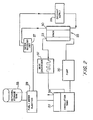
- Fig. 2 illustrates a fuel cell system incorporating a stack of individual fuel cells including the re-circulation system. The following detailed description of the fuel cell of Fig. 1 primarily focuses on the structure and function of anode 14, cathode 16 and membrane 18.
- anode chamber 22 Prior to use, anode chamber 22 is filled with the organic fuel and water mixture and cathode chamber 28 is filled with air or oxygen.
- the organic fuel is circulated past anode 14 while oxygen or air is pumped into chamber 28 and circulated past cathode 16.
- an electrical load (not shown) is connected between anode 14 and cathode 16
- electro-oxidation of the organic fuel occurs at anode 14 and electro-reduction of oxygen occurs at cathode 16.
- the occurrence of different reactions at the anode and cathode gives rise to a voltage difference between the two electrodes.
- Electrons generated by electro-oxidation at anode 14 are conducted through the external load (not shown) and are ultimately captured at cathode 16.
- Hydrogen ions or protons generated at anode 14 are transported directly across membrane electrolyte 18 to cathode 16.
- a flow of current is sustained by a flow of ions through the cell and electrons through the external load.
- membrane 18 is formed from NafionTM, a perfluorinated proton-exchange membrane material.
- NafionTM is a co-polymer of tetrafluoroethylene and perfluorovinylether sulfonic acid.
- Other membrane materials can also be used.
- membranes of modified perflourinated sulfonic acid polymer, polyhydrocarbon sulfonic acid and composites of two or more kinds of proton exchange membranes can be used.
- Anode 14 is formed from platinum-ruthenium alloy particles either as fine metal powders, i.e. "unsupported", or dispersed on high surface area carbon, i.e. "supported”.
- the high surface area carbon may be a material such as Vulcan XC-72A, provided by Cabot Inc., USA.
- a carbon fiber sheet backing (not shown) is used to make electrical contact with the particles of the electrocatalyst.
- Commercially available TorayTM paper is used as the electrode backing sheet.
- a supported alloy electrocatalyst on a TorayTM paper backing is available from E-Tek, Inc., of Framingham, Massachusetts.
- both unsupported and supported electrocatalysts may be prepared by chemical methods, combined with TeflonTM binder and spread on TorayTM paper backing to produce the anode.
- TeflonTM binder and spread on TorayTM paper backing to produce the anode.
- An efficient and time-saving method of fabrication of electro-catalytic electrodes is described in detail herein below.
- Platinum-based alloys in which a second metal is either tin, iridium, osmium, or rhenium can be used instead of platinum-ruthenium.
- the choice of the alloy depends on the fuel to be used in the fuel cell.
- Platinum-ruthenium is preferable for electro-oxidation of methanol.
- the loading of the alloy particles in the electrocatalyst layer is preferably in the range of 0.5 - 4.0 mg/cm 2 . More efficient electro-oxidation is realized at higher loading levels, rather than lower loading levels.
- Cathode 16 is a gas diffusion electrode in which platinum particles are bonded to one side of membrane 18.
- Cathode 16 is preferably formed from unsupported or supported platinum bonded to a side of membrane 18 opposite to anode 14.
- Unsupported platinum black (fuel cell grade) available from Johnson Matthey Inc., USA or supported platinum materials available from E-Tek Inc., USA are suitable for the cathode.
- the cathode metal particles are preferably mounted on a carbon backing material.
- the loading of the electrocatalyst particles onto the carbon backing is preferably in the range of 0.5-4.0 mg/cm 2 .
- the electrocatalyst alloy and the carbon fiber backing contain 10-50 weight percent TeflonTM to provide hydrophobicity needed to create a three-phase boundary and to achieve efficient removal of water produced by electro-reduction of oxygen.
- a fuel and water mixture (containing no acidic or alkaline electrolyte) in the concentration range of 0.5 - 3.0 mole/liter is circulated past anode 14 within anode chamber 22.
- flow rates in the range of 10 - 500 milliliters/min. are used.
- Carbon dioxide produced by the above reaction is withdrawn along with the fuel and water solution through outlet 23 and separated from the solution in a gas-liquid separator (described below with reference to Fig. 2).
- the fuel and water solution is then re-circulated into the cell by pump 20.
- oxygen or air is circulated past cathode 16 at pressures in the range of 10 to 30 psig. Pressures greater than ambient improve the mass transport of oxygen to the sites of electrochemical reactions, especially at high current densities. Water produced by electrochemical reaction at the cathode is transported out of cathode chamber 28 by flow of oxygen through port 30.
- Fuel crossover lowers the operating potential of the oxygen electrode and results in consumption of fuel without producing useful electrical energy. In general, fuel crossover is a parasitic reaction which lowers efficiency, reduces performance and generates heat in the fuel cell. It is therefore desirable to minimize the rate of fuel crossover.
- the rate of crossover is proportional to the permeability of the fuel through the solid electrolyte membrane and increases with increasing concentration and temperature.
- the permeability of the membrane to the liquid fuel can be reduced. Reduced permeability for the fuel results in a lower crossover rate. Also, fuels having a large molecular size have a smaller diffusion coefficient than fuels which have small molecular size. Hence, permeability can be reduced by choosing a fuel having a large molecular size. While water soluble fuels are desirable, fuels with moderate solubility exhibit lowered permeability. Fuels with high boiling points do not vaporize and their transport through the membrane is in the liquid phase. Since the permeability for vapors is higher than liquids, fuels with high boiling points generally have a low crossover rate. The concentration of the liquid fuel can also be lowered to reduce the crossover rate.
- anode structure With an optimum distribution of hydrophobic and hydrophilic sites, the anode structure is adequately wetted by the liquid fuel to sustain electrochemical reaction and excessive amounts of fuel are prevented from having access to the membrane electrolyte.
- an appropriate choice of anode structures can result in the high performance and desired low crossover rates.
- Protons generated at anode 14 and water produced at cathode 16 are transported between the two electrodes by proton-conducting solid electrolyte membrane 18.
- the maintenance of high proton conductivity of membrane 18 is important to the effective operation of an organic/air fuel cell.
- the water content of the membrane is maintained by providing contact directly with the liquid fuel and water mixture.
- the thickness of the proton-conducting solid polymer electrolyte membranes should be in the range from 0.05 - 0.5 mm to be dimensionally stable. Membranes thinner than 0.05 mm may result in membrane electrode assemblies which are poor in mechanical strength, while membranes thicker than 0.5 mm may suffer extreme and damaging dimensional changes induced by swelling of the polymer by the liquid fuel and water solutions and also exhibit excessive resistance.
- the ionic conductivity of the membranes should be greater than 1 ohm -1 cm -1 for the fuel cell to have a tolerable internal resistance. As noted above, the membrane should have a low permeability to the liquid fuel.
- a NafionTM membrane has been found to be effective as a proton-conducting solid polymer electrolyte membrane, perfluorinated sulfonic acid polymer membranes such as AciplexTM (manufactured by Asahi Glass Co., Japan) and polymer membranes made by Dow Chemical Co., USA, such as XUS13204.10 which are similar in properties to NafionTM are also applicable.
- Membranes of polyethylene and polypropylene sulfonic acid, polystyrene sulfonic acid and other polyhydrocarbon-based sulfonic acids can also be used depending on the temperature and duration of fuel cell operation.
- Composite membranes consisting of two or more types of proton-conducting cation-exchange polymers with differing acid equivalent weights, or varied chemical composition (such as modified acid group or polymer backbone), or varying water contents, or differing types and extents of cross-linking (such as cross linked by multivalent cations e.g., Al 3+, Mg 2+ etc.,) can be used to achieve low fuel permeability.
- Such composite membranes can be fabricated to achieve high ionic conductivity, low permeability for the liquid fuel and good electrochemical stability.
- a liquid feed direct oxidation organic fuel cell is achieved using a proton-conducting solid polymer membrane as electrolyte without the need for a free soluble acid or base electrolyte.
- the only electrolyte is the proton-conducting solid polymer membrane.
- No acid is present in free form in the liquid fuel and water mixture. Since no free acid is present, acid-induced corrosion of cell components, which can occur in current-art acid based organic/air fuel cells, is avoided.
- This offers considerable flexibility in the choice of materials for the fuel cell and the associated sub-systems.
- unlike fuel cells which contain potassium hydroxide as liquid electrolyte cell performance does not degrade because soluble carbonates are not formed. Also by the use of a solid electrolyte membrane, parasitic shunt currents are avoided.
- the fuel cell system includes a stack 25 of fuel cells, each having the membrane/electrode assembly described above with reference to Fig. 1.
- Oxygen or air is supplied by an oxidant supply 26 which may be, for example, a bottled oxygen supply, an air-blowing fan or an air compressor.
- An air and water or oxygen and water mixture is withdrawn from stack 25 through an outlet port 30 and conveyed to a water recovery unit 27.
- Water recovery unit 27 operates to separate the air or oxygen from the water. A portion of the air or oxygen separated by unit 27 is returned to oxidant supply 26 for re-entry into stack 25.
- Fresh air or oxygen is added to supply 27.
- Water separated by unit 27 is fed to a fuel and water injection unit 29 which also receives an organic fuel, such as methanol, from a storage tank 33.
- Injection unit 29 combines the water from recovery unit 27 with the organic fuel from tank 33, yielding a fuel and water solution with the fuel dissolved in the water.
- the fuel and water solution provided by injection unit 29 is fed into a circulation tank 35.
- a fuel and water mixture containing carbon dioxide is withdrawn through port 23 from stack 25 and is fed through a heat exchanger 37 and into circulation tank 35.
- circulation tank 35 receives both a fuel and water solution from injection unit 29 and a fuel and water solution containing a carbon dioxide gas from heat exchanger 37.
- Circulation tank 35 extracts carbon dioxide from the fuel and water mixture and releases the carbon dioxide through a vent 39.
- the resulting fuel and water solution is fed through pump 20 and into stack 25.
- Circulation tank 35 can also be located between stack 25 and heat exchanger 34 so as to remove the carbon dioxide before the heat exchanger and thereby improve performance of the heat exchanger.
- Circulation tank 35 is a tower having a large head space.
- the liquid fuel and water mixture received from injection unit 29 is added into a top of the tower.
- the fuel and water mixture having carbon dioxide therein is fed into a bottom portion of the tower.
- Carbon dioxide gas released from the fuel and water mixture is allowed to accumulate in the head space and is ultimately vented.
- the fuel and water mixture containing the carbon dioxide can be passed through a cluster of tubes of a microporous material such as CelgardTM or GoreTexTM which allows gases to be released through walls of the tubes of the microporous material, while the liquid fuel flows along an axis of the tubes.
- CelgardTM and GoreTexTM are registered trademarks of Celanese Corp. and Gore Association, USA.
- a static re-circulation system (not shown) can be employed within an anode chamber of stack 25 to separate carbon dioxide from the fuel and water mixture such that an external circulation tank need not be provided.
- bubbles of carbon dioxide due to innate buoyancy, tend to rise vertically within the anode chamber. Viscous interaction with the liquid fuel mixture surrounding the gas bubbles drags the liquid fuel upwards in the direction of outlet port 23.
- the liquid releases the gas, exchanges heat with the surroundings and cools, thereby becoming denser than the liquid in the cell.
- the denser liquid is fed into the bottom of the anode chamber through an inlet port.
- the static re-circulation system takes advantage of the heat and gas produced in the cell.
- the aforementioned process forms the basis of the static re-circulation system which will not be described in further detail. It should be noted that the use of a static re-circulation system may restrict the orientation at which the fuel cell can be operated and may be viable only for stationary applications.
- the kinetics of electro-oxidation of methanol for a sulfuric acid electrolyte and NafionTM electrolyte have been studied by galvanostatic polarization measurements in electrochemical cells (not illustrated but similar to an electro-deposition cell illustrated below in Fig. 10).
- the cells consist of a working electrode, a platinum counter electrode and a reference electrode.
- the working electrode is polarized within a solution containing the chosen electrolyte and liquid fuel. The potential of the working electrode versus the reference electrode is monitored.
- Fig. 3 illustrates the polarization curve, i.e. polarization versus current density in milliampers/cm 2 (mA/cm 2) , for the kinetics of methanol oxidation in the NafionTM and sulfuric acid electrolytes, with curve 41 illustrating polarization for 0.5 M sulfuric acid electrolyte and with curve 43 illustrating polarization for a NafionTM electrolyte.
- Polarization is represented in potential versus NHE, wherein NHE stands for normalized hydrogen electrode.
- the curves represent measured data for a fuel consisting of a 1 M mixture of methanol in water at 60°C. As can be seen from Fig.
- sulfuric acid electrolytes suffer degradation at temperatures greater than 80°C. Products of degradation can reduce the performance of the individual electrodes.
- the electrochemical stability and thermal stability of a solid polymer electrolyte such as NafionTM is considerably higher than that of sulfuric acid and the solid polymer electrolyte can be used at temperatures as high as 120°C. Therefore the use of the proton-conducting solid polymer membrane permits long term fuel cell operation at temperatures as high as 120°C, which provides an additional advantage since the kinetics of electro-oxidation of fuels and electro-reduction of oxygen occur with greater facility as the temperature is increased.
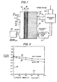
- Fig. 4 illustrates the performance of the fuel cell shown in Fig. 2 when operated at 65°C for both a methanol oxygen combination and a methanol/air combination.
- voltage of the fuel cell is illustrated along axis 32 and current density in mA/cm 2 is illustrated along axis 34.
- Curve 36 indicates performance of the methanol/oxygen combination while curve 38 illustrates performance of the methanol/air combination.
- the use of pure oxygen provides slightly better performance than air.
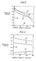
- Fig. 5 illustrates the effect of fuel concentration on cell performance.
- Fuel cell potential is illustrated along axis 40 while current density in mA/cm 2 is illustrated along axis 42.
- Curve 44 indicates performance for a 2.0 molar methanol solution at 150 degrees Fahrenheit (F).
- Curve 46 illustrates performance for a 0.5 molar methanol mixture at 140 degrees F.
- Curve 48 illustrates performance for a 4.0 M methanol mixture at 160 degrees F.
- the 2.0 M methanol mixture provides the best overall performance.
- Fig. 5 illustrates that the fuel cell can sustain current densities as high as 300 mA/cm 2 while maintaining reasonably high voltage.
- the 2.0 molar methanol mixture provides a voltage of over 0.4 volts at nearly 300 mA/cm 2 .
- the performance illustrated in Fig. 5 represents a significant improvement over the performance of previous organic fuel cells.
- Polarization behavior of the anode and cathode of the fuel cell are illustrated in Fig. 6 as a function of current density in mA/cm 2 , with voltage shown along axis 50 and current density along axis 52.
- Curve 54 illustrates polarization behavior for a 2.0 molar mixture at 150 degrees F.
- Curve 56 illustrates the polarization behavior for the fuel while curve 58 separately illustrates polarization behavior for the oxygen.
- the anode structure for liquid feed fuel cells must be quite different from that of conventional fuel cells.
- Conventional fuel cells employ gas diffusion type electrode structures that can provide gas, liquid and solid equilibrium.
- liquid feed type fuel cells require anode structures that are similar to batteries.
- the anode structures must be porous and must be capable of wetting the liquid fuel.
- the structures must have both electronic and ionic conductivity to effectively transport electrons to the anode current collector (carbon paper) and hydrogen/hydronium ions to the NafionTM electrolyte membrane.
- the anode structure must help achieve favorable gas evolving characteristics at the anode.
- Electrodes required for liquid feed type fuel cells can be fabricated specifically or conventional gas diffusion electrodes available commercially can be modified with suitable additives.
- the electrocatalyst layer and carbon fiber support of anode 14 are preferably impregnated with a hydrophilic proton-conducting polymer additive such as NafionTM.
- the additive is provided within the anode, in part, to permit efficient transport of protons and hydronium produced by the electro-oxidation reaction.
- the ionomeric additive also promotes uniform wetting of the electrode pores by the liquid fuel/water solution and provides for better utilization of the electrocatalyst. The kinetics of methanol electro-oxidation by reduced adsorption of anions is also improved. Furthermore, the use of the ionomeric additive helps achieve favorable gas evolving characteristics for the anode.
- the additive should be hydrophilic, proton-conducting, electrochemically stable and should not hinder the kinetics of oxidation of liquid fuel.
- NafionTM satisfies these criteria and is a preferred anode additive.
- Other hydrophilic proton-conducting additives which are expected to have the same effect as NafionTM are montmorrolinite clays, zeolites, alkoxycelluloses, cyclodextrins, and zirconium hydrogen phosphate.
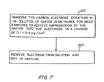
- Fig. 7 is a block diagram which illustrates the steps involved in impregnation of the anode with an ionomeric additive such as NafionTM.
- a carbon electrode structure is obtained or prepared.
- Commercially available high surface area carbon electrode structures which employ a mixture of high surface area electrocatalyst and TeflonTM binder applied on TorayTM carbon fiber paper may be used.
- An electro-catalytic electrode may also be prepared from high surface area catalyst particles and TorayTM paper, both available from E-Tek, Inc., using TFE-30TM, an emulsion of polytetrafluoroethylene.
- these structures can be prepared from the foregoing component materials, prefabricated structures may also be obtained directly from E-Tek in any desired dimension.
- the electrodes are impregnated with an ionomeric additive, such as NafionTM, by immersing the electrocatalyst particles in a solution containing 0.5 - 5% of the ionomeric additive (by appropriate dilution, with methanol or isopropanol, of solutions supplied by Aldrich Chemical Co., or Solution Technologies Inc.) for 5 - 10 minutes.
- the electrode is then removed, at step 304, from the solution and dried in air or vacuum at temperatures ranging from 20 - 60°C to volatilize any higher alcohol residues associated with the NafionTM solution.
- the impregnation steps 302 - 304 are repeated until the desired composition (which is in the range of 2 - 10% of the weight of the electrocatalyst) is achieved.
- a loading of 0.1 to 0.5 mg/cm 2 is exemplary.
- Electrode compositions with additive in excess of 10% may result in an increased internal resistance of the fuel cell and poor bonding with the solid polymer electrolyte membrane. Compositions with less than 2% of the additive do not typically result in improved electrode performance.
- the electrocatalyst particles are mixed in with a solution of NafionTM diluted to 1% with isopropanol. Then the solvent is allowed to evaporate until a thick mix is reached. The thick mix is then applied onto a TorayTM paper to form a thin layer of the electrocatalyst.
- a mixture of about 200 meter 2 /gram high surface area particles applied to the TorayTM paper is exemplary. Note here that the electrocatalyst layer so formed has only NafionTM and no TeflonTM. Electrodes so prepared are then dried in a vacuum at 60°C for 1 hour to remove higher alcohol residues, after which they are ready for use in liquid feed cells.
- Fig. 8 compares the performance of a NafionTM-impregnated electrode with a non-impregnated electrode as measured within a half cell similar to the cell of Fig. 10 (below) but containing a sulfuric acid electrolyte.
- Fig. 8 illustrates the polarization measurements in liquid formaldehyde fuel (1 molar) with sulfuric acid electrolyte (0.5 molar). The current density in mA/cm 2 is illustrated along axis 306 and the potential in volts along axis 308.
- Curve 310 is the galvanostatic polarization curve for a platinum-tin electrode that does not include NafionTM.
- Curve 312 is the galvanostatic polarization curve for a platinum-tin electrode not impregnated with NafionTM.
- a method for fabricating an electrode for use in a organic fuel cell will now be described in detail.
- the method is advantageously employed for fabricating a cathode for use in the liquid organic fuel cell described above.
- electrodes prepared by the method of Figs. 9 - 11 may alternatively be used in a variety of organic fuel cells.
- a carbon electrode structure is prepared by applying a mixture of high-surface-area carbon particles and a TeflonTM binder to a fiber-based carbon paper.
- the carbon particles have a surface area of 200 meters 2 /gram (m 2 /g).
- a suitable carbon particle substrate referred to Vulcan XC-72, is available from E-Tek Inc.
- the TeflonTM binder is preferably added to achieve a percentage, by weight, of 15%.
- the fiber based carbon paper is preferably TorayTM paper, also available from E-Tek Incorporated.
- the carbon structure may be prepared from the forgoing component materials. Alternatively, commercial prefabricated structures are available in 2 inch by 2 inch squares directly from E-Tek Inc.
- an electro-deposition bath is prepared by dissolving hydrogen hexachloropaltinate (IV) and potassium pentachloroaquoruthonium (III) within sulfuric acid.
- the resulting metal-ion concentration is within the range of 0.01- 0.05 M.
- the sulfuric acid has the concentration of 1 M.
- the forgoing compound is employed for obtaining platinum-ruthenium deposits on the carbon electrode structure.
- Alternative solutions may be employed. For example, to obtain platinum-tin deposits, a stannic chloride compound is dissolved in a sulfuric acid instead.
- the metallic ion salts are dissolved in the sulfuric acid primarily to prevent hydrolysis of the solution.
- the resulting solution is preferably de-aerated to prevent the formation of higher oxidation states.
- C-8 acid High purity perfluoroctanesulfonic acid (C-8 acid) is added to the bath at step 204.
- C-8 acid is preferably added to a concentration in a range of 0.1 - 1.0 grams/liters.
- C-8 acid is provided to facilitate complete wetting of the carbon particles.
- C-8 acid is electro-inactive and does not specifically adsorb at metal sites within the structure. Therefore, C-8 acid is innocuous to subsequent electro-deposition processes.
- the addition of C-8 acid has been found to be highly beneficial, and perhaps necessary for successful electro-deposition onto the electrodes.
- the carbon electrode structure resulting from step 200 is placed within the electro-deposition bath resulting from step 204.
- a platinum anode is also positioned within the bath.
- an alternate anode material may be employed for the deposition of other metal ions.
- a voltage is then applied between the carbon electrode structure and the platinum anode at step 208.
- the voltage is applied for about 5 to 10 minutes to achieve electro-deposition of platinum-ruthenium onto the carbon electrode to a loading of about 5 mg/cm 2 .
- a voltage of approximately -0.8V vs mercury sulfate reference electrode is applied.
- the electrode is removed, at step 210, and washed in deionized water.
- the electrode is washed at least three times in circulating de-ionized water for 15 minutes each time.
- the washing step is provided primarily to rid the surface of the carbon electrode of absorbed chloride and sulfate ions. The washing step has been found to be highly desirable, and perhaps necessary, for yielding an effective electrode for use in an organic fuel cell.
- Electrodes resulting from the fabrication method of step 206, have been found to have very uniform "cotton-ball"-shaped particles, with a significant amount of fine structure. Average particle size has been found to be on the order of 0.1 microns.
- FIG. 10 illustrates a three-electrode cell 212 which includes a single carbon-structure electrode 214, a pair of platinum counter-electrodes (or anodes) 216 and a reference electrode 218. All electrodes are positioned within a bath 220 formed of the aforementioned metallic/C-8 acid solution. Electrical contacts 222 and 224 are positioned on interior side surfaces of cell 212 above bath 220. A magnetic stirrer 226 is positioned within bath 220 to facilitate stirring and circulation of the bath. A circulating water jacket 228 is provided around cell 212 for use in regulating the temperature within the cell.
- the platinum anodes are positioned within fine glass frits 230, the glass frits being provided to isolate the anodes from the cathode to prevent the oxidation products of the anode from diffusing into the cathode.
- Reference electrode 214 is a mercury/mecurous-sulfate reference electrode.
- the reference electrode is provided to monitor and control the electrical potential of carbon electrode structure 214.
- both potentiostatic and galvanostatic control methods are employed.
- the composition of the alloy deposit is controlled by choosing a bath composition, summarized above, and by performing electrode-deposition at current densities well above any limiting current densities for the metal deposition. When selecting an appropriate bath composition it is important to normalize for the electrochemical equivalence of the metals within the composition.
- the quantity of charge passed from anode to cathode is detected and employed to monitor the quantity of material deposited.
- an amount of charge used in any hydrogen evolution reaction must be subtracted from each measurement of total charge.
- Adequate electro-deposition typically occurs within a period of five to ten minutes, depending upon the operating conditions and the catalyst loading desired.
- the monitoring equipment for use in monitoring and controlling the electrode potential are not illustrated in Fig. 10 as the function and operation of such devices are well known to those skilled in the art.
- Fig. 11 illustrates the performance of an exemplary electrode deposited using the method of Fig. 9 within the electro-deposition cell of Fig. 7.
- potential in volts versus NHE is provided along axis 240 whereas current density in mA/cm 2 is provided along axis 242.
- Curve 246 illustrates the galvanostatic polarization curve for a carbon-supported platinum-ruthenium alloy electrode prepared in accordance with the forgoing for a loading of 5 mg/cm 2 .
- Curve 246 illustrates galvanostatic polarization for an electrode having a 1 mg/cm 2 loading. In each case, the electrode was employed within a sulfuric acid electrolye in a half-cell.
- the fuel cell included an organic fuel composed of 1 molar methanol and 0.5 molar sulfuric acid, operated at 60°C. At the loading of 5 mg/cm 2, the electrode sustains a continuous current density of 100 mA/cm 2 at 0.45 volts versus NHE.
- Fig. 11 The results illustrated in Fig. 11 are exemplary of performance which may be achieved using an electrode fabricated in accordance with the method of Fig. 9. Further performance enhancement may be achieved with appropriate optimization of the electro-deposition conditions and the alloy composition. Hence, the particular conditions and concentrations described above are not necessarily optimal but merely represent a currently known best mode for fabricating electrodes.
- C-8 acid as an additive within an electro-deposition bath was described above. It has also been determined that C-8 acid may be advantageously applied as an additive within the fuel of a liquid feed fuel cell employing a sulfuric acid electrolyte. In particular, it has been found that straight chain C-8 acid, having the molecular formula C 8 F 17 SO 3 H, in concentrations from 0.001 to 0.1 M is an excellent wetting agent within a liquid feed fuel cell.
- Figs. 12 illustrates results of experiments which contrast the use of C-8 acid as an additive with fuel cells lacking the additive.
- Fig. 12 illustrates the results of half-cell experiments using a TeflonTM coated high-surface area carbon-supported platinum and platinum alloy electrode mounted within a sulfuric acid electrolyte. The results wee obtained using a half-cell similar to the cell illustrated in Fig. 10.
- Fig. 12 illustrates potential versus NHE along the vertical axis 400 and current density in mA/cm 2 along a horizontal axis 402. Four curves are provided illustrating polarization for a fuel containing no additive (curve 404), 0.0001 M additive (curve 406), 0.001 M additive (curve 408) and 0.01 M additive (curve 412).
- Fig. 12 demonstrates that the use of C8 acid as an additive in the concentration range 0.001 M or greater is beneficial to liquid fuel solutions when employing commercially available TeflonTM coated fuel cell electrodes, at least for fuel cells employing sulfuric acid as an electrolyte.
- the fuels are dimethoxymethane, trimethoxymethane, and trioxane.
- Figs. 13 - 15 illustrate the results of experiments conducted using dimethoxymethane (DMM) as a fuel for an organic direct liquid feed fuel cell.
- DMM dimethoxymethane
- the fuel cell may be of conventional design or may include one or more of the improvements described above.
- the DMM is electro-oxidized at the anode of the cell.
- the electro-oxidation of DMM involves a series of dissociative steps followed by surface reaction to form carbon dioxide and water.
- the electrochemical reaction is given by:
- Fig. 13 shows that increased concentration improves the kinetics of oxidation of DMM.
- the curves of Fig. 13 were measured in a half cell employing 0.5 M sulfuric acid as an electrolyte, along with 0.1 M C-8 acid. The measurements were conducted at room temperature.
- DMM can be oxidized at potentials considerably more negative than methanol. Also, temperature has been found to significantly influence the rates of oxidation. However, DMM has a low boiling point of 41°C. Hence, difficulties may arise in attempting to use DMM in a liquid feed fuel cell for temperatures higher than the boiling point.
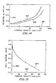
- Fig. 14 illustrates polarization for two different concentrations at two different temperatures.
- Current density is provided along axis 512 and polarization (in terms of potential v. NHE) is provided along axis 514.
- Curve 516 illustrates polarization for a 1 M concentration of DMM at room temperature.
- Curve 18 illustrates polarization for a 2 M concentration of DMM at 55°C.
- improved polarization is achieved using a higher concentration at a higher temperature.
- a comparison of curve 510 of Fig. 13 with curve 518 of Fig. 14 illustrates that an increase in temperature yields an improved polarization for the same concentration level. Hence, it is believed that an increase in temperature results in improved kinetics of electro-oxidation.
- Figs. 13 and 14 fuel cell experiments were also conducted to verify the effectiveness of DMM in a fuel cell.
- the direct oxidation of DMM in fuel cells was carried out in a liquid feed type fuel cell as illustrated above in Figs. 1 and 2.
- the fuel cell employed a proton conducting solid polymer membrane (NafionTM 117) as the electrolyte.
- the membrane electrode assembly consisted of a fuel oxidation electrode made of unsupported platinum-ruthenium catalyst layer (4 mg/cm 2 ) and gas-diffusion type unsupported platinum electrode (4 mg/cm 2 ) for the reduction of oxygen.
- the fuel cell used a 1 M solution of DMM on the fuel oxidation side and oxygen at 20 psi on the cathode.
- Methanol is considered a possible intermediate in the oxidation of DMM to carbon dioxide and water.
- the fuel cell system is compatible with methanol, the presence of methanol as an intermediate is not a concern since the methanol is also ultimately oxidized to carbon dioxide and water.
- Fig. 15 The current-voltage characteristics of a liquid feed direct oxidation fuel cell using DMM as a fuel is shown in Fig. 15.
- the fuel cell was operated at 37°C.
- current density in mA/cm 2 is provided along axis 520.
- Cell voltage in volts is provided along axis 522.
- Curve 524 illustrates cell voltage as a function of current density for a 1 M DMM solution described above.
- the cell voltages reached 0.25 V at 50 mA/cm 2 with DMM which is as high as that attained with methanol (not shown).
- the low boiling point of DMM also makes it a candidate for a gas-feed type operation.
- DMM is capable of being oxidized at very high rates. Therefore, it is believed that DMM is an excellent fuel for use in direct oxidation fuel cells. Also, DMM is a non-toxic, low-vapor pressure liquid, permitting easy handling. In addition DMM can be synthesized from natural gas (methane) by conventional techniques.
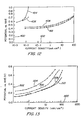
- Figs. 16 - 18 illustrate the results of experiments conducted using trimethoxymethane (TMM) as a fuel for an organic direct liquid feed fuel cell.
- TMM trimethoxymethane
- DMM trimethoxymethane
- TMM is mixed with water to a concentration in the range of about 0.1 to 2 M and fed into a fuel cell. Other concentrations may also be effective.
- the fuel cell may be of conventional design or may include one or more of the improvements described above.
- the TMM is electro-oxidized at the anode of the cell.
- the electrochemical oxidation of TMM is represented by the following action:
- Fig. 16 provides galvanostatic polarization curves for several different concentrations of TMM for the above-mentioned Pt-Sn electrodes.
- the Pt-Sn electrodes were of the gas-diffusion type and consisted of 0.5 mg/cm2 of total metal supported on Vulcan XC-72 obtained from Etek, Inc., Framingham, MA.
- current density in mA/cm 2 is provided along axis 600 and polarization (in terms of potential v. NHE) is provided along axis 602.
- Curves 604, 606, 608 and 610, respectively, illustrate polarization for TMM concentrations of 0.1 M, 0.5 M, 1 M and 2 M TMM.
- Fig. 16 shows that improved polarization is achieved at higher concentration levels. All measurements shown in Fig. 16 were obtained at room temperature.
- Fig. 17 illustrates polarization at two different concentrations and at two different temperatures.
- current density in mA/cm 2 is provided along axis 612 and polarization (in potential v. NHE) is provided along axis 614.
- Curve 616 illustrates polarization for a 1 M TMM concentration at room temperature whereas curve 618 illustrates polarization for a 2 M concentration of TMM at 55°C.
- the curves of Fig. 17 were obtained using a Pt-Sn electrode in a 0.5 M sulfuric electrolyte including 0.01 M C-8 acid.
- Fig. 18 The current-voltage characteristics of the above-described liquid feed direct oxidation fuel cell is shown in Fig. 18 for both TMM and methanol.
- Current density in mA/cm 2 is provided along axis 620 and cell voltage is provided along axis 622.
- Curve 624 shows cell voltage as a function of current density for a 1 M concentration of TMM.
- Curve 626 illustrates the same for a 1 M concentration of methanol.
- the measurements shown in Fig. 18 were obtained at 65°C. Although not shown, at 90°C, cell voltages can reach 0.52 V at 300 mA/cm 2 with TMM which is higher than that attained with methanol.
- TMM like DMM
- TMM is capable of being oxidized at very high rates.
- TMM is a non-toxic, low-vapor pressure liquid, permitting easy handling, and can be synthesized from natural gas (methane) by conventional methods.
- Trioxane as a fuel for a liquid feed fuel cell
- Figs. 19 - 21 illustrate the results of experiments conducted using trioxane as a fuel for an organic direct liquid feed fuel cell.
- trioxane is mixed with water to a concentration in the range of about 0.1 to 2 M and fed into a fuel cell. Other concentrations may also be effective.
- the fuel cell may be of conventional design or may include one or more of the improvements described above.
- the trioxane is electro-oxidized at the anode of the cell.
- the electrochemical oxidation of trioxane is represented by the following action:
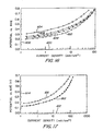
- Fig. 19 provides galvanostatic polarization curves for several different concentrations of trioxane for the above-mentioned Pt-Sn electrodes.
- the Pt-Sn electrodes were of the gas-diffusion type and consisted of 0.5 mg/cm2 of the total noble metal supported on Vulcan XC-72 obtained from Etek, Inc., Framingham, MA.
- current density in mA/cm 2 is provided along axis 700 and polarization (in terms of potential v. NHE) is provided along axis 702.
- Curves 704, 706, 708 and 710, respectively, illustrate polarization for trioxane at concentrations of 0.1 M, 0.5 M, 1 M and 2 M.
- Fig. 19 shows that improved polarization is achieved at higher concentration levels. All measurements shown in Fig. 19 were obtained at 55°C.
- trioxane For trioxane, increasing fuel concentration results in an increased rate of oxidation. Also, as can be seen from Fig. 19, current densities as high as 100 mA/cm2 are achieved at potentials of 0.4 V vs. NHE. This performance is comparable to the performances achieved with formaldehyde. Although not shown, cyclic voltammetry studies have determined that the mechanism of oxidation of trioxane does not involve a breakdown to formaldehyde before electro-oxidation.
- Fig. 20 illustrates polarization at four different electrolyte concentrations and at two different temperatures.
- current density in mA/cm 2 is provided along axis 712 and polarization (in potential v. NHE ) is provided along axis 714.
- Curve 716 illustrates polarization for a 0.5 M electrolyte concentration at room temperature.
- Curve 718 illustrates polarization for a 0.5 M electrolyte concentration at 65°C.
- Curve 720 illustrates polarization for a 1 M electrolyte concentration at 65°C.
- curve 722 illustrates polarization for a 2 M electrolyte concentration at 65°C. For all of curves 716 - 722, the trioxane concentration was 2 M.
- Fig. 20 The curves of Fig. 20 were obtained using a Pt-Sn electrode in a sulfuric acid electrolyte including 0.01 M C-8 acid. As can be seen, improved polarization is achieved using a higher electrolyte concentration at a higher temperature. Therefore it was projected that very high rates of electro-oxidation are expected with NafionTM as an electrolyte since NafionTM exhibits an acidity equivalent of 10 M sulfuric acid.
- Fig. 21 The current-voltage characteristics of the above-described liquid feed direct oxidation fuel cell is shown in Fig. 21 for trioxane.
- Current density in mA/cm 2 is provided along axis 724 and cell voltage is provided along axis 726.
- Curve 728 shows cell voltage as a function of current density for a 1 M concentration of trioxane.
- the measurements shown in Fig. 21 were obtained at 60°C.
- the performance illustrated in Fig. 21 may be improved considerably using platinum-tin electrodes, rather than Pt-Ru electrodes.
- a measurement of crossover, not shown, in the trioxane/oxygen fuel cell suggests that a rate of crossover is at least 5 times lower than that in methanol fuel cells.
- the decreased rates of crossover are extremely desirable since, as described above, crossover affects the efficiency and performance of fuel cells.
- trioxane like DMM and TMM, is capable of being oxidized at very high rates.
Applications Claiming Priority (4)
| Application Number | Priority Date | Filing Date | Title |
|---|---|---|---|
| EP95900379A EP0755576B1 (fr) | 1994-10-18 | 1994-10-18 | Pile a combustible organique, mise en oeuvre de cette pile et fabrication d'une electrode qui lui est destinee |
| CA002203153A CA2203153A1 (fr) | 1994-10-18 | 1994-10-18 | Pile a combustible organique, mise en oeuvre de cette pile et fabrication d'une electrode qui lui est destinee |
| PCT/US1994/011911 WO1996012317A1 (fr) | 1994-10-18 | 1994-10-18 | Pile a combustible organique, mise en oeuvre de cette pile et fabrication d'une electrode qui lui est destinee |
| IL11586795A IL115867A (en) | 1994-10-18 | 1995-11-03 | Organic fuel cell methods and apparatus |
Related Parent Applications (1)
| Application Number | Title | Priority Date | Filing Date |
|---|---|---|---|
| EP95900379.9 Division | 1996-04-25 |
Publications (2)
| Publication Number | Publication Date |
|---|---|
| EP1519432A2 true EP1519432A2 (fr) | 2005-03-30 |
| EP1519432A3 EP1519432A3 (fr) | 2005-07-13 |
Family
ID=27170342
Family Applications (12)
| Application Number | Title | Priority Date | Filing Date |
|---|---|---|---|
| EP04019948A Withdrawn EP1507304A1 (fr) | 1994-10-18 | 1994-10-18 | Système à piles à combustible et son procédé d'opération |
| EP04019945A Withdrawn EP1498975A3 (fr) | 1994-10-18 | 1994-10-18 | Cellule à combustible organique avec migration de réactifs réduite |
| EP04019949A Withdrawn EP1519432A3 (fr) | 1994-10-18 | 1994-10-18 | Electrode |
| EP04019944A Withdrawn EP1498973A1 (fr) | 1994-10-18 | 1994-10-18 | Cellule de combustible organique avec un additif d'électrocatalyseur |
| EP95900379A Revoked EP0755576B1 (fr) | 1994-10-18 | 1994-10-18 | Pile a combustible organique, mise en oeuvre de cette pile et fabrication d'une electrode qui lui est destinee |
| EP04019943A Withdrawn EP1507303A1 (fr) | 1994-10-18 | 1994-10-18 | Cellule de combustible organique à membranes améliorées |
| EP04019942A Withdrawn EP1498972A3 (fr) | 1994-10-18 | 1994-10-18 | Cellule de combustible organique avec un système de récupération d'eau |
| EP02025417A Withdrawn EP1291950A3 (fr) | 1994-10-18 | 1994-10-18 | Pile à combustible organique et mise en oeuvre de cette pile |
| EP04019940A Withdrawn EP1489674A3 (fr) | 1994-10-18 | 1994-10-18 | Pile à combustible organique avec un distributeur d'air |
| EP04019947A Withdrawn EP1508931A1 (fr) | 1994-10-18 | 1994-10-18 | Cellule à combustible organique avec anode améliorée |
| EP04019941A Withdrawn EP1489676A3 (fr) | 1994-10-18 | 1994-10-18 | Cellule de combustible organique avec séparateur de gaz |
| EP04019946A Withdrawn EP1508930A1 (fr) | 1994-10-18 | 1994-10-18 | Cellule de combistuble organique à membrane échangeuse d'ions |
Family Applications Before (2)
| Application Number | Title | Priority Date | Filing Date |
|---|---|---|---|
| EP04019948A Withdrawn EP1507304A1 (fr) | 1994-10-18 | 1994-10-18 | Système à piles à combustible et son procédé d'opération |
| EP04019945A Withdrawn EP1498975A3 (fr) | 1994-10-18 | 1994-10-18 | Cellule à combustible organique avec migration de réactifs réduite |
Family Applications After (9)
| Application Number | Title | Priority Date | Filing Date |
|---|---|---|---|
| EP04019944A Withdrawn EP1498973A1 (fr) | 1994-10-18 | 1994-10-18 | Cellule de combustible organique avec un additif d'électrocatalyseur |
| EP95900379A Revoked EP0755576B1 (fr) | 1994-10-18 | 1994-10-18 | Pile a combustible organique, mise en oeuvre de cette pile et fabrication d'une electrode qui lui est destinee |
| EP04019943A Withdrawn EP1507303A1 (fr) | 1994-10-18 | 1994-10-18 | Cellule de combustible organique à membranes améliorées |
| EP04019942A Withdrawn EP1498972A3 (fr) | 1994-10-18 | 1994-10-18 | Cellule de combustible organique avec un système de récupération d'eau |
| EP02025417A Withdrawn EP1291950A3 (fr) | 1994-10-18 | 1994-10-18 | Pile à combustible organique et mise en oeuvre de cette pile |
| EP04019940A Withdrawn EP1489674A3 (fr) | 1994-10-18 | 1994-10-18 | Pile à combustible organique avec un distributeur d'air |
| EP04019947A Withdrawn EP1508931A1 (fr) | 1994-10-18 | 1994-10-18 | Cellule à combustible organique avec anode améliorée |
| EP04019941A Withdrawn EP1489676A3 (fr) | 1994-10-18 | 1994-10-18 | Cellule de combustible organique avec séparateur de gaz |
| EP04019946A Withdrawn EP1508930A1 (fr) | 1994-10-18 | 1994-10-18 | Cellule de combistuble organique à membrane échangeuse d'ions |
Country Status (10)
| Country | Link |
|---|---|
| EP (12) | EP1507304A1 (fr) |
| JP (8) | JP3795920B2 (fr) |
| KR (4) | KR100372029B1 (fr) |
| CN (2) | CN1638176A (fr) |
| AU (1) | AU716164B2 (fr) |
| BR (1) | BR9408623A (fr) |
| CA (1) | CA2203153A1 (fr) |
| DE (2) | DE69435082T2 (fr) |
| IL (2) | IL127662A (fr) |
| WO (1) | WO1996012317A1 (fr) |
Families Citing this family (64)
| Publication number | Priority date | Publication date | Assignee | Title |
|---|---|---|---|---|
| US5672438A (en) * | 1995-10-10 | 1997-09-30 | E. I. Du Pont De Nemours And Company | Membrane and electrode assembly employing exclusion membrane for direct methanol fuel cell |
| US5795496A (en) * | 1995-11-22 | 1998-08-18 | California Institute Of Technology | Polymer material for electrolytic membranes in fuel cells |
| WO1997050141A1 (fr) * | 1996-06-26 | 1997-12-31 | Siemens Aktiengesellschaft | Anode pour une pile a combustible directe au methanol |
| US6444343B1 (en) | 1996-11-18 | 2002-09-03 | University Of Southern California | Polymer electrolyte membranes for use in fuel cells |
| US5981097A (en) * | 1996-12-23 | 1999-11-09 | E.I. Du Pont De Nemours And Company | Multiple layer membranes for fuel cells employing direct feed fuels |
| DE19701560C2 (de) * | 1997-01-17 | 1998-12-24 | Dbb Fuel Cell Engines Gmbh | Brennstoffzellensystem |
| US5904740A (en) * | 1997-06-03 | 1999-05-18 | Motorola, Inc. | Fuel for liquid feed fuel cells |
| EP1060535B1 (fr) * | 1998-02-25 | 2002-05-02 | Ballard Power Systems Inc. | Piles a combustible utilisant directement l'ether dimetylique |
| US6548202B2 (en) | 1998-03-06 | 2003-04-15 | Ballard Power System, Inc. | Carbon-supported catalysts for fuel cells |
| US6074773A (en) * | 1998-03-06 | 2000-06-13 | Ballard Power Systems Inc. | Impregnation of microporous electrocatalyst particles for improving performance in an electrochemical fuel cell |
| US6500571B2 (en) | 1998-08-19 | 2002-12-31 | Powerzyme, Inc. | Enzymatic fuel cell |
| US6153323A (en) | 1998-10-16 | 2000-11-28 | Ballard Power Systems Inc. | Electrode treatment method for improving performance in liquid feed fuel cells |
| DE69902557T2 (de) * | 1998-10-16 | 2003-01-09 | Ballard Power Systems | Imprägnierung mit ionomeren von elektrodensubstraten zur leistungsverbesserung von brennstoffzellen |
| US6263745B1 (en) | 1999-12-03 | 2001-07-24 | Xy, Inc. | Flow cytometer nozzle and flow cytometer sample handling methods |
| CA2387674C (fr) * | 2000-08-11 | 2010-04-27 | Honda Giken Kogyo Kabushiki Kaisha | Pile a combustible polymere solide |
| KR100407793B1 (ko) * | 2001-09-04 | 2003-12-01 | 한국과학기술연구원 | 분리능이 있는 수소 이온 교환 복합막, 복합 용액, 그제조방법 및 이를 포함하는 연료전지 |
| JP2003242989A (ja) * | 2002-02-13 | 2003-08-29 | Hitachi Maxell Ltd | 燃料電池 |
| WO2003088402A1 (fr) * | 2002-04-04 | 2003-10-23 | The Board Of Trustees Of The University Of Illinois | Piles a combustible et catalyseurs pour piles a combustible |
| US7144476B2 (en) * | 2002-04-12 | 2006-12-05 | Sgl Carbon Ag | Carbon fiber electrode substrate for electrochemical cells |
| WO2003100897A1 (fr) * | 2002-05-28 | 2003-12-04 | Gs Yuasa Corporation | Systeme de piles a combustible du type combustible liquide et procede de mise en oeuvre d'un tel systeme |
| JP3748434B2 (ja) | 2002-06-12 | 2006-02-22 | 株式会社東芝 | 直接型メタノール燃料電池システム及び燃料カートリッジ |
| JP2006080092A (ja) * | 2002-06-12 | 2006-03-23 | Toshiba Corp | 直接型メタノール燃料電池システム、燃料カートリッジ及び燃料カートリッジ用メモリ |
| JP3744474B2 (ja) * | 2002-06-28 | 2006-02-08 | 日本電気株式会社 | 固体電解質型燃料電池用燃料、固体電解質型燃料電池およびその使用方法 |
| EP1548863A1 (fr) | 2002-07-25 | 2005-06-29 | Matsushita Electric Industrial Co., Ltd. | Membrane electrolytique, ensemble d'electrodes comportant une telle membrane, et pile a combustible |
| US6864001B2 (en) | 2002-09-13 | 2005-03-08 | Ballard Power Systems Inc. | Tetramethyl orthocarbonate fuel cells and systems and methods related thereto |
| CN1300886C (zh) | 2002-09-30 | 2007-02-14 | 株式会社杰士汤浅 | 液体燃料直接供给型燃料电池系统及其运行控制方法和运行控制装置 |
| CN1310360C (zh) | 2002-11-28 | 2007-04-11 | 株式会社东芝 | 直接型燃料电池发电装置 |
| JP4625627B2 (ja) * | 2002-11-28 | 2011-02-02 | 株式会社東芝 | 直接型燃料電池発電装置 |
| WO2004070865A1 (fr) | 2003-02-10 | 2004-08-19 | Matsushita Electric Industrial Co. Ltd. | Systeme de pile a combustible |
| KR20050111625A (ko) * | 2003-03-31 | 2005-11-25 | 가부시키가이샤 지에스 유아사 코포레이션 | 직접 메탄올형 연료전지 및 그 연료극의 용출방지방법,품질관리방법, 운전방법 |
| US20070020497A1 (en) * | 2003-05-07 | 2007-01-25 | Gs Yuasa Corporation | Direct fuel cell system |
| JP2005100886A (ja) * | 2003-09-26 | 2005-04-14 | Matsushita Electric Ind Co Ltd | 燃料電池システム、及び燃料電池への燃料供給方法 |
| JP4843898B2 (ja) * | 2003-10-08 | 2011-12-21 | 株式会社日立製作所 | 燃料電池装置及びその制御方法 |
| JP3889002B2 (ja) | 2004-01-07 | 2007-03-07 | 松下電器産業株式会社 | 燃料電池 |
| JP4664607B2 (ja) * | 2004-02-27 | 2011-04-06 | 株式会社東芝 | 燃料電池ユニット、情報処理装置、燃料電池ユニットの制御方法および情報処理装置の電力供給方法 |
| JP2005267976A (ja) * | 2004-03-17 | 2005-09-29 | T Rad Co Ltd | 熱交換器 |
| JP4478009B2 (ja) * | 2004-03-17 | 2010-06-09 | 日東電工株式会社 | 燃料電池 |
| US7976972B2 (en) | 2004-06-14 | 2011-07-12 | Panasonic Corporation | Method of preserving polymer electrolyte fuel cell stack and preservation assembly of polymer electrolyte fuel cell stack |
| WO2006004120A1 (fr) * | 2004-07-06 | 2006-01-12 | Matsushita Electric Industrial Co., Ltd. | Procédé de fabrication d’électrode de diffusion de gaz et de pile à combustible électrolytique polymère, et électrode de diffusion de gaz et pile à combustible électrolytique polymère |
| CN100369305C (zh) * | 2004-12-30 | 2008-02-13 | 比亚迪股份有限公司 | 一种燃料电池 |
| KR100626089B1 (ko) * | 2004-12-31 | 2006-09-21 | 삼성에스디아이 주식회사 | 액체연료 혼합장치 및 이를 구비한 직접액체연료전지 시스템 |
| JP2006202598A (ja) * | 2005-01-20 | 2006-08-03 | Toray Ind Inc | 燃料電池用電極および燃料電池 |
| TW200722741A (en) * | 2005-12-09 | 2007-06-16 | Antig Tech Co Ltd | Method of calculating fuel concentration of liquid fuel cell |
| US20070202369A1 (en) * | 2006-02-27 | 2007-08-30 | Korea Institute Of Science And Technology | Direct formic acid fuel cell performing real time measurement and control of concentration of formic acid and operation method thereof |
| KR101252839B1 (ko) | 2006-03-03 | 2013-04-09 | 삼성에스디아이 주식회사 | 회수장치를 채용한 연료전지 |
| JP5151061B2 (ja) * | 2006-04-14 | 2013-02-27 | トヨタ自動車株式会社 | 燃料電池 |
| DE102006037148A1 (de) * | 2006-08-09 | 2008-02-14 | Forschungszentrum Jülich GmbH | Direkt-Alkohol-Brennstoffzellenstapel mit einem Kohlendioxidabscheider |
| JP5252887B2 (ja) * | 2006-11-16 | 2013-07-31 | ヤマハ発動機株式会社 | 燃料電池システムおよびその制御方法 |
| KR100786579B1 (ko) | 2006-12-20 | 2007-12-21 | 한국화학연구원 | 스텝 전위법을 이용한 금속 촉매 전극의 제조 방법 |
| JP5122837B2 (ja) * | 2007-03-01 | 2013-01-16 | シャープ株式会社 | 燃料電池および電子機器 |
| JP2008311166A (ja) | 2007-06-18 | 2008-12-25 | Panasonic Corp | 燃料電池システム |
| US9065095B2 (en) | 2011-01-05 | 2015-06-23 | Ini Power Systems, Inc. | Method and apparatus for enhancing power density of direct liquid fuel cells |
| IN2014DN03036A (fr) * | 2011-12-20 | 2015-05-08 | United Technologies Corp | |
| JP2013134981A (ja) * | 2011-12-27 | 2013-07-08 | Daihatsu Motor Co Ltd | 燃料電池システム |
| WO2015146454A1 (fr) * | 2014-03-28 | 2015-10-01 | 国立大学法人山梨大学 | Catalyseur d'électrode et procédé de production de catalyseur d'électrode |
| KR102575409B1 (ko) * | 2017-12-28 | 2023-09-05 | 현대자동차주식회사 | 연료전지용 전해질막의 제조방법 및 이를 포함하는 막-전극 접합체의 제조방법 |
| US20190267636A1 (en) * | 2018-02-27 | 2019-08-29 | GM Global Technology Operations LLC | Enhancing catalyst activity of a pem fuel cell electrode with an ionic liquid additive |
| JP7127603B2 (ja) * | 2019-04-15 | 2022-08-30 | トヨタ自動車株式会社 | 燃料電池用電極触媒層の製造方法 |
| CN110277579A (zh) * | 2019-06-17 | 2019-09-24 | 深圳市通用氢能科技有限公司 | 一种燃料电池用膜电极结构、燃料电池膜电极的制备方法及质子交换膜燃料电池系统 |
| CN110247062B (zh) * | 2019-06-17 | 2021-07-27 | 深圳市通用氢能科技有限公司 | 一种燃料电池膜电极的制备方法 |
| CN111425283A (zh) * | 2020-04-14 | 2020-07-17 | 苏州钧峰新能源科技有限公司 | 一种甲醇燃料发电系统的尾气净化装置 |
| CN111900420A (zh) * | 2020-07-06 | 2020-11-06 | 浙江锋源氢能科技有限公司 | 一种阳极催化剂浆料、阳极催化剂层、膜电极及燃料电池 |
| JP2022086444A (ja) * | 2020-11-30 | 2022-06-09 | トヨタ自動車株式会社 | 電池パック |
| CN114824642B (zh) * | 2021-03-30 | 2024-03-12 | 宁德新能源科技有限公司 | 电化学装置和电子装置 |
Citations (12)
| Publication number | Priority date | Publication date | Assignee | Title |
|---|---|---|---|---|
| GB1160084A (en) * | 1965-09-30 | 1969-07-30 | Leesona Corp | Improvements in or relating to Fluorocarbon Polymeric Matrices |
| US3532556A (en) * | 1966-09-01 | 1970-10-06 | Matthey Bishop Inc | Process for forming platinum coated electrode |
| US4262063A (en) * | 1978-05-26 | 1981-04-14 | Hitachi, Ltd. | Fuel cell using electrolyte-soluble fuels |
| US4490219A (en) * | 1982-10-07 | 1984-12-25 | International Business Machines Corporation | Method of manufacture employing electrochemically dispersed platinum catalysts deposited on a substrate |
| US4541905A (en) * | 1983-12-13 | 1985-09-17 | The Ohio State University Research Foundation | Electrodes for use in electrocatalytic processes |
| US4931168A (en) * | 1986-03-07 | 1990-06-05 | Masahiro Watanabe | Gas permeable electrode |
| US5162166A (en) * | 1991-07-19 | 1992-11-10 | Kerr-Mcgee Corporation | Devices providing electrical energy from fuel/oxygen mixtures |
| DE4116359A1 (de) * | 1991-05-18 | 1992-11-19 | Varta Batterie | Verfahren zur herstellung einer gaserzeugenden elektrochemischen zelle |
| DE4243600A1 (en) * | 1991-12-25 | 1993-07-01 | Equos Research Kabushiki Kaish | Electrolyte membrane for fuel cells esp. for cars - comprises three=dimensional structure of crosslinked polymer, pref. PVA, contg. uniformly distributed polyelectrolyte |
| US5330860A (en) * | 1993-04-26 | 1994-07-19 | E. I. Du Pont De Nemours And Company | Membrane and electrode structure |
| WO1994016811A1 (fr) * | 1993-01-27 | 1994-08-04 | Syracuse University | Charbons actifs transformes au niveau de la molecule |
| US5364711A (en) * | 1992-04-01 | 1994-11-15 | Kabushiki Kaisha Toshiba | Fuel cell |
Family Cites Families (49)
| Publication number | Priority date | Publication date | Assignee | Title |
|---|---|---|---|---|
| DE1255231B (de) * | 1956-12-08 | 1967-11-30 | Bayer Ag | Verfahren zum Fuellen von Leder |
| US3143440A (en) * | 1960-08-04 | 1964-08-04 | Hunger Herbert | Fuel cell |
| US3013098A (en) * | 1960-10-03 | 1961-12-12 | Herbert F Hunger | Fuel cell with cation exchange resin membrane as electrolyte |
| US3113049A (en) * | 1961-01-03 | 1963-12-03 | Exxon Research Engineering Co | Direct production of electrical energy from liquid fuels |
| US3368922A (en) * | 1962-10-26 | 1968-02-13 | Monsanto Res Corp | Polyelectrolyte membrane comprising a copolymer including acrylonitrile and fuel cell with same |
| FR1436154A (fr) * | 1964-04-01 | 1966-04-22 | Thomson Houston Comp Francaise | Perfectionnements à des piles à combustibles |
| US3457113A (en) * | 1965-03-01 | 1969-07-22 | Monsanto Res Corp | Laminar electrode including hydrophobic and hydrophilic layfrs; method of making; fuel cell therewith; and method of using fuel cell |
| US3992223A (en) * | 1967-01-04 | 1976-11-16 | Siemens Aktiengesellschaft | Method and apparatus for removing reaction water from fuel cells |
| FR1522309A (fr) * | 1967-02-24 | 1968-04-26 | Alsthom Cgee | Pile à combustible à électrolyte basique à décarbonatation continue automatique |
| DE1771369B1 (de) * | 1968-05-14 | 1972-05-31 | Varta Ag | Verfahren zur abscheidung von karbonationen aus alkalischen elektrolyten von brennstoffelementen |
| US3811817A (en) * | 1973-02-20 | 1974-05-21 | Bell Co Inc | Lamp for producing colored flame |
| US4160856A (en) * | 1974-01-25 | 1979-07-10 | Societe Generale De Constructions Electriques Et Mecaniques"Alsthom Et Cie | Novel fuel cell containing novel means for removal of carbonates |
| JPS5476443A (en) * | 1977-11-30 | 1979-06-19 | Dainippon Ink & Chem Inc | Fluorine type surfactant mixture suitable for preventing planting mist |
| JPS5768142A (en) * | 1980-10-14 | 1982-04-26 | Hitachi Ltd | Electrode catalyst for fuel cell and its production |
| US4390603A (en) * | 1981-06-30 | 1983-06-28 | Hitachi, Ltd. | Methanol fuel cell |
| JPS5828175A (ja) * | 1981-08-12 | 1983-02-19 | Hitachi Ltd | 燃料電池 |
| US4612261A (en) * | 1981-08-21 | 1986-09-16 | Hitachi, Ltd. | Fuel cell battery using acidic electrolyte |
| US4420544A (en) * | 1981-10-02 | 1983-12-13 | California Institute Of Technology | High performance methanol-oxygen fuel cell with hollow fiber electrode |
| JPS58165266A (ja) * | 1982-03-26 | 1983-09-30 | Hitachi Ltd | 燃料電池 |
| JPS58165274A (ja) * | 1982-03-26 | 1983-09-30 | Hitachi Ltd | 燃料電池 |
| JPS58186170A (ja) * | 1982-04-23 | 1983-10-31 | Hitachi Ltd | 液体燃料電池 |
| JPS5923473A (ja) * | 1982-07-30 | 1984-02-06 | Hitachi Ltd | 燃料電池及び燃料電池用電解質構造体 |
| JPS59209277A (ja) * | 1983-05-13 | 1984-11-27 | Hitachi Ltd | 燃料電池 |
| JPS6023977A (ja) * | 1983-07-20 | 1985-02-06 | Hitachi Ltd | 燃料電池 |
| JPS6062064A (ja) * | 1983-09-14 | 1985-04-10 | Hitachi Ltd | 液体燃料電池 |
| JPS60165062A (ja) * | 1984-02-07 | 1985-08-28 | Hitachi Ltd | 燃料電池 |
| JPS60189174A (ja) * | 1984-03-07 | 1985-09-26 | Hitachi Ltd | 燃料電池 |
| US4629664A (en) * | 1984-10-31 | 1986-12-16 | Hitachi, Ltd. | Liquid fuel cell |
| JPH0622144B2 (ja) * | 1986-04-18 | 1994-03-23 | 三菱電機株式会社 | 燃料電池 |
| DE3618840A1 (de) * | 1986-06-04 | 1987-12-10 | Basf Ag | Methanol/luft-brennstoffzellen |
| JPS6366860A (ja) * | 1986-09-09 | 1988-03-25 | Hitachi Ltd | メタノ−ル燃料電池 |
| JPS6376264A (ja) * | 1986-09-18 | 1988-04-06 | Hitachi Maxell Ltd | 常温型酸性メタノ−ル燃料電池 |
| US4829017A (en) * | 1986-09-25 | 1989-05-09 | Texas Instruments Incorporated | Method for lubricating a high capacity dram cell |
| US4876115A (en) * | 1987-01-30 | 1989-10-24 | United States Department Of Energy | Electrode assembly for use in a solid polymer electrolyte fuel cell |
| US4795683A (en) * | 1987-07-23 | 1989-01-03 | United Technologies Corporation | High power density evaporatively cooled ion exchange membrane fuel cell |
| US4824736A (en) * | 1987-09-23 | 1989-04-25 | Aristech Chemical Corporation | Gasoline tank of tin-free (electroplate chrome-chrome oxide coated) steel coated with a maleic anhydride modified polypropylene |
| US4865925A (en) * | 1987-12-14 | 1989-09-12 | Hughes Aircraft Company | Gas permeable electrode for electrochemical system |
| JP2939978B2 (ja) * | 1988-11-30 | 1999-08-25 | 松下電器産業株式会社 | アルコール燃料電池及びその作動方法 |
| JPH02223984A (ja) * | 1989-02-27 | 1990-09-06 | Nec Corp | 栄養価計算装置 |
| JPH03201370A (ja) * | 1989-12-27 | 1991-09-03 | Sekiyu Sangyo Katsuseika Center | 燃料電池発電プロセスの改良法 |
| US5132193A (en) * | 1990-08-08 | 1992-07-21 | Physical Sciences, Inc. | Generation of electricity with fuel cell using alcohol fuel |
| JPH04162365A (ja) * | 1990-10-25 | 1992-06-05 | Tanaka Kikinzoku Kogyo Kk | 燃料電池用電極の作製法 |
| JPH04229958A (ja) * | 1990-12-27 | 1992-08-19 | Aisin Aw Co Ltd | 液体燃料電池の気液分離器 |
| US5318863A (en) * | 1991-12-17 | 1994-06-07 | Bcs Technology, Inc. | Near ambient, unhumidified solid polymer fuel cell |
| JPH06188008A (ja) * | 1992-04-01 | 1994-07-08 | Toshiba Corp | 燃料電池 |
| JP3271801B2 (ja) * | 1992-09-22 | 2002-04-08 | 田中貴金属工業株式会社 | 高分子固体電解質型燃料電池、該燃料電池の加湿方法、及び製造方法 |
| EP0596366B1 (fr) * | 1992-11-05 | 1997-04-23 | Siemens Aktiengesellschaft | Procédé et dispositif pour évacuation de l'eau et des gaz inertes dans une batterie de piles à combustible |
| JPH06251779A (ja) * | 1993-02-24 | 1994-09-09 | Asahi Chem Ind Co Ltd | 燃料電池用固体高分子電解質層と電極との接合体の作成方法 |
| US5599638A (en) * | 1993-10-12 | 1997-02-04 | California Institute Of Technology | Aqueous liquid feed organic fuel cell using solid polymer electrolyte membrane |
-
1994
- 1994-10-18 BR BR9408623A patent/BR9408623A/pt not_active IP Right Cessation
- 1994-10-18 EP EP04019948A patent/EP1507304A1/fr not_active Withdrawn
- 1994-10-18 KR KR1019970702571A patent/KR100372029B1/ko not_active IP Right Cessation
- 1994-10-18 EP EP04019945A patent/EP1498975A3/fr not_active Withdrawn
- 1994-10-18 EP EP04019949A patent/EP1519432A3/fr not_active Withdrawn
- 1994-10-18 EP EP04019944A patent/EP1498973A1/fr not_active Withdrawn
- 1994-10-18 CN CNA2005100041553A patent/CN1638176A/zh active Pending
- 1994-10-18 EP EP95900379A patent/EP0755576B1/fr not_active Revoked
- 1994-10-18 EP EP04019943A patent/EP1507303A1/fr not_active Withdrawn
- 1994-10-18 EP EP04019942A patent/EP1498972A3/fr not_active Withdrawn
- 1994-10-18 AU AU81219/94A patent/AU716164B2/en not_active Ceased
- 1994-10-18 JP JP51318696A patent/JP3795920B2/ja not_active Expired - Lifetime
- 1994-10-18 EP EP02025417A patent/EP1291950A3/fr not_active Withdrawn
- 1994-10-18 WO PCT/US1994/011911 patent/WO1996012317A1/fr active IP Right Grant
- 1994-10-18 EP EP04019940A patent/EP1489674A3/fr not_active Withdrawn
- 1994-10-18 EP EP04019947A patent/EP1508931A1/fr not_active Withdrawn
- 1994-10-18 EP EP04019941A patent/EP1489676A3/fr not_active Withdrawn
- 1994-10-18 CA CA002203153A patent/CA2203153A1/fr not_active Abandoned
- 1994-10-18 DE DE69435082T patent/DE69435082T2/de not_active Expired - Lifetime
- 1994-10-18 DE DE0755576T patent/DE755576T1/de active Pending
- 1994-10-18 EP EP04019946A patent/EP1508930A1/fr not_active Withdrawn
-
1995
- 1995-11-03 IL IL12766295A patent/IL127662A/xx active IP Right Grant
- 1995-11-03 IL IL11586795A patent/IL115867A/xx active IP Right Grant
-
2001
- 2001-10-10 CN CN01135489A patent/CN1411087A/zh active Pending
-
2002
- 2002-05-28 KR KR1020020029700A patent/KR100382800B1/ko not_active IP Right Cessation
- 2002-05-28 KR KR1020020029701A patent/KR100382801B1/ko not_active IP Right Cessation
- 2002-05-28 KR KR1020020029703A patent/KR100382802B1/ko not_active IP Right Cessation
- 2002-11-13 JP JP2002330037A patent/JP2003178762A/ja active Pending
-
2004
- 2004-08-23 JP JP2004242841A patent/JP4317802B2/ja not_active Expired - Lifetime
- 2004-08-23 JP JP2004242847A patent/JP2004327457A/ja active Pending
- 2004-08-23 JP JP2004242836A patent/JP2004363114A/ja active Pending
- 2004-08-23 JP JP2004242827A patent/JP2004363113A/ja active Pending
-
2005
- 2005-04-28 JP JP2005132676A patent/JP2005285777A/ja active Pending
- 2005-05-31 JP JP2005160572A patent/JP2005268234A/ja active Pending
Patent Citations (12)
| Publication number | Priority date | Publication date | Assignee | Title |
|---|---|---|---|---|
| GB1160084A (en) * | 1965-09-30 | 1969-07-30 | Leesona Corp | Improvements in or relating to Fluorocarbon Polymeric Matrices |
| US3532556A (en) * | 1966-09-01 | 1970-10-06 | Matthey Bishop Inc | Process for forming platinum coated electrode |
| US4262063A (en) * | 1978-05-26 | 1981-04-14 | Hitachi, Ltd. | Fuel cell using electrolyte-soluble fuels |
| US4490219A (en) * | 1982-10-07 | 1984-12-25 | International Business Machines Corporation | Method of manufacture employing electrochemically dispersed platinum catalysts deposited on a substrate |
| US4541905A (en) * | 1983-12-13 | 1985-09-17 | The Ohio State University Research Foundation | Electrodes for use in electrocatalytic processes |
| US4931168A (en) * | 1986-03-07 | 1990-06-05 | Masahiro Watanabe | Gas permeable electrode |
| DE4116359A1 (de) * | 1991-05-18 | 1992-11-19 | Varta Batterie | Verfahren zur herstellung einer gaserzeugenden elektrochemischen zelle |
| US5162166A (en) * | 1991-07-19 | 1992-11-10 | Kerr-Mcgee Corporation | Devices providing electrical energy from fuel/oxygen mixtures |
| DE4243600A1 (en) * | 1991-12-25 | 1993-07-01 | Equos Research Kabushiki Kaish | Electrolyte membrane for fuel cells esp. for cars - comprises three=dimensional structure of crosslinked polymer, pref. PVA, contg. uniformly distributed polyelectrolyte |
| US5364711A (en) * | 1992-04-01 | 1994-11-15 | Kabushiki Kaisha Toshiba | Fuel cell |
| WO1994016811A1 (fr) * | 1993-01-27 | 1994-08-04 | Syracuse University | Charbons actifs transformes au niveau de la molecule |
| US5330860A (en) * | 1993-04-26 | 1994-07-19 | E. I. Du Pont De Nemours And Company | Membrane and electrode structure |
Non-Patent Citations (4)
| Title |
|---|
| DATABASE INSPEC THE INSTITUTION OF ELECTRICAL ENGINEERS, STEVENAGE, GB; Inspec No. 3070627 1988, XP002311810 & TAKAHASHI T: "The solid electrolytes for fuel cells" DENKI KAGAKU JAPAN, vol. 55, no. 3, March 1987 (1987-03), pages 190-194, ISSN: 0366-9297 * |
| PATENT ABSTRACTS OF JAPAN vol. 0145, no. 30 (P-1134), 21 November 1990 (1990-11-21) & JP 02 223984 A (NEC CORP), 6 September 1990 (1990-09-06) * |
| PATENT ABSTRACTS OF JAPAN vol. 018, no. 527 (E-1613), 5 October 1994 (1994-10-05) & JP 06 188008 A (TOSHIBA CORP), 8 July 1994 (1994-07-08) * |
| POLTARZEWSKI Z ET AL: "NAFION DISTRIBUTION IN GAS DIFFUSION ELECTRDES FOR SOLID-POLYMER-ELECTROLYTE-FUEL-CELL APPLICATIONS" JOURNAL OF THE ELECTROCHEMICAL SOCIETY, ELECTROCHEMICAL SOCIETY. MANCHESTER, NEW HAMPSHIRE, US, vol. 139, no. 3, 1 March 1992 (1992-03-01), pages 761-765, XP000405955 ISSN: 0013-4651 * |
Also Published As
Similar Documents
| Publication | Publication Date | Title |
|---|---|---|
| US5599638A (en) | Aqueous liquid feed organic fuel cell using solid polymer electrolyte membrane | |
| AU716164B2 (en) | Organic fuel cell, and methods of operation thereof and manufacture of electrode therefor | |
| EP0870340B1 (fr) | Nouveau materiau polymere pour membranes electrolytiques utilisees dans des piles a combustible | |
| AU744342B2 (en) | Organic fuel cell, and methods of operation thereof and manufacture of electrode therefor | |
| KR100420375B1 (ko) | 퍼플루오로옥탄술폰산이 첨가된 연료를 사용하는 액체공급 연료 전지 | |
| KR100420374B1 (ko) | 액체 공급 연료 전지 및 이에 사용되는 전극 | |
| Surampudi et al. | Organic fuel cell methods and apparatus | |
| Vamos et al. | Organic fuel cell methods and apparatus |
Legal Events
| Date | Code | Title | Description |
|---|---|---|---|
| PUAI | Public reference made under article 153(3) epc to a published international application that has entered the european phase |
Free format text: ORIGINAL CODE: 0009012 |
|
| 17P | Request for examination filed |
Effective date: 20040823 |
|
| AC | Divisional application: reference to earlier application |
Ref document number: 0755576 Country of ref document: EP Kind code of ref document: P |
|
| AK | Designated contracting states |
Kind code of ref document: A2 Designated state(s): DE ES FR GB IT NL SE |
|
| PUAL | Search report despatched |
Free format text: ORIGINAL CODE: 0009013 |
|
| AK | Designated contracting states |
Kind code of ref document: A3 Designated state(s): DE ES FR GB IT NL SE |
|
| AKX | Designation fees paid |
Designated state(s): DE ES FR GB IT NL SE |
|
| STAA | Information on the status of an ep patent application or granted ep patent |
Free format text: STATUS: THE APPLICATION IS DEEMED TO BE WITHDRAWN |
|
| 18D | Application deemed to be withdrawn |
Effective date: 20100501 |