EP1519381A2 - Mediumaufzeichnungsgerät - Google Patents
Mediumaufzeichnungsgerät Download PDFInfo
- Publication number
- EP1519381A2 EP1519381A2 EP04103943A EP04103943A EP1519381A2 EP 1519381 A2 EP1519381 A2 EP 1519381A2 EP 04103943 A EP04103943 A EP 04103943A EP 04103943 A EP04103943 A EP 04103943A EP 1519381 A2 EP1519381 A2 EP 1519381A2
- Authority
- EP
- European Patent Office
- Prior art keywords
- data
- compressed data
- digital image
- compressed
- compression
- Prior art date
- Legal status (The legal status is an assumption and is not a legal conclusion. Google has not performed a legal analysis and makes no representation as to the accuracy of the status listed.)
- Granted
Links
Images


Classifications
-
- H—ELECTRICITY
- H04—ELECTRIC COMMUNICATION TECHNIQUE
- H04N—PICTORIAL COMMUNICATION, e.g. TELEVISION
- H04N5/00—Details of television systems
- H04N5/76—Television signal recording
-
- G—PHYSICS
- G11—INFORMATION STORAGE
- G11B—INFORMATION STORAGE BASED ON RELATIVE MOVEMENT BETWEEN RECORD CARRIER AND TRANSDUCER
- G11B20/00—Signal processing not specific to the method of recording or reproducing; Circuits therefor
- G11B20/10—Digital recording or reproducing
-
- G—PHYSICS
- G11—INFORMATION STORAGE
- G11B—INFORMATION STORAGE BASED ON RELATIVE MOVEMENT BETWEEN RECORD CARRIER AND TRANSDUCER
- G11B20/00—Signal processing not specific to the method of recording or reproducing; Circuits therefor
- G11B20/00007—Time or data compression or expansion
-
- G—PHYSICS
- G11—INFORMATION STORAGE
- G11B—INFORMATION STORAGE BASED ON RELATIVE MOVEMENT BETWEEN RECORD CARRIER AND TRANSDUCER
- G11B20/00—Signal processing not specific to the method of recording or reproducing; Circuits therefor
- G11B20/10—Digital recording or reproducing
- G11B20/12—Formatting, e.g. arrangement of data block or words on the record carriers
- G11B20/1262—Formatting, e.g. arrangement of data block or words on the record carriers with more than one format/standard, e.g. conversion from CD-audio format to R-DAT format
-
- G—PHYSICS
- G11—INFORMATION STORAGE
- G11B—INFORMATION STORAGE BASED ON RELATIVE MOVEMENT BETWEEN RECORD CARRIER AND TRANSDUCER
- G11B27/00—Editing; Indexing; Addressing; Timing or synchronising; Monitoring; Measuring tape travel
- G11B27/02—Editing, e.g. varying the order of information signals recorded on, or reproduced from, record carriers
- G11B27/031—Electronic editing of digitised analogue information signals, e.g. audio or video signals
- G11B27/034—Electronic editing of digitised analogue information signals, e.g. audio or video signals on discs
-
- G—PHYSICS
- G11—INFORMATION STORAGE
- G11B—INFORMATION STORAGE BASED ON RELATIVE MOVEMENT BETWEEN RECORD CARRIER AND TRANSDUCER
- G11B27/00—Editing; Indexing; Addressing; Timing or synchronising; Monitoring; Measuring tape travel
- G11B27/10—Indexing; Addressing; Timing or synchronising; Measuring tape travel
- G11B27/34—Indicating arrangements
-
- G—PHYSICS
- G11—INFORMATION STORAGE
- G11B—INFORMATION STORAGE BASED ON RELATIVE MOVEMENT BETWEEN RECORD CARRIER AND TRANSDUCER
- G11B20/00—Signal processing not specific to the method of recording or reproducing; Circuits therefor
- G11B20/10—Digital recording or reproducing
- G11B20/10527—Audio or video recording; Data buffering arrangements
- G11B2020/10537—Audio or video recording
-
- G—PHYSICS
- G11—INFORMATION STORAGE
- G11B—INFORMATION STORAGE BASED ON RELATIVE MOVEMENT BETWEEN RECORD CARRIER AND TRANSDUCER
- G11B20/00—Signal processing not specific to the method of recording or reproducing; Circuits therefor
- G11B20/10—Digital recording or reproducing
- G11B20/12—Formatting, e.g. arrangement of data block or words on the record carriers
- G11B2020/1291—Formatting, e.g. arrangement of data block or words on the record carriers wherein the formatting serves a specific purpose
- G11B2020/1292—Enhancement of the total storage capacity
-
- G—PHYSICS
- G11—INFORMATION STORAGE
- G11B—INFORMATION STORAGE BASED ON RELATIVE MOVEMENT BETWEEN RECORD CARRIER AND TRANSDUCER
- G11B2220/00—Record carriers by type
- G11B2220/20—Disc-shaped record carriers
-
- G—PHYSICS
- G11—INFORMATION STORAGE
- G11B—INFORMATION STORAGE BASED ON RELATIVE MOVEMENT BETWEEN RECORD CARRIER AND TRANSDUCER
- G11B2220/00—Record carriers by type
- G11B2220/20—Disc-shaped record carriers
- G11B2220/25—Disc-shaped record carriers characterised in that the disc is based on a specific recording technology
- G11B2220/2508—Magnetic discs
- G11B2220/2516—Hard disks
-
- H—ELECTRICITY
- H04—ELECTRIC COMMUNICATION TECHNIQUE
- H04N—PICTORIAL COMMUNICATION, e.g. TELEVISION
- H04N5/00—Details of television systems
- H04N5/76—Television signal recording
- H04N5/765—Interface circuits between an apparatus for recording and another apparatus
-
- H—ELECTRICITY
- H04—ELECTRIC COMMUNICATION TECHNIQUE
- H04N—PICTORIAL COMMUNICATION, e.g. TELEVISION
- H04N5/00—Details of television systems
- H04N5/76—Television signal recording
- H04N5/78—Television signal recording using magnetic recording
- H04N5/781—Television signal recording using magnetic recording on disks or drums
-
- H—ELECTRICITY
- H04—ELECTRIC COMMUNICATION TECHNIQUE
- H04N—PICTORIAL COMMUNICATION, e.g. TELEVISION
- H04N5/00—Details of television systems
- H04N5/76—Television signal recording
- H04N5/84—Television signal recording using optical recording
- H04N5/85—Television signal recording using optical recording on discs or drums
-
- H—ELECTRICITY
- H04—ELECTRIC COMMUNICATION TECHNIQUE
- H04N—PICTORIAL COMMUNICATION, e.g. TELEVISION
- H04N5/00—Details of television systems
- H04N5/76—Television signal recording
- H04N5/907—Television signal recording using static stores, e.g. storage tubes or semiconductor memories
-
- H—ELECTRICITY
- H04—ELECTRIC COMMUNICATION TECHNIQUE
- H04N—PICTORIAL COMMUNICATION, e.g. TELEVISION
- H04N9/00—Details of colour television systems
- H04N9/79—Processing of colour television signals in connection with recording
- H04N9/7921—Processing of colour television signals in connection with recording for more than one processing mode
-
- H—ELECTRICITY
- H04—ELECTRIC COMMUNICATION TECHNIQUE
- H04N—PICTORIAL COMMUNICATION, e.g. TELEVISION
- H04N9/00—Details of colour television systems
- H04N9/79—Processing of colour television signals in connection with recording
- H04N9/80—Transformation of the television signal for recording, e.g. modulation, frequency changing; Inverse transformation for playback
- H04N9/804—Transformation of the television signal for recording, e.g. modulation, frequency changing; Inverse transformation for playback involving pulse code modulation of the colour picture signal components
- H04N9/8042—Transformation of the television signal for recording, e.g. modulation, frequency changing; Inverse transformation for playback involving pulse code modulation of the colour picture signal components involving data reduction
Definitions
- the present invention relates to a media recording device and associated method for storing data comprising means operable to compress data at a first compression rate and to store the compressed data.
- a recording and playback device may be a video cassette recorder (VCR), a digital video disc player/recorder (DVDP), or a digital video recorder (DVR).
- VCR video cassette recorder
- DVDP digital video disc player/recorder
- DVR digital video recorder
- the DVR is in increasing demand because it can record and playback videos (and sound) from terrestrial broadcasting, satellite broadcasting, cable broadcasting and network broadcasting over the Internet. Since the DVR records the videos (and sounds) as files containing video data in a hard disc drive (HDD), performing a file search for playback is simple, and degradation of the image quality seldom occurs even if the video is repeatedly played back.
- HDD hard disc drive
- the DVR compresses the video data for more space-effective storage, usually employing a moving picture experts group (MPEG) format which is an efficient compression method.
- MPEG moving picture experts group
- the size of the stored videos reaches the capacity of the HDD (or any recording medium)
- some stored videos should be deleted.
- the HDD can be replaced with one having a larger capacity, or an extra HDD (or other recording medium) can be added.
- the stored videos are sometimes reluctantly deleted, and additional expense is incurred for a replacement or additional HDD.
- An aspect of the present invention is to address the above problems and to provide at least the advantages described below.
- the present invention relates to a media recording device operable to compress data representative of media at a first compression rate and to store the compressed data.
- a media recording device according to the present invention is characterised in that, in response to a control signal, the device is operable to decode the stored compressed data, to recompress the decoded data at a second compression rate, and to store the recompressed data.
- the present invention also relates to a method of recording data, comprising compressing data representative of media at a first compression rate and storing the compressed data.
- a method according to the present invention is characterised by, in response to a control signal, decoding the stored compressed data, recompressing the decoded data at a second compression rate, and storing the recompressed data.
- compression rate refers to the amount of compression that is effected, for example in terms of the reduction in data quantity, perhaps expressed as a fraction or percentage.
- the device is operable to store the recompressed data in replacement of the compressed data.
- replacement this does not necessarily mean that the recompressed version will physically overwrite the compressed version.
- the recording device accessing the compressed version of the video, it will access the recompressed version of the video when playing back the stored video.
- the device may also be operable to store said recompressed data after the device experiences a power down event.
- the recompression of the data may occur when the recorder is put into "standby".
- the recording/playback device 100 comprises an input/output terminal part 110, a switching part 123, a first switch part 140, a second switch part 150, a moving picture experts group (MPEG) encoder 161, a hard disc drive (HDD) 171, and a main controller 180.
- MPEG moving picture experts group
- HDD hard disc drive
- the input/output terminal part 110 receives signals from different sources, and outputs the received signals and a signal reproduced from the HDD 171 and a disc player 175.
- the input/output terminal part 110 includes a super-video input terminal (S-V IN) 111, a super-video output terminal (S-V OUT) 112, a radio frequency input terminal (RF IN) 113, a radio frequency output terminal (RF OUT) 114, a line video and audio input terminal (LINE V_IN, LINE A_IN) 115, a line video and audio output terminal (LINE V_OUT, LINE A_OUT) 116, and a serial parallel digital interface (SPDIF) 117.
- S-V IN super-video input terminal
- S-V OUT super-video output terminal
- RF IN radio frequency input terminal
- RF OUT radio frequency output terminal
- a line video and audio input terminal LINE V_IN, LINE A_IN
- LINE V_OUT line video and audio output terminal
- SPDIF serial parallel digital interface
- a tuner 121 tunes to a channel so that the appropriate signal can be received through the RF input terminal 113.
- the tuner 121 tunes to a channel requested by an input/output control part 125.
- the input/output control part 125 is controlled by the main controller 180.
- the switching part 123 which is controlled by the input/output control part 125, selectively controls the input/output terminals connected to the switching part 123 so that different combinations of the input/output terminals can be connected with one another.
- a video decoder 131 controlled by the main controller 180, decodes and converts the analogue signal received through the super video input terminal or the switching part 123, into a digital video signal.
- the digital video signal is output from the video decoder 131 to an MPEG encoder 161 through a first video path switch 140a of the first switch part 140.
- the first video path switch 140a is controlled by the main controller 180.
- An audio analogue-to-digital converter 133 converts the analogue audio signal input through the switching part 123 to a digital audio signal.
- the digital audio signal is input to the MPEG encoder 161 through a first audio path switch 140b of the first switch part 140.
- the first audio path switch 140b is controlled by the main controller 180.
- the MPEG encoder 161 receives the digital video signal from the video decoder 131 and the digital audio signal from the audio analogue-to-digital converter 133 through the first switch part 140.
- the MPEG encoder 161 encodes the signals using a compression format and rate set by the main controller 180.
- the encoded signals are stored in the HDD 171.
- the MPEG encoder 161 uses the MPEG-2 format, although the invention is not so limited. As an example, if the digital video and audio signals are recorded using MPEG-2 at a standard definition (SD) bitrate of 6Mbps, 3 Giga byte (GB) of storage is required for a one-hour recording.
- SD standard definition
- GB Giga byte
- HDD 171 is used as an example in this embodiment, it will be appreciated that other recording media such as an optical recording medium or a semiconductor memory could equally be used.
- a synchronous dynamic random-access memory (SDRAM) 163 is used as a buffer to temporarily store the data encoded by the MPEG encoder 161.
- SDRAM synchronous dynamic random-access memory
- a data management part 177 manages recording and playback of the data onto and from the HDD 171 or the disc player 175.
- a light receiving part 191 receives operation signals from the remote controller 200 and outputs the operation signal to the main controller 180.
- the main controller 180 may be a single-chip integrated circuit (IC) comprising a central processing unit (CPU) 181, an MPEG decoder 183 for decoding data compressed in the MPEG format, and an on screen display (OSD) part 185 for generating data corresponding to a menu.
- the MPEG decoder 183 and the OSD part 185 may equally be separate chips respectively connected to the main controller 180.
- the MPEG decoder 183 decodes the MPEG compressed data so as to restore and output the original digital video and audio signals, respectively.
- the digital video signal output from the MPEG decoder 183 is input to a video encoder 137 through a second video path switch 150a of the second switch part 150.
- the second video path switch 150a is controlled by the main controller 180.
- the digital audio signal output from the MPEG decoder 183 is input to a digital-to analogue converter 135 via a second audio path switch 150b of the second switch part 150.
- the second audio path switch 150b is controlled by the main controller 180.
- the video encoder 137 receives the digital video signal output by the MPEG decoder 183 via the second video path switch 150a.
- the digital video signal is converted to an analogue video signal which is output to the switching part 123.
- the digital-to-analogue converter 135, receives the digital audio signal output from the MPEG decoder 183 via the second audio path switch 150b.
- the digital-to-analogue converter 135 converts the digital audio signal to an analogue audio signal which is output to the switching part 123.
- the OSD part 185 is instructed by the main controller 180 to output an edit menu.
- the user may instruct the main controller 180 using operation buttons provided on the remote controller 200 or a key input part 193.
- the light receiving part 191 or the key input part 193 then transmits the user's command to the main controller 180.
- the output 'edit' menu is transmitted to the TV 300 through the second video path switch 150a, the video encoder 137, the switching part 123, and the line video and audio output terminal 116, and as a result, the 'edit' menu screen is displayed on the TV 300.
- the user then moves a cursor on the 'edit' screen displayed on the TV 300 using direction keys on the remote controller 200 or the key input part 193, and selects menus highlighted by the cursor using a 'confirmation' key.
- the main controller 180 controls the OSD part 185 to display or change the menu screens, characters, symbols, and pictures according to a user's command.
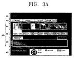
- Figures 3A to 3D are images illustrating examples of re-compressed and re-stored data, using the 'edit' menu screen displayed on the TV 300. Since the image recording and reproducing apparatus is set in the edit mode, the TV 300 displays the menu screen in the 'edit' mode, as shown in Figure 3A. The word 'Edit' is displayed on top of the menu screen, indicating the menu item 410 currently displayed on the menu screen. Additionally, 'Instructions' is displayed on the bottom 440 of the menu screen providing a link for guidance around the screen using the keys.
- Information about the keys of the remote controller 200 and the functions of the keys is also displayed at the bottom 440 of the menu screen.
- Sub-menus 420 for the current menu item 410 are displayed under the current menu item 410.
- items of 'Combine', 'Divide', 'Delete', 'Partial Delete', and 'Recomp(ression)' are illustrative of sub-menus of the 'Edit' menu.
- the main controller 180 controls the data management part 177 to read information about the video data stored in the HDD 171.
- the information about the video data may comprise the first (or representative key) frame of the video data, the title, the date of storage, running time and video quality.
- the main controller 180 controls the OSD part 185 to output a signal corresponding to the information, and the output signal is transmitted to the TV 300 via the second video path switch 150a, the video encoder 137, the switching part 123, and the line video and audio output terminal 116.
- the data information is displayed on a 'Recomp' window 430 as shown in Figure 3A.
- the 'Recomp' window 430 displays a video data list 431 currently stored in the HDD 171 by horizontally showing the first (or representative key) frame 431 a to 431f of respective video data. If the user moves the cursor downward on the 'Recomp' window using direction keys, the cursor is placed on the video data list 431, and video data information 433. The video item highlighted by the cursor is displayed at the bottom of the data list 431. More specifically, the cursor is placed on the first image 431a of the first video data such that the title, the date of storage, the running time and the image quality of the first video data are displayed as the video data information 433 shown in Figure 3A.
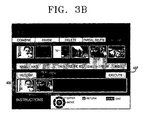
- FIG. 3B illustrates a resultant re-compression list displaying the first image 431 a and 431e from the first and fifth video data file as selected from the data list 431.
- a user moves the cursor down using the direction key and places the cursor on the 'Execute' icon 437, and presses the confirmation key.
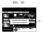
- a re-compression rate-setting window 450 appears in the centre of the screen.
- HQ high-quality
- SQL standard-quality
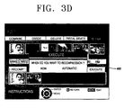
- a re-compression time setting window 460 is displayed in the center of the screen.
- the re-compression time setting window 460 is shown in Figure 3D and allows the user to determine when the re-compression should take place. If the user selects 'Now', re-compression of the selected data begins immediately. If the user selects 'Automatic', the selected video data will be re-compressed after the main switch of the image recording and reproducing apparatus is turned off by the user.
- the image recording and reproducing apparatus After the user selects video data from amongst the video data stored in the HDD 171 for re-compression, and sets the re-compression rate and time, the process of which was previously described, the image recording and reproducing apparatus performs re-compression with respect to the selected video data according to the selected re-compression rate and time.
- the processes for re-compression of the image recording and reproducing apparatus will be described in greater detail.
- the image recording and reproducing apparatus performs re-compression of the selected data at once. Accordingly, the main controller 180 controls the selected data stored in the HDD 171 so that it is transmitted to the MPEG decoder 183 via the data management part 177.
- the MPEG decoder 183 decodes the received MPEG-2 data to restore the digital video and audio signals. The digital video and audio signals are then output.
- the digital video signal output from the MPEG decoder 183 is fed into the MPEG encoder 161 via the second video path switch 150a and the first video path switch 140a.
- the digital audio signal output from the MPEG decoder 183 is input to the MPEG encoder 161 via through the second audio path switch 150b and the first audio path switch 140b.
- the main controller 180 controls the first and the second switch parts 140 and 150 so that a data transmission path is provided for the digital video and audio signals output from the MPEG decoder 183.
- the digital video and audio signals are then fed to the MPEG encoder 161.
- the MPEG encoder 161 re-compresses and re-stores the input digital video and audio signals according to the re-compression rate to the HDD 171. If the digital video and audio signals are recorded using 4Mbps or 2Mbps bitrate, 2GB or 1GB is required for 1-hour recording, respectively. When recording using MPEG-4 with 1Mbps bitrate, 0.5GB is required for 1-hour recording. Accordingly, if certain data previously recorded using 6Mbps bitrate is re-compressed using 4Mbps or 2Mbps or 1Mbps, the required storage capacity of the recording medium decreases to 2/3, 1/3 or 1/6, of the previously required amount respectively.
- the main controller 180 stores the list of the selected data to the SDRAM 187. Such selected data is re-compressed when the user turns off the main switch of the image recording and reproducing apparatus. The re-compression is performed in the same manner as the re-compression according to the 'Now' re-compression time.
- the main controller 180 controls the data management part 177 to read information about MPEG data stored to the HDD 171.
- the main controller 180 controls the OSD part 185 to output a signal corresponding to the read information.
- the output signal is transmitted to the TV 300 via the second video path switch 150a, the video encoder 137, the switching part 123, and the line video and audio output terminal 116.
- the data information may comprise the first (or representative) image of the video, the title, the date of storage, running time and image quality. These are displayed in the 'Recomp' window 430.
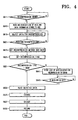
- the 'Recomp' window 430 displays the list of videos 431 currently stored in the HDD 171 and the data information about the video highlighted by the cursor, such as the title, the date of stroage, the running time and the image quality in step S613.
- the user moves the cursor around the video data list, highlighting the video data to be re-compressed, and presses the confirmation key, thereby selecting the data that will be re-compressed in step S615.
- the user In order to re-compress the data selected in step S615, the user has to move the cursor down using the direction key and place the cursor on the 'Execute' icon 437, and press the confirmation key to execute the command.
- the main controller 180 detects whether there is an execution command from the user in step S621.
- the re-compression rate setting window 450 is displayed in the centre of the screen.
- the user can select one of the two compression rates, e.g., the HQ method using the 4Mbps bitrate or the SQ method using 2Mbps bitrate, displayed on the re-compression rate setting window 450. This selection is made using the direction keys and the confirmation key in step S623.
- the re-compression time setting window 460 is displayed in the centre of the screen.
- the user selects between the 'Now' and 'Automatic' schedule for compressing the data in step S625. If the user selects 'Now', re-compression of the selected data begins immediately in step S631. Therefore, the main controller 180 controls the selected video stored in the HDD 171 to be fed to the MPEG decoder 183 via the data management part 177 in step S633.
- the MPEG decoder 183 decodes the received MPEG-2 data so as to restore the digital video and audio signals. The restored signals are then output from the MPEG decoder 183.
- the digital video signal output from the MPEG decoder 183 is input to the MPEG encoder 161 via the second video path switch 150a and the first video path switch 140a.
- the digital audio signal output from the MPEG decoder 183 is input to the MPEG encoder 161 via the second audio path switch 150b and the first audio path switch 140b.
- the main controller 180 controls the first and the second switch parts 140 and 150 to generate a video data transmission path such that the digital video and audio signals output from the MPEG decoder 183 can be input to the MPEG encoder 161 in step S635.
- the MPEG encoder 161 re-compresses the input digital video and audio signals according to the compression rate set by the user in step S637, and re-stores the signals to the HDD 171 in step S639. If the digital video and audio signals are recorded using the 4Mbps, 2Mbps or 1Mbps bitrate, 2GB, 1GB or 0.5GB storage space is required, respectively for a 1-hour recording. If certain video recorded using the 6Mbps bitrate and requiring 3GB for 1-hour recording, is re-compressed using 4Mbps, 2Mbps or 1Mbps, requirements for the storage capacity of the recording medium decrease respectively to 2/3, 1/3 or 1/6 of that originally required, thereby enabling effective use of the storage capacity of the recording medium.
- step 631 if the user selects 'Automatic' for the re-compression time, the main controller 180 stores the list of the selected data to the SDRAM 187 in step S641. After this, when the user turns off the main switch of the image recording and reproducing apparatus, the selected data start to be re-compressed in step S643. The re-compression is performed as in steps S633 to S639.
- video previously compressed and recorded in the recording medium can be re-compressed and re-recorded at higher compression rates. Accordingly, many inconveniences of having to delete pre-stored data for additional storage, replace the storage medium with the one of larger capacity, or add an extra storage medium when video data exceeds the capacity of the storage medium in use, can be prevented, and therefore, storage capacity of the storage medium of the present invention can be very efficiently used.
Landscapes
- Engineering & Computer Science (AREA)
- Signal Processing (AREA)
- Multimedia (AREA)
- Television Signal Processing For Recording (AREA)
- Signal Processing For Digital Recording And Reproducing (AREA)
- Compression Or Coding Systems Of Tv Signals (AREA)
Applications Claiming Priority (2)
| Application Number | Priority Date | Filing Date | Title |
|---|---|---|---|
| KR2003057572 | 2003-08-20 | ||
| KR1020030057572A KR100954397B1 (ko) | 2003-08-20 | 2003-08-20 | 저장된 데이터를 재압축하여 재기록하는 영상기록/재생장치 및 그의 데이터 재압축 기록방법 |
Publications (3)
| Publication Number | Publication Date |
|---|---|
| EP1519381A2 true EP1519381A2 (de) | 2005-03-30 |
| EP1519381A3 EP1519381A3 (de) | 2005-06-22 |
| EP1519381B1 EP1519381B1 (de) | 2011-10-12 |
Family
ID=34192154
Family Applications (1)
| Application Number | Title | Priority Date | Filing Date |
|---|---|---|---|
| EP04103943A Expired - Lifetime EP1519381B1 (de) | 2003-08-20 | 2004-08-17 | Vorrichtung und Verfahren zur Aufzeichnung digitaler Bilddaten |
Country Status (5)
| Country | Link |
|---|---|
| US (1) | US7668441B2 (de) |
| EP (1) | EP1519381B1 (de) |
| JP (1) | JP3911508B2 (de) |
| KR (1) | KR100954397B1 (de) |
| CN (1) | CN100474912C (de) |
Families Citing this family (11)
| Publication number | Priority date | Publication date | Assignee | Title |
|---|---|---|---|---|
| US7769274B2 (en) * | 2005-05-06 | 2010-08-03 | Mediatek, Inc. | Video processing and optical recording using a shared memory |
| US7788337B2 (en) * | 2005-12-21 | 2010-08-31 | Flinchem Edward P | Systems and methods for advertisement tracking |
| KR100778118B1 (ko) * | 2006-01-10 | 2007-11-21 | 삼성전자주식회사 | 네트워크로의 영상신호 전송기능을 향상한 dvr장치 및그의 영상신호 압축방법 |
| JP4551370B2 (ja) | 2006-07-18 | 2010-09-29 | 株式会社日立製作所 | 記録再生装置及び記録再生方法 |
| KR101197146B1 (ko) * | 2007-08-30 | 2012-11-08 | 삼성전자주식회사 | 화상형성장치 및 시스템과, 이 장치의 파일 관리방법 |
| US8155455B2 (en) * | 2008-03-10 | 2012-04-10 | Mediatek Inc. | Image capturing system and method thereof |
| DE102012216075A1 (de) * | 2012-09-11 | 2014-03-13 | Siemens Convergence Creators Gmbh | System zur Erfassung von Signaldaten |
| KR20160023160A (ko) * | 2014-08-21 | 2016-03-03 | 한화테크윈 주식회사 | 비디오 및 오디오 데이터의 관리 방법 |
| US9712830B1 (en) | 2016-09-15 | 2017-07-18 | Dropbox, Inc. | Techniques for image recompression |
| EP3572825A3 (de) | 2018-05-24 | 2019-12-11 | Siemens Healthcare GmbH | Wörterbuchkompression für magnetresonanzfingerprinting |
| US11961262B2 (en) | 2019-11-01 | 2024-04-16 | Lg Electronics Inc. | Signal processing apparatus and image display apparatus including same |
Citations (2)
| Publication number | Priority date | Publication date | Assignee | Title |
|---|---|---|---|---|
| JP2000341627A (ja) | 1999-05-28 | 2000-12-08 | Nec Corp | 映像及び音声信号の録画装置 |
| EP1195995A2 (de) | 2000-10-03 | 2002-04-10 | Pace Micro Technology PLC | Datenrekomprimierung in einer Speicherung |
Family Cites Families (27)
| Publication number | Priority date | Publication date | Assignee | Title |
|---|---|---|---|---|
| JPH02305053A (ja) | 1989-05-18 | 1990-12-18 | Matsushita Electric Ind Co Ltd | 音声蓄積装置 |
| US5237397A (en) * | 1991-12-24 | 1993-08-17 | Apple Computer, Inc. | Color video data processing |
| JP3230336B2 (ja) | 1993-05-27 | 2001-11-19 | キヤノン株式会社 | 再圧縮装置及び再圧縮システム |
| JP3166501B2 (ja) | 1994-09-13 | 2001-05-14 | 松下電器産業株式会社 | 画像再圧縮方法及び画像再圧縮装置 |
| JPH10257422A (ja) | 1997-03-13 | 1998-09-25 | Canon Inc | 画像記録再生装置 |
| JPH1166741A (ja) | 1997-08-18 | 1999-03-09 | Hitachi Ltd | 情報記録再生装置 |
| JP3748332B2 (ja) * | 1998-09-02 | 2006-02-22 | パイオニア株式会社 | 情報記録再生装置 |
| EP1003301A3 (de) * | 1998-11-19 | 2000-06-07 | NEC Corporation | Vorrichtung zur Lieferung von Programminformation und Aufnahme-/Wiedergabesteuervorrichtung |
| JP3284543B2 (ja) * | 1999-04-23 | 2002-05-20 | ソニー株式会社 | 情報処理装置、情報処理方法、およびプログラム格納媒体 |
| JP2001110167A (ja) * | 1999-10-08 | 2001-04-20 | Sanyo Electric Co Ltd | 記録装置及び該装置における記録方法 |
| JP3680738B2 (ja) * | 2001-01-24 | 2005-08-10 | 日本電気株式会社 | 波長多重光通信モジュール |
| KR100348703B1 (ko) | 2000-09-07 | 2002-08-14 | 주식회사 휴맥스 | 선택적 녹화 기능을 갖는 위성 방송 수신기와 선택적 녹화방법 |
| JP2002150678A (ja) | 2000-11-06 | 2002-05-24 | Aiwa Co Ltd | 記録再生装置及び情報記録方法 |
| US7200859B1 (en) * | 2000-11-22 | 2007-04-03 | Digeo, Inc. | Apparatus and method for intelligent multimedia compression and distribution |
| JP3450831B2 (ja) | 2001-02-08 | 2003-09-29 | 株式会社東芝 | 情報記憶装置、その制御プログラム、およびプログラム記録媒体 |
| JP3832567B2 (ja) * | 2001-03-07 | 2006-10-11 | 日本電気株式会社 | 番組記録装置及び方法 |
| WO2003046914A2 (en) | 2001-11-29 | 2003-06-05 | Matsushita Electric Industrial Co., Ltd. | Recording apparatus, recording program, and recording method |
| JP2003169291A (ja) | 2001-11-30 | 2003-06-13 | Canon Inc | 電子機器、データ送信方法、コンピュータ読み取り可能な記憶媒体及びコンピュータプログラム |
| JP2003189243A (ja) * | 2001-12-21 | 2003-07-04 | Victor Co Of Japan Ltd | 放送番組記録再生装置 |
| JP2003204307A (ja) * | 2002-01-09 | 2003-07-18 | Alpine Electronics Inc | 車載用受信機および車載システム |
| JP2003224822A (ja) | 2002-01-30 | 2003-08-08 | Toshiba Corp | ディジタル信号受信装置、ディジタル信号受信方法、ディジタル信号受信システム |
| JP2003244642A (ja) * | 2002-02-14 | 2003-08-29 | Funai Electric Co Ltd | デジタル録画装置およびその録画方法 |
| US7787741B2 (en) * | 2002-04-23 | 2010-08-31 | Gateway, Inc. | Prioritized content recording and storage management |
| KR100503452B1 (ko) * | 2002-12-27 | 2005-07-25 | 삼성전자주식회사 | 멀티미디어 데이터 기록장치 |
| US7197189B2 (en) * | 2003-05-15 | 2007-03-27 | Hewlett-Packard Development Company, L.P. | System and method having removable storage medium with data compression |
| US7966642B2 (en) * | 2003-09-15 | 2011-06-21 | Nair Ajith N | Resource-adaptive management of video storage |
| US20050111835A1 (en) * | 2003-11-26 | 2005-05-26 | Friel Joseph T. | Digital video recorder with background transcoder |
-
2003
- 2003-08-20 KR KR1020030057572A patent/KR100954397B1/ko not_active Expired - Fee Related
-
2004
- 2004-07-23 JP JP2004216507A patent/JP3911508B2/ja not_active Expired - Fee Related
- 2004-08-10 US US10/914,308 patent/US7668441B2/en not_active Expired - Fee Related
- 2004-08-17 EP EP04103943A patent/EP1519381B1/de not_active Expired - Lifetime
- 2004-08-20 CN CNB2004100569184A patent/CN100474912C/zh not_active Expired - Fee Related
Patent Citations (2)
| Publication number | Priority date | Publication date | Assignee | Title |
|---|---|---|---|---|
| JP2000341627A (ja) | 1999-05-28 | 2000-12-08 | Nec Corp | 映像及び音声信号の録画装置 |
| EP1195995A2 (de) | 2000-10-03 | 2002-04-10 | Pace Micro Technology PLC | Datenrekomprimierung in einer Speicherung |
Also Published As
| Publication number | Publication date |
|---|---|
| EP1519381A3 (de) | 2005-06-22 |
| CN100474912C (zh) | 2009-04-01 |
| US20050041958A1 (en) | 2005-02-24 |
| JP3911508B2 (ja) | 2007-05-09 |
| US7668441B2 (en) | 2010-02-23 |
| KR20050019656A (ko) | 2005-03-03 |
| EP1519381B1 (de) | 2011-10-12 |
| CN1585472A (zh) | 2005-02-23 |
| KR100954397B1 (ko) | 2010-04-26 |
| JP2005071572A (ja) | 2005-03-17 |
Similar Documents
| Publication | Publication Date | Title |
|---|---|---|
| JP4191042B2 (ja) | モバイルハンドヘルド装置用にビデオ番組を記録及び表示するためのシステム及び方法 | |
| US7558318B2 (en) | Method and apparatus for processing images, method and apparatus for recording and reproducing images, and television receiver utilizing the same | |
| CN100474909C (zh) | 在记录数字视频的同时进行实况图像显示 | |
| US20040028375A1 (en) | Video recording/reproducing apparatus and method of displaying menu guide | |
| JP2004056462A (ja) | 映像検索支援方法及び映像検索支援装置、並びに放送受信装置 | |
| JP2006503496A (ja) | データ管理方法 | |
| EP1519381B1 (de) | Vorrichtung und Verfahren zur Aufzeichnung digitaler Bilddaten | |
| JP2003179852A (ja) | 映像音声データ記録再生方法、及びそれを用いたディスク装置 | |
| JPH08237592A (ja) | 実時間映像記録/再生装置および方法、並びにビデオライブラリシステム | |
| US20060257103A1 (en) | Digital video recording apparatus and method thereof | |
| US20040252982A1 (en) | Recording apparatus, program, and integrated circuit | |
| CN1675922A (zh) | 显示在通电时可用的视频标题的数目的方法和装置 | |
| KR100436764B1 (ko) | 외장 기록방식을 지원하는 영상녹화재생장치 및 그 방법 | |
| US20080098182A1 (en) | Apparatus for information processing | |
| MXPA04010495A (es) | Metodo e interfaz para controlar un aparato grabador digital. | |
| JP4339743B2 (ja) | 映像記録方法および映像記録装置 | |
| JP3859073B2 (ja) | ハードディスクレコーダ | |
| KR100770905B1 (ko) | 디지털 방송녹화 재생 장치 및 방법 | |
| KR100503459B1 (ko) | 오류파일 자동삭제 기능을 가지는 영상 기록/재생장치 및그에 따른 오류파일 자동 삭제 방법 | |
| JP2004072782A (ja) | テレビジョン装置及び放送の受信制御方法 | |
| KR100595211B1 (ko) | Hd 방송 프로그램 녹화장치 및 방법 | |
| JP2002142180A (ja) | 記録再生装置及びタイマー予約記録方法 | |
| KR20060030235A (ko) | 휴대용 저장 매체를 이용한 방송 녹화/재생 장치 및 그 방법 | |
| KR20040079163A (ko) | 정지영상의 화면크기조정이 가능한 기록재생장치 및 그제어방법 | |
| JP2002142196A (ja) | 記録再生装置及び記録再生方法 |
Legal Events
| Date | Code | Title | Description |
|---|---|---|---|
| PUAI | Public reference made under article 153(3) epc to a published international application that has entered the european phase |
Free format text: ORIGINAL CODE: 0009012 |
|
| AK | Designated contracting states |
Kind code of ref document: A2 Designated state(s): AT BE BG CH CY CZ DE DK EE ES FI FR GB GR HU IE IT LI LU MC NL PL PT RO SE SI SK TR |
|
| AX | Request for extension of the european patent |
Extension state: AL HR LT LV MK |
|
| PUAL | Search report despatched |
Free format text: ORIGINAL CODE: 0009013 |
|
| AK | Designated contracting states |
Kind code of ref document: A3 Designated state(s): AT BE BG CH CY CZ DE DK EE ES FI FR GB GR HU IE IT LI LU MC NL PL PT RO SE SI SK TR |
|
| AX | Request for extension of the european patent |
Extension state: AL HR LT LV MK |
|
| 17P | Request for examination filed |
Effective date: 20050816 |
|
| AKX | Designation fees paid |
Designated state(s): DE GB IT NL |
|
| RTI1 | Title (correction) |
Free format text: A MEDIA RECORDING AND REPRODUCING DEVICE, METHOD THEREFORE |
|
| RIC1 | Information provided on ipc code assigned before grant |
Ipc: G11B 20/00 20060101ALI20110215BHEP Ipc: G11B 27/034 20060101AFI20110215BHEP Ipc: H04N 5/76 20060101ALI20110215BHEP Ipc: G11B 27/34 20060101ALI20110215BHEP Ipc: G11B 20/10 20060101ALI20110215BHEP |
|
| RTI1 | Title (correction) |
Free format text: APPARATUS AND METHOD FOR RECORDING DIGITAL IMAGE DATA |
|
| GRAP | Despatch of communication of intention to grant a patent |
Free format text: ORIGINAL CODE: EPIDOSNIGR1 |
|
| GRAS | Grant fee paid |
Free format text: ORIGINAL CODE: EPIDOSNIGR3 |
|
| GRAA | (expected) grant |
Free format text: ORIGINAL CODE: 0009210 |
|
| AK | Designated contracting states |
Kind code of ref document: B1 Designated state(s): DE GB IT NL |
|
| REG | Reference to a national code |
Ref country code: GB Ref legal event code: FG4D |
|
| REG | Reference to a national code |
Ref country code: DE Ref legal event code: R096 Ref document number: 602004034794 Country of ref document: DE Effective date: 20111215 |
|
| REG | Reference to a national code |
Ref country code: NL Ref legal event code: T3 |
|
| PLBE | No opposition filed within time limit |
Free format text: ORIGINAL CODE: 0009261 |
|
| STAA | Information on the status of an ep patent application or granted ep patent |
Free format text: STATUS: NO OPPOSITION FILED WITHIN TIME LIMIT |
|
| 26N | No opposition filed |
Effective date: 20120713 |
|
| REG | Reference to a national code |
Ref country code: DE Ref legal event code: R097 Ref document number: 602004034794 Country of ref document: DE Effective date: 20120713 |
|
| PGFP | Annual fee paid to national office [announced via postgrant information from national office to epo] |
Ref country code: NL Payment date: 20170720 Year of fee payment: 14 |
|
| PGFP | Annual fee paid to national office [announced via postgrant information from national office to epo] |
Ref country code: GB Payment date: 20170720 Year of fee payment: 14 Ref country code: DE Payment date: 20170720 Year of fee payment: 14 Ref country code: IT Payment date: 20170809 Year of fee payment: 14 |
|
| REG | Reference to a national code |
Ref country code: DE Ref legal event code: R119 Ref document number: 602004034794 Country of ref document: DE |
|
| REG | Reference to a national code |
Ref country code: NL Ref legal event code: MM Effective date: 20180901 |
|
| GBPC | Gb: european patent ceased through non-payment of renewal fee |
Effective date: 20180817 |
|
| PG25 | Lapsed in a contracting state [announced via postgrant information from national office to epo] |
Ref country code: NL Free format text: LAPSE BECAUSE OF NON-PAYMENT OF DUE FEES Effective date: 20180901 |
|
| PG25 | Lapsed in a contracting state [announced via postgrant information from national office to epo] |
Ref country code: DE Free format text: LAPSE BECAUSE OF NON-PAYMENT OF DUE FEES Effective date: 20190301 Ref country code: IT Free format text: LAPSE BECAUSE OF NON-PAYMENT OF DUE FEES Effective date: 20180817 |
|
| PG25 | Lapsed in a contracting state [announced via postgrant information from national office to epo] |
Ref country code: GB Free format text: LAPSE BECAUSE OF NON-PAYMENT OF DUE FEES Effective date: 20180817 |