EP1519085B1 - Mécanisme de blocage pour boîte de vitesses manuelle - Google Patents
Mécanisme de blocage pour boîte de vitesses manuelle Download PDFInfo
- Publication number
- EP1519085B1 EP1519085B1 EP20030103577 EP03103577A EP1519085B1 EP 1519085 B1 EP1519085 B1 EP 1519085B1 EP 20030103577 EP20030103577 EP 20030103577 EP 03103577 A EP03103577 A EP 03103577A EP 1519085 B1 EP1519085 B1 EP 1519085B1
- Authority
- EP
- European Patent Office
- Prior art keywords
- locking
- shift
- slot
- locking mechanism
- gate
- Prior art date
- Legal status (The legal status is an assumption and is not a legal conclusion. Google has not performed a legal analysis and makes no representation as to the accuracy of the status listed.)
- Expired - Lifetime
Links
- 230000007935 neutral effect Effects 0.000 claims description 15
- 238000006073 displacement reaction Methods 0.000 claims description 4
- 230000000903 blocking effect Effects 0.000 description 19
- 230000004888 barrier function Effects 0.000 description 2
- 238000000034 method Methods 0.000 description 2
- 230000005540 biological transmission Effects 0.000 description 1
- 238000005266 casting Methods 0.000 description 1
- 238000004519 manufacturing process Methods 0.000 description 1
Images
Classifications
-
- F—MECHANICAL ENGINEERING; LIGHTING; HEATING; WEAPONS; BLASTING
- F16—ENGINEERING ELEMENTS AND UNITS; GENERAL MEASURES FOR PRODUCING AND MAINTAINING EFFECTIVE FUNCTIONING OF MACHINES OR INSTALLATIONS; THERMAL INSULATION IN GENERAL
- F16H—GEARING
- F16H63/00—Control outputs from the control unit to change-speed- or reversing-gearings for conveying rotary motion or to other devices than the final output mechanism
- F16H63/02—Final output mechanisms therefor; Actuating means for the final output mechanisms
- F16H63/30—Constructional features of the final output mechanisms
- F16H63/34—Locking or disabling mechanisms
-
- F—MECHANICAL ENGINEERING; LIGHTING; HEATING; WEAPONS; BLASTING
- F16—ENGINEERING ELEMENTS AND UNITS; GENERAL MEASURES FOR PRODUCING AND MAINTAINING EFFECTIVE FUNCTIONING OF MACHINES OR INSTALLATIONS; THERMAL INSULATION IN GENERAL
- F16H—GEARING
- F16H61/00—Control functions within control units of change-speed- or reversing-gearings for conveying rotary motion ; Control of exclusively fluid gearing, friction gearing, gearings with endless flexible members or other particular types of gearing
- F16H61/24—Providing feel, e.g. to enable selection
- F16H2061/242—Mechanical shift gates or similar guiding means during selection and shifting
-
- F—MECHANICAL ENGINEERING; LIGHTING; HEATING; WEAPONS; BLASTING
- F16—ENGINEERING ELEMENTS AND UNITS; GENERAL MEASURES FOR PRODUCING AND MAINTAINING EFFECTIVE FUNCTIONING OF MACHINES OR INSTALLATIONS; THERMAL INSULATION IN GENERAL
- F16H—GEARING
- F16H63/00—Control outputs from the control unit to change-speed- or reversing-gearings for conveying rotary motion or to other devices than the final output mechanism
- F16H63/02—Final output mechanisms therefor; Actuating means for the final output mechanisms
- F16H63/08—Multiple final output mechanisms being moved by a single common final actuating mechanism
- F16H63/20—Multiple final output mechanisms being moved by a single common final actuating mechanism with preselection and subsequent movement of each final output mechanism by movement of the final actuating mechanism in two different ways, e.g. guided by a shift gate
- F16H2063/202—Multiple final output mechanisms being moved by a single common final actuating mechanism with preselection and subsequent movement of each final output mechanism by movement of the final actuating mechanism in two different ways, e.g. guided by a shift gate using cam plates for selection or shifting, e.g. shift plates with recesses or groves moved by a selector extension
Definitions
- the invention relates to a locking mechanism of a gearbox for positive guidance of a sliding pin, which is rigidly connected to a switching shaft of a gearbox.
- a locking mechanism of the above type is known for example from the generic DE 198 57 713 DE.
- the locking mechanism comprises a link plate with a gate section, in which engages the guide pin. Within the gate section of the guide pin is arranged movable.
- the gate section has a Wählgasse and a plurality of shift gates, which are arranged parallel and at equal distances from each other and are crossed by the Wählgasse substantially perpendicular.
- a locking device restricts the movement of the sliding pin in the selector gate.
- the locking device comprises a locking element with a nose against which the guide pin. The mobility of the locking element is limited by two stop pins, which are arranged above the link plate.
- the locking device comprises a collar formed on the switching shaft and a bolt which is displaceable via an electromagnet in the radial direction of the switching shaft. In a blocking position, the bolt engages behind the collar, so that an axial movement of the switching shaft and thus of the sliding pin is limited.
- the disclosed in DE 198 57 713 DE locking device comprises a plurality of components that must be precisely matched to each other, so that the locking mechanism can work exactly. In order to achieve an exact operation of the locking mechanism, the individual components must be manufactured within close manufacturing tolerances.
- the invention is therefore based on the object to provide a locking mechanism for positively guiding a sliding pin of a switching shaft, which has a simple structure and can be produced inexpensively.
- the object is achieved by a locking mechanism according to the claim 1.
- the fact that the blocking element projects into the gate section and that the gate section comprises a first and a second stop defining a first and a second end position, can be dispensed with additional stop pin on the link plate. This eliminates the complex alignment of the stop pin with respect to the link plate or with respect to the selector gate.
- the locking device comprises a locking lever on which the locking element abuts in the direction of movement when the locking lever is in a locking position.
- the blocking element comprises a barrier comb having a plurality of teeth arranged in a row, which project into the selection gate.
- the locking comb can be integrally formed with its teeth, so that an attachment or clamping of the teeth with each other is not necessary. So that the teeth in the selector gate can be moved back and forth, the depth or thickness of the teeth is smaller than the width of the selector gate.
- the teeth preferably each have a width that corresponds to the distance between two adjacent shift gates (the distance should be the distance between a lateral end of a shift gate and the adjacent lateral end of the adjacent shift gate.) corresponds to the width of a shift gate.
- the locking comb can be arranged in the selector gate such that the gap between two adjacent teeth allows unimpeded movement of the guide pin in a shift gate, the two teeth but at the same time, as far as the locking element is fixed, for an accurate guidance of the guide pin along the shift gate in Make crossing area with the selector gate.
- the blocking element is movable from a neutral position in the first or second end position by a respective displacement, the length of which corresponds to the sum of the width of a shift gate and the distance between two adjacent shift gates.
- the teeth are arranged in the selector gate so that the gaps between the teeth allows unimpeded movement of the sliding pin in the shift gate. If the (non-locked) locking device is pressed in one direction along the selector gate by means of the guide pin, the guide pin abuts a tooth of the locking device.
- the possible displacement is limited: The guide pin can only be performed in a directly adjacent shift gate. It is not possible to guide the guide pin along the selector gate into a next but one shift gate.
- the barrier comb at least n-1 teeth on a shift gate with n shift gates.
- the locking comb can thus comprise 3 teeth.
- the n-1 teeth can be arranged between the n shift gates.
- the first tooth between the first and second shift gate, the second tooth between the second and third shift gate and the third tooth between the third and fourth shift gate is arranged.
- the locking device may comprise a guide which engages in a parallel to the selection gate extending guide lane.
- the locking device By guiding it is prevented that the locking device can move without tilting or twisting in the selector gate.
- the guide lane is arranged in extension of the selector gate.
- the guide and the teeth of the ridge are in a plane.
- the guide can take the form of a tooth, without this tooth must have the same width as the other teeth. Also his distance to the nearest tooth is within limits selectable.
- the blocking element can be held in the neutral position by at least one restoring spring. It is useful to switch the blocking element between two return springs. If the blocking element to be moved from the neutral position in one of the two end positions, the force of the return springs must be overcome. This force is transmitted through the guide pin via a tooth on the blocking element. If the guide pin out of the selector gate in a shift gate, so that the guide pin is no longer applied to the tooth, the return springs press the locking element back into the neutral position.
- the neutral position is defined in this case by the balance of forces of the return springs. Preferred is a defined neutral position, which is independent of the tolerances and the wear of the spring.
- At least one stop for the return spring can be provided. If the return spring abuts on this stop, the blocking element is in a geometrically determined neutral position. This is independent of the balance of power of the return springs.
- the gate section of the cam plate at the two ends of Wählgasse extensions so that the selector gate beyond the crossing point with a first shift gate and beyond the crossing point with a last shift gate.
- the extension has at least one length which corresponds at least to the distance between adjacent shift lanes.
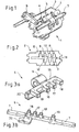
- FIG. 1 shows a locking mechanism 1 in a perspective view.
- the locking mechanism 1 comprises a cam plate 2 with a gate section 3 and a locking device 4 with a blocking element 5 and a locking lever 6.
- the blocking element 5 is arranged movably on a shaft 7, which runs parallel to a selector shaft, not shown here. In the illustrated position of the locking lever 6, against which the locking device 5, which is movable axially relative to the switching shaft, a movement of the locking device is possible only in one direction.
- Figure 2 shows the link plate 2 with the gate section 3 in plan view.
- the gate section comprises four parallel shift gates 8, 9, 10, 11, which each have an equal distance to each other.
- the link plate can be used for a manual transmission with 6 gears and a reverse gear, which is illustrated by the attached at the ends of the shift gates numbers R and 1 to 6.
- Figure 2 shows a rigidly connected to the switching shaft guide pin 12, which engages from below through the plane of Figure 2 through the link plate, at the upper end of the shift gate 9. In this position of the guide pin 12, the 1st gear of the gearbox is connected.
- a Wählgasse 13 sen sen perpendicular to the shift gates 8 to 11 and connects them with each other.
- FIG. 3 a shows an embodiment of the blocking element 5 in a perspective view.
- a sleeve 14 with a cylindrical inner surface provides for the axially movable mounting of the locking element 5.
- On the sleeve 14 integrally formed is a locking comb 15 with three teeth 16, 17 and 18 and with a guide 19 which is also formed as a tooth.
- the locking device 5 comprises a stop 20 which cooperates with the locking lever 6 for axial (partial) locking.
- Figure 1 it is clear that the teeth 16, 17 and 18 of the locking element 5 reach into the selector gate 13.
- Figure 3b shows a second embodiment of the locking element 5, preferably made of two joined sheets.
- the blocking element 5 and the shaft 7 are rigidly connected, and the shaft 7 is slidably mounted parallel to the switching shaft. This advantageously results in an increased guide length of the locking element 5.
- the blocking element can also be in one piece, z. B. be executed as a casting.
- the stop 20 can be arranged as a separate part on the blocking element 5 or be an integral part of the blocking element 5.
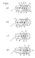
- FIGS. 4a to 4d A possible switching and dialing process is shown by way of example with reference to FIGS. 4a to 4d. Other switching and dialing procedures are analogous to the examples shown here.
- Figure 4a shows the link plate of Figure 2 with the guide pin 12 (now in another position) and with the teeth 16, 17 and 18 shown in section.
- the guide 19 is also shown in section and is located in a guide lane 21, which is an extension the selection gate 13 represents.
- the guide 19 serves to prevent rotation of the locking device 5.
- the teeth 16, 17 and 18 of the locking device 5 are arranged in the selector gate between two shift gates.
- the guide pin 12 is located in the shift gate 11 5th gear is engaged.
- Figures 4a and 4b show in conjunction, as the locking device 5 with the teeth 16, 17 and 18 and with the guide 19, the movement of the guide pin in the selector gate limited.
- the guide pin 12 is guided in the middle of Wählgasse 11 and pressed against the tooth 18. If the locking element 5 is not locked, the locking device 5 is pressed to the left until the guide 19 at a first stop 22, which defines the end of the guide lane 21, rests (see Figure 4b).
- FIG. 4b shows the blocking element 5 in a first end position. If now the guide pin along the shift gate 10 moves to insert the 4th gear, the blocking element 5, for example, due to return springs, which are not shown, return to the neutral position. It is clear that a shift back from 5th gear in the 1st or 2nd gear due to the locking element is not possible.
- Figure 4d shows the teeth 16, 17 and 18 of the locking device 5 in a second end position.
- the guide pin 12 now pushes the tooth 18 to the right through the shift gate 11 until it bears against a second stop 23 of the gate section 3.
Landscapes
- Engineering & Computer Science (AREA)
- General Engineering & Computer Science (AREA)
- Mechanical Engineering (AREA)
- Gear-Shifting Mechanisms (AREA)
Claims (14)
- Mécanisme de blocage (1) d'une boîte de vitesses pour le guidage forcée d'une tige de coulisse (12) qui est connecté rigidement à un arbre de commutation d'une boîte de vitesses, comprenant :a) un plateau à coulisse (2) comprenant une section de coulisse (3) qui comprend une voie de sélection (13) et plusieurs voies de commutation (8, 9, 10, 11),- les voies de commutation (8, 9, 10, 11) étant disposées essentiellement parallèlement et à distances égales les unes des autres et étant croisées essentiellement perpendiculairement par la voie de sélection (13), et- la tige de coulisse (12) venant en prise dans la section de coulisse (3) ;b) un dispositif de blocage (4) pour limiter le mouvement de la tige de coulisse (12) dans la voie de sélection (13), avec au moins un élément de blocage (5) qui est disposé de manière déplaçable le long de la voie de sélection (13) entre une première et une deuxième position d'extrémité,caractérisé en ce que
l'élément de blocage (5) pénètre dans la section de coulisse (3), l'élément de blocage (5) s'appliquant dans la première position d'extrémité contre une première butée (22) de la section de coulisse (3) et dans la deuxième position d'extrémité contre une deuxième butée (23) de la section de coulisse (3). - Mécanisme de blocage (1) selon la revendication 1,
caractérisé en ce que
le dispositif de blocage (4) comprend au moins un levier de blocage (6) contre lequel s'applique l'élément de blocage (5) dans la direction longitudinale de la voie de sélection (13) lorsque le levier de blocage (6) se trouve dans une position de blocage. - Mécanisme de blocage (1) selon la revendication 1 ou 2,
caractérisé en ce que
l'élément de blocage (5) comprend un peigne de blocage (15) avec plusieurs dents (16, 17, 18) disposées en rangée, qui pénètrent dans la voie de sélection (13) . - Mécanisme de blocage (1) selon la revendication 3,
caractérisé en ce que
les dents (16, 17, 18) présentent chacune une largeur identique et présentent un espacement identique par rapport aux dents voisines, la largeur d'une dent correspondant à la distance entre deux voies de commutation (8, 9, 10, 11) et la distance entre les dents (16, 17, 18) correspondant à la largeur d'une voie de commutation (8, 9, 10, 11). - Mécanisme de blocage (1) selon l'une quelconque des revendications 1 à 4,
caractérisé en ce que
depuis une position neutre de l'élément de blocage (5), celui-ci peut être déplacé dans la première ou la deuxième position d'extrémité d'une course de déplacement respective qui se compose de la largeur d'une voie de commutation et de la distance entre deux voies de commutation adjacentes. - Mécanisme de blocage (1) selon l'une quelconque des revendications 3 à 5,
caractérisé en ce que
le peigne de blocage (15) présente au moins n-1 dents pour n voies de commutation. - Mécanisme de blocage (1) selon la revendication 6,
caractérisé en ce que
dans la position neutre du peigne de blocage (15) les n-1 dents sont disposées entre la première voie de commutation (8) et la n-ième voie de commutation (11). - Mécanisme de blocage (1) selon l'une quelconque des revendications 1 à 7,
caractérisé en ce que
l'élément de blocage (5) comprend une coulisse (19) qui vient en prise dans une voie de guidage (21) du plateau à coulisse (2) s'étendant parallèlement à la voie de sélection (13). - Mécanisme de blocage (1) selon la revendication 8,
caractérisé en ce que
la voie de guidage (21) est disposée dans le prolongement de la voie de sélection (13). - Mécanisme de blocage (1) selon l'une quelconque des revendications 1 à 9, caractérisé en ce que l'élément de blocage (5) est maintenu dans la position neutre par au moins un ressort de rappel.
- Mécanisme de blocage (1) selon la revendication 10,
caractérisé en ce que
la position neutre est définie par une butée pour le ressort de rappel. - Mécanisme de blocage (1) selon l'une quelconque des revendications précédentes,
caractérisé en ce que
l'élément de blocage (5) est connecté fixement à l'arbre (7) et l'arbre (7) est monté de manière déplaçable en longueur. - Mécanisme de blocage (1) selon la revendication 12,
caractérisé en ce que
l'élément de blocage (5) et l'arbre (7) sont réalisés d'une seule pièce. - Mécanisme de blocage (1) selon l'une quelconque des revendications précédentes,
caractérisé en ce que
la section de coulisse (3) présente au niveau des deux extrémités de la voie de sélection (13) à chaque fois un prolongement qui se prolonge au-delà du point d'intersection avec la première voie de commutation (8) respectivement au-delà du point d'intersection avec la n-ième voie de commutation (11), chaque prolongement s'étendant sur au moins une longueur qui correspond à l'espacement entre deux voies de commutation voisines.
Priority Applications (2)
| Application Number | Priority Date | Filing Date | Title |
|---|---|---|---|
| DE50304591T DE50304591D1 (de) | 2003-09-26 | 2003-09-26 | Sperrmechanismus eines Schaltgetriebes |
| EP20030103577 EP1519085B1 (fr) | 2003-09-26 | 2003-09-26 | Mécanisme de blocage pour boîte de vitesses manuelle |
Applications Claiming Priority (1)
| Application Number | Priority Date | Filing Date | Title |
|---|---|---|---|
| EP20030103577 EP1519085B1 (fr) | 2003-09-26 | 2003-09-26 | Mécanisme de blocage pour boîte de vitesses manuelle |
Publications (2)
| Publication Number | Publication Date |
|---|---|
| EP1519085A1 EP1519085A1 (fr) | 2005-03-30 |
| EP1519085B1 true EP1519085B1 (fr) | 2006-08-09 |
Family
ID=34178599
Family Applications (1)
| Application Number | Title | Priority Date | Filing Date |
|---|---|---|---|
| EP20030103577 Expired - Lifetime EP1519085B1 (fr) | 2003-09-26 | 2003-09-26 | Mécanisme de blocage pour boîte de vitesses manuelle |
Country Status (2)
| Country | Link |
|---|---|
| EP (1) | EP1519085B1 (fr) |
| DE (1) | DE50304591D1 (fr) |
Cited By (3)
| Publication number | Priority date | Publication date | Assignee | Title |
|---|---|---|---|---|
| DE102008000970A1 (de) | 2008-04-03 | 2009-10-08 | Zf Friedrichshafen Ag | Schalteinrichtung mit Sperrmechanismus |
| DE102012015619A1 (de) | 2012-08-07 | 2013-03-07 | Daimler Ag | Getriebebetätigungseinheit für ein Handschaltgetriebe eines Kraftfahrzeugs |
| CN105829779A (zh) * | 2013-12-18 | 2016-08-03 | 舍弗勒技术股份两合公司 | 确定优选用于机动车辆的变速器执行器的参考位置的方法以及用于机动车辆变速器的变速器执行器 |
Families Citing this family (4)
| Publication number | Priority date | Publication date | Assignee | Title |
|---|---|---|---|---|
| DE102006017158B4 (de) * | 2005-05-07 | 2022-04-21 | Schaeffler Technologies AG & Co. KG | Getriebeaktor für eine Kraftfahrzeug-Getriebeeinrichtung, Kraftfahrzeug-Getriebeeinrichtung mit einem Getriebeaktor sowie Kraftfahrzeug Antriebsstrang mit einer Kraftfahrzeug-Getriebeeinrichtung |
| JP4809629B2 (ja) * | 2005-05-25 | 2011-11-09 | アイシン・エーアイ株式会社 | 変速操作装置 |
| DE102013202273A1 (de) * | 2013-02-13 | 2014-08-14 | Zf Friedrichshafen Ag | Schalteinrichtung mit einer Kulissenführung für ein Fahrzeuggetriebe |
| WO2021040541A1 (fr) * | 2019-08-30 | 2021-03-04 | Johnson Alan Blake | Fixation pour levier de boîte de vitesses de véhicule |
Family Cites Families (4)
| Publication number | Priority date | Publication date | Assignee | Title |
|---|---|---|---|---|
| US2684600A (en) * | 1949-12-28 | 1954-07-27 | Daimler Benz Ag | Shifting mechanism for transmissions |
| US4633728A (en) * | 1985-09-05 | 1987-01-06 | Ford Motor Company | Gear selector control for manual transmission |
| DE3913269A1 (de) * | 1989-04-22 | 1990-10-31 | Ford Werke Ag | Schaltvorrichtung fuer wechselgetriebe von kraftfahrzeugen |
| JPH11270672A (ja) * | 1997-12-18 | 1999-10-05 | Aft Atlas Fahrzeugtechnik Gmbh | 操作装置 |
-
2003
- 2003-09-26 DE DE50304591T patent/DE50304591D1/de not_active Expired - Lifetime
- 2003-09-26 EP EP20030103577 patent/EP1519085B1/fr not_active Expired - Lifetime
Cited By (4)
| Publication number | Priority date | Publication date | Assignee | Title |
|---|---|---|---|---|
| DE102008000970A1 (de) | 2008-04-03 | 2009-10-08 | Zf Friedrichshafen Ag | Schalteinrichtung mit Sperrmechanismus |
| DE102012015619A1 (de) | 2012-08-07 | 2013-03-07 | Daimler Ag | Getriebebetätigungseinheit für ein Handschaltgetriebe eines Kraftfahrzeugs |
| CN105829779A (zh) * | 2013-12-18 | 2016-08-03 | 舍弗勒技术股份两合公司 | 确定优选用于机动车辆的变速器执行器的参考位置的方法以及用于机动车辆变速器的变速器执行器 |
| CN105829779B (zh) * | 2013-12-18 | 2018-09-21 | 舍弗勒技术股份两合公司 | 确定变速器执行器的参考位置的方法以及变速器执行器 |
Also Published As
| Publication number | Publication date |
|---|---|
| EP1519085A1 (fr) | 2005-03-30 |
| DE50304591D1 (de) | 2006-09-21 |
Similar Documents
| Publication | Publication Date | Title |
|---|---|---|
| EP0408932B1 (fr) | Dispositif de blocage pour sièges réglables de véhicules | |
| EP2175176B1 (fr) | Dispositif de commutation pour une boîte de vitesse à plusieurs vitesses doté d'un dispositif de verrouillage | |
| DE102008060167A1 (de) | Ventiltrieb einer Brennkraftmaschine | |
| DE2313366A1 (de) | Schaltmechanismus fuer getriebekaesten | |
| DE60016257T2 (de) | Ziehkeilschaltgetriebe | |
| DE19805924A1 (de) | Getriebe | |
| DE69123335T2 (de) | Einrichtung für das Justieren der Länge einer Stange, insbesondere eine Stange für die Operation eines Fahrzeugschlosses | |
| DE3408090C2 (fr) | ||
| EP0846797B1 (fr) | Métier à tricoter chaíne comportant une barre à passettes Jacquard | |
| EP1519085B1 (fr) | Mécanisme de blocage pour boîte de vitesses manuelle | |
| DE2727833C2 (de) | Schiebemechanismus einer Schalteinrichtung für ein Kraftfahrzeuggetriebe | |
| DE2653035C3 (de) | Schaltvorrichtung für ein Kraftfahrzeugwechselgetriebe | |
| DE3125632C1 (de) | Schaltvorrichtung für ein Wechselgetriebe, insbesondere in Kraftfahrzeugen | |
| EP0412279A2 (fr) | Dispositif de changement de vitesses pour la boîte de vitesses d'une voiture | |
| DE4424543A1 (de) | Schalthebelanordnung für ein Getriebe | |
| DE1650820B1 (de) | Schaltvorrichtung fuer zwei schaltgabeln zum eingriff mit zwei schiebemuffen eines wechselgetriebes | |
| EP2179200B1 (fr) | Dispositif de passage des vitesses pour une boîte de vitesses d'un véhicule motorisé comportant un dispositif de verrouillage | |
| EP3108159B1 (fr) | Dispositif de commande pour une boîte de vitesses | |
| EP1236936B1 (fr) | Mécanisme de verrouillage pour commande de changement de vitesse | |
| DE1163688B (de) | Schalt- und Sperrvorrichtung fuer Wechselgetriebe von Kraftfahrzeugen | |
| WO2016034336A1 (fr) | Arbre à cames pourvu d'une coulisse de commutation | |
| EP0752549B1 (fr) | Dispositif de changement de vitesses pour transmissions véhiculaires | |
| DE102008000970A1 (de) | Schalteinrichtung mit Sperrmechanismus | |
| DE102018206392A1 (de) | Schalteinrichtung zur durchführung von gangwechseln in einem fahrzeuggetriebe | |
| DE2926928C2 (de) | "Mustergetriebe für Kettenwirkmaschinen o.dgl. |
Legal Events
| Date | Code | Title | Description |
|---|---|---|---|
| PUAI | Public reference made under article 153(3) epc to a published international application that has entered the european phase |
Free format text: ORIGINAL CODE: 0009012 |
|
| 17P | Request for examination filed |
Effective date: 20040317 |
|
| AK | Designated contracting states |
Kind code of ref document: A1 Designated state(s): AT BE BG CH CY CZ DE DK EE ES FI FR GB GR HU IE IT LI LU MC NL PT RO SE SI SK TR |
|
| AX | Request for extension of the european patent |
Extension state: AL LT LV MK |
|
| AKX | Designation fees paid |
Designated state(s): DE FR GB |
|
| GRAP | Despatch of communication of intention to grant a patent |
Free format text: ORIGINAL CODE: EPIDOSNIGR1 |
|
| GRAS | Grant fee paid |
Free format text: ORIGINAL CODE: EPIDOSNIGR3 |
|
| GRAA | (expected) grant |
Free format text: ORIGINAL CODE: 0009210 |
|
| AK | Designated contracting states |
Kind code of ref document: B1 Designated state(s): DE FR GB |
|
| REG | Reference to a national code |
Ref country code: GB Ref legal event code: FG4D Free format text: NOT ENGLISH |
|
| REF | Corresponds to: |
Ref document number: 50304591 Country of ref document: DE Date of ref document: 20060921 Kind code of ref document: P |
|
| GBT | Gb: translation of ep patent filed (gb section 77(6)(a)/1977) |
Effective date: 20061115 |
|
| ET | Fr: translation filed | ||
| PLBE | No opposition filed within time limit |
Free format text: ORIGINAL CODE: 0009261 |
|
| STAA | Information on the status of an ep patent application or granted ep patent |
Free format text: STATUS: NO OPPOSITION FILED WITHIN TIME LIMIT |
|
| 26N | No opposition filed |
Effective date: 20070510 |
|
| REG | Reference to a national code |
Ref country code: FR Ref legal event code: PLFP Year of fee payment: 13 |
|
| REG | Reference to a national code |
Ref country code: FR Ref legal event code: PLFP Year of fee payment: 14 |
|
| REG | Reference to a national code |
Ref country code: FR Ref legal event code: PLFP Year of fee payment: 15 |
|
| REG | Reference to a national code |
Ref country code: FR Ref legal event code: PLFP Year of fee payment: 16 |
|
| PGFP | Annual fee paid to national office [announced via postgrant information from national office to epo] |
Ref country code: DE Payment date: 20190813 Year of fee payment: 17 Ref country code: FR Payment date: 20190819 Year of fee payment: 17 |
|
| PGFP | Annual fee paid to national office [announced via postgrant information from national office to epo] |
Ref country code: GB Payment date: 20190827 Year of fee payment: 17 |
|
| REG | Reference to a national code |
Ref country code: DE Ref legal event code: R119 Ref document number: 50304591 Country of ref document: DE |
|
| GBPC | Gb: european patent ceased through non-payment of renewal fee |
Effective date: 20200926 |
|
| PG25 | Lapsed in a contracting state [announced via postgrant information from national office to epo] |
Ref country code: FR Free format text: LAPSE BECAUSE OF NON-PAYMENT OF DUE FEES Effective date: 20200930 Ref country code: DE Free format text: LAPSE BECAUSE OF NON-PAYMENT OF DUE FEES Effective date: 20210401 |
|
| PG25 | Lapsed in a contracting state [announced via postgrant information from national office to epo] |
Ref country code: GB Free format text: LAPSE BECAUSE OF NON-PAYMENT OF DUE FEES Effective date: 20200926 |