EP2179200B1 - Dispositif de passage des vitesses pour une boîte de vitesses d'un véhicule motorisé comportant un dispositif de verrouillage - Google Patents
Dispositif de passage des vitesses pour une boîte de vitesses d'un véhicule motorisé comportant un dispositif de verrouillage Download PDFInfo
- Publication number
- EP2179200B1 EP2179200B1 EP08760672A EP08760672A EP2179200B1 EP 2179200 B1 EP2179200 B1 EP 2179200B1 EP 08760672 A EP08760672 A EP 08760672A EP 08760672 A EP08760672 A EP 08760672A EP 2179200 B1 EP2179200 B1 EP 2179200B1
- Authority
- EP
- European Patent Office
- Prior art keywords
- shift
- locking
- guide
- section
- shaft
- Prior art date
- Legal status (The legal status is an assumption and is not a legal conclusion. Google has not performed a legal analysis and makes no representation as to the accuracy of the status listed.)
- Active
Links
- 230000005540 biological transmission Effects 0.000 title abstract description 18
- 239000002184 metal Substances 0.000 claims abstract description 24
- 238000006073 displacement reaction Methods 0.000 abstract description 10
- 238000004519 manufacturing process Methods 0.000 description 5
- 238000003780 insertion Methods 0.000 description 3
- 230000037431 insertion Effects 0.000 description 3
- 230000008878 coupling Effects 0.000 description 2
- 238000010168 coupling process Methods 0.000 description 2
- 238000005859 coupling reaction Methods 0.000 description 2
- 238000000034 method Methods 0.000 description 2
- 206010044684 Trismus Diseases 0.000 description 1
- 238000005452 bending Methods 0.000 description 1
- 239000002131 composite material Substances 0.000 description 1
- 230000001419 dependent effect Effects 0.000 description 1
- 230000000694 effects Effects 0.000 description 1
- 238000004080 punching Methods 0.000 description 1
- 238000000926 separation method Methods 0.000 description 1
- 230000000087 stabilizing effect Effects 0.000 description 1
- 238000003466 welding Methods 0.000 description 1
Images


Classifications
-
- F—MECHANICAL ENGINEERING; LIGHTING; HEATING; WEAPONS; BLASTING
- F16—ENGINEERING ELEMENTS AND UNITS; GENERAL MEASURES FOR PRODUCING AND MAINTAINING EFFECTIVE FUNCTIONING OF MACHINES OR INSTALLATIONS; THERMAL INSULATION IN GENERAL
- F16H—GEARING
- F16H63/00—Control outputs from the control unit to change-speed- or reversing-gearings for conveying rotary motion or to other devices than the final output mechanism
- F16H63/02—Final output mechanisms therefor; Actuating means for the final output mechanisms
- F16H63/30—Constructional features of the final output mechanisms
- F16H63/34—Locking or disabling mechanisms
- F16H63/3408—Locking or disabling mechanisms the locking mechanism being moved by the final actuating mechanism
-
- F—MECHANICAL ENGINEERING; LIGHTING; HEATING; WEAPONS; BLASTING
- F16—ENGINEERING ELEMENTS AND UNITS; GENERAL MEASURES FOR PRODUCING AND MAINTAINING EFFECTIVE FUNCTIONING OF MACHINES OR INSTALLATIONS; THERMAL INSULATION IN GENERAL
- F16H—GEARING
- F16H63/00—Control outputs from the control unit to change-speed- or reversing-gearings for conveying rotary motion or to other devices than the final output mechanism
- F16H63/02—Final output mechanisms therefor; Actuating means for the final output mechanisms
- F16H63/08—Multiple final output mechanisms being moved by a single common final actuating mechanism
- F16H63/20—Multiple final output mechanisms being moved by a single common final actuating mechanism with preselection and subsequent movement of each final output mechanism by movement of the final actuating mechanism in two different ways, e.g. guided by a shift gate
-
- F—MECHANICAL ENGINEERING; LIGHTING; HEATING; WEAPONS; BLASTING
- F16—ENGINEERING ELEMENTS AND UNITS; GENERAL MEASURES FOR PRODUCING AND MAINTAINING EFFECTIVE FUNCTIONING OF MACHINES OR INSTALLATIONS; THERMAL INSULATION IN GENERAL
- F16H—GEARING
- F16H63/00—Control outputs from the control unit to change-speed- or reversing-gearings for conveying rotary motion or to other devices than the final output mechanism
- F16H63/02—Final output mechanisms therefor; Actuating means for the final output mechanisms
- F16H63/30—Constructional features of the final output mechanisms
- F16H63/38—Detents
Definitions
- the invention relates to a switching device for a manual transmission of a motor vehicle with a locking device, with a selector shaft for preselection and for shifting gears in the transmission, with a plurality of shift rails for transmitting the switching torque from the shift shaft to the transmission, wherein the shift shaft perpendicular to the Gear shift rails is aligned and for the selection of gears axially displaceable and pivotally arranged for shifting gears about its own axis, wherein the locking device comprises a locking portion for releasing one of the shift rails and for locking the other shift rails and a guide portion for axially guiding the locking device to a housing Having guide member, wherein the locking device is formed and / or arranged so that they entrained in an axial displacement of the shift shaft for preselection of the gears and at a pivoting the shift axle freewheeling for shifting the gears.
- a problem in particular with a manual shift of gears is when incorrectly not one of the two gears of the desired shift rail is inserted, but "switched diagonally", so that a gear of one of the other shift rails is switched. Such a "connection” leads to the insertion of a wrong gear, so that in the worst case the speed and direction of rotation of the gearbox and drive motor do not match and unexpected driving situations or even damage to the gearbox or the drive motor can occur.
- locking systems are known, which are arranged and formed between the shift shaft and gearbox that locks the non-selected shift rails and only the selected shift rail is released for a switching operation.
- the locking system thus ensures that the driver can insert only one gear in the selected shift gate or the selected shift rail by a switching movement.
- Such a locking system is for example from the document DE 30 111 31 A1 known, which relates to a switching device for a mechanical gear change gearbox of motor vehicles.
- a Heidelberggasseninfolmony the shift shaft with respect to the achievement of certain shift gates limiting locking device is disclosed.
- This locking device is designed as a locking plate, which is threaded over two legs on the shift shaft, wherein the locking plate is carried by means of an annular collar-shaped shoulder between the two legs in the axial adjustment of the shift shaft. A rotation of the locking plate is prevented by engagement of a fixed to a transmission housing locking screw which engages in an upper side of the locking plate.
- the publication DE 39 132 69 A1 which probably forms the closest prior art, relates to a switching device for gearboxes of motor vehicles, which also has a switching shaft for transmitting selection and switching torques. Also, this switching device shows a locking plate, which is entrained by a collar of a shift finger in the axial direction, whereas the shift finger or the shift shaft is rotatable in the circumferential direction relative to the locking plate. Likewise, this locking plate is held against rotation via a bolt / slot connection. The bolt / slot connection is arranged in an axial plan view of the switching device at a 90 ° angle relative to the locking region.
- the generic DE 44 43 523 C1 discloses a switching arrangement with a plurality of shift rails, which are actuated by a shift finger.
- the shift finger is flanked by locking cams on both sides. These locking cams allow the operation of a single shift rod by the shift finger.
- the corresponding to the locking cam guide is arranged on the opposite side of the shift shaft.
- the invention has for its object to provide a switching device with locking device for locking shift rails for a manual transmission of motor vehicles, which is reliable and inexpensive.
- a switching device with locking device for locking shift rails for a manual transmission of motor vehicles wherein the transmission is preferably designed as a mechanical, multi-speed change-speed gearbox.
- components of the switching device include a switching shaft, which is preferably actuated via a manual shift lever and which for preselection and arranged and / or formed for shifting gears in the manual transmission.
- a plurality of shift rails preferably three shift rails for switching six gears is provided.
- a corresponding number of shift rails for shifting a different number of gears can be realized.
- the shift shaft - in particular in a plan view in the radial direction of the shift shaft - aligned perpendicular or substantially perpendicular to the shift rails.
- the switching shaft is axially displaceable for the selection of gears or shift rails along its own axis and pivotally arranged for shifting gears about its own axis.
- the shift shaft on a shift finger which can be moved by an axial displacement of the shift shaft between the shift rails and shifts a selected shift rail in its longitudinal extent by pivoting the shift shaft about its own axis to engage the appropriate gear.
- the locking system comprises a one- or multi-part locking device, which shows at least two functional areas:
- a functional area relates to a locking portion which releases one of the shift rails in a selected position and locks the other shift rails at the same time. Changing the preselection also changes the released shift rail.
- Another functional area relates to a guide portion, which is designed for axial guidance, in particular in the axial extent of the switching shaft, the locking device together with a housing-fixed guide member.
- the guide member to a Wegdomgetude which receives the shift shaft and the shift rails, at least in sections, and / or a transmission housing rigidly and / or stationary.
- the axial guide is preferably formed so that the locking device is guided against rotation in the circumferential direction about the shift shaft.
- the locking device is designed and / or arranged so that it is carried on an axial displacement of the shift shaft for preselection of the gears to - as already explained - release one of the shift rails and lock the other, and at a pivoting of the shift axis for insertion the gears, however, freewheeled and mechanically decoupled from the pivotal movement of the shift shaft.
- the locking portion is formed as a first planar sheet metal portion defining a locking plane in surface extension.
- a flat sliding and / or displacement plane which is defined as a management level.
- Locking section and guide section are preferably arranged offset to one another in the axial direction of the switching shaft and / or positioned parallel and / or congruent with one another in axial plan view and / or overlapping.
- the locking plane and the guide plane are arranged coplanar to each other, wherein the two planes coincide.
- a consideration of the invention is that the known from the prior art locking systems constructed with locking plates mechanically complicated and are particularly expensive to manufacture and assembly. This is not least because the locking areas and the guide areas of the known locking plates are arranged relative to the switching shaft opposite or at a 90 ° angle to each other. This arrangement means that the locking plates must be realized as a complex 3-D structure whose low-tolerance manufacturing and assembly is associated with a lot of effort.
- the invention proposes the locking portion and the guide portion on a common side of the To arrange switching shaft, resulting in a manufacturing simplification.
- the guide section of the guide element has a second flat sheet metal section whose surface extension defines the sliding plane.
- locking portion and guide portion are each mitgestaltet by a flat sheet metal portion, wherein the planes defined by the sheet metal sections are arranged parallel to each other and / or coplanar.
- first and second planar sheet metal sections form a common, flat sheet metal section.
- the production of the locking device is particularly simple, since the locking section and guide section by a simple separation process, for example, by a punched, can be produced. In particular, no forming steps are necessary in the area of said two sections.
- the locking device in the region of said two sections is inexpensive and manufacturable with high accuracy.
- the locking portion has a recess open at the edge, which is formed for example in the form of a rectangle whose width is adapted to the width of one of the shift rails such that in each case the other shift rails are locked.
- the recess thus forms a passage area for exactly one shift rail.
- the shift rails on locking mouths in which engages the locking portion.
- the locking mouths also have a preferably rectangular cross-section in a lateral plan view.
- either the guide portion or the guide member comprise an axially, in particular in the axial extent of the switching shaft, aligned guide channel, whereas the respective partner, so the guide member or the guide portion, a guide element, in particular a guide pin which is guided by the guide channel in the axial direction.
- the longitudinal extent of the guide element is arranged so that it is arranged in an axial plan view of the switching shaft perpendicular to the shift shaft, but this does not intersect.
- the locking device For mechanical coupling, the locking device and the switching shaft, the locking device has a driving portion and the switching shaft on a driving member, which are designed such that the locking device of the shift shaft in an axial movement of the shift shaft taken at a pivotal movement of the shift shaft, at least in the context of pre-selection , is uncoupled or runs free.
- This functionality allows the locking device is moved in a preselection of a shift rail to the next shift rail, it is not moved in a switching movement of the shift shaft, however.
- the entrainment member is designed as a shift finger, which engages in an edge-open recess of the driving portion of the locking device.
- the locking device is displaced by the shift finger.
- the shift finger has a fork at its end whose free fork space is dimensioned in the circumferential direction of the shift shaft such that the shift shaft can pivot freely in the azimuthal direction relative to the locking device in the context of the pre-selection pivoting.
- the driving member is formed as a switching sleeve on which preferably at least one shift finger and / or a cam comb is or are arranged.
- the driving portion is formed as at least one driving leg, which extends in the radial direction to the switching shaft.
- the driving leg is on the switching shaft, for example, via a passage opening in the driving leg, hinged threaded.
- the or the driving leg is arranged at right angles to the first, second and / or third sheet metal section.
- the locking device in a longitudinal sectional view through the switching shaft preferably L- or U-shaped, so that the locking element in this or other realization in a cost effective manner by a punching-bending process sequence can be produced.
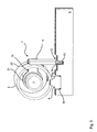
- the FIG. 1 shows in the schematic, three-dimensional representation of a section of a switching device 1 with a locking system.
- the switching device 1 comprises a switching shaft 2, which is technically coupled at its free end with a user operable by a driver manual shift lever.
- the switching shaft 2 is displaceable along the arrow 3 in its axial extent and also arranged in the direction of rotation according to arrow 4 about its own axis pivotally.
- the switching device 1 comprises a switching sleeve 5, which is arranged coaxially with the switching shaft 2 and with this displacement and pivoting, for example, materially bonded, in particular by welding, is connected.
- the shift sleeve 5 carries on its outer side a cam crest 6, which receives a spring-loaded latching cam 7, and one or more shift finger 8, which extends in the radial direction of the shift sleeve 5 and is connected cohesively thereto.
- the switching device For the transmission of switching movements to a manual transmission, not shown, the switching device 1, three shift rails 9, which are aligned parallel to each other and perpendicular to the shift shaft 2. At their switching shaft 2 facing end portions, the shift rails 9 each have a switching mouth 10, which is formed as a rectangular, edge-open recess.
- the shift shaft 2 is displaced along the arrow 3, so that the shift finger 8 is positioned in the shift jaw 10 of a desired shift rail 9.
- the shift finger 8 is pivoted about the shift shaft 2, pushes the selected shift rail 9 in dependence of the pivoting direction in FIG. 2 to the left or to the right, thus entering a desired gear.
- the switching device 1 has a locking device 11.
- the locking device 11 which is designed for example as a stamped and bent part, comprises a locking portion 12, which is formed as a first, planar sheet metal section and engages in the shift rails 9 arranged in offset to the Wegaugru 10 Verriegelungsmäuler 13, wherein this perpendicular to the longitudinal extent of the shift rails 9 can be moved by the switching shaft 2.
- the locking portion 12 has a recess 14 which is adapted in width in the direction of extension of the arrow 3 to the widths of one of the shift rails 9 such that depending on the position of the locking portion 12, one of the shift rails 9 is switchable, whereas the other two shift rails 9 locked are.
- the middle shift rail 9 is switchable, that is, displaceable in its longitudinal extent and the other two shift rails 9 locked by the locking portion 12.
- the locking device 11 has a guide section 15, which is formed as a second, planar sheet metal section, in which a guide groove 16 and a guide channel 16 is introduced.
- a guide pin 17 which is rigidly and / or fixedly connected to the housing 18 or - in other embodiments - with the gear dome housing.
- Guide channel 16 and guide pin 17 define a positive guide for the second sheet metal section and thus for the locking portion 12, so that Although this displaced in the direction of arrow 3, but not in the circumferential direction of the switching shaft 2 according to arrow 4 is pivotable.
- the guide plate 16 carrying the second sheet metal portion and the locking portion 12 supporting the first sheet metal portion form a common, planar and / or unbent and / or undeformed sheet metal section in its surface extension a locking plane, ie a plane in which the locking portion is and is moved, and at the same time defines a coplanar and / or congruent shift plane, ie a sliding plane in which the guide section 15 is located and displaced.
- this two driving leg 19 which extend at right angles from the common sheet metal section formed by the first and second sheet metal section.
- the driving leg 19 engage by two introduced in the shift sleeve 5, extending in the circumferential direction, channel-shaped guide grooves 20 and have at their free end in each case a disc-annular end portion 21, through the free passage opening the shift shaft 2 is freely rotatably threaded.
- the locking device is entrained in an axial displacement of the switching shaft 2 according to arrow 3 on the shift sleeve 5, wherein the driving leg 19 abut against the boundaries of the guide grooves 20 positively and force-transmitting.
- the guide grooves 20 extend so far that the composite formed from shift shaft 2 and shift sleeve 5 is pivotable for a switching movement without taking the locking device 11, so that the locking device 11 is decoupled from the pivotal movement of the shift shaft 2 is arranged ,
- the FIG. 4 shows a second embodiment of a switching device 1 in a cut, three-dimensional representation.
- the switching device 1 has a in the FIG. 4 centrally extending shift shaft 2, which a first shift finger 8 a and axially spaced therefrom a second shift finger 8 b carries.
- the shift fingers 8a and 8b are arranged and configured to intervene in perpendicular to the shift shaft 2 arranged shift rails 9 a, b, c, d.
- the shift rails 9 a, b, c, d each have a shift jaw 10.
- FIG. 4 shows a second embodiment of a switching device 1 in a cut, three-dimensional representation.
- the switching device 1 has a in the FIG. 4 centrally extending shift shaft 2, which a first shift finger 8 a and axially spaced therefrom a second shift finger 8 b carries.
- the shift fingers 8a and 8b are arranged and configured to intervene in perpendicular to the shift shaft 2 arranged shift rails 9
- the shift shaft 2 occupy four preselection positions, so that in a first preset position, the shift rail 9 a, in a second preset position the shift rail 9 b, in a third preset position the shift rail 9 c and in a fourth dial position the shift rail 9 d is selected.
- the switching device 1 For additional guidance of the switching shaft 2, the switching device 1, a shift gate 22, into which engages a link finger 23 depending on the selected position.
- the locking system 1 shows a cam crest 6, in which a locking cam 7 engages.
- a locking device 11 is in the FIG. 4 essentially formed as a planar sheet metal section, which in the region of the two shift rail groups 9 a, c and 9 b, d respectively carries a locking portion 12, wherein each locking portion 12 has a recess 14 which by displacement of the locking device 11 in the axial direction according to arrow 3 in a release position for a selected shift rail 9 a, b, c, d, can be brought.
- a guide portion 15 of the locking device 11 is a portion of the flat sheet metal portion and has two guide pins 24 which are fixed in the guide portion 15 and guided in guide channels 16 which are inserted in a housing-fixed guide plate 25.
- Guide plate 25 and guide channels 16 thus form a housing-side guide member.
- the engagement is realized so that when an axial displacement of the switching shaft 2, the locking device 11 by the shift finger 8 a, b, is guided, whereas at a pivoting of the switching shaft 2 in the direction of rotation according to arrow 4, the gap in the fork of the shift finger 8 a, b, is designed so that the shift finger 8 a, b, can freely pivot without entrainment of the locking device 11.
- the locking element 11 shows in FIG. 4 as an easy-to-manufacture component, which can be produced cost-effectively by a punching process with a subsequent insertion of the guide pins 24.
Claims (15)
- Dispositif de changement de vitesse (1) pour une transmission à changement de vitesse d'un véhicule automobile, comprenant un dispositif de verrouillage (11) avec un arbre de sélection (2) pour la présélection et pour le changement de vitesses dans la transmission à changement de vitesse, comprenant une pluralité de rails de changement de vitesse (9) pour le transfert des couples de changement de vitesse de l'arbre de sélection (2) à la transmission à changement de vitesse,
l'arbre de sélection (2) étant orienté perpendiculairement aux rails de changement de vitesse (9) et étant déplaçable axialement pour la présélection de vitesses et étant disposé de manière à pouvoir pivoter autour de l'axe propre pour le changement de vitesses,
le dispositif de verrouillage (11) présentant une portion de verrouillage (12) pour la libération de l'un des rails de changement de vitesse (9) et pour le verrouillage des autres rails de changement de vitesse et une portion de guidage (15) pour le guidage axial du dispositif de verrouillage (11) sur un organe de guidage fixé au boîtier,
le dispositif de verrouillage (11) étant réalisé et/ou disposé de telle sorte que dans le cas d'un déplacement axial de l'arbre de sélection (2) pour la présélection des vitesses, il soit entraîné en même temps et que dans le cas d'un pivotement de l'arbre de sélection pour le changement de vitesse, il tourne librement,
caractérisé en ce que
la portion de verrouillage (12) est réalisée sous forme de première portion de tôle plane, qui définit dans l'étendue en surface un plan de verrouillage, et en ce qu'entre la portion de guidage (15) et l'organe de guidage en tant que plan de déplacement est défini un plan de guidage, le plan de verrouillage et le plan de guidage étant disposés parallèlement l'un à l'autre du même côté de l'arbre de sélection (2), c'est-à-dire de telle sorte que l'axe propre de l'arbre de sélection (2) ne soit pas disposé entre les plans. - Dispositif de changement de vitesse (1) selon la revendication 1, caractérisé en ce que le plan de verrouillage et le plan de guidage sont disposés de manière coplanaire l'un par rapport à l'autre.
- Dispositif de changement de vitesse (1) selon la revendication 1 ou 2, caractérisé en ce que la portion de guidage (15) présente une deuxième portion de tôle plane, dont l'étendue en surface définit le plan de déplacement.
- Dispositif de changement de vitesse (1) selon la revendication 3, caractérisé en ce que la première et la deuxième portion de tôle plane forment une portion de tôle plane commune.
- Dispositif de changement de vitesse (1) selon l'une quelconque des revendications précédentes, caractérisé en ce que la portion de verrouillage (12) présente un évidement (14) ouvert du côté du bord, dont la largeur est adaptée à la largeur de l'un des rails de changement de vitesse (9) de telle sorte que les autres rails de changement de vitesse soient respectivement bloqués.
- Dispositif de changement de vitesse (1) selon la revendication 5, caractérisé en ce que les rails de changement de vitesse présentent des mors de verrouillage (13), dans lesquels s'engage la portion de verrouillage (12).
- Dispositif de changement de vitesse (1) selon l'une quelconque des revendications précédentes, caractérisé en ce que la portion de guidage (15) ou l'organe de guidage présente un canal de guidage orienté axialement (16) et l'organe de guidage ou la portion de guidage présente un élément de guidage, en particulier une goupille de guidage (17), qui est guidée à travers le canal de guidage (16) dans la direction axiale.
- Dispositif de changement de vitesse (1) selon l'une quelconque des revendications précédentes, caractérisé en ce que le dispositif de verrouillage (11) présente une portion d'entraînement (19, 26), par le biais de laquelle le dispositif de verrouillage (11) est accouplé à un organe d'entraînement (5, 8a, b) de l'arbre de sélection (2) pour l'entraînement axial et, dans le cadre du pivotement de présélection, pour le déplacement en roue libre azimutal.
- Dispositif de changement de vitesse (1) selon la revendication 8, caractérisé en ce que l'organe d'entraînement est réalisé sous forme de doigt de sélection (8a, b), qui vient en prise dans un évidement (26) du côté du bord de la portion d'entraînement du dispositif de verrouillage (11).
- Dispositif de changement de vitesse (1) selon la revendication 9, caractérisé en ce que le doigt de sélection (8a, b) présente du côté de l'extrémité une fourche, dont l'espace de fourche libre est dimensionné de telle sorte que l'arbre de sélection (2) puisse pivoter librement dans le cadre du pivotement de présélection dans la direction périphérique par rapport au dispositif de verrouillage (11).
- Dispositif de changement de vitesse (1) selon la revendication 8, caractérisé en ce que l'organe d'entraînement est réalisé sous forme de manchon de sélection (5).
- Dispositif de changement de vitesse (1) selon la revendication 11, caractérisé en ce que la portion d'entraînement est réalisée sous forme d'au moins une branche d'entraînement (19), qui s'étend dans la direction radiale.
- Dispositif de changement de vitesse (1) selon la revendication 12, caractérisé en ce que la branche d'entraînement (19) est enfilée de manière pivotante sur l'arbre de sélection (2).
- Dispositif de changement de vitesse (1) selon la revendication 12 ou 13, caractérisé en ce que le manchon de sélection (5) présente une rainure d'entraînement (20) s'étendant dans la direction périphérique, pour réaliser, entraîner axialement et/ou libérer le mouvement azimutal de la branche d'entraînement (19).
- Dispositif de changement de vitesse (1) selon l'une quelconque des revendications 12 à 14, caractérisé en ce que la branche d'entraînement (19) est disposée à angle droit par rapport à la première, deuxième et/ou troisième région de tôle.
Applications Claiming Priority (2)
| Application Number | Priority Date | Filing Date | Title |
|---|---|---|---|
| DE102007033384 | 2007-07-18 | ||
| PCT/EP2008/057102 WO2009010341A1 (fr) | 2007-07-18 | 2008-06-06 | Dispositif de passage des vitesses pour une boîte de vitesses d'un véhicule motorisé comportant un dispositif de verrouillage |
Publications (2)
| Publication Number | Publication Date |
|---|---|
| EP2179200A1 EP2179200A1 (fr) | 2010-04-28 |
| EP2179200B1 true EP2179200B1 (fr) | 2011-09-14 |
Family
ID=39761056
Family Applications (1)
| Application Number | Title | Priority Date | Filing Date |
|---|---|---|---|
| EP08760672A Active EP2179200B1 (fr) | 2007-07-18 | 2008-06-06 | Dispositif de passage des vitesses pour une boîte de vitesses d'un véhicule motorisé comportant un dispositif de verrouillage |
Country Status (4)
| Country | Link |
|---|---|
| EP (1) | EP2179200B1 (fr) |
| CN (1) | CN101842619B (fr) |
| AT (1) | ATE524676T1 (fr) |
| WO (1) | WO2009010341A1 (fr) |
Cited By (1)
| Publication number | Priority date | Publication date | Assignee | Title |
|---|---|---|---|---|
| DE102014220429A1 (de) | 2014-10-09 | 2016-04-28 | Zf Friedrichshafen Ag | Schalteinheit für ein automatisiertes Fahrzeuggetriebe mit einer Mehrzahl an Teilgetrieben mit Verriegelungsvorrichtung |
Families Citing this family (4)
| Publication number | Priority date | Publication date | Assignee | Title |
|---|---|---|---|---|
| DE102008029262B4 (de) * | 2008-06-19 | 2020-03-26 | Schaeffler Technologies AG & Co. KG | Verriegelungsvorrichtung zur Verriegelung von Schaltschienen eines Getriebes |
| WO2014053135A1 (fr) * | 2012-10-01 | 2014-04-10 | Schaeffler Technologies AG & Co. KG | Dispositif de commande de vitesses pour une boîte de vitesses à engrenages d'un véhicule à moteur |
| DE102014209165A1 (de) * | 2014-05-15 | 2015-11-19 | Zf Friedrichshafen Ag | Schaltvorrichtung sowie Kraftfahrzeug |
| CN107631027B (zh) * | 2017-11-02 | 2019-06-21 | 苏州东风精冲工程有限公司 | 一种倒档拨叉偏置式驱动锁止结构 |
Family Cites Families (7)
| Publication number | Priority date | Publication date | Assignee | Title |
|---|---|---|---|---|
| DE3011131A1 (de) * | 1980-03-22 | 1981-10-01 | Volkswagenwerk Ag, 3180 Wolfsburg | Schaltvorrichtung |
| DE3913269A1 (de) | 1989-04-22 | 1990-10-31 | Ford Werke Ag | Schaltvorrichtung fuer wechselgetriebe von kraftfahrzeugen |
| DE4443523C1 (de) * | 1994-12-07 | 1996-05-02 | Daimler Benz Ag | Schaltvorrichtung für ein Zahnräderwechselgetriebe eines Kraftfahrzeuges |
| DE19511510C1 (de) * | 1995-03-29 | 1996-07-04 | Daimler Benz Ag | Nockenscheiben-Anordnung einer Schaltkulisse für eine Schaltvorrichtung eines Zahnräderwechselgetriebes |
| TW536597B (en) * | 2001-06-29 | 2003-06-11 | Honda Motor Co Ltd | Changing system in manual transmission |
| FR2852073B1 (fr) * | 2003-03-06 | 2005-04-01 | Peugeot Citroen Automobiles Sa | Commande interne de boite de vitesses pilotee |
| JP4235502B2 (ja) * | 2003-07-09 | 2009-03-11 | 本田技研工業株式会社 | 手動変速機のシフトチェンジ装置 |
-
2008
- 2008-06-06 WO PCT/EP2008/057102 patent/WO2009010341A1/fr active Application Filing
- 2008-06-06 CN CN200880025135.6A patent/CN101842619B/zh active Active
- 2008-06-06 AT AT08760672T patent/ATE524676T1/de active
- 2008-06-06 EP EP08760672A patent/EP2179200B1/fr active Active
Cited By (1)
| Publication number | Priority date | Publication date | Assignee | Title |
|---|---|---|---|---|
| DE102014220429A1 (de) | 2014-10-09 | 2016-04-28 | Zf Friedrichshafen Ag | Schalteinheit für ein automatisiertes Fahrzeuggetriebe mit einer Mehrzahl an Teilgetrieben mit Verriegelungsvorrichtung |
Also Published As
| Publication number | Publication date |
|---|---|
| ATE524676T1 (de) | 2011-09-15 |
| EP2179200A1 (fr) | 2010-04-28 |
| CN101842619B (zh) | 2013-03-27 |
| WO2009010341A1 (fr) | 2009-01-22 |
| CN101842619A (zh) | 2010-09-22 |
Similar Documents
| Publication | Publication Date | Title |
|---|---|---|
| DE2633730B2 (de) | Mechanische Schalteinrichtung für ein Zahnräderwechselgetriebe | |
| DE10316163A1 (de) | Mehrstufiges Schaltgetriebe für eine Brennkraftmaschine | |
| DE19805924A1 (de) | Getriebe | |
| EP2288826B1 (fr) | PROCÉDÉ DE FABRICATION Du DISPOSITIF DE DOIGT DE CHANGEMENT DE VITESSES | |
| EP2179200B1 (fr) | Dispositif de passage des vitesses pour une boîte de vitesses d'un véhicule motorisé comportant un dispositif de verrouillage | |
| EP1379797B1 (fr) | Dispositif de changement de vitesses a un arbre | |
| DE19901056A1 (de) | Schaltvorrichtung mit Einwellenschaltung | |
| DE10203633A1 (de) | Schaltvorrichtung eines Getriebes | |
| EP2529133B1 (fr) | Dispositif de protection de changement de vitesses d'une boîte de vitesses à rapports multiples | |
| DE2653035C3 (de) | Schaltvorrichtung für ein Kraftfahrzeugwechselgetriebe | |
| DE60014277T2 (de) | Schaltgabel für Getriebe eines Kraftfahrzeuges | |
| DE112005001381B4 (de) | Gangschaltsystem | |
| EP1711727B1 (fr) | Systeme de changement de vitesses | |
| DE19540522C1 (de) | Schaltvorrichtung für ein Schaltgetriebe zur Vermeidung des unbeabsichtigten Einlegens des Rückwärtsganges | |
| DE10045266C2 (de) | Schaltvorrichtung zum Betätigen eines mehrstufigen Schaltgetriebes | |
| DE102014115371B4 (de) | Schaltanordnung für ein Kraftfahrzeuggetriebe und Schaltverfahren | |
| WO2009112343A1 (fr) | Dispositif d'actionnement pour l'actionnement d'au moins un dispositif de couplage et procédé de montage et de démontage de celui-ci. | |
| DE102006061607A1 (de) | Schaltvorrichtung eines manuell schaltbaren KFZ-Getriebes | |
| EP1680612B1 (fr) | Dispositif de passage des rapports destine a une boite a plusieurs rapports | |
| DE102014215527A1 (de) | Schaltwellenvorrichtung für ein Schaltgetriebe sowie Fahrzeug mit der Schaltwellenvorrichtung | |
| EP1310707B1 (fr) | Dispositif de changement de vitesses et méthode de mouvement et guidage de fourchettes dans une transmission à changement de vitesses | |
| EP1245872B1 (fr) | Dispositif de commande de boítes de vitesses, notamment pour véhicule automobile | |
| DE4441967A1 (de) | Schaltvorrichtung für mehrgängiges Wechselgetriebe | |
| EP1440259B1 (fr) | Dispositif de commutation pour changement de vitesse manuel | |
| DE102006057462A1 (de) | Schaltvorrichtung |
Legal Events
| Date | Code | Title | Description |
|---|---|---|---|
| PUAI | Public reference made under article 153(3) epc to a published international application that has entered the european phase |
Free format text: ORIGINAL CODE: 0009012 |
|
| 17P | Request for examination filed |
Effective date: 20100218 |
|
| AK | Designated contracting states |
Kind code of ref document: A1 Designated state(s): AT BE BG CH CY CZ DE DK EE ES FI FR GB GR HR HU IE IS IT LI LT LU LV MC MT NL NO PL PT RO SE SI SK TR |
|
| AX | Request for extension of the european patent |
Extension state: AL BA MK RS |
|
| 17Q | First examination report despatched |
Effective date: 20100802 |
|
| DAX | Request for extension of the european patent (deleted) | ||
| GRAP | Despatch of communication of intention to grant a patent |
Free format text: ORIGINAL CODE: EPIDOSNIGR1 |
|
| GRAS | Grant fee paid |
Free format text: ORIGINAL CODE: EPIDOSNIGR3 |
|
| GRAA | (expected) grant |
Free format text: ORIGINAL CODE: 0009210 |
|
| RAP1 | Party data changed (applicant data changed or rights of an application transferred) |
Owner name: SCHAEFFLER TECHNOLOGIES GMBH & CO. KG |
|
| AK | Designated contracting states |
Kind code of ref document: B1 Designated state(s): AT BE BG CH CY CZ DE DK EE ES FI FR GB GR HR HU IE IS IT LI LT LU LV MC MT NL NO PL PT RO SE SI SK TR |
|
| REG | Reference to a national code |
Ref country code: GB Ref legal event code: FG4D Free format text: NOT ENGLISH |
|
| REG | Reference to a national code |
Ref country code: CH Ref legal event code: EP |
|
| REG | Reference to a national code |
Ref country code: IE Ref legal event code: FG4D Free format text: LANGUAGE OF EP DOCUMENT: GERMAN |
|
| REG | Reference to a national code |
Ref country code: DE Ref legal event code: R096 Ref document number: 502008004883 Country of ref document: DE Effective date: 20111117 |
|
| REG | Reference to a national code |
Ref country code: NL Ref legal event code: VDEP Effective date: 20110914 |
|
| PG25 | Lapsed in a contracting state [announced via postgrant information from national office to epo] |
Ref country code: SE Free format text: LAPSE BECAUSE OF FAILURE TO SUBMIT A TRANSLATION OF THE DESCRIPTION OR TO PAY THE FEE WITHIN THE PRESCRIBED TIME-LIMIT Effective date: 20110914 Ref country code: NO Free format text: LAPSE BECAUSE OF FAILURE TO SUBMIT A TRANSLATION OF THE DESCRIPTION OR TO PAY THE FEE WITHIN THE PRESCRIBED TIME-LIMIT Effective date: 20111214 Ref country code: FI Free format text: LAPSE BECAUSE OF FAILURE TO SUBMIT A TRANSLATION OF THE DESCRIPTION OR TO PAY THE FEE WITHIN THE PRESCRIBED TIME-LIMIT Effective date: 20110914 Ref country code: LT Free format text: LAPSE BECAUSE OF FAILURE TO SUBMIT A TRANSLATION OF THE DESCRIPTION OR TO PAY THE FEE WITHIN THE PRESCRIBED TIME-LIMIT Effective date: 20110914 Ref country code: HR Free format text: LAPSE BECAUSE OF FAILURE TO SUBMIT A TRANSLATION OF THE DESCRIPTION OR TO PAY THE FEE WITHIN THE PRESCRIBED TIME-LIMIT Effective date: 20110914 |
|
| LTIE | Lt: invalidation of european patent or patent extension |
Effective date: 20110914 |
|
| PG25 | Lapsed in a contracting state [announced via postgrant information from national office to epo] |
Ref country code: CY Free format text: LAPSE BECAUSE OF FAILURE TO SUBMIT A TRANSLATION OF THE DESCRIPTION OR TO PAY THE FEE WITHIN THE PRESCRIBED TIME-LIMIT Effective date: 20110914 Ref country code: SI Free format text: LAPSE BECAUSE OF FAILURE TO SUBMIT A TRANSLATION OF THE DESCRIPTION OR TO PAY THE FEE WITHIN THE PRESCRIBED TIME-LIMIT Effective date: 20110914 Ref country code: LV Free format text: LAPSE BECAUSE OF FAILURE TO SUBMIT A TRANSLATION OF THE DESCRIPTION OR TO PAY THE FEE WITHIN THE PRESCRIBED TIME-LIMIT Effective date: 20110914 Ref country code: GR Free format text: LAPSE BECAUSE OF FAILURE TO SUBMIT A TRANSLATION OF THE DESCRIPTION OR TO PAY THE FEE WITHIN THE PRESCRIBED TIME-LIMIT Effective date: 20111215 |
|
| RAP2 | Party data changed (patent owner data changed or rights of a patent transferred) |
Owner name: SCHAEFFLER TECHNOLOGIES AG & CO. KG |
|
| REG | Reference to a national code |
Ref country code: CH Ref legal event code: PFA Owner name: SCHAEFFLER TECHNOLOGIES AG & CO. KG Free format text: SCHAEFFLER TECHNOLOGIES GMBH & CO. KG#INDUSTRIESTRASSE 1-3#91074 HERZOGENAURACH (DE) -TRANSFER TO- SCHAEFFLER TECHNOLOGIES AG & CO. KG#INDUSTRIESTRASSE 1-3#91074 HERZOGENAURACH (DE) |
|
| REG | Reference to a national code |
Ref country code: IE Ref legal event code: FD4D |
|
| PG25 | Lapsed in a contracting state [announced via postgrant information from national office to epo] |
Ref country code: IS Free format text: LAPSE BECAUSE OF FAILURE TO SUBMIT A TRANSLATION OF THE DESCRIPTION OR TO PAY THE FEE WITHIN THE PRESCRIBED TIME-LIMIT Effective date: 20120114 Ref country code: CZ Free format text: LAPSE BECAUSE OF FAILURE TO SUBMIT A TRANSLATION OF THE DESCRIPTION OR TO PAY THE FEE WITHIN THE PRESCRIBED TIME-LIMIT Effective date: 20110914 Ref country code: SK Free format text: LAPSE BECAUSE OF FAILURE TO SUBMIT A TRANSLATION OF THE DESCRIPTION OR TO PAY THE FEE WITHIN THE PRESCRIBED TIME-LIMIT Effective date: 20110914 Ref country code: IE Free format text: LAPSE BECAUSE OF FAILURE TO SUBMIT A TRANSLATION OF THE DESCRIPTION OR TO PAY THE FEE WITHIN THE PRESCRIBED TIME-LIMIT Effective date: 20110914 |
|
| PG25 | Lapsed in a contracting state [announced via postgrant information from national office to epo] |
Ref country code: EE Free format text: LAPSE BECAUSE OF FAILURE TO SUBMIT A TRANSLATION OF THE DESCRIPTION OR TO PAY THE FEE WITHIN THE PRESCRIBED TIME-LIMIT Effective date: 20110914 Ref country code: PL Free format text: LAPSE BECAUSE OF FAILURE TO SUBMIT A TRANSLATION OF THE DESCRIPTION OR TO PAY THE FEE WITHIN THE PRESCRIBED TIME-LIMIT Effective date: 20110914 Ref country code: RO Free format text: LAPSE BECAUSE OF FAILURE TO SUBMIT A TRANSLATION OF THE DESCRIPTION OR TO PAY THE FEE WITHIN THE PRESCRIBED TIME-LIMIT Effective date: 20110914 Ref country code: NL Free format text: LAPSE BECAUSE OF FAILURE TO SUBMIT A TRANSLATION OF THE DESCRIPTION OR TO PAY THE FEE WITHIN THE PRESCRIBED TIME-LIMIT Effective date: 20110914 Ref country code: PT Free format text: LAPSE BECAUSE OF FAILURE TO SUBMIT A TRANSLATION OF THE DESCRIPTION OR TO PAY THE FEE WITHIN THE PRESCRIBED TIME-LIMIT Effective date: 20120116 |
|
| REG | Reference to a national code |
Ref country code: DE Ref legal event code: R097 Ref document number: 502008004883 Country of ref document: DE |
|
| PLBE | No opposition filed within time limit |
Free format text: ORIGINAL CODE: 0009261 |
|
| STAA | Information on the status of an ep patent application or granted ep patent |
Free format text: STATUS: NO OPPOSITION FILED WITHIN TIME LIMIT |
|
| PG25 | Lapsed in a contracting state [announced via postgrant information from national office to epo] |
Ref country code: DK Free format text: LAPSE BECAUSE OF FAILURE TO SUBMIT A TRANSLATION OF THE DESCRIPTION OR TO PAY THE FEE WITHIN THE PRESCRIBED TIME-LIMIT Effective date: 20110914 |
|
| 26N | No opposition filed |
Effective date: 20120615 |
|
| REG | Reference to a national code |
Ref country code: DE Ref legal event code: R097 Ref document number: 502008004883 Country of ref document: DE Effective date: 20120615 |
|
| REG | Reference to a national code |
Ref country code: DE Ref legal event code: R081 Ref document number: 502008004883 Country of ref document: DE Owner name: SCHAEFFLER TECHNOLOGIES AG & CO. KG, DE Free format text: FORMER OWNER: SCHAEFFLER TECHNOLOGIES GMBH & CO. KG, 91074 HERZOGENAURACH, DE Effective date: 20120828 Ref country code: DE Ref legal event code: R081 Ref document number: 502008004883 Country of ref document: DE Owner name: SCHAEFFLER TECHNOLOGIES GMBH & CO. KG, DE Free format text: FORMER OWNER: SCHAEFFLER TECHNOLOGIES GMBH & CO. KG, 91074 HERZOGENAURACH, DE Effective date: 20120828 |
|
| BERE | Be: lapsed |
Owner name: SCHAEFFLER TECHNOLOGIES G.M.B.H. & CO. KG Effective date: 20120630 |
|
| PG25 | Lapsed in a contracting state [announced via postgrant information from national office to epo] |
Ref country code: MC Free format text: LAPSE BECAUSE OF NON-PAYMENT OF DUE FEES Effective date: 20120630 |
|
| REG | Reference to a national code |
Ref country code: CH Ref legal event code: PL |
|
| REG | Reference to a national code |
Ref country code: CH Ref legal event code: PL |
|
| GBPC | Gb: european patent ceased through non-payment of renewal fee |
Effective date: 20120606 |
|
| PG25 | Lapsed in a contracting state [announced via postgrant information from national office to epo] |
Ref country code: CH Free format text: LAPSE BECAUSE OF NON-PAYMENT OF DUE FEES Effective date: 20120630 Ref country code: ES Free format text: LAPSE BECAUSE OF FAILURE TO SUBMIT A TRANSLATION OF THE DESCRIPTION OR TO PAY THE FEE WITHIN THE PRESCRIBED TIME-LIMIT Effective date: 20111225 Ref country code: LI Free format text: LAPSE BECAUSE OF NON-PAYMENT OF DUE FEES Effective date: 20120630 Ref country code: BE Free format text: LAPSE BECAUSE OF NON-PAYMENT OF DUE FEES Effective date: 20120630 Ref country code: GB Free format text: LAPSE BECAUSE OF NON-PAYMENT OF DUE FEES Effective date: 20120606 |
|
| PG25 | Lapsed in a contracting state [announced via postgrant information from national office to epo] |
Ref country code: BG Free format text: LAPSE BECAUSE OF FAILURE TO SUBMIT A TRANSLATION OF THE DESCRIPTION OR TO PAY THE FEE WITHIN THE PRESCRIBED TIME-LIMIT Effective date: 20111214 |
|
| PG25 | Lapsed in a contracting state [announced via postgrant information from national office to epo] |
Ref country code: MT Free format text: LAPSE BECAUSE OF FAILURE TO SUBMIT A TRANSLATION OF THE DESCRIPTION OR TO PAY THE FEE WITHIN THE PRESCRIBED TIME-LIMIT Effective date: 20110914 |
|
| REG | Reference to a national code |
Ref country code: DE Ref legal event code: R081 Ref document number: 502008004883 Country of ref document: DE Owner name: SCHAEFFLER TECHNOLOGIES GMBH & CO. KG, DE Free format text: FORMER OWNER: SCHAEFFLER TECHNOLOGIES AG & CO. KG, 91074 HERZOGENAURACH, DE Effective date: 20140212 Ref country code: DE Ref legal event code: R081 Ref document number: 502008004883 Country of ref document: DE Owner name: SCHAEFFLER TECHNOLOGIES AG CO. KG, DE Free format text: FORMER OWNER: SCHAEFFLER TECHNOLOGIES AG CO. KG, 91074 HERZOGENAURACH, DE Effective date: 20140212 Ref country code: DE Ref legal event code: R081 Ref document number: 502008004883 Country of ref document: DE Owner name: SCHAEFFLER TECHNOLOGIES AG & CO. KG, DE Free format text: FORMER OWNER: SCHAEFFLER TECHNOLOGIES AG & CO. KG, 91074 HERZOGENAURACH, DE Effective date: 20140212 |
|
| PG25 | Lapsed in a contracting state [announced via postgrant information from national office to epo] |
Ref country code: TR Free format text: LAPSE BECAUSE OF FAILURE TO SUBMIT A TRANSLATION OF THE DESCRIPTION OR TO PAY THE FEE WITHIN THE PRESCRIBED TIME-LIMIT Effective date: 20110914 |
|
| PG25 | Lapsed in a contracting state [announced via postgrant information from national office to epo] |
Ref country code: LU Free format text: LAPSE BECAUSE OF NON-PAYMENT OF DUE FEES Effective date: 20120606 |
|
| PG25 | Lapsed in a contracting state [announced via postgrant information from national office to epo] |
Ref country code: HU Free format text: LAPSE BECAUSE OF FAILURE TO SUBMIT A TRANSLATION OF THE DESCRIPTION OR TO PAY THE FEE WITHIN THE PRESCRIBED TIME-LIMIT Effective date: 20080606 |
|
| REG | Reference to a national code |
Ref country code: AT Ref legal event code: MM01 Ref document number: 524676 Country of ref document: AT Kind code of ref document: T Effective date: 20130606 |
|
| PG25 | Lapsed in a contracting state [announced via postgrant information from national office to epo] |
Ref country code: AT Free format text: LAPSE BECAUSE OF NON-PAYMENT OF DUE FEES Effective date: 20130606 |
|
| REG | Reference to a national code |
Ref country code: DE Ref legal event code: R081 Ref document number: 502008004883 Country of ref document: DE Owner name: SCHAEFFLER TECHNOLOGIES AG & CO. KG, DE Free format text: FORMER OWNER: SCHAEFFLER TECHNOLOGIES GMBH & CO. KG, 91074 HERZOGENAURACH, DE Effective date: 20150127 |
|
| REG | Reference to a national code |
Ref country code: FR Ref legal event code: PLFP Year of fee payment: 8 |
|
| REG | Reference to a national code |
Ref country code: FR Ref legal event code: PLFP Year of fee payment: 9 |
|
| REG | Reference to a national code |
Ref country code: FR Ref legal event code: PLFP Year of fee payment: 10 |
|
| REG | Reference to a national code |
Ref country code: FR Ref legal event code: PLFP Year of fee payment: 11 |
|
| P01 | Opt-out of the competence of the unified patent court (upc) registered |
Effective date: 20230522 |
|
| PGFP | Annual fee paid to national office [announced via postgrant information from national office to epo] |
Ref country code: FR Payment date: 20230620 Year of fee payment: 16 |
|
| PGFP | Annual fee paid to national office [announced via postgrant information from national office to epo] |
Ref country code: IT Payment date: 20230623 Year of fee payment: 16 |
|
| PGFP | Annual fee paid to national office [announced via postgrant information from national office to epo] |
Ref country code: DE Payment date: 20230821 Year of fee payment: 16 |