EP2179200B1 - Shifting device for a transmission of a motor vehicle having a locking device - Google Patents
Shifting device for a transmission of a motor vehicle having a locking device Download PDFInfo
- Publication number
- EP2179200B1 EP2179200B1 EP08760672A EP08760672A EP2179200B1 EP 2179200 B1 EP2179200 B1 EP 2179200B1 EP 08760672 A EP08760672 A EP 08760672A EP 08760672 A EP08760672 A EP 08760672A EP 2179200 B1 EP2179200 B1 EP 2179200B1
- Authority
- EP
- European Patent Office
- Prior art keywords
- shift
- locking
- guide
- section
- shaft
- Prior art date
- Legal status (The legal status is an assumption and is not a legal conclusion. Google has not performed a legal analysis and makes no representation as to the accuracy of the status listed.)
- Active
Links
- 230000005540 biological transmission Effects 0.000 title abstract description 18
- 239000002184 metal Substances 0.000 claims abstract description 24
- 238000006073 displacement reaction Methods 0.000 abstract description 10
- 238000004519 manufacturing process Methods 0.000 description 5
- 238000003780 insertion Methods 0.000 description 3
- 230000037431 insertion Effects 0.000 description 3
- 230000008878 coupling Effects 0.000 description 2
- 238000010168 coupling process Methods 0.000 description 2
- 238000005859 coupling reaction Methods 0.000 description 2
- 238000000034 method Methods 0.000 description 2
- 206010044684 Trismus Diseases 0.000 description 1
- 238000005452 bending Methods 0.000 description 1
- 239000002131 composite material Substances 0.000 description 1
- 230000001419 dependent effect Effects 0.000 description 1
- 230000000694 effects Effects 0.000 description 1
- 238000004080 punching Methods 0.000 description 1
- 238000000926 separation method Methods 0.000 description 1
- 230000000087 stabilizing effect Effects 0.000 description 1
- 238000003466 welding Methods 0.000 description 1
Images


Classifications
-
- F—MECHANICAL ENGINEERING; LIGHTING; HEATING; WEAPONS; BLASTING
- F16—ENGINEERING ELEMENTS AND UNITS; GENERAL MEASURES FOR PRODUCING AND MAINTAINING EFFECTIVE FUNCTIONING OF MACHINES OR INSTALLATIONS; THERMAL INSULATION IN GENERAL
- F16H—GEARING
- F16H63/00—Control outputs from the control unit to change-speed- or reversing-gearings for conveying rotary motion or to other devices than the final output mechanism
- F16H63/02—Final output mechanisms therefor; Actuating means for the final output mechanisms
- F16H63/30—Constructional features of the final output mechanisms
- F16H63/34—Locking or disabling mechanisms
- F16H63/3408—Locking or disabling mechanisms the locking mechanism being moved by the final actuating mechanism
-
- F—MECHANICAL ENGINEERING; LIGHTING; HEATING; WEAPONS; BLASTING
- F16—ENGINEERING ELEMENTS AND UNITS; GENERAL MEASURES FOR PRODUCING AND MAINTAINING EFFECTIVE FUNCTIONING OF MACHINES OR INSTALLATIONS; THERMAL INSULATION IN GENERAL
- F16H—GEARING
- F16H63/00—Control outputs from the control unit to change-speed- or reversing-gearings for conveying rotary motion or to other devices than the final output mechanism
- F16H63/02—Final output mechanisms therefor; Actuating means for the final output mechanisms
- F16H63/08—Multiple final output mechanisms being moved by a single common final actuating mechanism
- F16H63/20—Multiple final output mechanisms being moved by a single common final actuating mechanism with preselection and subsequent movement of each final output mechanism by movement of the final actuating mechanism in two different ways, e.g. guided by a shift gate
-
- F—MECHANICAL ENGINEERING; LIGHTING; HEATING; WEAPONS; BLASTING
- F16—ENGINEERING ELEMENTS AND UNITS; GENERAL MEASURES FOR PRODUCING AND MAINTAINING EFFECTIVE FUNCTIONING OF MACHINES OR INSTALLATIONS; THERMAL INSULATION IN GENERAL
- F16H—GEARING
- F16H63/00—Control outputs from the control unit to change-speed- or reversing-gearings for conveying rotary motion or to other devices than the final output mechanism
- F16H63/02—Final output mechanisms therefor; Actuating means for the final output mechanisms
- F16H63/30—Constructional features of the final output mechanisms
- F16H63/38—Detents
Definitions
- the invention relates to a switching device for a manual transmission of a motor vehicle with a locking device, with a selector shaft for preselection and for shifting gears in the transmission, with a plurality of shift rails for transmitting the switching torque from the shift shaft to the transmission, wherein the shift shaft perpendicular to the Gear shift rails is aligned and for the selection of gears axially displaceable and pivotally arranged for shifting gears about its own axis, wherein the locking device comprises a locking portion for releasing one of the shift rails and for locking the other shift rails and a guide portion for axially guiding the locking device to a housing Having guide member, wherein the locking device is formed and / or arranged so that they entrained in an axial displacement of the shift shaft for preselection of the gears and at a pivoting the shift axle freewheeling for shifting the gears.
- a problem in particular with a manual shift of gears is when incorrectly not one of the two gears of the desired shift rail is inserted, but "switched diagonally", so that a gear of one of the other shift rails is switched. Such a "connection” leads to the insertion of a wrong gear, so that in the worst case the speed and direction of rotation of the gearbox and drive motor do not match and unexpected driving situations or even damage to the gearbox or the drive motor can occur.
- locking systems are known, which are arranged and formed between the shift shaft and gearbox that locks the non-selected shift rails and only the selected shift rail is released for a switching operation.
- the locking system thus ensures that the driver can insert only one gear in the selected shift gate or the selected shift rail by a switching movement.
- Such a locking system is for example from the document DE 30 111 31 A1 known, which relates to a switching device for a mechanical gear change gearbox of motor vehicles.
- a Heidelberggasseninfolmony the shift shaft with respect to the achievement of certain shift gates limiting locking device is disclosed.
- This locking device is designed as a locking plate, which is threaded over two legs on the shift shaft, wherein the locking plate is carried by means of an annular collar-shaped shoulder between the two legs in the axial adjustment of the shift shaft. A rotation of the locking plate is prevented by engagement of a fixed to a transmission housing locking screw which engages in an upper side of the locking plate.
- the publication DE 39 132 69 A1 which probably forms the closest prior art, relates to a switching device for gearboxes of motor vehicles, which also has a switching shaft for transmitting selection and switching torques. Also, this switching device shows a locking plate, which is entrained by a collar of a shift finger in the axial direction, whereas the shift finger or the shift shaft is rotatable in the circumferential direction relative to the locking plate. Likewise, this locking plate is held against rotation via a bolt / slot connection. The bolt / slot connection is arranged in an axial plan view of the switching device at a 90 ° angle relative to the locking region.
- the generic DE 44 43 523 C1 discloses a switching arrangement with a plurality of shift rails, which are actuated by a shift finger.
- the shift finger is flanked by locking cams on both sides. These locking cams allow the operation of a single shift rod by the shift finger.
- the corresponding to the locking cam guide is arranged on the opposite side of the shift shaft.
- the invention has for its object to provide a switching device with locking device for locking shift rails for a manual transmission of motor vehicles, which is reliable and inexpensive.
- a switching device with locking device for locking shift rails for a manual transmission of motor vehicles wherein the transmission is preferably designed as a mechanical, multi-speed change-speed gearbox.
- components of the switching device include a switching shaft, which is preferably actuated via a manual shift lever and which for preselection and arranged and / or formed for shifting gears in the manual transmission.
- a plurality of shift rails preferably three shift rails for switching six gears is provided.
- a corresponding number of shift rails for shifting a different number of gears can be realized.
- the shift shaft - in particular in a plan view in the radial direction of the shift shaft - aligned perpendicular or substantially perpendicular to the shift rails.
- the switching shaft is axially displaceable for the selection of gears or shift rails along its own axis and pivotally arranged for shifting gears about its own axis.
- the shift shaft on a shift finger which can be moved by an axial displacement of the shift shaft between the shift rails and shifts a selected shift rail in its longitudinal extent by pivoting the shift shaft about its own axis to engage the appropriate gear.
- the locking system comprises a one- or multi-part locking device, which shows at least two functional areas:
- a functional area relates to a locking portion which releases one of the shift rails in a selected position and locks the other shift rails at the same time. Changing the preselection also changes the released shift rail.
- Another functional area relates to a guide portion, which is designed for axial guidance, in particular in the axial extent of the switching shaft, the locking device together with a housing-fixed guide member.
- the guide member to a Wegdomgetude which receives the shift shaft and the shift rails, at least in sections, and / or a transmission housing rigidly and / or stationary.
- the axial guide is preferably formed so that the locking device is guided against rotation in the circumferential direction about the shift shaft.
- the locking device is designed and / or arranged so that it is carried on an axial displacement of the shift shaft for preselection of the gears to - as already explained - release one of the shift rails and lock the other, and at a pivoting of the shift axis for insertion the gears, however, freewheeled and mechanically decoupled from the pivotal movement of the shift shaft.
- the locking portion is formed as a first planar sheet metal portion defining a locking plane in surface extension.
- a flat sliding and / or displacement plane which is defined as a management level.
- Locking section and guide section are preferably arranged offset to one another in the axial direction of the switching shaft and / or positioned parallel and / or congruent with one another in axial plan view and / or overlapping.
- the locking plane and the guide plane are arranged coplanar to each other, wherein the two planes coincide.
- a consideration of the invention is that the known from the prior art locking systems constructed with locking plates mechanically complicated and are particularly expensive to manufacture and assembly. This is not least because the locking areas and the guide areas of the known locking plates are arranged relative to the switching shaft opposite or at a 90 ° angle to each other. This arrangement means that the locking plates must be realized as a complex 3-D structure whose low-tolerance manufacturing and assembly is associated with a lot of effort.
- the invention proposes the locking portion and the guide portion on a common side of the To arrange switching shaft, resulting in a manufacturing simplification.
- the guide section of the guide element has a second flat sheet metal section whose surface extension defines the sliding plane.
- locking portion and guide portion are each mitgestaltet by a flat sheet metal portion, wherein the planes defined by the sheet metal sections are arranged parallel to each other and / or coplanar.
- first and second planar sheet metal sections form a common, flat sheet metal section.
- the production of the locking device is particularly simple, since the locking section and guide section by a simple separation process, for example, by a punched, can be produced. In particular, no forming steps are necessary in the area of said two sections.
- the locking device in the region of said two sections is inexpensive and manufacturable with high accuracy.
- the locking portion has a recess open at the edge, which is formed for example in the form of a rectangle whose width is adapted to the width of one of the shift rails such that in each case the other shift rails are locked.
- the recess thus forms a passage area for exactly one shift rail.
- the shift rails on locking mouths in which engages the locking portion.
- the locking mouths also have a preferably rectangular cross-section in a lateral plan view.
- either the guide portion or the guide member comprise an axially, in particular in the axial extent of the switching shaft, aligned guide channel, whereas the respective partner, so the guide member or the guide portion, a guide element, in particular a guide pin which is guided by the guide channel in the axial direction.
- the longitudinal extent of the guide element is arranged so that it is arranged in an axial plan view of the switching shaft perpendicular to the shift shaft, but this does not intersect.
- the locking device For mechanical coupling, the locking device and the switching shaft, the locking device has a driving portion and the switching shaft on a driving member, which are designed such that the locking device of the shift shaft in an axial movement of the shift shaft taken at a pivotal movement of the shift shaft, at least in the context of pre-selection , is uncoupled or runs free.
- This functionality allows the locking device is moved in a preselection of a shift rail to the next shift rail, it is not moved in a switching movement of the shift shaft, however.
- the entrainment member is designed as a shift finger, which engages in an edge-open recess of the driving portion of the locking device.
- the locking device is displaced by the shift finger.
- the shift finger has a fork at its end whose free fork space is dimensioned in the circumferential direction of the shift shaft such that the shift shaft can pivot freely in the azimuthal direction relative to the locking device in the context of the pre-selection pivoting.
- the driving member is formed as a switching sleeve on which preferably at least one shift finger and / or a cam comb is or are arranged.
- the driving portion is formed as at least one driving leg, which extends in the radial direction to the switching shaft.
- the driving leg is on the switching shaft, for example, via a passage opening in the driving leg, hinged threaded.
- the or the driving leg is arranged at right angles to the first, second and / or third sheet metal section.
- the locking device in a longitudinal sectional view through the switching shaft preferably L- or U-shaped, so that the locking element in this or other realization in a cost effective manner by a punching-bending process sequence can be produced.
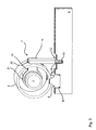
- the FIG. 1 shows in the schematic, three-dimensional representation of a section of a switching device 1 with a locking system.
- the switching device 1 comprises a switching shaft 2, which is technically coupled at its free end with a user operable by a driver manual shift lever.
- the switching shaft 2 is displaceable along the arrow 3 in its axial extent and also arranged in the direction of rotation according to arrow 4 about its own axis pivotally.
- the switching device 1 comprises a switching sleeve 5, which is arranged coaxially with the switching shaft 2 and with this displacement and pivoting, for example, materially bonded, in particular by welding, is connected.
- the shift sleeve 5 carries on its outer side a cam crest 6, which receives a spring-loaded latching cam 7, and one or more shift finger 8, which extends in the radial direction of the shift sleeve 5 and is connected cohesively thereto.
- the switching device For the transmission of switching movements to a manual transmission, not shown, the switching device 1, three shift rails 9, which are aligned parallel to each other and perpendicular to the shift shaft 2. At their switching shaft 2 facing end portions, the shift rails 9 each have a switching mouth 10, which is formed as a rectangular, edge-open recess.
- the shift shaft 2 is displaced along the arrow 3, so that the shift finger 8 is positioned in the shift jaw 10 of a desired shift rail 9.
- the shift finger 8 is pivoted about the shift shaft 2, pushes the selected shift rail 9 in dependence of the pivoting direction in FIG. 2 to the left or to the right, thus entering a desired gear.
- the switching device 1 has a locking device 11.
- the locking device 11 which is designed for example as a stamped and bent part, comprises a locking portion 12, which is formed as a first, planar sheet metal section and engages in the shift rails 9 arranged in offset to the Wegaugru 10 Verriegelungsmäuler 13, wherein this perpendicular to the longitudinal extent of the shift rails 9 can be moved by the switching shaft 2.
- the locking portion 12 has a recess 14 which is adapted in width in the direction of extension of the arrow 3 to the widths of one of the shift rails 9 such that depending on the position of the locking portion 12, one of the shift rails 9 is switchable, whereas the other two shift rails 9 locked are.
- the middle shift rail 9 is switchable, that is, displaceable in its longitudinal extent and the other two shift rails 9 locked by the locking portion 12.
- the locking device 11 has a guide section 15, which is formed as a second, planar sheet metal section, in which a guide groove 16 and a guide channel 16 is introduced.
- a guide pin 17 which is rigidly and / or fixedly connected to the housing 18 or - in other embodiments - with the gear dome housing.
- Guide channel 16 and guide pin 17 define a positive guide for the second sheet metal section and thus for the locking portion 12, so that Although this displaced in the direction of arrow 3, but not in the circumferential direction of the switching shaft 2 according to arrow 4 is pivotable.
- the guide plate 16 carrying the second sheet metal portion and the locking portion 12 supporting the first sheet metal portion form a common, planar and / or unbent and / or undeformed sheet metal section in its surface extension a locking plane, ie a plane in which the locking portion is and is moved, and at the same time defines a coplanar and / or congruent shift plane, ie a sliding plane in which the guide section 15 is located and displaced.
- this two driving leg 19 which extend at right angles from the common sheet metal section formed by the first and second sheet metal section.
- the driving leg 19 engage by two introduced in the shift sleeve 5, extending in the circumferential direction, channel-shaped guide grooves 20 and have at their free end in each case a disc-annular end portion 21, through the free passage opening the shift shaft 2 is freely rotatably threaded.
- the locking device is entrained in an axial displacement of the switching shaft 2 according to arrow 3 on the shift sleeve 5, wherein the driving leg 19 abut against the boundaries of the guide grooves 20 positively and force-transmitting.
- the guide grooves 20 extend so far that the composite formed from shift shaft 2 and shift sleeve 5 is pivotable for a switching movement without taking the locking device 11, so that the locking device 11 is decoupled from the pivotal movement of the shift shaft 2 is arranged ,
- the FIG. 4 shows a second embodiment of a switching device 1 in a cut, three-dimensional representation.
- the switching device 1 has a in the FIG. 4 centrally extending shift shaft 2, which a first shift finger 8 a and axially spaced therefrom a second shift finger 8 b carries.
- the shift fingers 8a and 8b are arranged and configured to intervene in perpendicular to the shift shaft 2 arranged shift rails 9 a, b, c, d.
- the shift rails 9 a, b, c, d each have a shift jaw 10.
- FIG. 4 shows a second embodiment of a switching device 1 in a cut, three-dimensional representation.
- the switching device 1 has a in the FIG. 4 centrally extending shift shaft 2, which a first shift finger 8 a and axially spaced therefrom a second shift finger 8 b carries.
- the shift fingers 8a and 8b are arranged and configured to intervene in perpendicular to the shift shaft 2 arranged shift rails 9
- the shift shaft 2 occupy four preselection positions, so that in a first preset position, the shift rail 9 a, in a second preset position the shift rail 9 b, in a third preset position the shift rail 9 c and in a fourth dial position the shift rail 9 d is selected.
- the switching device 1 For additional guidance of the switching shaft 2, the switching device 1, a shift gate 22, into which engages a link finger 23 depending on the selected position.
- the locking system 1 shows a cam crest 6, in which a locking cam 7 engages.
- a locking device 11 is in the FIG. 4 essentially formed as a planar sheet metal section, which in the region of the two shift rail groups 9 a, c and 9 b, d respectively carries a locking portion 12, wherein each locking portion 12 has a recess 14 which by displacement of the locking device 11 in the axial direction according to arrow 3 in a release position for a selected shift rail 9 a, b, c, d, can be brought.
- a guide portion 15 of the locking device 11 is a portion of the flat sheet metal portion and has two guide pins 24 which are fixed in the guide portion 15 and guided in guide channels 16 which are inserted in a housing-fixed guide plate 25.
- Guide plate 25 and guide channels 16 thus form a housing-side guide member.
- the engagement is realized so that when an axial displacement of the switching shaft 2, the locking device 11 by the shift finger 8 a, b, is guided, whereas at a pivoting of the switching shaft 2 in the direction of rotation according to arrow 4, the gap in the fork of the shift finger 8 a, b, is designed so that the shift finger 8 a, b, can freely pivot without entrainment of the locking device 11.
- the locking element 11 shows in FIG. 4 as an easy-to-manufacture component, which can be produced cost-effectively by a punching process with a subsequent insertion of the guide pins 24.
Abstract
Description
Die Erfindung betrifft eine Schaltvorrichtung für ein Schaltgetriebe eines Kraftfahrzeugs mit einer Verriegelungseinrichtung, mit einer Schaltwelle zur Vorwahl und zum Schalten von Gängen in dem Schaltgetriebe, mit einer Mehrzahl von Schaltschienen zur Übertragung der Schaltmomenten von der Schaltwelle zu dem Schaltgetriebe, wobei die Schaltwelle senkrecht zu den Schaltschienen ausgerichtet ist und zur Vorwahl von Gängen axial verschiebbar und zum Schalten von Gängen um die eigene Achse schwenkbar angeordnet ist, wobei die Verriegelungseinrichtung einen Verriegelungsabschnitt zur Freigabe einer der Schaltschienen und zur Verriegelung der anderen Schaltschienen und einen Führungsabschnitt zur axialen Führung der Verriegelungseinrichtung an einem gehäusefesten Führungsorgan aufweist, wobei die Verriegelungseinrichtung ausgebildet und/oder angeordnet ist, so dass diese bei einer axialen Verschiebung der Schaltwelle zur Vorauswahl der Gänge mitgeführt und bei einer Verschwenkung der Schaltachse zum Schalten der Gänge freiläuft.The invention relates to a switching device for a manual transmission of a motor vehicle with a locking device, with a selector shaft for preselection and for shifting gears in the transmission, with a plurality of shift rails for transmitting the switching torque from the shift shaft to the transmission, wherein the shift shaft perpendicular to the Gear shift rails is aligned and for the selection of gears axially displaceable and pivotally arranged for shifting gears about its own axis, wherein the locking device comprises a locking portion for releasing one of the shift rails and for locking the other shift rails and a guide portion for axially guiding the locking device to a housing Having guide member, wherein the locking device is formed and / or arranged so that they entrained in an axial displacement of the shift shaft for preselection of the gears and at a pivoting the shift axle freewheeling for shifting the gears.
In vielen Fahrzeugen werden Schalt- und Wählbewegungen, die von einem Fahrer über einen Handschalthebel eingeleitet werden, über eine Schaltwelle übertragen, die auf eine Mehrzahl von Schaltschienen wirkt, die dann letztlich das Schaltmoment von der Schaltwelle zu einem Schaltgetriebe übertragen. Zur Auswahl einer bestimmten Schaltschiene wird die Schaltwelle bei bekannten Bauformen axial verschoben, zum Einlegen oder Schalten eines gewählten Ganges wird durch eine Schwenkbewegung der Schaltwelle um die eigene Achse die gewählte Schaltschiene in ihrer Längserstreckung verschoben.In many vehicles switching and Wählbewegungen which are initiated by a driver via a manual shift lever, transmitted via a switching shaft which acts on a plurality of shift rails, which then ultimately transmit the switching torque from the shift shaft to a manual transmission. To select a specific shift rail, the shift shaft is axially displaced in known designs, for inserting or switching a selected Ganges is moved by a pivoting movement of the shift shaft about its own axis, the selected shift rail in its longitudinal extent.
Problematisch insbesondere bei einem manuellen Schalten von Gängen ist es, wenn fälschlicherweise nicht einer der beiden Gänge der gewünschten Schaltschiene eingelegt, sondern "diagonal geschaltet" wird, so dass ein Gang einer der anderen Schaltschienen geschaltet wird. Ein derartiges "Verschalten" führt zu dem Einlegen eines falschen Ganges, so dass im ungünstigstem Fall die Drehzahl und die Drehrichtung von Getriebe und Antriebsmotor nicht übereinstimmen und unerwartete Fahrsituationen oder sogar Beschädigungen des Schaltgetriebes bzw. des Antriebsmotors auftreten können.A problem in particular with a manual shift of gears is when incorrectly not one of the two gears of the desired shift rail is inserted, but "switched diagonally", so that a gear of one of the other shift rails is switched. Such a "connection" leads to the insertion of a wrong gear, so that in the worst case the speed and direction of rotation of the gearbox and drive motor do not match and unexpected driving situations or even damage to the gearbox or the drive motor can occur.
Um ein derartiges "Verschalten" auszuschließen, sind Verriegelungssysteme bekannt, welche zwischen Schaltwelle und Schaltgetriebe angeordnet und ausgebildet sind, dass die nicht-gewählten Schaltschienen verriegelt und nur die gewählte Schaltschiene für einen Schaltvorgang freigegeben ist. Das Verriegelungssystem stellt somit sicher, dass der Fahrer durch eine Schaltbewegung nur einen Gang in der gewählten Schaltgasse bzw. der gewählten Schaltschiene einlegen kann.In order to exclude such a "interconnection", locking systems are known, which are arranged and formed between the shift shaft and gearbox that locks the non-selected shift rails and only the selected shift rail is released for a switching operation. The locking system thus ensures that the driver can insert only one gear in the selected shift gate or the selected shift rail by a switching movement.
Ein derartiges Verriegelungssystem ist beispielsweise aus der Druckschrift
Die Druckschrift
Die gattungsgemäße
Der Erfindung liegt die Aufgabe zugrunde, eine Schaltvorrichtung mit Verriegelungseinrichtung zur Verriegelung von Schaltschienen für ein Schaltgetriebe von Kraftfahrzeugen vorzuschlagen, welche betriebssicher und kostengünstig ist.The invention has for its object to provide a switching device with locking device for locking shift rails for a manual transmission of motor vehicles, which is reliable and inexpensive.
Diese Aufgabe wird durch ein Verriegelungssystem mit Merkmalen des Anspruchs 1 gelöst. Bevorzugte oder vorteilhafte Ausführungsformen der Erfindung ergeben sich aus den Unteransprüchen, der nachfolgenden Beschreibung und/oder den beigefügten Figuren.This object is achieved by a locking system with features of claim 1. Preferred or advantageous embodiments of the invention will become apparent from the dependent claims, the following description and / or the accompanying figures.
Erfindungsgemäß wird eine Schaltvorrichtung mit Verriegelungseinrichtung zur Verriegelung von Schaltschienen für ein Schaltgetriebe von Kraftfahrzeugen vorgeschlagen, wobei das Schaltgetriebe vorzugsweise als ein mechanisches, mehrgängiges Zahnräderwechselgetriebe ausgebildet ist.According to the invention, a switching device with locking device for locking shift rails for a manual transmission of motor vehicles is proposed, wherein the transmission is preferably designed as a mechanical, multi-speed change-speed gearbox.
Als Bestandteile zählen zu der Schaltvorrichtung eine Schaltwelle, welche vorzugsweise über einen Handschalthebel betätigbar ist und welche zur Vorwahl und zum Schalten von Gängen in dem Schaltgetriebe angeordnet und/oder ausgebildet ist. Zur Übertragung der Schaltmomente von der Schaltwelle zu dem Schaltgetriebe ist eine Mehrzahl von Schaltschienen, vorzugsweise drei Schaltschienen zur Schaltung von sechs Gängen vorgesehen. Bei alternativen Ausführungsformen kann auch eine entsprechende Anzahl von Schaltschienen zur Schaltung einer anderen Gangzahl verwirklicht sein. Konstruktiv betrachtet ist die Schaltwelle - insbesondere in einer Draufsicht in radialer Richtung auf die Schaltwelle - senkrecht oder im Wesentlichen senkrecht zu den Schaltschienen ausgerichtet. Die Schaltwelle ist zur Vorwahl von Gängen bzw. Schaltschienen entlang ihrer eigenen Achse axial verschiebbar und zum Schalten von Gängen um die eigene Achse schwenkbar angeordnet. Beispielsweise weist die Schaltwelle einen Schaltfinger auf, welcher durch eine axiale Verschiebung der Schaltwelle zwischen den Schaltschienen verschoben werden kann und durch eine Schwenkung der Schaltwelle um die eigene Achse eine gewählte Schaltschiene in deren Längserstreckung verschiebt, um den entsprechenden Gang einzulegen.As components of the switching device include a switching shaft, which is preferably actuated via a manual shift lever and which for preselection and arranged and / or formed for shifting gears in the manual transmission. To transmit the switching moments of the shift shaft to the transmission, a plurality of shift rails, preferably three shift rails for switching six gears is provided. In alternative embodiments, a corresponding number of shift rails for shifting a different number of gears can be realized. Structurally considered, the shift shaft - in particular in a plan view in the radial direction of the shift shaft - aligned perpendicular or substantially perpendicular to the shift rails. The switching shaft is axially displaceable for the selection of gears or shift rails along its own axis and pivotally arranged for shifting gears about its own axis. For example, the shift shaft on a shift finger, which can be moved by an axial displacement of the shift shaft between the shift rails and shifts a selected shift rail in its longitudinal extent by pivoting the shift shaft about its own axis to engage the appropriate gear.
Das Verriegelungssystem weist eine ein- oder mehrteilige Verriegelungseinrichtung auf, welche mindestens zwei funktionale Bereiche zeigt: Ein funktionaler Bereich betrifft einen Verriegelungsabschnitt, welcher in einer gewählten Position eine der Schaltschienen freigibt und die anderen Schaltschienen zugleich verriegelt. Durch Änderung der Vorwahl wird zugleich die freigegebene Schaltschiene geändert. Ein weiterer funktionaler Bereich betrifft einen Führungsabschnitt, welcher zur axialen Führung, insbesondere in axialer Erstreckung der Schaltwelle, der Verriegelungseinrichtung zusammen mit einem gehäusefesten Führungsorgan ausgebildet ist. Insbesondere ist das Führungsorgan an einem Schaltdomgehäuse, welcher die Schaltwelle und die Schaltschienen zumindest abschnittsweise aufnimmt, und/oder einem Getriebegehäuse starr und/oder ortsfest angeordnet. Die axiale Führung ist vorzugsweise so ausgebildet, dass die Verriegelungseinrichtung verdrehsicher in Umfangsrichtung um die Schaltwelle geführt ist.The locking system comprises a one- or multi-part locking device, which shows at least two functional areas: A functional area relates to a locking portion which releases one of the shift rails in a selected position and locks the other shift rails at the same time. Changing the preselection also changes the released shift rail. Another functional area relates to a guide portion, which is designed for axial guidance, in particular in the axial extent of the switching shaft, the locking device together with a housing-fixed guide member. In particular, the guide member to a Schaltdomgehäuse which receives the shift shaft and the shift rails, at least in sections, and / or a transmission housing rigidly and / or stationary. The axial guide is preferably formed so that the locking device is guided against rotation in the circumferential direction about the shift shaft.
Die Verriegelungseinrichtung ist derart ausgebildet und/oder angeordnet, so dass diese bei einer axialen Verschiebung der Schaltwelle zur Vorauswahl der Gänge mitgeführt wird, um - wie bereits erläutert - eine der Schaltschienen freizugeben und die anderen zu verriegeln, und bei einer Verschwenkung der Schaltachse zum Einlegen der Gänge jedoch freiläuft und von der Schwenkbewegung der Schaltwelle mechanisch entkoppelt ist.The locking device is designed and / or arranged so that it is carried on an axial displacement of the shift shaft for preselection of the gears to - as already explained - release one of the shift rails and lock the other, and at a pivoting of the shift axis for insertion the gears, however, freewheeled and mechanically decoupled from the pivotal movement of the shift shaft.
Der Verriegelungsabschnitt ist als ein erster ebener Blechabschnitt ausgebildet, der in Flächenerstreckung eine Verriegelungsebene definiert. Zwischen Führungsabschnitt und dem Führungsorgan befindet sich eine flächige Gleit- und/oder Verschiebeebene, welche als Führungsebene definiert wird. Erfindungsgemäß wird vorgeschlagen, dass die Verriegelungsebene und die Führungsebene auf der gleichen Seite der Schaltwelle, also so, dass die eigene Achse der Schaltwelle nicht zwischen den Ebenen angeordnet ist, zueinander parallel angeordnet sind.The locking portion is formed as a first planar sheet metal portion defining a locking plane in surface extension. Between guide portion and the guide member is a flat sliding and / or displacement plane, which is defined as a management level. According to the invention it is proposed that the locking plane and the guide plane on the same side of the switching shaft, so that the own axis of the switching shaft is not arranged between the planes are arranged parallel to each other.
Vorzugsweise sind Verriegelungsabschnitt und Führungsabschnitt in axialer Richtung der Schaltwelle versetzt zueinander angeordnet und/oder in axialer Draufsicht zueinander parallel und/oder deckungsgleich und/oder überlappend positioniert. Bei einer besonders bevorzugten Ausführungsform der Erfindung sind die Verriegelungsebene und die Führungsebene zueinander koplanar angeordnet, wobei die beiden Ebenen zusammenfallen.Locking section and guide section are preferably arranged offset to one another in the axial direction of the switching shaft and / or positioned parallel and / or congruent with one another in axial plan view and / or overlapping. In a particularly preferred embodiment of the invention, the locking plane and the guide plane are arranged coplanar to each other, wherein the two planes coincide.
Eine Überlegung der Erfindung ist es, dass die aus dem Stand der Technik bekannten Verriegelungssysteme mit Sperrblechen mechanisch kompliziert aufgebaut und insbesondere bei der Fertigung und Montage aufwendig sind. Dies liegt nicht zuletzt daran, dass die Verriegelungsbereiche und die Führungsbereiche der bekannten Sperrbleche relativ zu der Schaltwelle gegenüberliegend oder in einem 90 °-Winkel zueinander angeordnet sind. Diese Anordnung führt dazu, dass die Sperrbleche als komplexe 3-D-Gebilde realisiert sein müssen, deren toleranzarme Fertigung und Montage mit einem hohen Aufwand verbunden ist. Demgegenüber schlägt die Erfindung vor, den Verriegelungsabschnitt und den Führungsabschnitt auf einer gemeinsamen Seite der Schaltwelle anzuordnen, was zu einer fertigungstechnischen Vereinfachung führt. Bei einer besonders bevorzugten konstruktiven Ausführung der Erfindung weist der Führungsabschnitt des Führungselements einen zweiten ebenen Blechabschnitt auf, dessen Flächenerstreckung die Gleitebene definiert. Somit werden Verriegelungsabschnitt und Führungsabschnitt jeweils durch einen ebenen Blechabschnitt mitgestaltet, wobei die durch die Blechabschnitte definierten Ebenen zueinander parallel und/oder koplanar angeordnet sind.A consideration of the invention is that the known from the prior art locking systems constructed with locking plates mechanically complicated and are particularly expensive to manufacture and assembly. This is not least because the locking areas and the guide areas of the known locking plates are arranged relative to the switching shaft opposite or at a 90 ° angle to each other. This arrangement means that the locking plates must be realized as a complex 3-D structure whose low-tolerance manufacturing and assembly is associated with a lot of effort. In contrast, the invention proposes the locking portion and the guide portion on a common side of the To arrange switching shaft, resulting in a manufacturing simplification. In a particularly preferred constructional embodiment of the invention, the guide section of the guide element has a second flat sheet metal section whose surface extension defines the sliding plane. Thus, locking portion and guide portion are each mitgestaltet by a flat sheet metal portion, wherein the planes defined by the sheet metal sections are arranged parallel to each other and / or coplanar.
Bei einer besonders bevorzugten Weiterbildung der Erfindung bilden erster und zweiter ebener Blechabschnitt einen gemeinsamen, ebenen Blechabschnitt. Bei dieser Weiterbildung der Erfindung ist die Fertigung der Verriegelungseinrichtung besonders einfach, da Verriegelungsabschnitt und Führungsabschnitt durch einen einfachen Trennvorgang, zum Beispiel, durch eine Stanzung, herstellbar sind. Insbesondere sind in dem Bereich der genannten zwei Abschnitten keine Umformschritte notwendig. Damit ist die Verriegelungseinrichtung im Bereich der genannten zwei Abschnitte kostengünstig und mit hoher Genauigkeit fertigbar.In a particularly preferred embodiment of the invention, first and second planar sheet metal sections form a common, flat sheet metal section. In this embodiment of the invention, the production of the locking device is particularly simple, since the locking section and guide section by a simple separation process, for example, by a punched, can be produced. In particular, no forming steps are necessary in the area of said two sections. Thus, the locking device in the region of said two sections is inexpensive and manufacturable with high accuracy.
Bei einer möglichen, konstruktiven Umsetzung weist der Verriegelungsabschnitt eine randseitig offene Aussparung auf, die beispielsweise in Form eines Rechtecks gebildet ist, deren Breite an die Breite einer der Schaltschienen derart angepasst ist, dass jeweils die anderen Schaltschienen gesperrt sind. Die Aussparung bildet somit einen Durchlassbereich für genau eine Schaltschiene.In a possible, constructive implementation of the locking portion has a recess open at the edge, which is formed for example in the form of a rectangle whose width is adapted to the width of one of the shift rails such that in each case the other shift rails are locked. The recess thus forms a passage area for exactly one shift rail.
Bei einer Weiterbildung dieser Ausführungsform weisen die Schaltschienen Verriegelungsmäuler auf, in die der Verriegelungsabschnitt eingreift. Auch die Verriegelungsmäuler weisen in seitlicher Draufsicht einen vorzugsweise rechteckigen Querschnitt auf.In a further development of this embodiment, the shift rails on locking mouths, in which engages the locking portion. The locking mouths also have a preferably rectangular cross-section in a lateral plan view.
Bei einer weiteren bevorzugten Ausbildung der Erfindung umfassen entweder der Führungsabschnitt oder das Führungsorgan einen axial, insbesondere in axialer Erstreckung der Schaltwelle, ausgerichteten Führungskanal, wohingegen der jeweilige Partner, also das Führungsorgan bzw. der Führungsabschnitt, ein Führungselement, insbesondere einen Führungsstift aufweist, welches durch den Führungskanal in axialer Richtung geführt ist. Bei einer besonders bevorzugten Ausführungsform der Erfindung ist die Längserstreckung des Führungselements so angeordnet, dass diese in axialer Draufsicht auf die Schaltwelle senkrecht zu der Schaltwelle angeordnet ist, diese jedoch nicht schneidet.In a further preferred embodiment of the invention, either the guide portion or the guide member comprise an axially, in particular in the axial extent of the switching shaft, aligned guide channel, whereas the respective partner, so the guide member or the guide portion, a guide element, in particular a guide pin which is guided by the guide channel in the axial direction. In a particularly preferred embodiment of the invention, the longitudinal extent of the guide element is arranged so that it is arranged in an axial plan view of the switching shaft perpendicular to the shift shaft, but this does not intersect.
Zur mechanischen Kopplung die Verriegelungseinrichtung und der Schaltwelle weist die Verriegelungseinrichtung einen Mitnahmeabschnitt und die Schaltwelle ein Mitnahmeorgan auf, welche derart ausgestaltet sind, dass die Verriegelungseinrichtung von der Schaltwelle bei einer axialen Bewegung der Schaltwelle mitgenommen, bei einer Schwenkbewegung der Schaltwelle, zumindest im Rahmen der Vorwahlschwenkung, ungekoppelt ist bzw. frei läuft. Diese Funktionalität erlaubt es, dass die Verriegelungseinrichtung bei einer Vorwahl von einer Schaltschiene zur nächsten Schaltschiene verschoben wird, bei einer Schaltbewegung der Schaltwelle dagegen nicht bewegt wird.For mechanical coupling, the locking device and the switching shaft, the locking device has a driving portion and the switching shaft on a driving member, which are designed such that the locking device of the shift shaft in an axial movement of the shift shaft taken at a pivotal movement of the shift shaft, at least in the context of pre-selection , is uncoupled or runs free. This functionality allows the locking device is moved in a preselection of a shift rail to the next shift rail, it is not moved in a switching movement of the shift shaft, however.
Bei einer ersten möglichen Ausführungsform der Erfindung ist das Mitnahmeorgan als ein Schaltfinger ausgebildet, welcher in einer randseitig offenen Aussparung des Mitnahmeabschnitts der Verriegelungseinrichtung eingreift. Bei dieser Ausführungsform wird die Verriegelungseinrichtung durch den Schaltfinger verschoben. Bei einer bevorzugten Realisierung dieser Ausführungsform weist der Schaltfinger endseitig eine Gabel auf, deren freier Gabelraum in Umfangsrichtung der Schaltwelle so dimensioniert ist, dass die Schaltwelle in azimutaler Richtung gegenüber der Verriegelungseinrichtung im Rahmen der Vorwahlschwenkung frei schwenken kann.In a first possible embodiment of the invention, the entrainment member is designed as a shift finger, which engages in an edge-open recess of the driving portion of the locking device. In this embodiment, the locking device is displaced by the shift finger. In a preferred realization of this embodiment, the shift finger has a fork at its end whose free fork space is dimensioned in the circumferential direction of the shift shaft such that the shift shaft can pivot freely in the azimuthal direction relative to the locking device in the context of the pre-selection pivoting.
Bei einer zweiten Ausführungsform der Erfindung ist das Mitnahmeorgan als eine Schalthülse ausgebildet, auf der vorzugsweise mindestens ein Schaltfinger und/oder ein Nockenkamm angeordnet ist bzw. sind. Bei der zweiten Ausführungsform ist der Mitnahmeabschnitt als mindestens ein Mitnahmeschenkel ausgebildet, der sich in radialer Richtung zu der Schaltwelle erstreckt. Vorzugsweise ist der Mitnahmeschenkel auf der Schaltwelle, zum Beispiel über eine Durchgangsöffnung in dem Mitnahmeschenkel, schwenkbar aufgefädelt.In a second embodiment of the invention, the driving member is formed as a switching sleeve on which preferably at least one shift finger and / or a cam comb is or are arranged. In the second embodiment, the driving portion is formed as at least one driving leg, which extends in the radial direction to the switching shaft. Preferably is the driving leg on the switching shaft, for example, via a passage opening in the driving leg, hinged threaded.
Bei dieser Ausführungsform ist vorzugsweise vorgesehen, dass in die Schalthülse eine in Umlaufrichtung verlaufende Mitnahmenut zur Durchführung und axialen Mitnahme des Mitnahmeschenkels eingebracht ist. Vorzugsweise, insbesondere zur Stabilisierung der Verriegelungseinrichtung, weist diese zwei Mitnahmeschenkel auf, welche von zwei in Umlaufrichtung verlaufenden Mitnahmenuten in der Schalthülse mitgeführt bzw. freigegeben sind.In this embodiment, it is preferably provided that in the shift sleeve extending in the circumferential direction driving groove for carrying and axial entrainment of the driving leg is introduced. Preferably, in particular for stabilizing the locking device, has these two driving leg, which are carried or released by two extending in the direction of rotation driving grooves in the shift sleeve.
Bei einer produktnahen Realisierung der Erfindung ist der bzw. die Mitnahmeschenkel rechtwinklig zum ersten, zweiten und/oder oder dritten Blechabschnitt angeordnet. Bei dieser Ausführungsform ist die Verriegelungseinrichtung in einer Längsschnittansicht durch die Schaltwelle vorzugsweise L- bzw. U-förmig ausgebildet, so dass das Verriegelungselement in dieser oder anderer Realisierung in kostengünstiger Weise durch eine Stanz-Biege-Verfahrensfolge herstellbar ist.In a product-related implementation of the invention, the or the driving leg is arranged at right angles to the first, second and / or third sheet metal section. In this embodiment, the locking device in a longitudinal sectional view through the switching shaft preferably L- or U-shaped, so that the locking element in this or other realization in a cost effective manner by a punching-bending process sequence can be produced.
Weitere Merkmale, Vorteile und Wirkungen der Erfindung ergeben sich aus der nachfolgenden Beschreibung bevorzugter Ausführungsbeispiele und Zeichnungen der Erfindung. Dabei zeigen:
- Figur 1
- eine Schaltvorrichtung mit einer Verriegelungseinrichtung als ein erstes Ausführungsbeispiel der Erfindung in einer schematischen, dreidimensionalen Darstellung schräg von der Seite;
Figur 2- die Verriegelungseinrichtung in
Figur 1 in einer schematischen, dreidimensionalen Darstellung schräg von vorne; - Figur 3
- die Verriegelungseinrichtung in den
Figuren 1 und2 in einer drei- dimensionalen, schematischen Schnittdarstellung in einer Radial- ebene senkrecht zu der Schaltwelle; Figur 4- eine Schaltvorrichtung mit einer Verriegelungseinrichtung als ein zweites Ausführungsbeispiel der Erfindung in einer schemati- schen, dreidimensionalen Längsschnittdarstellung in einer Ebene durch die Schaltwelle.
- FIG. 1
- a switching device with a locking device as a first embodiment of the invention in a schematic, three-dimensional representation obliquely from the side;
- FIG. 2
- the locking device in
FIG. 1 in a schematic, three-dimensional representation obliquely from the front; - FIG. 3
- the locking device in the
FIGS. 1 and2 in a three-dimensional, schematic sectional view in a radial plane perpendicular to the shift shaft; - FIG. 4
- a switching device with a locking device as a second embodiment of the invention in a schematic, three-dimensional longitudinal sectional view in a plane through the switching shaft.
Gleiche oder einander entsprechende Teile sind in den Figuren jeweils mit den gleichen oder entsprechenden Bezugszeichen versehen.The same or corresponding parts are each provided with the same or corresponding reference numerals in the figures.
Die
Zur Übertragung von Schaltbewegungen an ein nicht dargestelltes Schaltgetriebe weist die Schaltvorrichtung 1 drei Schaltschienen 9 auf, welche zueinander parallel und senkrecht zu der Schaltwelle 2 ausgerichtet sind. An ihren der Schaltwelle 2 zugewandten Endabschnitten weisen die Schaltschienen 9 jeweils ein Schaltmaul 10 auf, welches als rechteckige, randseitig geöffnete Aussparung ausgebildet ist.For the transmission of switching movements to a manual transmission, not shown, the switching device 1, three
Zur Durchführung einer Wählbewegung wird die Schaltwelle 2 entlang des Pfeils 3 verschoben, so dass der Schaltfinger 8 in dem Schaltmaul 10 einer gewünschten Schaltschiene 9 positioniert wird. Durch eine Schwenkung der Schaltwelle entlang des Pfeils 4 wird der Schaltfinger 8 um die Schaltwelle 2 verschwenkt, schiebt die gewählte Schaltschiene 9 in Abhängigkeit der Schwenkrichtung in
Um nun zu vermeiden, dass durch eine ungeschickte Bewegung des Fahrers der Schaltfinger 8 so geführt wird, dass nicht eine gewählte Schaltschiene 9, sondern eine benachbarte Schaltschiene 9 bewegt wird, weist die Schaltvorrichtung 1 eine Verriegelungseinrichtung 11 auf.In order to avoid that by an awkward movement of the driver of the
Die Verriegelungseinrichtung 11, die beispielsweise als Stanz-Biegeteil ausgebildet ist, umfasst einen Verriegelungsabschnitt 12, welcher als ein erster, ebener Blechabschnitt ausgebildet ist und in versetzt zu den Schaltmäulern 10 angeordnete Verriegelungsmäuler 13 in den Schaltschienen 9 eingreift, wobei dieser senkrecht zur Längserstreckung der Schaltschienen 9 durch die Schaltwelle 2 verschoben werden kann. Der Verriegelungsabschnitt 12 weist eine Aussparung 14 auf, die in der Breite in Erstreckungsrichtung des Pfeils 3 an die Breiten einer der Schaltschienen 9 derart angepasst ist, dass je nach Lage des Verriegelungsabschnitts 12 eine der Schaltschienen 9 schaltbar ist, wohingegen die anderen zwei Schaltschienen 9 verriegelt sind. In der in
Um eine gute Führung des Verriegelungsabschnitts 12 entlang des Pfeils 3 sicherzustellen, weist die Verriegelungseinrichtung 11 einen Führungsabschnitt 15 auf, welcher als ein zweiter, ebener Blechabschnitt ausgebildet ist, in dem eine Führungsnut 16 bzw. ein Führungskanal 16 eingebracht ist. Wie sich wohl am besten aus der
Zur Koppelung der Verriegelungseinrichtung 11 mit der Schaltwelle 2 weist dieses zwei Mitnahmeschenkel 19 auf, welche sich rechtwinklig von dem durch ersten und zweiten Blechabschnitt gebildeten gemeinsamen Blechabschnitt erstrecken. Die Mitnahmeschenkel 19 greifen durch zwei in der Schalthülse 5 eingebrachte, in Umlaufrichtung verlaufende, kanalförmige Führungsnuten 20 und weisen an ihrem freien Ende jeweils einen scheibenringförmigen Endabschnitt 21 auf, durch dessen freie Durchgangsöffnung die Schaltwelle 2 frei drehbar gefädelt ist.For coupling the
Funktionell betrachtet wird die Verriegelungseinrichtung bei einer axialen Verschiebung der Schaltwelle 2 gemäß Pfeil 3 über die Schalthülse 5 mitgenommen, wobei die Mitnahmeschenkel 19 an den Begrenzungen der Führungsnuten 20 formschlüssig und kraftübertragend anliegen. In Umlaufrichtung gemäß Pfeil 4 erstrecken sich die Führungsnuten 20 dagegen so weit, dass der Verbund gebildet aus Schaltwelle 2 und Schalthülse 5 für eine Schaltbewegung verschwenkbar ist, ohne die Verriegelungseinrichtung 11 mitzunehmen, so dass die Verriegelungseinrichtung 11 entkoppelt von der Schwenkbewegung der Schaltwelle 2 angeordnet ist.Functionally considered, the locking device is entrained in an axial displacement of the switching
Die
Eine Verriegelungseinrichtung 11 ist in der
Ein Führungsabschnitt 15 der Verriegelungseinrichtung 11 ist ein Abschnitt des ebenen Blechabschnitts und weist zwei Führungsstifte 24 auf, die in dem Führungsabschnitt 15 festgelegt sind und in Führungskanälen 16, welche in einem gehäusefesten Führungsblech 25 eingebracht sind, geführt werden. Führungsblech 25 und Führungskanäle 16 bilden damit ein gehäuseseitiges Führungsorgan.A
Zur Verstellung der axialen Position gemäß Pfeil 3 der Verriegelungseinrichtung 11 weist diese Führungsaussparungen 26 auf, in die als Gabeln ausgebildete Endabschnitte der Schaltfinger 8 a bzw. 8 b eingreifen. Der Eingriff ist dabei so realisiert, dass bei einer axialen Verschiebung der Schaltwelle 2 die Verriegelungseinrichtung 11 durch die Schaltfinger 8 a, b, geführt wird, wohingegen bei einer Verschwenkung der Schaltwelle 2 in Umlaufrichtung gemäß Pfeil 4 der Zwischenraum in der Gabel der Schaltfinger 8 a, b, so ausgebildet ist, dass der Schaltfinger 8 a, b, ohne Mitnahme der Verriegelungseinrichtung 11 frei schwenken kann.For adjusting the axial position according to arrow 3 of the
Auch bei der zweiten Ausführungsform gemäß
- 11
- Schaltvorrichtungswitching device
- 22
- Schaltwelleshift shaft
- 33
- Pfeil in axialer RichtungArrow in the axial direction
- 44
- Pfeil in UmlaufrichtungArrow in the direction of rotation
- 55
- Schalthülseswitching sleeve
- 66
- Nockenkammcam crest
- 77
- Rastnockenlocking cams
- 8 a, b8 a, b
- Schaltfingershift finger
- 9, 9 a, b, c, d9, 9 a, b, c, d
- Schaltschieneshift rail
- 1010
- Schaltmaulshift mouthpiece
- 1111
- Verriegelungseinrichtunglocking device
- 1212
- Verriegelungsabschnittlocking section
- 1313
- Verriegelungsmaullock jaw
- 1414
- Aussparungrecess
- 1515
- Führungsabschnittguide section
- 1616
- Führungsnut in axialer RichtungGuide groove in the axial direction
- 1717
-
Führungsstift im Eingriff mit der Führungsnut 16Guide pin in engagement with the
guide groove 16 - 1818
- Gehäusecasing
- 1919
- Mitnahmeschenkelentrainment leg
- 2020
- Führungsnut in UmlaufrichtungGuide groove in the direction of rotation
- 2121
- Endabschnittend
- 2222
- Schaltkulisseshift gate
- 2323
- Kulissenfingersliding finger
- 2424
-
Führungsstift im Eingriff mit der Führungsnut 20Guide pin in engagement with the
guide groove 20 - 2525
- Führungsblechguide plate
- 2626
- Führungsaussparungguide recess
Claims (15)
- Shift device (1) for a shift gearbox of a motor vehicle having a locking device (11), having a shift shaft (2) for preselecting and for shifting gears in the shift gearbox, having a multiplicity of shift rails (9) for transmitting the shift torques from the shift shaft (2) to the shift gearbox,
the shift shaft (2) being aligned perpendicular to the shift rails (9) and being arranged so as to be axially movable for the preselection of gears and pivotable about its own axis for the shifting of gears,
the locking device (11) having a locking section (12) for releasing one of the shift rails (9) and for locking the other shift rails and having a guide section (15) for the axial guidance of the locking device (11) on a guide member fixed with respect to a housing,
the locking device (11) being designed and/or arranged so as to be carried along in the event of an axial movement of the shift shaft (2) for the preselection of the gears and so as to freewheel in the event of a pivoting movement of the shift shaft for the shifting of the gears,
characterized
in that the locking section (12) is designed as a first planar sheet-metal section which, in areal extent, defines a locking plane, and in that a guide plane is defined, as a movement plane, between the guide section (15) and the guide member, the locking plane and the guide plane being arranged parallel to one another on the same side of the shift shaft (2), that is to say such that the own axis of the shift shaft (2) is not arranged between the planes. - Shift device (1) according to Claim 1, characterized in that the locking plane and the guide plane are arranged in a coplanar configuration with respect to one another.
- Shift device (1) according to Claim 1 or 2, characterized in that the guide section (15) has a second planar sheet-metal section whose areal extent defines the movement plane.
- Shift device (1) according to Claim 3, characterized in that the first and the second planar sheet-metal section form a common planar sheet-metal section.
- Shift device (1) according to one of the preceding claims, characterized in that the locking section (12) has a cutout (14) which is open at the edge and whose width is matched to the width of one of the shift rails (9) such that the other shift rails in each case are locked.
- Shift device (1) according to Claim 5, characterized in that the shift rails have locking jaws (13) into which the locking section (12) engages.
- Shift device (1) according to one of the preceding claims, characterized in that the guide section (15) or the guide member has an axially aligned guide channel (16) and the guide member or the guide section respectively has a guide element, in particular a guide pin (17), which is guided in the axial direction through the guide channel (16).
- Shift device (1) according to one of the preceding claims, characterized in that the locking device (11) has a carry-along section (19, 26) by means of which the locking device (11) is coupled to a carry-along element (5, 8a,b) of the shift shaft (2) so as to be carried along axially and, during the preselection pivoting movement, so as to freewheel azimuthally.
- Shift device (1) according to Claim 8, characterized in that the carry-along element is designed as a shift finger (8 a, b) which engages into a cutout (26) on the edge of the carry-along section of the locking device (11).
- Shift device (1) according to Claim 9, characterized in that the shift finger (8a,b) has on the end side a fork whose free fork space is dimensioned such that the shift shaft (2) can pivot freely in the circumferential direction relative to the locking device (11) during the preselection pivoting movement.
- Shift device (1) according to Claim 8, characterized in that the carry-along element is designed as a shift sleeve (5).
- Shift device (1) according to Claim 11, characterized in that the carry-along section is designed as at least one carry-along limb (19) which extends in the radial direction.
- Shift device (1) according to Claim 12, characterized in that the carry-along limb (19) is threaded onto the shift shaft (2) so as to be pivotable.
- Shift device (1) according to Claim 12 or 13, characterized in that the shift sleeve (5) has a carry-along groove (20), which runs in the circumferential direction, for the leadthrough of, for axially carrying along and/or for azimuthally releasing the carry-along limb (19).
- Shift device (1) according to one of Claims 12 to 14, characterized in that the carry-along limb (19) is arranged at right angles to the first, second and/or third sheet-metal region.
Applications Claiming Priority (2)
| Application Number | Priority Date | Filing Date | Title |
|---|---|---|---|
| DE102007033384 | 2007-07-18 | ||
| PCT/EP2008/057102 WO2009010341A1 (en) | 2007-07-18 | 2008-06-06 | Shifting device for a transmission of a motor vehicle having a locking device |
Publications (2)
| Publication Number | Publication Date |
|---|---|
| EP2179200A1 EP2179200A1 (en) | 2010-04-28 |
| EP2179200B1 true EP2179200B1 (en) | 2011-09-14 |
Family
ID=39761056
Family Applications (1)
| Application Number | Title | Priority Date | Filing Date |
|---|---|---|---|
| EP08760672A Active EP2179200B1 (en) | 2007-07-18 | 2008-06-06 | Shifting device for a transmission of a motor vehicle having a locking device |
Country Status (4)
| Country | Link |
|---|---|
| EP (1) | EP2179200B1 (en) |
| CN (1) | CN101842619B (en) |
| AT (1) | ATE524676T1 (en) |
| WO (1) | WO2009010341A1 (en) |
Cited By (1)
| Publication number | Priority date | Publication date | Assignee | Title |
|---|---|---|---|---|
| DE102014220429A1 (en) | 2014-10-09 | 2016-04-28 | Zf Friedrichshafen Ag | Switching unit for an automated vehicle transmission with a plurality of partial transmissions with locking device |
Families Citing this family (4)
| Publication number | Priority date | Publication date | Assignee | Title |
|---|---|---|---|---|
| DE102008029262B4 (en) * | 2008-06-19 | 2020-03-26 | Schaeffler Technologies AG & Co. KG | Locking device for locking shift rails of a transmission |
| WO2014053135A1 (en) * | 2012-10-01 | 2014-04-10 | Schaeffler Technologies AG & Co. KG | Shifting arrangement for a variable speed transmission of a motor vehicle |
| DE102014209165A1 (en) * | 2014-05-15 | 2015-11-19 | Zf Friedrichshafen Ag | Switching device and motor vehicle |
| CN107631027B (en) * | 2017-11-02 | 2019-06-21 | 苏州东风精冲工程有限公司 | A kind of reverse speed fork offset driving locking structure |
Family Cites Families (7)
| Publication number | Priority date | Publication date | Assignee | Title |
|---|---|---|---|---|
| DE3011131A1 (en) * | 1980-03-22 | 1981-10-01 | Volkswagenwerk Ag, 3180 Wolfsburg | Motor vehicle mechanical gearbox selector mechanism - has restrictor limiting selection movement for particular trains of gears |
| DE3913269A1 (en) | 1989-04-22 | 1990-10-31 | Ford Werke Ag | SWITCHING DEVICE FOR INTERCHANGEABLE GEARBOXES OF MOTOR VEHICLES |
| DE4443523C1 (en) * | 1994-12-07 | 1996-05-02 | Daimler Benz Ag | Switching device for a gear change transmission of a motor vehicle |
| DE19511510C1 (en) * | 1995-03-29 | 1996-07-04 | Daimler Benz Ag | Cam disc arrangement for gear shifting gate |
| TW536597B (en) * | 2001-06-29 | 2003-06-11 | Honda Motor Co Ltd | Changing system in manual transmission |
| FR2852073B1 (en) * | 2003-03-06 | 2005-04-01 | Peugeot Citroen Automobiles Sa | INTERNAL CONTROL OF PILOTED GEARBOX |
| JP4235502B2 (en) * | 2003-07-09 | 2009-03-11 | 本田技研工業株式会社 | Shift change device for manual transmission |
-
2008
- 2008-06-06 EP EP08760672A patent/EP2179200B1/en active Active
- 2008-06-06 WO PCT/EP2008/057102 patent/WO2009010341A1/en active Application Filing
- 2008-06-06 CN CN200880025135.6A patent/CN101842619B/en active Active
- 2008-06-06 AT AT08760672T patent/ATE524676T1/en active
Cited By (1)
| Publication number | Priority date | Publication date | Assignee | Title |
|---|---|---|---|---|
| DE102014220429A1 (en) | 2014-10-09 | 2016-04-28 | Zf Friedrichshafen Ag | Switching unit for an automated vehicle transmission with a plurality of partial transmissions with locking device |
Also Published As
| Publication number | Publication date |
|---|---|
| ATE524676T1 (en) | 2011-09-15 |
| WO2009010341A1 (en) | 2009-01-22 |
| CN101842619A (en) | 2010-09-22 |
| CN101842619B (en) | 2013-03-27 |
| EP2179200A1 (en) | 2010-04-28 |
Similar Documents
| Publication | Publication Date | Title |
|---|---|---|
| DE2633730B2 (en) | Mechanical switching device for a gear change transmission | |
| DE10316163A1 (en) | Multi-stage manual transmission for an internal combustion engine | |
| DE19805924A1 (en) | transmission | |
| EP2288826B1 (en) | Method for producing a shift finger arrangement | |
| EP2179200B1 (en) | Shifting device for a transmission of a motor vehicle having a locking device | |
| EP1379797B1 (en) | Single-shaft switching device | |
| DE19901056A1 (en) | Single-shaft vehicle gear selector mechanism with gear-selection lock | |
| DE10203633A1 (en) | Gear shift device | |
| EP2529133B1 (en) | Shift securing device for a multi-speed manual gearbox | |
| DE2653035C3 (en) | Switching device for a motor vehicle change gearbox | |
| DE60014277T2 (en) | Shift fork for transmission of a motor vehicle | |
| DE112005001381B4 (en) | Gearshift system | |
| EP1711727B1 (en) | Gear-shifting device | |
| DE19540522C1 (en) | Gear selector system for vehicle | |
| DE10045266C2 (en) | Switching device for actuating a multi-stage manual transmission | |
| DE102014115371B4 (en) | Switching arrangement for a motor vehicle transmission and switching method | |
| WO2009112343A1 (en) | Actuating apparatus for actuating at least one shift apparatus and method for the assembly and disassembly thereof | |
| DE102006061607A1 (en) | Shifting device for e.g. dual coupling gear of motor vehicle, has shifting rod whose guide bolts are engaged in each guide bar of coupling units, where bolts are attached to gear of common shifting track | |
| EP1680612B1 (en) | Gear-shifting device for a multi-stage manual transmission | |
| DE102014215527A1 (en) | Shift shaft device for a manual transmission and vehicle with the shaft switching device | |
| EP1310707B1 (en) | Shift device for change speed tranmission and method for moving and guiding of shift forks in a transmission | |
| EP1245872B1 (en) | Shift actuator for a change-speed gearbox, particularly for vehicles | |
| DE4441967A1 (en) | Gear change mechanism for multispeed gearbox | |
| EP1440259B1 (en) | Switching device for manual gearshift | |
| DE102006057462A1 (en) | Switch device consists of shift forks on switch member that is adjustable via catches |
Legal Events
| Date | Code | Title | Description |
|---|---|---|---|
| PUAI | Public reference made under article 153(3) epc to a published international application that has entered the european phase |
Free format text: ORIGINAL CODE: 0009012 |
|
| 17P | Request for examination filed |
Effective date: 20100218 |
|
| AK | Designated contracting states |
Kind code of ref document: A1 Designated state(s): AT BE BG CH CY CZ DE DK EE ES FI FR GB GR HR HU IE IS IT LI LT LU LV MC MT NL NO PL PT RO SE SI SK TR |
|
| AX | Request for extension of the european patent |
Extension state: AL BA MK RS |
|
| 17Q | First examination report despatched |
Effective date: 20100802 |
|
| DAX | Request for extension of the european patent (deleted) | ||
| GRAP | Despatch of communication of intention to grant a patent |
Free format text: ORIGINAL CODE: EPIDOSNIGR1 |
|
| GRAS | Grant fee paid |
Free format text: ORIGINAL CODE: EPIDOSNIGR3 |
|
| GRAA | (expected) grant |
Free format text: ORIGINAL CODE: 0009210 |
|
| RAP1 | Party data changed (applicant data changed or rights of an application transferred) |
Owner name: SCHAEFFLER TECHNOLOGIES GMBH & CO. KG |
|
| AK | Designated contracting states |
Kind code of ref document: B1 Designated state(s): AT BE BG CH CY CZ DE DK EE ES FI FR GB GR HR HU IE IS IT LI LT LU LV MC MT NL NO PL PT RO SE SI SK TR |
|
| REG | Reference to a national code |
Ref country code: GB Ref legal event code: FG4D Free format text: NOT ENGLISH |
|
| REG | Reference to a national code |
Ref country code: CH Ref legal event code: EP |
|
| REG | Reference to a national code |
Ref country code: IE Ref legal event code: FG4D Free format text: LANGUAGE OF EP DOCUMENT: GERMAN |
|
| REG | Reference to a national code |
Ref country code: DE Ref legal event code: R096 Ref document number: 502008004883 Country of ref document: DE Effective date: 20111117 |
|
| REG | Reference to a national code |
Ref country code: NL Ref legal event code: VDEP Effective date: 20110914 |
|
| PG25 | Lapsed in a contracting state [announced via postgrant information from national office to epo] |
Ref country code: SE Free format text: LAPSE BECAUSE OF FAILURE TO SUBMIT A TRANSLATION OF THE DESCRIPTION OR TO PAY THE FEE WITHIN THE PRESCRIBED TIME-LIMIT Effective date: 20110914 Ref country code: NO Free format text: LAPSE BECAUSE OF FAILURE TO SUBMIT A TRANSLATION OF THE DESCRIPTION OR TO PAY THE FEE WITHIN THE PRESCRIBED TIME-LIMIT Effective date: 20111214 Ref country code: FI Free format text: LAPSE BECAUSE OF FAILURE TO SUBMIT A TRANSLATION OF THE DESCRIPTION OR TO PAY THE FEE WITHIN THE PRESCRIBED TIME-LIMIT Effective date: 20110914 Ref country code: LT Free format text: LAPSE BECAUSE OF FAILURE TO SUBMIT A TRANSLATION OF THE DESCRIPTION OR TO PAY THE FEE WITHIN THE PRESCRIBED TIME-LIMIT Effective date: 20110914 Ref country code: HR Free format text: LAPSE BECAUSE OF FAILURE TO SUBMIT A TRANSLATION OF THE DESCRIPTION OR TO PAY THE FEE WITHIN THE PRESCRIBED TIME-LIMIT Effective date: 20110914 |
|
| LTIE | Lt: invalidation of european patent or patent extension |
Effective date: 20110914 |
|
| PG25 | Lapsed in a contracting state [announced via postgrant information from national office to epo] |
Ref country code: CY Free format text: LAPSE BECAUSE OF FAILURE TO SUBMIT A TRANSLATION OF THE DESCRIPTION OR TO PAY THE FEE WITHIN THE PRESCRIBED TIME-LIMIT Effective date: 20110914 Ref country code: SI Free format text: LAPSE BECAUSE OF FAILURE TO SUBMIT A TRANSLATION OF THE DESCRIPTION OR TO PAY THE FEE WITHIN THE PRESCRIBED TIME-LIMIT Effective date: 20110914 Ref country code: LV Free format text: LAPSE BECAUSE OF FAILURE TO SUBMIT A TRANSLATION OF THE DESCRIPTION OR TO PAY THE FEE WITHIN THE PRESCRIBED TIME-LIMIT Effective date: 20110914 Ref country code: GR Free format text: LAPSE BECAUSE OF FAILURE TO SUBMIT A TRANSLATION OF THE DESCRIPTION OR TO PAY THE FEE WITHIN THE PRESCRIBED TIME-LIMIT Effective date: 20111215 |
|
| RAP2 | Party data changed (patent owner data changed or rights of a patent transferred) |
Owner name: SCHAEFFLER TECHNOLOGIES AG & CO. KG |
|
| REG | Reference to a national code |
Ref country code: CH Ref legal event code: PFA Owner name: SCHAEFFLER TECHNOLOGIES AG & CO. KG Free format text: SCHAEFFLER TECHNOLOGIES GMBH & CO. KG#INDUSTRIESTRASSE 1-3#91074 HERZOGENAURACH (DE) -TRANSFER TO- SCHAEFFLER TECHNOLOGIES AG & CO. KG#INDUSTRIESTRASSE 1-3#91074 HERZOGENAURACH (DE) |
|
| REG | Reference to a national code |
Ref country code: IE Ref legal event code: FD4D |
|
| PG25 | Lapsed in a contracting state [announced via postgrant information from national office to epo] |
Ref country code: IS Free format text: LAPSE BECAUSE OF FAILURE TO SUBMIT A TRANSLATION OF THE DESCRIPTION OR TO PAY THE FEE WITHIN THE PRESCRIBED TIME-LIMIT Effective date: 20120114 Ref country code: CZ Free format text: LAPSE BECAUSE OF FAILURE TO SUBMIT A TRANSLATION OF THE DESCRIPTION OR TO PAY THE FEE WITHIN THE PRESCRIBED TIME-LIMIT Effective date: 20110914 Ref country code: SK Free format text: LAPSE BECAUSE OF FAILURE TO SUBMIT A TRANSLATION OF THE DESCRIPTION OR TO PAY THE FEE WITHIN THE PRESCRIBED TIME-LIMIT Effective date: 20110914 Ref country code: IE Free format text: LAPSE BECAUSE OF FAILURE TO SUBMIT A TRANSLATION OF THE DESCRIPTION OR TO PAY THE FEE WITHIN THE PRESCRIBED TIME-LIMIT Effective date: 20110914 |
|
| PG25 | Lapsed in a contracting state [announced via postgrant information from national office to epo] |
Ref country code: EE Free format text: LAPSE BECAUSE OF FAILURE TO SUBMIT A TRANSLATION OF THE DESCRIPTION OR TO PAY THE FEE WITHIN THE PRESCRIBED TIME-LIMIT Effective date: 20110914 Ref country code: PL Free format text: LAPSE BECAUSE OF FAILURE TO SUBMIT A TRANSLATION OF THE DESCRIPTION OR TO PAY THE FEE WITHIN THE PRESCRIBED TIME-LIMIT Effective date: 20110914 Ref country code: RO Free format text: LAPSE BECAUSE OF FAILURE TO SUBMIT A TRANSLATION OF THE DESCRIPTION OR TO PAY THE FEE WITHIN THE PRESCRIBED TIME-LIMIT Effective date: 20110914 Ref country code: NL Free format text: LAPSE BECAUSE OF FAILURE TO SUBMIT A TRANSLATION OF THE DESCRIPTION OR TO PAY THE FEE WITHIN THE PRESCRIBED TIME-LIMIT Effective date: 20110914 Ref country code: PT Free format text: LAPSE BECAUSE OF FAILURE TO SUBMIT A TRANSLATION OF THE DESCRIPTION OR TO PAY THE FEE WITHIN THE PRESCRIBED TIME-LIMIT Effective date: 20120116 |
|
| REG | Reference to a national code |
Ref country code: DE Ref legal event code: R097 Ref document number: 502008004883 Country of ref document: DE |
|
| PLBE | No opposition filed within time limit |
Free format text: ORIGINAL CODE: 0009261 |
|
| STAA | Information on the status of an ep patent application or granted ep patent |
Free format text: STATUS: NO OPPOSITION FILED WITHIN TIME LIMIT |
|
| PG25 | Lapsed in a contracting state [announced via postgrant information from national office to epo] |
Ref country code: DK Free format text: LAPSE BECAUSE OF FAILURE TO SUBMIT A TRANSLATION OF THE DESCRIPTION OR TO PAY THE FEE WITHIN THE PRESCRIBED TIME-LIMIT Effective date: 20110914 |
|
| 26N | No opposition filed |
Effective date: 20120615 |
|
| REG | Reference to a national code |
Ref country code: DE Ref legal event code: R097 Ref document number: 502008004883 Country of ref document: DE Effective date: 20120615 |
|
| REG | Reference to a national code |
Ref country code: DE Ref legal event code: R081 Ref document number: 502008004883 Country of ref document: DE Owner name: SCHAEFFLER TECHNOLOGIES AG & CO. KG, DE Free format text: FORMER OWNER: SCHAEFFLER TECHNOLOGIES GMBH & CO. KG, 91074 HERZOGENAURACH, DE Effective date: 20120828 Ref country code: DE Ref legal event code: R081 Ref document number: 502008004883 Country of ref document: DE Owner name: SCHAEFFLER TECHNOLOGIES GMBH & CO. KG, DE Free format text: FORMER OWNER: SCHAEFFLER TECHNOLOGIES GMBH & CO. KG, 91074 HERZOGENAURACH, DE Effective date: 20120828 |
|
| BERE | Be: lapsed |
Owner name: SCHAEFFLER TECHNOLOGIES G.M.B.H. & CO. KG Effective date: 20120630 |
|
| PG25 | Lapsed in a contracting state [announced via postgrant information from national office to epo] |
Ref country code: MC Free format text: LAPSE BECAUSE OF NON-PAYMENT OF DUE FEES Effective date: 20120630 |
|
| REG | Reference to a national code |
Ref country code: CH Ref legal event code: PL |
|
| REG | Reference to a national code |
Ref country code: CH Ref legal event code: PL |
|
| GBPC | Gb: european patent ceased through non-payment of renewal fee |
Effective date: 20120606 |
|
| PG25 | Lapsed in a contracting state [announced via postgrant information from national office to epo] |
Ref country code: CH Free format text: LAPSE BECAUSE OF NON-PAYMENT OF DUE FEES Effective date: 20120630 Ref country code: ES Free format text: LAPSE BECAUSE OF FAILURE TO SUBMIT A TRANSLATION OF THE DESCRIPTION OR TO PAY THE FEE WITHIN THE PRESCRIBED TIME-LIMIT Effective date: 20111225 Ref country code: LI Free format text: LAPSE BECAUSE OF NON-PAYMENT OF DUE FEES Effective date: 20120630 Ref country code: BE Free format text: LAPSE BECAUSE OF NON-PAYMENT OF DUE FEES Effective date: 20120630 Ref country code: GB Free format text: LAPSE BECAUSE OF NON-PAYMENT OF DUE FEES Effective date: 20120606 |
|
| PG25 | Lapsed in a contracting state [announced via postgrant information from national office to epo] |
Ref country code: BG Free format text: LAPSE BECAUSE OF FAILURE TO SUBMIT A TRANSLATION OF THE DESCRIPTION OR TO PAY THE FEE WITHIN THE PRESCRIBED TIME-LIMIT Effective date: 20111214 |
|
| PG25 | Lapsed in a contracting state [announced via postgrant information from national office to epo] |
Ref country code: MT Free format text: LAPSE BECAUSE OF FAILURE TO SUBMIT A TRANSLATION OF THE DESCRIPTION OR TO PAY THE FEE WITHIN THE PRESCRIBED TIME-LIMIT Effective date: 20110914 |
|
| REG | Reference to a national code |
Ref country code: DE Ref legal event code: R081 Ref document number: 502008004883 Country of ref document: DE Owner name: SCHAEFFLER TECHNOLOGIES GMBH & CO. KG, DE Free format text: FORMER OWNER: SCHAEFFLER TECHNOLOGIES AG & CO. KG, 91074 HERZOGENAURACH, DE Effective date: 20140212 Ref country code: DE Ref legal event code: R081 Ref document number: 502008004883 Country of ref document: DE Owner name: SCHAEFFLER TECHNOLOGIES AG CO. KG, DE Free format text: FORMER OWNER: SCHAEFFLER TECHNOLOGIES AG CO. KG, 91074 HERZOGENAURACH, DE Effective date: 20140212 Ref country code: DE Ref legal event code: R081 Ref document number: 502008004883 Country of ref document: DE Owner name: SCHAEFFLER TECHNOLOGIES AG & CO. KG, DE Free format text: FORMER OWNER: SCHAEFFLER TECHNOLOGIES AG & CO. KG, 91074 HERZOGENAURACH, DE Effective date: 20140212 |
|
| PG25 | Lapsed in a contracting state [announced via postgrant information from national office to epo] |
Ref country code: TR Free format text: LAPSE BECAUSE OF FAILURE TO SUBMIT A TRANSLATION OF THE DESCRIPTION OR TO PAY THE FEE WITHIN THE PRESCRIBED TIME-LIMIT Effective date: 20110914 |
|
| PG25 | Lapsed in a contracting state [announced via postgrant information from national office to epo] |
Ref country code: LU Free format text: LAPSE BECAUSE OF NON-PAYMENT OF DUE FEES Effective date: 20120606 |
|
| PG25 | Lapsed in a contracting state [announced via postgrant information from national office to epo] |
Ref country code: HU Free format text: LAPSE BECAUSE OF FAILURE TO SUBMIT A TRANSLATION OF THE DESCRIPTION OR TO PAY THE FEE WITHIN THE PRESCRIBED TIME-LIMIT Effective date: 20080606 |
|
| REG | Reference to a national code |
Ref country code: AT Ref legal event code: MM01 Ref document number: 524676 Country of ref document: AT Kind code of ref document: T Effective date: 20130606 |
|
| PG25 | Lapsed in a contracting state [announced via postgrant information from national office to epo] |
Ref country code: AT Free format text: LAPSE BECAUSE OF NON-PAYMENT OF DUE FEES Effective date: 20130606 |
|
| REG | Reference to a national code |
Ref country code: DE Ref legal event code: R081 Ref document number: 502008004883 Country of ref document: DE Owner name: SCHAEFFLER TECHNOLOGIES AG & CO. KG, DE Free format text: FORMER OWNER: SCHAEFFLER TECHNOLOGIES GMBH & CO. KG, 91074 HERZOGENAURACH, DE Effective date: 20150127 |
|
| REG | Reference to a national code |
Ref country code: FR Ref legal event code: PLFP Year of fee payment: 8 |
|
| REG | Reference to a national code |
Ref country code: FR Ref legal event code: PLFP Year of fee payment: 9 |
|
| REG | Reference to a national code |
Ref country code: FR Ref legal event code: PLFP Year of fee payment: 10 |
|
| REG | Reference to a national code |
Ref country code: FR Ref legal event code: PLFP Year of fee payment: 11 |
|
| P01 | Opt-out of the competence of the unified patent court (upc) registered |
Effective date: 20230522 |
|
| PGFP | Annual fee paid to national office [announced via postgrant information from national office to epo] |
Ref country code: FR Payment date: 20230620 Year of fee payment: 16 |
|
| PGFP | Annual fee paid to national office [announced via postgrant information from national office to epo] |
Ref country code: IT Payment date: 20230623 Year of fee payment: 16 |
|
| PGFP | Annual fee paid to national office [announced via postgrant information from national office to epo] |
Ref country code: DE Payment date: 20230821 Year of fee payment: 16 |