EP1519085B1 - Locking mechanism for a manual gearbox - Google Patents
Locking mechanism for a manual gearbox Download PDFInfo
- Publication number
- EP1519085B1 EP1519085B1 EP20030103577 EP03103577A EP1519085B1 EP 1519085 B1 EP1519085 B1 EP 1519085B1 EP 20030103577 EP20030103577 EP 20030103577 EP 03103577 A EP03103577 A EP 03103577A EP 1519085 B1 EP1519085 B1 EP 1519085B1
- Authority
- EP
- European Patent Office
- Prior art keywords
- locking
- shift
- slot
- locking mechanism
- gate
- Prior art date
- Legal status (The legal status is an assumption and is not a legal conclusion. Google has not performed a legal analysis and makes no representation as to the accuracy of the status listed.)
- Expired - Lifetime
Links
- 230000007935 neutral effect Effects 0.000 claims description 15
- 238000006073 displacement reaction Methods 0.000 claims description 4
- 230000000903 blocking effect Effects 0.000 description 19
- 230000004888 barrier function Effects 0.000 description 2
- 238000000034 method Methods 0.000 description 2
- 230000005540 biological transmission Effects 0.000 description 1
- 238000005266 casting Methods 0.000 description 1
- 238000004519 manufacturing process Methods 0.000 description 1
Images
Classifications
-
- F—MECHANICAL ENGINEERING; LIGHTING; HEATING; WEAPONS; BLASTING
- F16—ENGINEERING ELEMENTS AND UNITS; GENERAL MEASURES FOR PRODUCING AND MAINTAINING EFFECTIVE FUNCTIONING OF MACHINES OR INSTALLATIONS; THERMAL INSULATION IN GENERAL
- F16H—GEARING
- F16H63/00—Control outputs from the control unit to change-speed- or reversing-gearings for conveying rotary motion or to other devices than the final output mechanism
- F16H63/02—Final output mechanisms therefor; Actuating means for the final output mechanisms
- F16H63/30—Constructional features of the final output mechanisms
- F16H63/34—Locking or disabling mechanisms
-
- F—MECHANICAL ENGINEERING; LIGHTING; HEATING; WEAPONS; BLASTING
- F16—ENGINEERING ELEMENTS AND UNITS; GENERAL MEASURES FOR PRODUCING AND MAINTAINING EFFECTIVE FUNCTIONING OF MACHINES OR INSTALLATIONS; THERMAL INSULATION IN GENERAL
- F16H—GEARING
- F16H61/00—Control functions within control units of change-speed- or reversing-gearings for conveying rotary motion ; Control of exclusively fluid gearing, friction gearing, gearings with endless flexible members or other particular types of gearing
- F16H61/24—Providing feel, e.g. to enable selection
- F16H2061/242—Mechanical shift gates or similar guiding means during selection and shifting
-
- F—MECHANICAL ENGINEERING; LIGHTING; HEATING; WEAPONS; BLASTING
- F16—ENGINEERING ELEMENTS AND UNITS; GENERAL MEASURES FOR PRODUCING AND MAINTAINING EFFECTIVE FUNCTIONING OF MACHINES OR INSTALLATIONS; THERMAL INSULATION IN GENERAL
- F16H—GEARING
- F16H63/00—Control outputs from the control unit to change-speed- or reversing-gearings for conveying rotary motion or to other devices than the final output mechanism
- F16H63/02—Final output mechanisms therefor; Actuating means for the final output mechanisms
- F16H63/08—Multiple final output mechanisms being moved by a single common final actuating mechanism
- F16H63/20—Multiple final output mechanisms being moved by a single common final actuating mechanism with preselection and subsequent movement of each final output mechanism by movement of the final actuating mechanism in two different ways, e.g. guided by a shift gate
- F16H2063/202—Multiple final output mechanisms being moved by a single common final actuating mechanism with preselection and subsequent movement of each final output mechanism by movement of the final actuating mechanism in two different ways, e.g. guided by a shift gate using cam plates for selection or shifting, e.g. shift plates with recesses or groves moved by a selector extension
Definitions
- the invention relates to a locking mechanism of a gearbox for positive guidance of a sliding pin, which is rigidly connected to a switching shaft of a gearbox.
- a locking mechanism of the above type is known for example from the generic DE 198 57 713 DE.
- the locking mechanism comprises a link plate with a gate section, in which engages the guide pin. Within the gate section of the guide pin is arranged movable.
- the gate section has a Wählgasse and a plurality of shift gates, which are arranged parallel and at equal distances from each other and are crossed by the Wählgasse substantially perpendicular.
- a locking device restricts the movement of the sliding pin in the selector gate.
- the locking device comprises a locking element with a nose against which the guide pin. The mobility of the locking element is limited by two stop pins, which are arranged above the link plate.
- the locking device comprises a collar formed on the switching shaft and a bolt which is displaceable via an electromagnet in the radial direction of the switching shaft. In a blocking position, the bolt engages behind the collar, so that an axial movement of the switching shaft and thus of the sliding pin is limited.
- the disclosed in DE 198 57 713 DE locking device comprises a plurality of components that must be precisely matched to each other, so that the locking mechanism can work exactly. In order to achieve an exact operation of the locking mechanism, the individual components must be manufactured within close manufacturing tolerances.
- the invention is therefore based on the object to provide a locking mechanism for positively guiding a sliding pin of a switching shaft, which has a simple structure and can be produced inexpensively.
- the object is achieved by a locking mechanism according to the claim 1.
- the fact that the blocking element projects into the gate section and that the gate section comprises a first and a second stop defining a first and a second end position, can be dispensed with additional stop pin on the link plate. This eliminates the complex alignment of the stop pin with respect to the link plate or with respect to the selector gate.
- the locking device comprises a locking lever on which the locking element abuts in the direction of movement when the locking lever is in a locking position.
- the blocking element comprises a barrier comb having a plurality of teeth arranged in a row, which project into the selection gate.
- the locking comb can be integrally formed with its teeth, so that an attachment or clamping of the teeth with each other is not necessary. So that the teeth in the selector gate can be moved back and forth, the depth or thickness of the teeth is smaller than the width of the selector gate.
- the teeth preferably each have a width that corresponds to the distance between two adjacent shift gates (the distance should be the distance between a lateral end of a shift gate and the adjacent lateral end of the adjacent shift gate.) corresponds to the width of a shift gate.
- the locking comb can be arranged in the selector gate such that the gap between two adjacent teeth allows unimpeded movement of the guide pin in a shift gate, the two teeth but at the same time, as far as the locking element is fixed, for an accurate guidance of the guide pin along the shift gate in Make crossing area with the selector gate.
- the blocking element is movable from a neutral position in the first or second end position by a respective displacement, the length of which corresponds to the sum of the width of a shift gate and the distance between two adjacent shift gates.
- the teeth are arranged in the selector gate so that the gaps between the teeth allows unimpeded movement of the sliding pin in the shift gate. If the (non-locked) locking device is pressed in one direction along the selector gate by means of the guide pin, the guide pin abuts a tooth of the locking device.
- the possible displacement is limited: The guide pin can only be performed in a directly adjacent shift gate. It is not possible to guide the guide pin along the selector gate into a next but one shift gate.
- the barrier comb at least n-1 teeth on a shift gate with n shift gates.
- the locking comb can thus comprise 3 teeth.
- the n-1 teeth can be arranged between the n shift gates.
- the first tooth between the first and second shift gate, the second tooth between the second and third shift gate and the third tooth between the third and fourth shift gate is arranged.
- the locking device may comprise a guide which engages in a parallel to the selection gate extending guide lane.
- the locking device By guiding it is prevented that the locking device can move without tilting or twisting in the selector gate.
- the guide lane is arranged in extension of the selector gate.
- the guide and the teeth of the ridge are in a plane.
- the guide can take the form of a tooth, without this tooth must have the same width as the other teeth. Also his distance to the nearest tooth is within limits selectable.
- the blocking element can be held in the neutral position by at least one restoring spring. It is useful to switch the blocking element between two return springs. If the blocking element to be moved from the neutral position in one of the two end positions, the force of the return springs must be overcome. This force is transmitted through the guide pin via a tooth on the blocking element. If the guide pin out of the selector gate in a shift gate, so that the guide pin is no longer applied to the tooth, the return springs press the locking element back into the neutral position.
- the neutral position is defined in this case by the balance of forces of the return springs. Preferred is a defined neutral position, which is independent of the tolerances and the wear of the spring.
- At least one stop for the return spring can be provided. If the return spring abuts on this stop, the blocking element is in a geometrically determined neutral position. This is independent of the balance of power of the return springs.
- the gate section of the cam plate at the two ends of Wählgasse extensions so that the selector gate beyond the crossing point with a first shift gate and beyond the crossing point with a last shift gate.
- the extension has at least one length which corresponds at least to the distance between adjacent shift lanes.
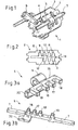
- FIG. 1 shows a locking mechanism 1 in a perspective view.
- the locking mechanism 1 comprises a cam plate 2 with a gate section 3 and a locking device 4 with a blocking element 5 and a locking lever 6.
- the blocking element 5 is arranged movably on a shaft 7, which runs parallel to a selector shaft, not shown here. In the illustrated position of the locking lever 6, against which the locking device 5, which is movable axially relative to the switching shaft, a movement of the locking device is possible only in one direction.
- Figure 2 shows the link plate 2 with the gate section 3 in plan view.
- the gate section comprises four parallel shift gates 8, 9, 10, 11, which each have an equal distance to each other.
- the link plate can be used for a manual transmission with 6 gears and a reverse gear, which is illustrated by the attached at the ends of the shift gates numbers R and 1 to 6.
- Figure 2 shows a rigidly connected to the switching shaft guide pin 12, which engages from below through the plane of Figure 2 through the link plate, at the upper end of the shift gate 9. In this position of the guide pin 12, the 1st gear of the gearbox is connected.
- a Wählgasse 13 sen sen perpendicular to the shift gates 8 to 11 and connects them with each other.
- FIG. 3 a shows an embodiment of the blocking element 5 in a perspective view.
- a sleeve 14 with a cylindrical inner surface provides for the axially movable mounting of the locking element 5.
- On the sleeve 14 integrally formed is a locking comb 15 with three teeth 16, 17 and 18 and with a guide 19 which is also formed as a tooth.
- the locking device 5 comprises a stop 20 which cooperates with the locking lever 6 for axial (partial) locking.
- Figure 1 it is clear that the teeth 16, 17 and 18 of the locking element 5 reach into the selector gate 13.
- Figure 3b shows a second embodiment of the locking element 5, preferably made of two joined sheets.
- the blocking element 5 and the shaft 7 are rigidly connected, and the shaft 7 is slidably mounted parallel to the switching shaft. This advantageously results in an increased guide length of the locking element 5.
- the blocking element can also be in one piece, z. B. be executed as a casting.
- the stop 20 can be arranged as a separate part on the blocking element 5 or be an integral part of the blocking element 5.
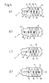
- FIGS. 4a to 4d A possible switching and dialing process is shown by way of example with reference to FIGS. 4a to 4d. Other switching and dialing procedures are analogous to the examples shown here.
- Figure 4a shows the link plate of Figure 2 with the guide pin 12 (now in another position) and with the teeth 16, 17 and 18 shown in section.
- the guide 19 is also shown in section and is located in a guide lane 21, which is an extension the selection gate 13 represents.
- the guide 19 serves to prevent rotation of the locking device 5.
- the teeth 16, 17 and 18 of the locking device 5 are arranged in the selector gate between two shift gates.
- the guide pin 12 is located in the shift gate 11 5th gear is engaged.
- Figures 4a and 4b show in conjunction, as the locking device 5 with the teeth 16, 17 and 18 and with the guide 19, the movement of the guide pin in the selector gate limited.
- the guide pin 12 is guided in the middle of Wählgasse 11 and pressed against the tooth 18. If the locking element 5 is not locked, the locking device 5 is pressed to the left until the guide 19 at a first stop 22, which defines the end of the guide lane 21, rests (see Figure 4b).
- FIG. 4b shows the blocking element 5 in a first end position. If now the guide pin along the shift gate 10 moves to insert the 4th gear, the blocking element 5, for example, due to return springs, which are not shown, return to the neutral position. It is clear that a shift back from 5th gear in the 1st or 2nd gear due to the locking element is not possible.
- Figure 4d shows the teeth 16, 17 and 18 of the locking device 5 in a second end position.
- the guide pin 12 now pushes the tooth 18 to the right through the shift gate 11 until it bears against a second stop 23 of the gate section 3.
Landscapes
- Engineering & Computer Science (AREA)
- General Engineering & Computer Science (AREA)
- Mechanical Engineering (AREA)
- Gear-Shifting Mechanisms (AREA)
Description
Die Erfindung betrifft einen Sperrmechanismus eines Schaltgetriebes zur Zwangsführung eines Kulissenstifts, der starr mit einer Schaltwelle eines Schaltgetriebes verbunden ist.The invention relates to a locking mechanism of a gearbox for positive guidance of a sliding pin, which is rigidly connected to a switching shaft of a gearbox.
Ein Sperrmechanismus der oben genannten Art ist beispielsweise aus der gattungsbildenden DE 198 57 713 DE bekannt. Der Sperrmechanismus umfasst eine Kulissenplatte mit einem Kulissenausschnitt, in den der Kulissenstift greift. Innerhalb des Kulissenausschnitts ist der Kulissenstift bewegbar angeordnet. Der Kulissenausschnitt weist eine Wählgasse sowie mehrere Schaltgassen auf, die parallel und in gleichen Abständen zueinander angeordnet sind und von der Wählgasse im Wesentlichen senkrecht gekreuzt werden. Eine Sperrvorrichtung schränkt die Bewegung des Kulissenstifts in der Wählgasse ein. So umfasst die Sperreinrichtung ein Sperrelement mit einer Nase, an der der Kulissenstift anliegt. Die Bewegbarkeit des Sperrelements wird durch zwei Anschlagzapfen begrenzt, die über der Kulissenplatte angeordnet sind. Des Weiteren umfasst die Sperrvorrichtung einen an der Schaltwelle angeformten Bund und einen Bolzen, der über ein Elektromagneten in radialer Richtung der Schaltwelle verschiebbar ist. In einer Sperrstellung hintergreift der Bolzen den Bund, so daß eine axiale Bewegung der Schaltwelle und somit des Kulissenstifts eingeschränkt ist.A locking mechanism of the above type is known for example from the generic DE 198 57 713 DE. The locking mechanism comprises a link plate with a gate section, in which engages the guide pin. Within the gate section of the guide pin is arranged movable. The gate section has a Wählgasse and a plurality of shift gates, which are arranged parallel and at equal distances from each other and are crossed by the Wählgasse substantially perpendicular. A locking device restricts the movement of the sliding pin in the selector gate. Thus, the locking device comprises a locking element with a nose against which the guide pin. The mobility of the locking element is limited by two stop pins, which are arranged above the link plate. Furthermore, the locking device comprises a collar formed on the switching shaft and a bolt which is displaceable via an electromagnet in the radial direction of the switching shaft. In a blocking position, the bolt engages behind the collar, so that an axial movement of the switching shaft and thus of the sliding pin is limited.
Die in der DE 198 57 713 DE offenbarte Sperrvorrichtung umfasst mehrere Bauteile, die genau aufeinander abgestimmt sein müssen, damit der Sperrmechanismus exakt arbeiten kann. Um eine exakte Funktionsweise des Sperrmechanismus erreichen zu können, müssen die einzelnen Bauteile innerhalb enger Fertigungstoleranzen hergestellt sein.The disclosed in DE 198 57 713 DE locking device comprises a plurality of components that must be precisely matched to each other, so that the locking mechanism can work exactly. In order to achieve an exact operation of the locking mechanism, the individual components must be manufactured within close manufacturing tolerances.
Der Erfindung liegt daher die Aufgabe zu Grunde, einen Sperrmechanismus zur Zwangsführung eines Kulissenstifts einer Schaltwelle bereitzustellen, der einen einfachen Aufbau aufweist und kostengünstig hergestellt werden kann.The invention is therefore based on the object to provide a locking mechanism for positively guiding a sliding pin of a switching shaft, which has a simple structure and can be produced inexpensively.
Die Aufgabe wird durch einen Sperrmechanismus gemäß des Anspruchs 1 gelöst. Dadurch, daß das Sperrelement in den Kulissenausschnitt hineinragt und daß der Kulissenausschnitt einen ersten und einen zweiten Anschlag umfasst, die eine erste und eine zweite Endstellung definieren, kann auf zusätzliche Anschlagzapfen über der Kulissenplatte verzichtet werden. Dabei entfällt die aufwendige Ausrichtung der Anschlagzapfen in Bezug auf die Kulissenplatte beziehungsweise in Bezug auf die Wählgasse.The object is achieved by a locking mechanism according to the
In einem bevorzugten Ausführungsbeispiel umfasst die Sperrvorrichtung einen Sperrhebel, an dem das Sperrelement in Bewegungsrichtung anliegt, wenn der Sperrhebel sich in einer Sperrposition befindet. Somit ist es möglich, das entlang der Wählgasse bewegbare Sperrelement auch in einer zwischen den beiden Endstellungen liegenden Stellung zu arretieren beziehungsweise zu sperren. Dadurch kann be ispielsweise sichergestellt werden, daß der Kulissenstift von einer Schaltgasse mit zwei benachbarten Schaltgassen nur in einer der beiden benachbarten Schaltgassen geführt werden kann.In a preferred embodiment, the locking device comprises a locking lever on which the locking element abuts in the direction of movement when the locking lever is in a locking position. Thus, it is possible to lock or block the movable along the selector gate blocking element also in a position lying between the two end positions. As a result, it can be ensured be ispielsweise that the guide pin can be performed by a shift gate with two adjacent shift gates only in one of the two adjacent shift lanes.
Vorzugsweise umfasst das Sperrelement einen Sperrkamm mit mehreren, in einer Reihe angeordneten Zähne, die in die Wählgasse hineinragen. Dabei kann der Sperrkamm mit seinen Zähnen einstückig ausgebildet sein, so daß eine Befestigung oder Verspannung der Zähne untereinander nicht notwendig ist. Damit die Zähne in der Wählgasse hin- und herbewegt werden können, ist die Tiefe oder Dicke der Zähne kleiner als die Breite der Wählgasse.Preferably, the blocking element comprises a barrier comb having a plurality of teeth arranged in a row, which project into the selection gate. In this case, the locking comb can be integrally formed with its teeth, so that an attachment or clamping of the teeth with each other is not necessary. So that the teeth in the selector gate can be moved back and forth, the depth or thickness of the teeth is smaller than the width of the selector gate.
Die Zähne weisen vorzugsweise jeweils eine Breite auf, die dem Abstand zwischen zwei benachbarten Schaltgassen entspricht (der Abstand soll dabei die Strecke zwischen einem seitlichen Ende einer Schaltgasse und dem angrenzenden seitlichen Ende der benachbarten Schaltgasse sein. Der Abstand der Zähne untereinander entspricht der Breite einer Schaltgasse. Somit lässt sich der Sperrkamm in der Wählgasse derart anordnen, daß die Lücke zwischen zwei benachbarten Zähnen eine ungehinderte Bewegung des Kulissenstift in einer Schaltgasse ermöglicht, die zwei Zähne jedoch gleichzeitig, soweit das Sperrelement fixiert ist, für eine exakte Führung der Kulissenstifts entlang der Schaltgasse im Kreuzungsbereich mit der Wählgasse sorgen.The teeth preferably each have a width that corresponds to the distance between two adjacent shift gates (the distance should be the distance between a lateral end of a shift gate and the adjacent lateral end of the adjacent shift gate.) corresponds to the width of a shift gate. Thus, the locking comb can be arranged in the selector gate such that the gap between two adjacent teeth allows unimpeded movement of the guide pin in a shift gate, the two teeth but at the same time, as far as the locking element is fixed, for an accurate guidance of the guide pin along the shift gate in Make crossing area with the selector gate.
In einem bevorzugten Ausführungsbeispiel ist das Sperrelement von einer Neutralstellung in die erste oder zweite Endstellung um jeweils einen Verschiebeweg bewegbar, dessen Länge der Summe der Breite einer Schaltgasse und dem Abstand zwischen zwei benachbarten Schaltgassen entspricht. In der Neutralstellung sind die Zähne derart in der Wählgasse angeordnet, daß die Lücken zwischen den Zähnen eine ungehinderte Bewegung des Kulissenstifts in den Schaltgasse zulässt. Wird mittels des Kulissenstifts die (nicht arretierte) Sperrvorrichtung in eine Richtung entlang der Wählgasse gedrückt, liegt der Kulissenstift an einem Zahn der Sperrvorrichtung an. Der mögliche Verschiebeweg ist dabei begrenzt: Der Kulissenstift kann nur in eine direkt benachbarte Schaltgasse geführt werden. Ein Führen des Kulissenstift entlang der Wählgasse in eine übernächste Schaltgasse ist nicht möglich.In a preferred embodiment, the blocking element is movable from a neutral position in the first or second end position by a respective displacement, the length of which corresponds to the sum of the width of a shift gate and the distance between two adjacent shift gates. In the neutral position, the teeth are arranged in the selector gate so that the gaps between the teeth allows unimpeded movement of the sliding pin in the shift gate. If the (non-locked) locking device is pressed in one direction along the selector gate by means of the guide pin, the guide pin abuts a tooth of the locking device. The possible displacement is limited: The guide pin can only be performed in a directly adjacent shift gate. It is not possible to guide the guide pin along the selector gate into a next but one shift gate.
Vorzugsweise weist der Sperrkamm bei einer Schaltkulisse mit n Schaltgassen wenigstens n-1 Zähne auf. Bei beispielsweise vier Schaltgassen kann der Sperrkamm somit 3 Zähne umfassen.Preferably, the barrier comb at least n-1 teeth on a shift gate with n shift gates. For example, four shift gates, the locking comb can thus comprise 3 teeth.
In der Neutralstellung können die n-1 Zähne zwischen den n Schaltgassen angeordnet sein. Bei dem Beispiel mit vier Schaltgassen ist der erste Zahn zwischen der ersten und zweiten Schaltgasse, der zweite Zahn zwischen zweiter und dritter Schaltgasse und der dritte Zahn zwischen dritter und vierter Schaltgasse angeordnet.In the neutral position, the n-1 teeth can be arranged between the n shift gates. In the example with four shift gates, the first tooth between the first and second shift gate, the second tooth between the second and third shift gate and the third tooth between the third and fourth shift gate is arranged.
In einem bevorzugten Ausführungsbeispiel kann die Sperrvorrichtung eine Führung umfassen, die in eine parallel zur Wählgasse verlaufende Führungsgasse greift.In a preferred embodiment, the locking device may comprise a guide which engages in a parallel to the selection gate extending guide lane.
Durch die Führung wird verhindert, daß sich die Sperrvorrichtung ohne Verkanten oder Verdrehen in der Wählgasse bewegen kann.By guiding it is prevented that the locking device can move without tilting or twisting in the selector gate.
Vorzugsweise ist die Führungsgasse in Verlängerung der Wählgasse angeordnet. In diesem Fall liegen die Führung und die Zähne des Sperrkamms in einer Ebene. Die Führung kann dabei die Form eines Zahns annehmen, ohne daß dieser Zahn die gleiche Breite wie die anderen Zähne aufweisen muss. Auch ist sein Abstand zu dem nächstliegenden Zahn in Grenzen wählbar.Preferably, the guide lane is arranged in extension of the selector gate. In this case, the guide and the teeth of the ridge are in a plane. The guide can take the form of a tooth, without this tooth must have the same width as the other teeth. Also his distance to the nearest tooth is within limits selectable.
Das Sperrelement kann durch wenigstens eine Rückstellfeder in der Neutralstellung gehalten werden. Zweckmäßig ist es, das Sperrelement zwischen zwei Rückstellfedern zu schalten. Soll das Sperrelement aus der Neutralstellung in eine der beiden Endstellungen bewegt werden, muß die Kraft der Rückstellfedern überwunden werden. Diese Kraft wird durch den Kulissenstift über einen Zahn auf das Sperrelement übertragen. Wird der Kulissenstift aus der Wählgasse in eine Schaltgasse geführt, so daß der Kulissenstift nicht mehr an dem Zahn anliegt, drücken die Rückstellfedern das Sperrelement wieder in die Neutralstellung. Die Neutralstellung wird in diesem Fall durch das Kräftegleichgewicht der Rückstellfedern definiert. Bevorzugt wird eine definierte Neutralstellung, die unabhängig von den Toleranzen und dem Verschleiß der Feder ist.The blocking element can be held in the neutral position by at least one restoring spring. It is useful to switch the blocking element between two return springs. If the blocking element to be moved from the neutral position in one of the two end positions, the force of the return springs must be overcome. This force is transmitted through the guide pin via a tooth on the blocking element. If the guide pin out of the selector gate in a shift gate, so that the guide pin is no longer applied to the tooth, the return springs press the locking element back into the neutral position. The neutral position is defined in this case by the balance of forces of the return springs. Preferred is a defined neutral position, which is independent of the tolerances and the wear of the spring.
Um solch eine Neutralstellung auf andere Weise zu definieren, kann wenigstens ein Anschlag für die Rückstellfeder vorgesehen sein. Liegt die Rückstellfeder an diesem Anschlag an, befindet sich das Sperrelement in einer geometrisch bestimmten Neutralstellung. Diese ist unabhängig von dem Kräftegleichgewicht der Rückstellfedern.In order to define such a neutral position in another way, at least one stop for the return spring can be provided. If the return spring abuts on this stop, the blocking element is in a geometrically determined neutral position. This is independent of the balance of power of the return springs.
Vorzugweise weist der Kulissenausschnitt der Kulissenplatte an den zwei Enden der Wählgasse Verlängerungen auf, so daß die Wählgasse über den Kreuzungspunkt mit einer ersten Schaltgasse und über den Kreuzungspunkt mit einer letzten Schaltgasse hinausgeht. Die Verlängerung weist wenigstens eine Länge auf, die mindestens dem Abstand benachbarter Schaltgassen entspricht. Somit kann eine Verlängerung einen äußeren Zahn einer Sperrkamms, dessen Zähne jeweils eine Breite aufweisen, die dem Abstand benachbarter Schaltgassen entspricht, vollständig aufnehmen, so daß der äußere Zahn die Bewegung eines Kulissenstifts in der ersten beziehungsweise letzten Schaltgasse nicht behindert.Preferably, the gate section of the cam plate at the two ends of Wählgasse extensions, so that the selector gate beyond the crossing point with a first shift gate and beyond the crossing point with a last shift gate. The extension has at least one length which corresponds at least to the distance between adjacent shift lanes. Thus, an extension of an outer tooth of a locking comb, whose teeth each have a width corresponding to the distance of adjacent shift lanes, completely absorb, so that the outer tooth does not hinder the movement of a sliding pin in the first and last shift gate.
Anhand eines in den Figuren dargestellten Ausführungsbeispiels wird die Erfindung näher beschrieben. Es zeigen:
Figur 1- eine perspektivische Ansicht eines Ausführungsbeispiels des erfindungsgemäßen Sperrmechanismus;
Figur 2- eine Draufsicht einer Kulissenplatte;
Figur 3- zwei verschiedene Ausführungsformen der Sperrvorrichtung; und
Figur 4- die Kulissenplatte der
Figur 2 mit der im Schnitt dargestellten Sperrvorrichtung, wobei die Sperrvorrichtung verschiedene Stellungen einnimmt.
- FIG. 1
- a perspective view of an embodiment of the locking mechanism according to the invention;
- FIG. 2
- a plan view of a link plate;
- FIG. 3
- two different embodiments of the locking device; and
- FIG. 4
- the link plate of Figure 2 with the locking device shown in section, wherein the locking device occupies different positions.
Figur 1 zeigt ein Sperrmechanismus 1 in einer perspektivischen Ansicht. Der Sperrmechanismus 1 umfasst eine Kulissenplatte 2 mit einem Kulissenausschnitt 3 und eine Sperrvorrichtung 4 mit einem Sperrelement 5 und einem Sperrhebel 6. Das Sperrelement 5 ist bewegbar auf einer Welle 7 angeordnet, die parallel zu einer hier nicht dargestellten Schaltwelle verläuft. In der dargestellten Stellung des Sperrhebels 6, an dem die axial zur Schaltwelle bewegbare Sperrvorrichtung 5 anliegt, ist eine Bewegung der Sperrvorrichtung nur in eine Richtung möglich.FIG. 1 shows a
Figur 2 zeigt die Kulissenplatte 2 mit dem Kulissenausschnitt 3 in der Draufsicht. Der Kulissenausschnitt umfasst vier parallel verlaufende Schaltgassen 8, 9, 10, 11, die zueinander jeweils einen gleichen Abstand aufweisen. Die Kulissenplatte kann für ein Schaltgetriebe mit 6 Gängen und einem Rückwärtsgang verwendet werden, was durch die an den Enden der Schaltgassen angebrachten Ziffern R und 1 bis 6 verdeutlicht wird. Figur 2 zeigt ein starr mit der Schaltwelle verbundener Kulissenstift 12, der von unten durch die Zeichenebene der Figur 2 durch die Kulissenplatte greift, an dem oberen Ende der Schaltgasse 9. In dieser Position des Kulissenstifts 12 ist der 1. Gang des Schaltgetriebes geschaltet. Eine Wählgasse 13 verläuft sen krecht zu den Schaltgassen 8 bis 11 und verbindet diese untereinander.Figure 2 shows the
Figur 3a zeigt eine Ausführungsform des Sperrelements 5 in perspektivischer Ansicht. Eine Buchse 14 mit einer zylinderförmigen Innenfläche sorgt für die axial bewegbare Lagerung des Sperrelements 5. An der Buchse 14 einstückig angeformt ist ein Sperrkamm 15 mit drei Zähnen 16, 17 und 18 sowie mit einer Führung 19, die ebenfalls als Zahn ausgebildet ist. Des Weiteren umfasst die Sperrvorrichtung 5 einen Anschlag 20, der mit dem Sperrhebel 6 zur axialen (Teil-)Arretierung zusammenwirkt. In Zusammenschau mit Figur 1 wird deutlich, daß die Zähne 16, 17 und 18 des Sperrelementes 5 in die Wählgasse 13 hineingreifen.FIG. 3 a shows an embodiment of the blocking
Figur 3b zeigt eine zweite Ausführungsform des Sperrelements 5, vorzugsweise gefertigt aus zwei gefügten Blechen. Bei dieser sind das Sperrelement 5 und die Welle 7 starr verbunden, und die Welle 7 ist parallel zur Schaltwelle verschiebbar gelagert. Dadurch ergibt sich vorteilhaft eine erhöhte Führungslänge des Sperrelements 5. Das Sperrelement kann aber auch einstückig, z. B. als Gußteil, ausgeführt sein. Ebenso kann der Anschlag 20 als separates Teil am Sperrelement 5 angeordnete sein oder integraler Bestandteil des Sperrelements 5 sein.Figure 3b shows a second embodiment of the
Anhand der Figuren 4a bis 4d wird exemplarisch ein möglicher Schalt- und Wählverlauf gezeigt. Andere Schalt- und Wählabläufe erfolgen analog den hier gezeigten Beispielen.A possible switching and dialing process is shown by way of example with reference to FIGS. 4a to 4d. Other switching and dialing procedures are analogous to the examples shown here.
Figur 4a zeigt die Kulissenplatte der Figur 2 mit dem Kulissenstift 12 (nun in anderer Position) und mit den im Schnitt dargestellten Zähnen 16, 17 und 18. Die Führung 19 ist ebenfalls im Schnitt dargestellt und befindet sich in einer Führungsgasse 21, die eine Verlängerung der Wählgasse 13 darstellt. Die Führung 19 dient zur Verdrehsicherung der Sperrvorrichtung 5. Die Zähne 16, 17 und 18 der Sperrvorrichtung 5 sind in der Wählgasse jeweils zwischen zwei Schaltgassen angeordnet. Der Kulissenstift 12 liegt in der Schaltgasse 11 der 5. Gang ist eingelegt.Figure 4a shows the link plate of Figure 2 with the guide pin 12 (now in another position) and with the
Die Figuren 4a und 4b zeigen in Zusammenschau, wie die Sperrvorrichtung 5 mit den Zähnen 16, 17 und 18 sowie mit der Führung 19 die Bewegung des Kulissenstifts in der Wählgasse beschränkt. Soll beispielsweise ausgehend vom 5. Gang in den 4. Gang geschaltet werden, wird der Kulissenstift 12 in die Mitte der Wählgasse 11 geführt und gegen den Zahn 18 gedrückt. Wenn das Sperrelement 5 nicht arretiert ist, wird die Sperrvorrichtung 5 nach links gedrückt, bis die Führung 19 an einem ersten Anschlag 22, der das Ende der Führungsgasse 21 definiert, anliegt (vgl. Figur 4b). Figur 4b zeigt das Sperrelement 5 in einer ersten Endstellung. Wird nun der Kulissenstift entlang der Schaltgasse 10 zum Einlegen des 4. Gangs bewegt, kann das Sperrelement 5 beispielsweise aufgrund von Rückstellfedern, die nicht dargestellt sind, wieder in die Neutralstellung zurückkehren. Es wird deutlich, daß ein Zurückschalten vom 5. Gang in den 1. oder 2. Gang aufgrund des Sperrelements nicht möglich ist.Figures 4a and 4b show in conjunction, as the
Figur 4d zeigt die Zähne 16, 17 und 18 der Sperrvorrichtung 5 in einer zweiten Endstellung. Hier wird von dem 4. Gang in den 5. Gang geschaltet. Der Kulissenstift 12 schiebt den Zahn 18 nun nach rechts durch die Schaltgasse 11, bis er an einem zweiten Anschlag 23 des Kulissenausschnitts 3 anliegt.Figure 4d shows the
Claims (14)
- Locking mechanism (1) for a manual gearbox for restricted guidance of a gate pin (12) which is rigidly connected to a shift shaft of a manual gearbox, comprising:a) a gate plate (2) having a gate cut-out (3) which comprises one selector slot (13) and a plurality of shift slots (8, 9, 10, 11),- the shift slots (8, 9, 10, 11) being arranged substantially parallel to and at equal distances from one another and being crossed substantially perpendicularly by the selector slot (13), and- the gate pin (12) engaging into the gate cut-out (3);b) a locking device (4) for restricting the movement of the gate pin (12) in the selector slot (13), having at least one locking element (5) which as arranged such that it can move along the selector slot (13) between a first and a second end position,characterized in that
the locking element (5) projects into the gate cut-out (3), the locking element (5) bearing against a first stop (22) of the gate cut-out (3) in the first end position and bearing against a second stop (23) of the gate cut-out (3) in the second end position. - Locking mechanism (1) according to Claim 1,
characterized in that
the locking device (4) comprises at least one locking lever (6), against which the locking element (5) bears in the longitudinal direction of the selector slot (13) when the locking lever (6) is in a locking position. - Locking mechanism (1) according to Claim 1 or 2,
characterized in that
the locking element (5) comprises a locking comb (15) with a plurality of teeth (16, 17, 18) which are arranged in a row and project into the selector slot (13). - Locking mechanism (1) according to Claim 3,
characterized in that
the teeth (16, 17, 18) are each of equal width and are at an equal distance from adjacent teeth, the width of a tooth corresponding to the distance between two shift slots (8, 9, 10, 11) and the distance between the teeth (16, 17, 18) corresponding to the width of a shift slot (8, 9, 10, 11). - Locking mechanism (1) according to one of Claims 1 to 4,
characterized in that
from a neutral position, the locking element (5) can be moved through a displacement travel into the first or into the second end position, which displacement travel is in each case composed of the width of a shift slot and the distance between two adjacent shift slots. - Locking mechanism (1) according to one of Claims 3 to 5,
characterized in that
for n shift slots, the locking comb (15) has at least n-1 teeth. - Locking mechanism (1) according to Claim 6,
characterized in that
in the neutral position of the locking comb (15), the n-1 teeth are arranged between the first shift slot (8) and the n-th shift slot (11). - Locking mechanism (1) according to one of Claims 1 to 7,
characterized in that
the locking element (5) comprises a guide (19) which engages into a guide slot (21), which runs parallel to the selector slot (13), of the gate plate (2). - Locking mechanism (1) according to Claim 8,
characterized in that
the guide slot (21) is arranged as an extension of the selector slot (13). - Locking mechanism (1) according to one of claims 1 to 9,
characterized in that
the locking element (5) is held in the neutral position by means of at least one return spring. - Locking mechanism (1) according to Claim 10,
characterized in that
the neutral position is defined by means of a stop for the return spring. - Locking mechanism (1) according to one of the preceding claims,
characterized in that
the locking element (5) is fixedly connected to the shaft (7), and the shaft (7) is mounted in a longitudinally displaceable manner. - Locking mechanism (1) according to Claim 12,
characterized in that
the locking element (5) and the shaft (7) are embodied in one piece. - Locking mechanism (1) according to one of the preceding claims,
characterized in that
the gate cut-out (3) has an extension at each of the two ends of the selector slot (13), which extension extends, respectively, beyond the point of intersection with the first shift slot (8) or beyond the point of intersection with the n-th shift slot (11), each extension extending at least over a length which corresponds to the distance between two adjacent shift slots.
Priority Applications (2)
| Application Number | Priority Date | Filing Date | Title |
|---|---|---|---|
| DE50304591T DE50304591D1 (en) | 2003-09-26 | 2003-09-26 | Locking mechanism of a manual transmission |
| EP20030103577 EP1519085B1 (en) | 2003-09-26 | 2003-09-26 | Locking mechanism for a manual gearbox |
Applications Claiming Priority (1)
| Application Number | Priority Date | Filing Date | Title |
|---|---|---|---|
| EP20030103577 EP1519085B1 (en) | 2003-09-26 | 2003-09-26 | Locking mechanism for a manual gearbox |
Publications (2)
| Publication Number | Publication Date |
|---|---|
| EP1519085A1 EP1519085A1 (en) | 2005-03-30 |
| EP1519085B1 true EP1519085B1 (en) | 2006-08-09 |
Family
ID=34178599
Family Applications (1)
| Application Number | Title | Priority Date | Filing Date |
|---|---|---|---|
| EP20030103577 Expired - Lifetime EP1519085B1 (en) | 2003-09-26 | 2003-09-26 | Locking mechanism for a manual gearbox |
Country Status (2)
| Country | Link |
|---|---|
| EP (1) | EP1519085B1 (en) |
| DE (1) | DE50304591D1 (en) |
Cited By (3)
| Publication number | Priority date | Publication date | Assignee | Title |
|---|---|---|---|---|
| DE102008000970A1 (en) | 2008-04-03 | 2009-10-08 | Zf Friedrichshafen Ag | Switching device for gearbox of vehicle, has blocking element designed as single locking tooth, and axial displacement of pin takes place during selection movement in all gear positions |
| DE102012015619A1 (en) | 2012-08-07 | 2013-03-07 | Daimler Ag | Gear box actuator unit for actuating manual transmission of motor car, has link element comprising locking element and linking path, where locking element is formed as locking sleeve and partially arranged in or on link element |
| CN105829779A (en) * | 2013-12-18 | 2016-08-03 | 舍弗勒技术股份两合公司 | Method for determining a reference position, preferably for a transmission actuator of a motor vehicle, and a transmission actuator for a motor vehicle transmission |
Families Citing this family (4)
| Publication number | Priority date | Publication date | Assignee | Title |
|---|---|---|---|---|
| DE102006017158B4 (en) * | 2005-05-07 | 2022-04-21 | Schaeffler Technologies AG & Co. KG | Transmission actuator for a motor vehicle transmission device, motor vehicle transmission device with a transmission actuator and motor vehicle drive train with a motor vehicle transmission device |
| JP4809629B2 (en) * | 2005-05-25 | 2011-11-09 | アイシン・エーアイ株式会社 | Shifting operation device |
| DE102013202273A1 (en) * | 2013-02-13 | 2014-08-14 | Zf Friedrichshafen Ag | Switching device with a slotted guide for a vehicle transmission |
| WO2021040541A1 (en) * | 2019-08-30 | 2021-03-04 | Johnson Alan Blake | An attachment for the shifter of a gearbox of a vehicle |
Family Cites Families (4)
| Publication number | Priority date | Publication date | Assignee | Title |
|---|---|---|---|---|
| US2684600A (en) * | 1949-12-28 | 1954-07-27 | Daimler Benz Ag | Shifting mechanism for transmissions |
| US4633728A (en) * | 1985-09-05 | 1987-01-06 | Ford Motor Company | Gear selector control for manual transmission |
| DE3913269A1 (en) * | 1989-04-22 | 1990-10-31 | Ford Werke Ag | SWITCHING DEVICE FOR INTERCHANGEABLE GEARBOXES OF MOTOR VEHICLES |
| JPH11270672A (en) * | 1997-12-18 | 1999-10-05 | Aft Atlas Fahrzeugtechnik Gmbh | Operating device |
-
2003
- 2003-09-26 DE DE50304591T patent/DE50304591D1/en not_active Expired - Lifetime
- 2003-09-26 EP EP20030103577 patent/EP1519085B1/en not_active Expired - Lifetime
Cited By (4)
| Publication number | Priority date | Publication date | Assignee | Title |
|---|---|---|---|---|
| DE102008000970A1 (en) | 2008-04-03 | 2009-10-08 | Zf Friedrichshafen Ag | Switching device for gearbox of vehicle, has blocking element designed as single locking tooth, and axial displacement of pin takes place during selection movement in all gear positions |
| DE102012015619A1 (en) | 2012-08-07 | 2013-03-07 | Daimler Ag | Gear box actuator unit for actuating manual transmission of motor car, has link element comprising locking element and linking path, where locking element is formed as locking sleeve and partially arranged in or on link element |
| CN105829779A (en) * | 2013-12-18 | 2016-08-03 | 舍弗勒技术股份两合公司 | Method for determining a reference position, preferably for a transmission actuator of a motor vehicle, and a transmission actuator for a motor vehicle transmission |
| CN105829779B (en) * | 2013-12-18 | 2018-09-21 | 舍弗勒技术股份两合公司 | Method of determining a reference position of a transmission actuator and transmission actuator |
Also Published As
| Publication number | Publication date |
|---|---|
| EP1519085A1 (en) | 2005-03-30 |
| DE50304591D1 (en) | 2006-09-21 |
Similar Documents
| Publication | Publication Date | Title |
|---|---|---|
| EP0408932B1 (en) | Locking device for adjustable vehicle seats | |
| EP2175176B1 (en) | Shifting device for a multiple gear gearbox with a locking device | |
| DE102008060167A1 (en) | Valve gear of an internal combustion engine | |
| DE2313366A1 (en) | SHIFTING MECHANISM FOR GEAR BOXES | |
| DE60016257T2 (en) | Draw key transmission | |
| DE19805924A1 (en) | transmission | |
| DE69123335T2 (en) | Device for adjusting the length of a rod, in particular a rod for the operation of a vehicle lock | |
| DE3408090C2 (en) | ||
| EP0846797B1 (en) | Warp knitting machine with Jacquard-inlay bar | |
| EP1519085B1 (en) | Locking mechanism for a manual gearbox | |
| DE2727833C2 (en) | Sliding mechanism of a switching device for a motor vehicle transmission | |
| DE2653035C3 (en) | Switching device for a motor vehicle change gearbox | |
| DE3125632C1 (en) | Switching device for a change gear, in particular in motor vehicles | |
| EP0412279A2 (en) | Gear change device for a stepped toothed gearing of an automotive vehicle | |
| DE4424543A1 (en) | Gear-lever arrangement for a gearbox | |
| DE1650820B1 (en) | SHIFTING DEVICE FOR TWO SHIFTER FORKS TO ENGAGE WITH TWO SLIDING SLEEVES OF A GEARBOX | |
| EP2179200B1 (en) | Shifting device for a transmission of a motor vehicle having a locking device | |
| EP3108159B1 (en) | Shifting arrangement for a transmission | |
| EP1236936B1 (en) | Shift lock mechanism | |
| DE1163688B (en) | Switching and locking device for gearboxes in motor vehicles | |
| WO2016034336A1 (en) | Camshaft with a shifting gate | |
| EP0752549B1 (en) | Shift mechanism for vehicle transmissions | |
| DE102008000970A1 (en) | Switching device for gearbox of vehicle, has blocking element designed as single locking tooth, and axial displacement of pin takes place during selection movement in all gear positions | |
| DE102018206392A1 (en) | SWITCHING DEVICE FOR IMPLEMENTING GEAR CHANGE IN A VEHICLE GEARBOX | |
| DE2926928C2 (en) | "Pattern gear for warp knitting machines or the like. |
Legal Events
| Date | Code | Title | Description |
|---|---|---|---|
| PUAI | Public reference made under article 153(3) epc to a published international application that has entered the european phase |
Free format text: ORIGINAL CODE: 0009012 |
|
| 17P | Request for examination filed |
Effective date: 20040317 |
|
| AK | Designated contracting states |
Kind code of ref document: A1 Designated state(s): AT BE BG CH CY CZ DE DK EE ES FI FR GB GR HU IE IT LI LU MC NL PT RO SE SI SK TR |
|
| AX | Request for extension of the european patent |
Extension state: AL LT LV MK |
|
| AKX | Designation fees paid |
Designated state(s): DE FR GB |
|
| GRAP | Despatch of communication of intention to grant a patent |
Free format text: ORIGINAL CODE: EPIDOSNIGR1 |
|
| GRAS | Grant fee paid |
Free format text: ORIGINAL CODE: EPIDOSNIGR3 |
|
| GRAA | (expected) grant |
Free format text: ORIGINAL CODE: 0009210 |
|
| AK | Designated contracting states |
Kind code of ref document: B1 Designated state(s): DE FR GB |
|
| REG | Reference to a national code |
Ref country code: GB Ref legal event code: FG4D Free format text: NOT ENGLISH |
|
| REF | Corresponds to: |
Ref document number: 50304591 Country of ref document: DE Date of ref document: 20060921 Kind code of ref document: P |
|
| GBT | Gb: translation of ep patent filed (gb section 77(6)(a)/1977) |
Effective date: 20061115 |
|
| ET | Fr: translation filed | ||
| PLBE | No opposition filed within time limit |
Free format text: ORIGINAL CODE: 0009261 |
|
| STAA | Information on the status of an ep patent application or granted ep patent |
Free format text: STATUS: NO OPPOSITION FILED WITHIN TIME LIMIT |
|
| 26N | No opposition filed |
Effective date: 20070510 |
|
| REG | Reference to a national code |
Ref country code: FR Ref legal event code: PLFP Year of fee payment: 13 |
|
| REG | Reference to a national code |
Ref country code: FR Ref legal event code: PLFP Year of fee payment: 14 |
|
| REG | Reference to a national code |
Ref country code: FR Ref legal event code: PLFP Year of fee payment: 15 |
|
| REG | Reference to a national code |
Ref country code: FR Ref legal event code: PLFP Year of fee payment: 16 |
|
| PGFP | Annual fee paid to national office [announced via postgrant information from national office to epo] |
Ref country code: DE Payment date: 20190813 Year of fee payment: 17 Ref country code: FR Payment date: 20190819 Year of fee payment: 17 |
|
| PGFP | Annual fee paid to national office [announced via postgrant information from national office to epo] |
Ref country code: GB Payment date: 20190827 Year of fee payment: 17 |
|
| REG | Reference to a national code |
Ref country code: DE Ref legal event code: R119 Ref document number: 50304591 Country of ref document: DE |
|
| GBPC | Gb: european patent ceased through non-payment of renewal fee |
Effective date: 20200926 |
|
| PG25 | Lapsed in a contracting state [announced via postgrant information from national office to epo] |
Ref country code: FR Free format text: LAPSE BECAUSE OF NON-PAYMENT OF DUE FEES Effective date: 20200930 Ref country code: DE Free format text: LAPSE BECAUSE OF NON-PAYMENT OF DUE FEES Effective date: 20210401 |
|
| PG25 | Lapsed in a contracting state [announced via postgrant information from national office to epo] |
Ref country code: GB Free format text: LAPSE BECAUSE OF NON-PAYMENT OF DUE FEES Effective date: 20200926 |