EP1518700A1 - Tintenstrahldrucker - Google Patents
Tintenstrahldrucker Download PDFInfo
- Publication number
- EP1518700A1 EP1518700A1 EP04255701A EP04255701A EP1518700A1 EP 1518700 A1 EP1518700 A1 EP 1518700A1 EP 04255701 A EP04255701 A EP 04255701A EP 04255701 A EP04255701 A EP 04255701A EP 1518700 A1 EP1518700 A1 EP 1518700A1
- Authority
- EP
- European Patent Office
- Prior art keywords
- recording medium
- conveyance belt
- recording apparatus
- fabric
- inkjet recording
- Prior art date
- Legal status (The legal status is an assumption and is not a legal conclusion. Google has not performed a legal analysis and makes no representation as to the accuracy of the status listed.)
- Granted
Links
- 239000004744 fabric Substances 0.000 claims description 38
- 239000011347 resin Substances 0.000 claims description 11
- 229920005989 resin Polymers 0.000 claims description 11
- JOYRKODLDBILNP-UHFFFAOYSA-N Ethyl urethane Chemical compound CCOC(N)=O JOYRKODLDBILNP-UHFFFAOYSA-N 0.000 claims description 6
- 229920001296 polysiloxane Polymers 0.000 claims 2
- 239000000853 adhesive Substances 0.000 abstract description 9
- 230000001070 adhesive effect Effects 0.000 abstract description 9
- 230000010287 polarization Effects 0.000 description 17
- 239000002245 particle Substances 0.000 description 14
- 239000012790 adhesive layer Substances 0.000 description 13
- 238000006073 displacement reaction Methods 0.000 description 11
- 238000012937 correction Methods 0.000 description 10
- 239000010410 layer Substances 0.000 description 5
- 239000000463 material Substances 0.000 description 5
- 238000000034 method Methods 0.000 description 5
- 239000004800 polyvinyl chloride Substances 0.000 description 4
- 229920000915 polyvinyl chloride Polymers 0.000 description 4
- 239000000758 substrate Substances 0.000 description 4
- 238000004804 winding Methods 0.000 description 4
- 238000007639 printing Methods 0.000 description 3
- 229920002379 silicone rubber Polymers 0.000 description 3
- 239000004945 silicone rubber Substances 0.000 description 3
- 239000004753 textile Substances 0.000 description 3
- 230000000007 visual effect Effects 0.000 description 3
- 238000011156 evaluation Methods 0.000 description 2
- 238000004519 manufacturing process Methods 0.000 description 2
- 238000005259 measurement Methods 0.000 description 2
- 239000004033 plastic Substances 0.000 description 2
- 229920003023 plastic Polymers 0.000 description 2
- -1 polyethylene Polymers 0.000 description 2
- 238000000926 separation method Methods 0.000 description 2
- 238000012360 testing method Methods 0.000 description 2
- 239000002759 woven fabric Substances 0.000 description 2
- 229920000742 Cotton Polymers 0.000 description 1
- 241000668842 Lepidosaphes gloverii Species 0.000 description 1
- 239000004698 Polyethylene Substances 0.000 description 1
- 239000004809 Teflon Substances 0.000 description 1
- 229920006362 Teflon® Polymers 0.000 description 1
- 230000015572 biosynthetic process Effects 0.000 description 1
- 239000003795 chemical substances by application Substances 0.000 description 1
- 239000000356 contaminant Substances 0.000 description 1
- 230000002950 deficient Effects 0.000 description 1
- 230000008021 deposition Effects 0.000 description 1
- 239000000428 dust Substances 0.000 description 1
- 239000000835 fiber Substances 0.000 description 1
- 239000011521 glass Substances 0.000 description 1
- 238000007646 gravure printing Methods 0.000 description 1
- 238000003475 lamination Methods 0.000 description 1
- 229920000515 polycarbonate Polymers 0.000 description 1
- 239000004417 polycarbonate Substances 0.000 description 1
- 229920000728 polyester Polymers 0.000 description 1
- 229920000573 polyethylene Polymers 0.000 description 1
- 229920001343 polytetrafluoroethylene Polymers 0.000 description 1
- 239000004810 polytetrafluoroethylene Substances 0.000 description 1
- 238000007650 screen-printing Methods 0.000 description 1
- 239000000126 substance Substances 0.000 description 1
- 238000010408 sweeping Methods 0.000 description 1
- 238000012546 transfer Methods 0.000 description 1
- 238000011144 upstream manufacturing Methods 0.000 description 1
- 238000005406 washing Methods 0.000 description 1
- XLYOFNOQVPJJNP-UHFFFAOYSA-N water Substances O XLYOFNOQVPJJNP-UHFFFAOYSA-N 0.000 description 1
Images
Classifications
-
- B—PERFORMING OPERATIONS; TRANSPORTING
- B41—PRINTING; LINING MACHINES; TYPEWRITERS; STAMPS
- B41J—TYPEWRITERS; SELECTIVE PRINTING MECHANISMS, i.e. MECHANISMS PRINTING OTHERWISE THAN FROM A FORME; CORRECTION OF TYPOGRAPHICAL ERRORS
- B41J11/00—Devices or arrangements of selective printing mechanisms, e.g. ink-jet printers or thermal printers, for supporting or handling copy material in sheet or web form
- B41J11/007—Conveyor belts or like feeding devices
Definitions
- the present invention relates to an inkjet recording apparatus, particularly to an inkjet recording apparatus wherein a fabric of low rigidity that creases easily is used as a main recording medium, the inkjet recording apparatus comprising a conveyance belt.
- the textile printing industry uses a fabric of low rigidity as a main recording medium, and the material woven of plastics (polyvinyl chloride), in addition to paper is utilized in the sign display industry.
- a material of low rigidity is used as a recording medium, the recording medium is conveyed generally in close contact with the conveyance belt.
- the inkjet recording apparatus where the recording medium is conveyed in close contact with the conveyance belt includes the commonly known inkjet recording apparatus, wherein an adhesive layer using such an upholstering agent as water soluble resin, pressure sensitive resin and heat sensitive resin, and adhesive sheet is formed on the surface of the conveyance belt, and the recording medium is conveyed in close contact with this adhesive layer (See Patent Document 1, for example).
- inkjet recording apparatus where paper as a recording medium is conveyed by a conveyance belt to record an image
- This inkjet recording apparatus has an electrostatic generator arranged on the bottom of the conveyance belt to charge the conveyance belt and to suck a recording medium electrostatically (See Patent Document 2, for example).
- This inkjet recording apparatus uses an electrostatic generator to charge the conveyance belt electrostatically, and paper is supported by the charged belt, whereby paper is sucked by the conveyor by contact charging.
- Patent Document 1 In the inkjet recording apparatus (Patent Document 1) having a conveyance belt provided with a prior art adhesive layer, irregularities are produced on the surface due to repeated adhesion and separation of the recording medium from the conveyance belt; hence, the adhesive strength is reduced by the deposition of dust and contaminants. Thus, the adhesive must be removed for washing at least once in a few months, and adhesive must be applied again. This has taken much time and effort, according to the prior art.
- the recording medium is brought in close contact with the conveyance belt by the adhesive layer alone, and the adhesive layer has a high degree of adhesive strength. Once the recording medium is adhered to the conveyance belt, the displacement of the recording medium cannot be corrected, with the result that adhesion and separation are repeated, and much time and effort are required, according to the prior art.
- Patent Document 2 In the inkjet recording apparatus (Patent Document 2) equipped with a conventional electrostatic generator, even when the recording medium impervious to electric charging, including such a fabric such as cotton and silk fabrics or such a woven fabric polyvinyl chloride fabric, is supported by a conveyance belt charged by an electrostatic generator, the recording medium is not sucked by the conveyance belt, so that the recording medium slips on the conveyance belt and accurate conveyance cannot be achieved. This has resulted in production of a defective image, according to this prior art.
- the aforementioned prior art inkjet recording apparatus is subject to such a restriction that the conveyance belt is made of the polycarbonate or polyethylene that is susceptible to electrostatic charge.
- the principle of electrostatic suction is based on Coulomb force, and electrostatic suction force is damped by the function of the distance between the conveyance belt and recording medium. Accordingly, the conveyance belt has a thickness of about 0.1 through 0.2 mm. However, if the thickness is small, the durability of the conveyance belt is reduced so that the conveyance belt must be replaced frequently. This has required much time and effort.
- an object of the present invention to provide an inkjet recording apparatus capable of completely sucking the recording medium onto the conveyance belt and ensuring accurate conveyance without requiring much time and effort.
- the inkjet recording apparatus of the present invention comprises a conveyance belt for supporting and transporting a recording medium, and an electrostatic generator for generating electrostatic suction force to suck the aforementioned recording medium, wherein at least the recording medium contacting surface of the conveyance belt in contact with the recording medium is adhesive.
- the fabric is kept in close contact with the conveyance belt by the adhesion of the recording medium contact surface; therefore, the recording medium is thoroughly sucked by the conveyance belt through polarization of electric charge, even if fabric impervious to electric charging is utilized.
- the fabric is defined as the entire woven fabric, including such chemical fibers as polyvinyl chloride or polyester.
- the adhesion of the recording medium contact surface can be kept to such a level that the fabric is held in close contact with the conveyance belt, without causing the fabric to be creased.
- the recording medium contact surface of the conveyance belt has a predetermined adhesion, and the recording medium is kept in close contact with the conveyance belt charged by the electrostatic generator.
- the recording medium is sucked by the conveyance belt through polarization of electric charge, even if fabric impervious to electric charging is utilized. This arrangement ensures accurate conveyance of the recording medium, hence provides a satisfactory image.
- the recording medium can be polarized. This arrangement allows the conveyance belt to have a certain thickness, and ensures excellent durability of the conveyance belt, reduced frequency of conveyance belt replacement and minimized time and effort for conveyance belt replacement.
- the adhesion of the recording medium contact surface can be kept to such a level that the recording medium is held in close contact with the conveyance belt, without causing the recording medium to be creased.
- This configuration ensures easy correction of the displacement of the recording medium, and hence saves the time and effort of separating the recording medium in close contact with the conveyance belt and bringing it in contact again.
- the adhesion of recording medium contact surface of the conveyance belt is 0.02 N/25 mm or more.
- the recording medium is thoroughly sucked by the conveyance belt charged by the electrostatic generator, and the recording medium is sucked sufficiently by the conveyance belt through polarization of the electric charge of the recording medium.
- This arrangement ensures accurate conveyance of the recording medium, hence provides a satisfactory image.
- adhesion does not exceed 1 N/25 mm. This permits easy correction of the displacement of the recording medium, and hence saves the time and effort of separating the recording medium in close contact with the conveyance belt and bringing it in contact again.
- the recording medium contact surface of the aforementioned conveyance belt is designed in a flat form, without allowing the recording medium to become loose.
- This arrangement ensures that the recording medium is firmly kept in contact with the conveyance belt charged by the electrostatic generator, and the recording medium is sucked sufficiently by the conveyance belt through polarization of the electric charge of the recording medium, with the result that accurate conveyance of the recording medium, and hence a satisfactory image are provided.
- the recording medium contact surface is made of a silicone rubber and has a predetermined adhesion. This arrangement ensures that the recording medium is firmly kept in contact with the conveyance belt charged by the electrostatic generator, and the recording medium is sucked sufficiently by the conveyance belt through polarization of the electric charge of the recording medium, with the result that accurate conveyance of the recording medium, and hence a satisfactory image are provided.
- the recording medium can be polarized. This arrangement allows the conveyance belt to have a certain thickness, and ensures excellent durability of the conveyance belt, reduced frequency of conveyance belt replacement and minimized time and effort for conveyance belt replacement.
- the adhesion of the recording medium contact surface can be kept to such a level that the recording medium is held in close contact with the conveyance belt, without causing the recording medium to be creased. This configuration ensures easy correction of the displacement of the recording medium, and hence saves the time and effort.
- the recording medium contact surface is made of a urethane based resin, and has a predetermined adhesion. This arrangement ensures that the recording medium is firmly kept in contact with the conveyance belt charged by the electrostatic generator, and the recording medium is sucked sufficiently by the conveyance belt through polarization of the electric charge of the recording medium, with the result that accurate conveyance of the recording medium, and hence a satisfactory image are provided.
- the recording medium can be polarized. This arrangement allows the conveyance belt to have a certain thickness, and ensures excellent durability of the conveyance belt, reduced frequency of conveyance belt replacement and minimized time and effort for conveyance belt replacement.
- the adhesion of the recording medium contact surface can be kept to such a level that the recording medium is held in close contact with the conveyance belt, without causing the recording medium to be creased. This configuration ensures easy correction of the displacement of the recording medium, and hence saves the time and effort.
- electrostatic force generated on the conveyance belt by the electrostatic generator is maintained, and the recording medium kept in close contact with the conveyance belt by the adhesion of the recording medium contact surface is thoroughly sucked by the conveyance belt through polarization of electric charge, with the result that accurate conveyance of the recording medium, and hence a satisfactory image are provided.
- the recording medium contact surface has a predetermined adhesion, and the fabric is kept in close contact with the conveyance belt by the adhesion of the recording medium contact surface; therefore, the fabric is thoroughly sucked by the conveyance belt through polarization of electric charge, even if fabric impervious to electric charging is utilized, with the result that accurate conveyance of the fabric, and hence a satisfactory image are provided.
- the fabric can be polarized. This arrangement allows the conveyance belt to have a certain thickness, and ensures excellent durability of the conveyance belt, reduced frequency of conveyance belt replacement and minimized time and effort for conveyance belt replacement.
- the adhesion of the recording medium contact surface can be kept to such a level that the recording medium is held in close contact with the conveyance belt, without causing the recording medium to be creased.
- This configuration ensures easy correction of the displacement of the recording medium, and hence saves the time and effort of separating the recording medium in close contact with the conveyance belt and bringing it in contact again.
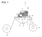
- Fig. 1 is a drawing representing an inkjet printer 1 of the inkjet recording apparatus as an embodiment of the present invention.
- This inkjet printer 1 is a serial head type inkjet printer 1.
- the inkjet printer 1 has a rod-shaped guide rail 2, as shown in Fig. 1 and a carriage 3 is supported by the guide rail 2.
- the carriage 3 performs a reciprocating motion in the main scanning direction X along the guide rail 2 by means of a carriage drive mechanism (not illustrated).
- the carriage 3 is equipped with a recording head 5 having a nozzle (not illustrated) that discharges the ink of each of yellow (Y), magenta (M) cyan (C) and black (K) to a recording medium 4.
- a recording head 5 having a nozzle (not illustrated) that discharges the ink of each of yellow (Y), magenta (M) cyan (C) and black (K) to a recording medium 4.
- the recording medium 4 woven from fabric or plastic material (polyvinyl chloride) because of low rigidity and easy formation of creases. Especially the recording medium 4 impervious to electric charging can be utilized.
- the central portion of the movable range of the carriage 3 is assumed as a recording area for recording on the recording medium 4.
- This recording area contains a conveyance section 6 for conveying the recording medium 4 in the direction Y orthogonal to the widthwise direction.
- an annular conveyance belt 7 for supporting the recording medium 4 on a flat plane and moving it in the horizontal direction is tightened by a drive roller 8 for rotating the conveyance belt 7, and a tension roller 9, driven by the drive roller 8, for applying tension to the conveyance belt 7.
- the conveyance section 6 repeats conveyance and stop of the recording medium 4 in conformity to the operation of the carriage 3 at the time of recording an image so that the recording medium 4 is conveyed intermittently.
- An electrostatic generator 10 is arranged below the recording medium supporting surface for supporting the recording medium 4 on a flat plane, wherein the electrostatic generator 10 generates electrostatic force for sucking the recording medium 4 and supplies electrostatic force to the conveyance belt 7.
- This electrostatic generator 10 has a plurality of thermocouples (not illustrated) where cathodes and anodes are alternately arranged in a comb-toothed form.
- the conveyance belt 7 is electrically changed by applying d.c. voltage to this thermocouple.
- Table 1 shows the relationship between the electrostatic suction force and the presence/absence of the deflection in ink particles discharged to the recording medium 4 from the recording head 5.
- Table 1 has been formed according to the following procedure: A deflection evaluation chart was created by repeatedly recording one-dot lines on a 119 cm-wide sample, leaving a one-dot space. If image irregularities were found by visual observation, the ink particles were considered to be deflected. If no image irregularities were found, the ink particles were evaluated as being free from deflection. A mark "B” is given when there is no deviation of ink particles, and "D" is assigned if there is a deviation.
- Electrostatic suction (N/100 cm 2 (for PET)) 0.5 0.6 0.7 0.8 0.9 1.0 Ink particles deflected or not B B B D D D
- the electrostatic generator 10 applies d.c. voltage to the electrode couple so that the electrostatic suction will not exceed 0.7 N/100 cm 2 .
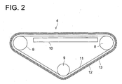
- the conveyance belt 7 has a substrate 11.
- An electrostatic force holding layer 12 capable of holding electrostatic force is provided on the outer surface of this substrate 11.
- the substrate 11 indludes glass cloth, for example.
- the electrostatic force holding layer 12 is preferred to be made of Teflon (polytetrafluoroethylene: registered trademark), for example, to ensure that the conveyance belt 7 holds the electrostatic force to provide satisfactory suction of the recording medium 4.
- an adhesive layer 13 is arranged on the surface of the electrostatic force holding layer 12, where the adhesive layer 13 includes silicone- or urethane-based resin and has a flat surface. This arrangement provides adhesion to the surface of the conveyance belt 7 which is in contact with the recording medium 4.
- Table 2 shows the relationship between the adhesion and looseness of the fabric.
- Table 2 has been created according to the following procedure: A weight roller was rolled on a 140 cm x 50 cm fabric placed on the conveyance belt to apply a surface pressure of 20 g/cm 3 . Then evaluation was made by visual observation to see if the fabric was loosened or not. A mark “B” was given if it was not loosened, and "D” was given if it was loosened. The adhesion is based on the 90-degrees Celsius peeling test conforming to the JIS (the Japanese Industrial Standards) Z0237. Table 2 shows that fabric is not loose if the adhesion is 0.02 N/25 mm or more. Electrostatic suction (N/25 mm 2 (for PET)) 0.03 0.03 0.02 0.02 0.01 0.01 0.005 0.005 0.003 0.003 Fabric loose or not B B D D D D
- the adhesive layer 13 is formed in such a way that the adhesion is 0.02 N/25 mm or more.
- the adhesive layer has a flat surface. Being "flat” in this case refers to such a level of flatness that the recording medium 4 can be prevented from becoming loose, by the irregularities on the surface, and the recording medium and conveyance belt can be kept in close contact with each other, to the extent of allowing polarization of the electric charge of the recording medium.
- Table 3 shows the relationship between adhesion and the possibility of horizontal movement.
- Table 3 has been created according to the following procedure: A weight roller was rolled on a 140 cm x 50 cm fabric placed on the conveyance belt to apply surface pressure of 20 g/cm 2 . One side of 140 cm was moved in the horizontal direction. In this case, measurement was made by visual observation to check whether or not it could be moved without a crease or looseness occurring to the fabric. The result of this measurement was summarized in Table 3. A mark “B” was given when horizontal movement was made without a crease occurring to the fabric, while “D” was given when this movement failed.
- the adhesion is based on the 90-degree Celsius peeling test conforming to the JIS (the Japanese Industrial Standards) Z0237.
- the inkjet printer 1 has a feedout roller 14 for feeding a long-scale recording medium 4 to the conveyance section 6, and a winding roller 15 for winding up the recording medium 4 with an image recorded thereon.
- the feedout roller 14 and winding roller 15 are designed to feed out and wind the recording medium 4, respectively in conformity to the image recording operation by a roller drive mechanism (not illustrated).
- a conveyance roller 16 for conveying the recording medium 4 in the direction of its conveyance Y together with the conveyance belt 7 is located between the feedout roller 14 and winding roller 15, upstream from the recording medium contact surface of the conveyance belt 7.
- the conveyance section 6 and roller drive mechanism are driven, and the recording medium 4 is fed downward of the recording head 5.
- the carriage drive mechanism actuates to cause the carriage 3 to make a reciprocating motion over the recording medium 4. Then a predetermined amount of ink particle is discharged sequentially from the recording head 5 based on the image information, and are hardened after having hit the recording medium 4, whereby an image is recorded.
- the recording medium supporting surface of the conveyance belt 7 On the recording medium supporting surface of the conveyance belt 7, a predetermined d.c. voltage is applied to the electrode couple constituting the electrostatic generator 10, whereby the electrostatic force holding layer 12 is electrostatically charged and electrostatic force is maintained. Further, the adhesive layer 13 of a flat surface having an adhesion of 0.02 N/25 mm or more is formed on the recording medium contact surface. Thus, the recording medium 4 is thoroughly kept in close contact with the conveyance belt 7, with the result that the recording medium 4 is sufficiently sucked by the conveyance belt 7 through polarization of the electric charge of the recording medium 4.
- adhesion does not exceed 1 N/25 mm; therefore, easy correction of the displacement of the recording medium 4 is provided by suspending the generation of electrostatic force, without the need of separating the recording medium 4 kept in close contact with the conveyance belt 7 or bringing it again in contact.
- the electrostatic force does not exceed 0.7 N/25 mm, the ink particle discharged from the recording head 5 to the recording medium 4 does not deflect.
- the adhesive layer 13 of a flat surface having a predetermined adhesion is formed on the recording medium contact surface of the conveyance belt 7.
- the recording medium 4 is thoroughly kept in close contact with the conveyance belt 7, and the recording medium 4 is sufficiently sucked through polarization of the electric discharge of the recording medium 4, with the result that accurate conveyance of the recording medium 4, and hence a satisfactory image are provided.
- the recording medium 4 can be polarized. This arrangement allows the conveyance belt 7 to have a certain thickness, and ensures excellent durability of the conveyance belt 7, reduced frequency in the replacement of the conveyance belt 7 and minimized time and effort in the replacement of the conveyance belt 7.
- the conveyance belt 7 is equipped with the adhesive layer 13 formed of adhesive material on the outer surface.
- the substrate may be impregnated with adhesive material.
Landscapes
- Ink Jet (AREA)
- Handling Of Sheets (AREA)
Applications Claiming Priority (2)
| Application Number | Priority Date | Filing Date | Title |
|---|---|---|---|
| JP2003333207A JP2005096280A (ja) | 2003-09-25 | 2003-09-25 | インクジェット記録装置 |
| JP2003333207 | 2003-09-25 |
Publications (2)
| Publication Number | Publication Date |
|---|---|
| EP1518700A1 true EP1518700A1 (de) | 2005-03-30 |
| EP1518700B1 EP1518700B1 (de) | 2009-03-11 |
Family
ID=34191482
Family Applications (1)
| Application Number | Title | Priority Date | Filing Date |
|---|---|---|---|
| EP04255701A Expired - Lifetime EP1518700B1 (de) | 2003-09-25 | 2004-09-20 | Tintenstrahldrucker |
Country Status (4)
| Country | Link |
|---|---|
| US (1) | US7052126B2 (de) |
| EP (1) | EP1518700B1 (de) |
| JP (1) | JP2005096280A (de) |
| DE (1) | DE602004019859D1 (de) |
Cited By (2)
| Publication number | Priority date | Publication date | Assignee | Title |
|---|---|---|---|---|
| EP1674275A3 (de) * | 2004-12-22 | 2006-09-27 | Konica Minolta Holdings, Inc. | Tintenstrahldrucker, Tintenstrahldruckverfahren und Druckerzeugnis |
| FR2894600A1 (fr) * | 2005-12-13 | 2007-06-15 | Asselin Thibeau Soc Par Action | Transport d'une bande de non-tisse au moyen d'une bande de transport avec portion ascendante et/ou a vitesse variable |
Families Citing this family (9)
| Publication number | Priority date | Publication date | Assignee | Title |
|---|---|---|---|---|
| US7165832B2 (en) * | 2003-09-24 | 2007-01-23 | Fuji Photo Film Co., Ltd. | Image forming apparatus |
| US7419318B2 (en) * | 2004-09-16 | 2008-09-02 | Konica Minolta Medical & Graphic, Inc. | Recording medium conveying device |
| JP4811045B2 (ja) * | 2005-04-25 | 2011-11-09 | コニカミノルタホールディングス株式会社 | インクジェット記録装置 |
| DE102007024945A1 (de) * | 2006-06-06 | 2007-12-13 | Eastman Kodak Co. | Verfahren und Vorrichtung zum Transport eines Bogens in einer Druckmaschine |
| JP4737024B2 (ja) * | 2006-10-04 | 2011-07-27 | ブラザー工業株式会社 | 記録装置用のプラテン及び記録装置 |
| JP4306756B2 (ja) * | 2007-03-29 | 2009-08-05 | ブラザー工業株式会社 | 画像記録装置 |
| JP5678683B2 (ja) * | 2011-01-24 | 2015-03-04 | セイコーエプソン株式会社 | 印刷装置及び印刷方法 |
| JP6119975B2 (ja) * | 2013-03-01 | 2017-04-26 | セイコーエプソン株式会社 | 記録装置及び記録方法 |
| JP6260180B2 (ja) * | 2013-10-02 | 2018-01-17 | セイコーエプソン株式会社 | 記録装置 |
Citations (4)
| Publication number | Priority date | Publication date | Assignee | Title |
|---|---|---|---|---|
| US5225852A (en) * | 1990-04-17 | 1993-07-06 | Canon Kabushiki Kaisha | Recording material transport device and recording apparatus having the same |
| JPH07137877A (ja) | 1993-11-16 | 1995-05-30 | Canon Inc | シート材搬送装置 |
| EP0705707A1 (de) * | 1994-10-07 | 1996-04-10 | Canon Kabushiki Kaisha | Druckgerät |
| JP2001277656A (ja) | 2000-03-30 | 2001-10-09 | Seiren Co Ltd | インクジェットプリント装置 |
Family Cites Families (7)
| Publication number | Priority date | Publication date | Assignee | Title |
|---|---|---|---|---|
| US3448979A (en) * | 1967-05-10 | 1969-06-10 | Schick X Ray Co Inc | Feeding and transporting mechanism for x-ray films or other sheets |
| JPS54140372A (en) * | 1978-04-21 | 1979-10-31 | Taihei Chem | Electrostatic holding conveyor belt and electrostatic holding shifter that use said belt |
| GB8626718D0 (en) * | 1986-11-08 | 1986-12-10 | Andrew Ltd Edward W | Belt |
| JPH06220781A (ja) * | 1993-01-28 | 1994-08-09 | Kanebo Ltd | 捺染方法および装置 |
| US6309064B1 (en) * | 1997-11-20 | 2001-10-30 | Canon Kabushiki Kaisha | Printing apparatus |
| DE19921271A1 (de) * | 1998-06-03 | 1999-12-09 | Heidelberger Druckmasch Ag | Verfahren zum Fördern von Bogen in einer Druckmaschine sowie eine Vorrichtung zur Durchführung des Verfahrens |
| US6652938B1 (en) * | 1998-11-09 | 2003-11-25 | Kaneka Corporation | Media transport belt |
-
2003
- 2003-09-25 JP JP2003333207A patent/JP2005096280A/ja active Pending
-
2004
- 2004-09-15 US US10/942,157 patent/US7052126B2/en not_active Expired - Lifetime
- 2004-09-20 EP EP04255701A patent/EP1518700B1/de not_active Expired - Lifetime
- 2004-09-20 DE DE602004019859T patent/DE602004019859D1/de not_active Expired - Lifetime
Patent Citations (6)
| Publication number | Priority date | Publication date | Assignee | Title |
|---|---|---|---|---|
| US5225852A (en) * | 1990-04-17 | 1993-07-06 | Canon Kabushiki Kaisha | Recording material transport device and recording apparatus having the same |
| JPH07137877A (ja) | 1993-11-16 | 1995-05-30 | Canon Inc | シート材搬送装置 |
| US5531436A (en) * | 1993-11-16 | 1996-07-02 | Canon Kabushiki Kaisha | Sheet transport apparatus with minimized load between electrostatic generating device and transport belt |
| EP0705707A1 (de) * | 1994-10-07 | 1996-04-10 | Canon Kabushiki Kaisha | Druckgerät |
| JP2001277656A (ja) | 2000-03-30 | 2001-10-09 | Seiren Co Ltd | インクジェットプリント装置 |
| US6511152B2 (en) * | 2000-03-30 | 2003-01-28 | Seiren Co., Ltd. | Inkjet printer with cleaning means |
Cited By (3)
| Publication number | Priority date | Publication date | Assignee | Title |
|---|---|---|---|---|
| EP1674275A3 (de) * | 2004-12-22 | 2006-09-27 | Konica Minolta Holdings, Inc. | Tintenstrahldrucker, Tintenstrahldruckverfahren und Druckerzeugnis |
| FR2894600A1 (fr) * | 2005-12-13 | 2007-06-15 | Asselin Thibeau Soc Par Action | Transport d'une bande de non-tisse au moyen d'une bande de transport avec portion ascendante et/ou a vitesse variable |
| EP1798175A1 (de) * | 2005-12-13 | 2007-06-20 | Asselin-Thibeau | Förderung einer Vliesstoffbahn mittels einer Förderbahn mit aufsteigendem Förderteil und/oder veränderlicher Geschwindigkeit |
Also Published As
| Publication number | Publication date |
|---|---|
| DE602004019859D1 (de) | 2009-04-23 |
| EP1518700B1 (de) | 2009-03-11 |
| US7052126B2 (en) | 2006-05-30 |
| US20050068399A1 (en) | 2005-03-31 |
| JP2005096280A (ja) | 2005-04-14 |
Similar Documents
| Publication | Publication Date | Title |
|---|---|---|
| US7052126B2 (en) | Inkjet recording apparatus | |
| US8192011B2 (en) | System and method for discharging static in a printer | |
| JP4563650B2 (ja) | 用紙搬送装置及び画像形成装置 | |
| JPH07137877A (ja) | シート材搬送装置 | |
| US20090058911A1 (en) | Image forming apparatus | |
| JP6318906B2 (ja) | 画像形成装置 | |
| KR102299677B1 (ko) | 잉크-젯 프린팅 시스템 | |
| JP2015218419A (ja) | インクジェット記録装置及び画像形成方法 | |
| CN107264074A (zh) | 印刷装置 | |
| WO2003100152A1 (fr) | Imprimante a jet d'encre pour impression sur textile et procede de production d'impression sur textile | |
| JP2003104580A (ja) | シート搬送装置およびこれを備えた画像形成装置 | |
| JP6098253B2 (ja) | 画像形成装置 | |
| JP5587847B2 (ja) | インクジェット記録装置、浮き上がり検知装置、記録ユニット | |
| JP6476604B2 (ja) | 用紙搬送装置、画像形成装置 | |
| JP2014237549A (ja) | 画像形成装置 | |
| JPH05105260A (ja) | 印写材支持搬送ベルト | |
| JP4076085B2 (ja) | 用紙搬送装置及び画像形成装置 | |
| JP6070000B2 (ja) | 画像形成装置 | |
| JP2004131242A (ja) | 用紙搬送装置及び画像記録装置 | |
| JP2017132043A (ja) | 印刷装置 | |
| JP2021109317A (ja) | インクジェット記録装置、及び袋状基材の製造方法 | |
| JP2016010866A (ja) | 記録装置 | |
| CN107042707A (zh) | 液体喷出装置 | |
| JP4439015B2 (ja) | 用紙搬送装置及び画像形成装置 | |
| JP2019116041A (ja) | 搬送装置及び画像形成装置 |
Legal Events
| Date | Code | Title | Description |
|---|---|---|---|
| PUAI | Public reference made under article 153(3) epc to a published international application that has entered the european phase |
Free format text: ORIGINAL CODE: 0009012 |
|
| AK | Designated contracting states |
Kind code of ref document: A1 Designated state(s): AT BE BG CH CY CZ DE DK EE ES FI FR GB GR HU IE IT LI LU MC NL PL PT RO SE SI SK TR |
|
| AX | Request for extension of the european patent |
Extension state: AL HR LT LV MK |
|
| 17P | Request for examination filed |
Effective date: 20050902 |
|
| AKX | Designation fees paid |
Designated state(s): DE FR GB IT |
|
| GRAP | Despatch of communication of intention to grant a patent |
Free format text: ORIGINAL CODE: EPIDOSNIGR1 |
|
| GRAS | Grant fee paid |
Free format text: ORIGINAL CODE: EPIDOSNIGR3 |
|
| GRAA | (expected) grant |
Free format text: ORIGINAL CODE: 0009210 |
|
| AK | Designated contracting states |
Kind code of ref document: B1 Designated state(s): DE FR GB IT |
|
| REG | Reference to a national code |
Ref country code: GB Ref legal event code: FG4D |
|
| REF | Corresponds to: |
Ref document number: 602004019859 Country of ref document: DE Date of ref document: 20090423 Kind code of ref document: P |
|
| PLBE | No opposition filed within time limit |
Free format text: ORIGINAL CODE: 0009261 |
|
| STAA | Information on the status of an ep patent application or granted ep patent |
Free format text: STATUS: NO OPPOSITION FILED WITHIN TIME LIMIT |
|
| 26N | No opposition filed |
Effective date: 20091214 |
|
| REG | Reference to a national code |
Ref country code: FR Ref legal event code: ST Effective date: 20100531 |
|
| PG25 | Lapsed in a contracting state [announced via postgrant information from national office to epo] |
Ref country code: FR Free format text: LAPSE BECAUSE OF NON-PAYMENT OF DUE FEES Effective date: 20090930 |
|
| PG25 | Lapsed in a contracting state [announced via postgrant information from national office to epo] |
Ref country code: IT Free format text: LAPSE BECAUSE OF FAILURE TO SUBMIT A TRANSLATION OF THE DESCRIPTION OR TO PAY THE FEE WITHIN THE PRESCRIBED TIME-LIMIT Effective date: 20090311 |
|
| PGFP | Annual fee paid to national office [announced via postgrant information from national office to epo] |
Ref country code: DE Payment date: 20130918 Year of fee payment: 10 |
|
| PGFP | Annual fee paid to national office [announced via postgrant information from national office to epo] |
Ref country code: GB Payment date: 20130918 Year of fee payment: 10 |
|
| REG | Reference to a national code |
Ref country code: DE Ref legal event code: R119 Ref document number: 602004019859 Country of ref document: DE |
|
| GBPC | Gb: european patent ceased through non-payment of renewal fee |
Effective date: 20140920 |
|
| REG | Reference to a national code |
Ref country code: DE Ref legal event code: R119 Ref document number: 602004019859 Country of ref document: DE Effective date: 20150401 |
|
| PG25 | Lapsed in a contracting state [announced via postgrant information from national office to epo] |
Ref country code: GB Free format text: LAPSE BECAUSE OF NON-PAYMENT OF DUE FEES Effective date: 20140920 Ref country code: DE Free format text: LAPSE BECAUSE OF NON-PAYMENT OF DUE FEES Effective date: 20150401 |