EP1518047B1 - Verfahren zur bestimmung einer beladung eines aktivkohlebehälters eines tankentlüftungssystems - Google Patents
Verfahren zur bestimmung einer beladung eines aktivkohlebehälters eines tankentlüftungssystems Download PDFInfo
- Publication number
- EP1518047B1 EP1518047B1 EP03735358A EP03735358A EP1518047B1 EP 1518047 B1 EP1518047 B1 EP 1518047B1 EP 03735358 A EP03735358 A EP 03735358A EP 03735358 A EP03735358 A EP 03735358A EP 1518047 B1 EP1518047 B1 EP 1518047B1
- Authority
- EP
- European Patent Office
- Prior art keywords
- exhaust
- tank ventilation
- activated carbon
- engine
- gas temperature
- Prior art date
- Legal status (The legal status is an assumption and is not a legal conclusion. Google has not performed a legal analysis and makes no representation as to the accuracy of the status listed.)
- Expired - Lifetime
Links
- OKTJSMMVPCPJKN-UHFFFAOYSA-N Carbon Chemical compound [C] OKTJSMMVPCPJKN-UHFFFAOYSA-N 0.000 title claims description 114
- 238000009423 ventilation Methods 0.000 title claims description 51
- 238000000034 method Methods 0.000 title claims description 33
- 238000011068 loading method Methods 0.000 claims description 28
- 230000008929 regeneration Effects 0.000 claims description 27
- 238000011069 regeneration method Methods 0.000 claims description 27
- 238000002347 injection Methods 0.000 claims description 24
- 239000007924 injection Substances 0.000 claims description 24
- 238000011144 upstream manufacturing Methods 0.000 claims description 10
- 230000003197 catalytic effect Effects 0.000 claims description 9
- 230000001419 dependent effect Effects 0.000 claims description 8
- 238000010586 diagram Methods 0.000 claims description 6
- 239000007789 gas Substances 0.000 description 43
- 239000003054 catalyst Substances 0.000 description 31
- 239000000446 fuel Substances 0.000 description 30
- 238000002485 combustion reaction Methods 0.000 description 20
- 229930195733 hydrocarbon Natural products 0.000 description 19
- 150000002430 hydrocarbons Chemical class 0.000 description 19
- 239000000203 mixture Substances 0.000 description 13
- 239000000523 sample Substances 0.000 description 6
- 238000006243 chemical reaction Methods 0.000 description 5
- 230000000875 corresponding effect Effects 0.000 description 5
- 238000013022 venting Methods 0.000 description 5
- 230000006978 adaptation Effects 0.000 description 3
- 230000015572 biosynthetic process Effects 0.000 description 3
- 238000005259 measurement Methods 0.000 description 3
- CURLTUGMZLYLDI-UHFFFAOYSA-N Carbon dioxide Chemical compound O=C=O CURLTUGMZLYLDI-UHFFFAOYSA-N 0.000 description 2
- QVGXLLKOCUKJST-UHFFFAOYSA-N atomic oxygen Chemical compound [O] QVGXLLKOCUKJST-UHFFFAOYSA-N 0.000 description 2
- 239000003610 charcoal Substances 0.000 description 2
- 230000006835 compression Effects 0.000 description 2
- 238000007906 compression Methods 0.000 description 2
- 238000011010 flushing procedure Methods 0.000 description 2
- 239000000463 material Substances 0.000 description 2
- 229910052760 oxygen Inorganic materials 0.000 description 2
- 239000001301 oxygen Substances 0.000 description 2
- 238000010926 purge Methods 0.000 description 2
- 230000004913 activation Effects 0.000 description 1
- 230000033228 biological regulation Effects 0.000 description 1
- 238000004364 calculation method Methods 0.000 description 1
- 229910002092 carbon dioxide Inorganic materials 0.000 description 1
- 239000001569 carbon dioxide Substances 0.000 description 1
- 238000012937 correction Methods 0.000 description 1
- 230000002596 correlated effect Effects 0.000 description 1
- 230000007423 decrease Effects 0.000 description 1
- 238000001514 detection method Methods 0.000 description 1
- 230000000694 effects Effects 0.000 description 1
- 230000008020 evaporation Effects 0.000 description 1
- 238000001704 evaporation Methods 0.000 description 1
- 238000001914 filtration Methods 0.000 description 1
- 238000010304 firing Methods 0.000 description 1
- 230000005283 ground state Effects 0.000 description 1
- 230000000977 initiatory effect Effects 0.000 description 1
- 238000012544 monitoring process Methods 0.000 description 1
- 230000001172 regenerating effect Effects 0.000 description 1
- 239000007787 solid Substances 0.000 description 1
- 239000000243 solution Substances 0.000 description 1
- 230000029305 taxis Effects 0.000 description 1
- 238000012360 testing method Methods 0.000 description 1
- 230000008016 vaporization Effects 0.000 description 1
- XLYOFNOQVPJJNP-UHFFFAOYSA-N water Substances O XLYOFNOQVPJJNP-UHFFFAOYSA-N 0.000 description 1
Images


Classifications
-
- F—MECHANICAL ENGINEERING; LIGHTING; HEATING; WEAPONS; BLASTING
- F02—COMBUSTION ENGINES; HOT-GAS OR COMBUSTION-PRODUCT ENGINE PLANTS
- F02M—SUPPLYING COMBUSTION ENGINES IN GENERAL WITH COMBUSTIBLE MIXTURES OR CONSTITUENTS THEREOF
- F02M25/00—Engine-pertinent apparatus for adding non-fuel substances or small quantities of secondary fuel to combustion-air, main fuel or fuel-air mixture
- F02M25/08—Engine-pertinent apparatus for adding non-fuel substances or small quantities of secondary fuel to combustion-air, main fuel or fuel-air mixture adding fuel vapours drawn from engine fuel reservoir
-
- F—MECHANICAL ENGINEERING; LIGHTING; HEATING; WEAPONS; BLASTING
- F02—COMBUSTION ENGINES; HOT-GAS OR COMBUSTION-PRODUCT ENGINE PLANTS
- F02D—CONTROLLING COMBUSTION ENGINES
- F02D41/00—Electrical control of supply of combustible mixture or its constituents
- F02D41/0025—Controlling engines characterised by use of non-liquid fuels, pluralities of fuels, or non-fuel substances added to the combustible mixtures
- F02D41/003—Adding fuel vapours, e.g. drawn from engine fuel reservoir
- F02D41/0045—Estimating, calculating or determining the purging rate, amount, flow or concentration
-
- F—MECHANICAL ENGINEERING; LIGHTING; HEATING; WEAPONS; BLASTING
- F02—COMBUSTION ENGINES; HOT-GAS OR COMBUSTION-PRODUCT ENGINE PLANTS
- F02D—CONTROLLING COMBUSTION ENGINES
- F02D41/00—Electrical control of supply of combustible mixture or its constituents
- F02D41/02—Circuit arrangements for generating control signals
- F02D41/14—Introducing closed-loop corrections
- F02D41/1438—Introducing closed-loop corrections using means for determining characteristics of the combustion gases; Sensors therefor
- F02D41/1444—Introducing closed-loop corrections using means for determining characteristics of the combustion gases; Sensors therefor characterised by the characteristics of the combustion gases
- F02D41/1446—Introducing closed-loop corrections using means for determining characteristics of the combustion gases; Sensors therefor characterised by the characteristics of the combustion gases the characteristics being exhaust temperatures
-
- F—MECHANICAL ENGINEERING; LIGHTING; HEATING; WEAPONS; BLASTING
- F02—COMBUSTION ENGINES; HOT-GAS OR COMBUSTION-PRODUCT ENGINE PLANTS
- F02D—CONTROLLING COMBUSTION ENGINES
- F02D41/00—Electrical control of supply of combustible mixture or its constituents
- F02D41/02—Circuit arrangements for generating control signals
- F02D41/14—Introducing closed-loop corrections
- F02D41/1401—Introducing closed-loop corrections characterised by the control or regulation method
- F02D2041/1433—Introducing closed-loop corrections characterised by the control or regulation method using a model or simulation of the system
-
- F—MECHANICAL ENGINEERING; LIGHTING; HEATING; WEAPONS; BLASTING
- F02—COMBUSTION ENGINES; HOT-GAS OR COMBUSTION-PRODUCT ENGINE PLANTS
- F02D—CONTROLLING COMBUSTION ENGINES
- F02D41/00—Electrical control of supply of combustible mixture or its constituents
- F02D41/0025—Controlling engines characterised by use of non-liquid fuels, pluralities of fuels, or non-fuel substances added to the combustible mixtures
- F02D41/003—Adding fuel vapours, e.g. drawn from engine fuel reservoir
- F02D41/0042—Controlling the combustible mixture as a function of the canister purging, e.g. control of injected fuel to compensate for deviation of air fuel ratio when purging
-
- F—MECHANICAL ENGINEERING; LIGHTING; HEATING; WEAPONS; BLASTING
- F02—COMBUSTION ENGINES; HOT-GAS OR COMBUSTION-PRODUCT ENGINE PLANTS
- F02D—CONTROLLING COMBUSTION ENGINES
- F02D41/00—Electrical control of supply of combustible mixture or its constituents
- F02D41/30—Controlling fuel injection
- F02D41/3011—Controlling fuel injection according to or using specific or several modes of combustion
- F02D41/3017—Controlling fuel injection according to or using specific or several modes of combustion characterised by the mode(s) being used
- F02D41/3023—Controlling fuel injection according to or using specific or several modes of combustion characterised by the mode(s) being used a mode being the stratified charge spark-ignited mode
Definitions
- the invention relates to a method for determining a load an activated carbon container of a tank ventilation system according to the preamble of patent claim 1 and a direct injection Otto engine according to the preamble of the claim 9th
- Direct injection gasoline engines have injectors or injectors that inject the fuel directly into the cylinder inject the engine.
- Fuel in cylinders become operating modes of the engine. Is the injection during the suction of the air, so that the injected Fuel has enough time in the entire combustion chamber to distribute uniformly, one speaks of a homogeneous one Operation of the gasoline engine.
- the homogeneous operation distinguishes essentially not from previously known combustion processes with injection of the fuel into the intake channel. in the Ideal case of homogeneous operation burns the fuel Completely.
- an engine control unit controls a regeneration valve (RV).
- the flow rate can be in the work area of the regeneration valve almost continuously over a map adjustment with the parameters load and speed Taxes. In certain operating areas the regeneration switches off (idle) or can not work (for example at full load, i. lack of negative pressure, or a shift operation without throttling).
- a lambda control monitors whether at power up regeneration the added amount of fuel the given Adheres to limits. If the flow is too large, the Flow rate decreases to driveability and exhaust emissions to keep in an optimal range.
- a loading of the activated carbon container determined.
- Appropriate condition for such a relationship is a substantially complete combustion of all hydrocarbons.
- the motor In shift operation, the motor must be slightly throttled, thus over a resulting negative pressure of the activated carbon container can be regenerated.
- the hydrocarbons from the activated carbon container get distributed homogeneously in the Combustion chamber and there are only partially burned.
- the unburned Hydrocarbons enter the catalyst chemically reacted there and increase the catalyst temperature.
- DE 199 47 080 C1 discloses a device and a method for the regeneration of an activated carbon filter known. there is used to regenerate an activated carbon container, which in the Tank ventilation of an internal combustion engine, which with air-assisted Gasoline direct injection is provided is, on the high pressure side of the compressed air for the Injection generating pressure unit a pressure regulator connected, whose drained air through the activated carbon container is passed to regenerate this.
- From DE 196 17 386 C1 is a tank ventilation system for a directly injecting internal combustion engine known.
- the internal combustion engine has an air-assisted injection system on, wherein in certain operating conditions of the internal combustion engine the purge air for regenerating the activated carbon filter the tank ventilation system by means of an air compressor generated atomizing air for the injection system is added.
- the object of the present invention is the specification of methods with which a simple determination of a loading condition an activated carbon container is possible. This task is achieved by a method having the features of the claim 1 and a gasoline engine with the features of the claim 9th
- the loading state is an activated carbon container in a simple manner ascertainable, so that, for example, on the basis of this Loading state one taking into account a desired Force-air ratio optimal tank ventilation can be carried out.
- a first preferred embodiment of the inventive Procedure becomes a downstream of the gasoline engine Downstream catalyst detected exhaust gas temperature when operating the tank ventilation with one switched off or inactive tank ventilation determined exhaust gas temperature compared.
- temperatures upstream and downstream of the Catalyst with inactive or active tank ventilation determine, i. to calculate or measure on the Basis of such determined temperatures for the respective Engine operating conditions determine exhaust gas temperature differences, and with appropriate correlation of these temperature differences with active and inactive tank ventilation on to close the loading condition of the activated carbon container.
- control of the regeneration valve is conveniently carried out depending on the exhaust gas temperature, a Speed load operating point of the motor, a loading of the Activated carbon container and / or the operating mode of the engine (homogeneous operation or shift operation) or a combination this parameter.
- Inventive direct injection gasoline engines exhibit expediently downstream and / or upstream of one the gasoline engine downstream catalytic converter thermocouples for measuring the respective exhaust gas temperatures.
- Thermocouples are exhaust gas temperatures in a simpler way and reliably measurable, so that the illustrated Procedures are reliably carried out.
- the inventive gasoline engine with a computer device, for example an engine control unit designed to carry out the inventive method.
- the inventive method allows over conventional Solutions higher regeneration rates, since according to the invention For example, a regeneration in shift operation possible is.
- the engine operation can be a whole larger Share in shift operation, since both in homogeneous operation, as well as in the shift operation can be regenerated. Overall, this results in lower fuel consumption.
- the possibility of regeneration in all engine operating modes also leads to lower unburned emissions Hydrocarbons.
- a spark plug for igniting the air-fuel mixture is denoted by 16.
- FIG. 2 schematically shows an internal combustion engine 21, which has an intake tract 22 for sucking in air.
- In the intake tract 22 is a throttle valve 28 and upstream of this an air mass meter 30, in the over a Intake port 32 intake air is passed.
- the injection rail 26 is connected via a fuel line 27, which is fed from a pump module 37, with fuel provided.
- the pump module 37 is arranged in a tank 40.
- tank 40 In the tank 40 is fuel 41.
- the above the Fuel 41 befindliches cavity is filled with fuel vapor 42nd filled.
- the tank 40 is also via a tank vent line 44, which opens into a ventilation port 46, to the Environment coupled, so that a pressure equalization take place can.
- an activated carbon container 50 connected, which with hydrocarbons absorbing Activated carbon material is formed.
- the Actuator 54 is via unspecified lines of an engine control unit 60 can be controlled.
- the activated carbon container 50 is connected to a second output via a Regenerier réelle 62 with the intake manifold 22 of the internal combustion engine 21 connected.
- the regeneration line 62 opens here between the throttle 28 and the internal combustion engine 21 in the intake 22nd
- a regeneration valve 64 is connected, which is actuated via an actuator 66.
- the regeneration valve 64 is commonly called a tank vent valve designated.
- the controller 60 is unspecified, and only partially shown lines with the air mass meter 30, the throttle valve 28, the injectors 25 and the actuator 66 of the regeneration valve 64 connected and reads about These lines corresponding measured values or controls the corresponding components.
- the charcoal canister 50 absorbs at its the tank 40th facing inlet fuel vapor. To prevent, that with complete loading of the activated carbon container a breakthrough of hydrocarbons to the ventilation port 46 takes place, the activated carbon container 50 is in operation regenerated the internal combustion engine. For this purpose will by switching the regeneration valve 64, the regeneration line 62 activated by the activated carbon container 50 to the intake tract 22. At the same time, the drain valve 52 is closed, so that of this associated output of the activated carbon container 50 is separated from the ventilation port 46. It is then possible, via a (not shown) line the activated carbon container 50 air to be supplied, which then with open Regenerierventil 64 through the regeneration line 62 under Entrainment of fuel vapors from the activated carbon container 50 flows into the exhaust tract 22.
- the mixture composition is in homogeneous operation of the engine changed by about 20%.
- the flow rate can be located in the working area of the regeneration valve almost continuously via a map adaptation with the parameters Control load and speed. In certain operating areas switches off regeneration (eg idle), or can not work.
- the catalyst 70 downstream Thermocouple 74 is provided, by means of which the temperature of the exhaust gas downstream of the catalyst are measured can. Based on the difference in the exhaust gas temperature at carried out tank venting to the exhaust gas temperature without Tank venting may affect the loading condition of the activated carbon canister 50 are closed.
- the realization of the detection of the loading of the activated carbon container 50 can be done in several ways. First With reference to FIG. 3, the possibility of a comparison of a Calculated exhaust gas temperature without tank ventilation with a measured exhaust gas temperature (with effective tank ventilation).
- step 301 When comparing calculated exhaust gas temperature (without tank venting) and measured exhaust gas temperature (with tank ventilation) is first in step 301 from a about engine speed and engine load clamped map the agglomerate temperature determined without corrections. About two more Characteristics are the influences of fuel-air ratio (Lambda) and ignition timing as factors in the exhaust gas temperature included. The creation of the characteristic for the Exhaust gas temperature over lambda is based on the air-fuel ratio in a step 302 and the characteristic for the exhaust gas temperature over a firing angle on the Basis of the ignition timing in a step 303 performed.
- Step 305 For changes in speed, load, ignition timing or lambda These affect only with a certain time delay the exhaust gas temperature downstream of the catalyst, since the Gas column first, the internal combustion engine 21, and then must pass through the catalyst 70.
- the step 305 expediently a delay by means of a delay element is connected upstream in a step 304.
- the thus obtained (calculated) value for the exhaust gas temperature without tank ventilation is in step 306 by the in the exhaust line downstream of the catalyst 70 by means of Temperature member 74 determined (measured) temperature divided. Be unburned HC portions of the tank ventilation in Shift mode implemented in the catalyst, it comes to a (measurable) temperature increase in the exhaust gas, which causes a Factor of the temperature quotient of> 1 results. This temperature quotient serves as input of a characteristic, in the conversion into the current load of the activated carbon container takes place (step 307).
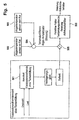
- the tank vent is activated. After connection or activation of the tank ventilation are stored Values of the exhaust gas temperature in the map no longer changed (symbolized by a second, with a solid one Line shown position of the switch 402 ').
- step 404 The values thus determined are, in analogy to step 306, in a step 403 by means of the thermocouple 74th divided temperature measured downstream of the catalyst.
- the loading of the activated carbon container is then analogous to the in the method shown in Figure 3 with the exhaust gas temperature model about quotient formation and conversion by means of a Characteristic determined (step 404).
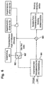
- Step 501 is a speed and load dependent map of a Catalyst exotherm with tank ventilation not switched on calculated.
- steps 502 and 503 the exhaust gas temperatures become measured before and after the catalyst.
- Step 504 becomes the difference from the temperatures thus measured determined.
- the turn by means of delay element and Low-pass modified values of the detected in step 501 Map is in step 505 with the in step 504 detected temperature difference under quotient formation correlated. From the resulting characteristic of the temperature quotient can be the load of the activated carbon container 50 (step 506).
- Step 601 initially with tank ventilation not switched on via suitable speed and load ranges exhaust gas temperatures measured before and after the catalyst (switch 602 'at 602 in dashed line position). The thus determined Temperature differences are in a speed and load-dependent Adaptation map for a catalyst exotherm without Tank ventilation stored.
- Step 603 After switching on the tank ventilation at (602, switch 602 'in the second, by means of a solid Line shown position) are determined so Values by the respectively measured temperature differences divided before and after the catalyst with active tank ventilation (Step 603). On the basis of this quotient formation In step 604, the characteristic of that determined in step 603 is determined Quotient with respect to the loading of the activated carbon container 50 determined. So this algorithm is in turn the catalyst exotherm without tank ventilation by measurement firm with them after the end of the learning phase the measured catalyst exothermic with switched on Tank ventilation compare, and based on this Compare to determine the loading of the activated carbon container.
- a Regulation of the tank ventilation rate expediently to provide a constant exhaust gas temperature or a predetermined Flow rate of the regeneration valve 64.
- Target of Regeneration is here, the bound hydrocarbons to remove from the activated carbon container 50.
- Dependent from a detected charge of the activated carbon canister 50 then carried out a more or less intense regeneration become.
Landscapes
- Engineering & Computer Science (AREA)
- Chemical & Material Sciences (AREA)
- Combustion & Propulsion (AREA)
- Mechanical Engineering (AREA)
- General Engineering & Computer Science (AREA)
- Exhaust Gas After Treatment (AREA)
- Supplying Secondary Fuel Or The Like To Fuel, Air Or Fuel-Air Mixtures (AREA)
- Electrical Control Of Air Or Fuel Supplied To Internal-Combustion Engine (AREA)
Description
- Fig. 1
- eine schematische Darstellung der Einspritzkomponenten eines direkt einspritzenden Ottomotors,
- Fig. 2
- eine schematische Darstellung der wesentlichen Komponenten eines direkteinspritzenden Ottomotors,
- Fig. 3
- ein Schaubild zur Darstellung einer ersten bevorzugten Ausführungsform des erfindungsgemässen Verfahrens,
- Fig. 4
- ein Schaubild zur Darstellung einer zweiten bevorzugten Ausführungsform des erfindungsgemässen Verfahrens,
- Fig. 5
- ein Schaubild zur Darstellung einer dritten bevorzugten Ausführungsform des erfindungsgemässen Verfahrens, und
- Fig. 6
- ein Schaubild zur Darstellung einer vierten bevorzugten Ausführungsform des erfindungsgemässen Verfahrens.
Claims (6)
- Verfahren zur Bestimmung der Beladung eines Aktivkohlebehälters eines Tankentlüftungssystems eines insbesondere direkteinspritzenden Ottomotors, mit einer Feststellung des thermischen Einflusses eines Betriebes der Tankentlüftung auf das Abgas des Ottomotors und einer Feststellung der Beladung des Aktivkohlebehälters auf der Grundlage dieses thermischen Einflusses, wobei eine stromabwärts eines dem Ottomotor nachgeschalteten Katalysators festgestellte Abgastemperatur bei aktiver Tankentlüftung mit einer bei ausgeschalteter bzw. inaktiver Tankentlüftung ermittelten Abgastemperatur verglichen wird,
dadurch gekennzeichnet, dass die Abgastemperaturen bei nicht aktiver Tankentlüftung über ein Modell berechnet werden und durch bei aktivierter Tankentlüftung gemessene Abgastemperaturen geteilt werden, wobei auf der Grundlage derart festgestellter Temperaturquotienten die Beladung des Aktivkohlebehälters berechnet bzw. anhand entsprechender Kennlinienfelder abgeleitet wird oder dass Abgastemperaturen bei nicht aktiver Tankentlüftung gemessen und in einem von der Motordrehzahl und Motorlast abhängigen Kennfeld gespeichert werden, bei aktiver Tankentlüftung gemessene Abgastemperaturen durch die derart gespeicherten Abgastemperaturen dividiert, und die Beladung des Aktivkohlebehälters auf der Grundlage derart ermittelter Temperaturquotienten ermittelt wird. - Verfahren nach Anspruch 1,
dadurch gekennzeichnet, dass Differenzen von Abgastemperaturen vor und nach dem Katalysator bei nicht aktiver Tankentlüftung über ein Modell berechnet werden und durch bei aktivierter Tankentlüftung gemessene Abgastemperaturdifferenzen geteilt werden, wobei auf der Grundlage derart festgestellter Abgastemperaturdifferenzquotienten die Beladung des Aktivkohlebehälters berechnet bzw. anhand entsprechender Kennlinienfelder abgeleitet wird. - Verfahren nach einem der Ansprüche 1 oder 2,
dadurch gekennzeichnet, dass auf der Grundlage vor und nach dem Katalysator gemessener Abgastemperaturen Abgastemperaturdiffereinzen bei nicht aktiver Tankentlüftung gemessen und in einem von der Motordrehzahl und Motorlast abhängigen Kennfeld gespeichert werden, bei aktiver Tankentlüftung gemessene Abgastemperaturdifferenzen durch die derart gespeicherten Abgastemperaturdifferenzen dividiert, und die Beladung des Aktivkohlebehälters auf der Grundlage derart ermittelter Temperaturdifferenzquotienten ermittelt wird. - Verfahren nach einem der vorstehenden Ansprüche,
dadurch gekennzeichnet, dass in Abhängigkeit von einem festgestellten Beladungszustand eines Aktivkohlebehälters eine Steuerung eines Regenerierventils eines mit einem Tankentlüftungssystem ausgebildeten, insbesondere direkt einspritzenden Ottomotors, ausgeführt wird. - Verfahren nach Anspruch 4,
dadurch gekennzeichnet, dass die Steuerung des Regenerierventils in Abhängigkeit von der Abgastemperatur, einem Drehzahl-Last-Betriebspunkt des Motors, einer Beladung des Aktivkohlebehälters, und/oder des Betriebsmodus des Motors oder einer Kombination dieser Parameter durchgeführt wird. - Direkteinspritzender Ottomotor mit einem nachgeschalteten Katalysator (70), mit einem dem Katalysator nachgeschalteten Thermoelement (74) zur Messung der Abgastemperatur stromabwärtig des Katalysators (70) und einem stromaufwärtig des Katalysators (70) ausgebildeten Thermoelement (84) zur Messung einer Abgastemperatur stromaufwärtig des Katalysators (70), gekennzeichnet durch eine das Verfahren nach einem der Ansprüche 1 bis 5 durchführende Rechnereinrichtung (60).
Applications Claiming Priority (3)
| Application Number | Priority Date | Filing Date | Title |
|---|---|---|---|
| DE10228004 | 2002-06-22 | ||
| DE10228004A DE10228004A1 (de) | 2002-06-22 | 2002-06-22 | Verfahren zur Bestimmung einer Beladung eines Aktivkohlebehälters eines Tankentlüftungssystems |
| PCT/EP2003/004651 WO2004001211A1 (de) | 2002-06-22 | 2003-05-03 | Verfahren zur bestimmung einer beladung eines aktivkohlebehälters eines tankentlüftungssystems |
Publications (2)
| Publication Number | Publication Date |
|---|---|
| EP1518047A1 EP1518047A1 (de) | 2005-03-30 |
| EP1518047B1 true EP1518047B1 (de) | 2005-11-30 |
Family
ID=29723388
Family Applications (1)
| Application Number | Title | Priority Date | Filing Date |
|---|---|---|---|
| EP03735358A Expired - Lifetime EP1518047B1 (de) | 2002-06-22 | 2003-05-03 | Verfahren zur bestimmung einer beladung eines aktivkohlebehälters eines tankentlüftungssystems |
Country Status (4)
| Country | Link |
|---|---|
| US (1) | US7013215B2 (de) |
| EP (1) | EP1518047B1 (de) |
| DE (2) | DE10228004A1 (de) |
| WO (1) | WO2004001211A1 (de) |
Families Citing this family (5)
| Publication number | Priority date | Publication date | Assignee | Title |
|---|---|---|---|---|
| US7444233B2 (en) * | 2005-12-27 | 2008-10-28 | Nissan Motor Co., Ltd. | Diagnostic apparatus and diagnostic method for an internal combustion engine |
| EP1956219B1 (de) * | 2007-02-08 | 2008-12-31 | Delphi Technologies, Inc. | Kraftstoffdampf-Tankentlüftungssystem für einen Fahrzeugkraftstofftank |
| KR100999609B1 (ko) * | 2007-09-06 | 2010-12-08 | 현대자동차주식회사 | 캐니스터의 초기 탄화수소 농도 측정방법, 이를 이용한 연료 분사량 제어 방법 및 그 시스템 |
| DE102014221704A1 (de) * | 2014-10-24 | 2016-04-28 | Robert Bosch Gmbh | Tankentlüftungssystem und Verfahren zu seinem Betrieb |
| DE102014115888A1 (de) * | 2014-10-31 | 2016-05-04 | Dr. Ing. H.C. F. Porsche Aktiengesellschaft | Adsorptionseinheit für die Adsorption von Treibstoffdämpfen in einer Tankentlüftung |
Family Cites Families (10)
| Publication number | Priority date | Publication date | Assignee | Title |
|---|---|---|---|---|
| DE4408647B4 (de) * | 1993-03-19 | 2004-02-05 | Volkswagen Ag | Verfahren und Vorrichtung zur Bestimmung der Arbeitskapazität einer Adsorberanordnung |
| DE19701353C1 (de) * | 1997-01-16 | 1998-03-12 | Siemens Ag | Verfahren zur Tankentlüftung bei einer Brennkraftmaschine |
| JP3799758B2 (ja) * | 1997-08-05 | 2006-07-19 | トヨタ自動車株式会社 | 内燃機関の触媒再生装置 |
| DE10019007A1 (de) * | 1999-04-20 | 2000-11-16 | Siemens Ag | Verfahren und Vorrichtung zur Emissionsminderung bei Motoren |
| DE19936202A1 (de) * | 1999-07-31 | 2001-02-08 | Bosch Gmbh Robert | Verfahren zum Betreiben einer Brennkraftmaschine |
| US6233924B1 (en) * | 1999-08-02 | 2001-05-22 | Ford Global Technologies, Inc. | Temperature control method for a direct injection engine |
| DE19947097C1 (de) * | 1999-09-30 | 2001-01-25 | Siemens Ag | Verfahren zur Regenerierung eines Aktivkohlebehälters |
| US6561166B2 (en) * | 2000-06-13 | 2003-05-13 | Visteon Global Technologies, Inc. | Purge fuel canister measurement method and system |
| DE10043699A1 (de) * | 2000-09-04 | 2002-03-14 | Bosch Gmbh Robert | Verfahren zur Bestimmung des Kraftstoffgehaltes des Regeneriergases bei einem Verbrennungsmotor mit Benzindirekteinspritzung im Schichtbetrieb |
| US6568179B2 (en) * | 2001-03-01 | 2003-05-27 | Engelhard Corporation | Apparatus and method for vehicle emissions control |
-
2002
- 2002-06-22 DE DE10228004A patent/DE10228004A1/de not_active Withdrawn
-
2003
- 2003-05-03 WO PCT/EP2003/004651 patent/WO2004001211A1/de not_active Ceased
- 2003-05-03 EP EP03735358A patent/EP1518047B1/de not_active Expired - Lifetime
- 2003-05-03 DE DE50301817T patent/DE50301817D1/de not_active Expired - Lifetime
-
2004
- 2004-12-21 US US11/018,420 patent/US7013215B2/en not_active Expired - Fee Related
Also Published As
| Publication number | Publication date |
|---|---|
| US20050154525A1 (en) | 2005-07-14 |
| EP1518047A1 (de) | 2005-03-30 |
| DE50301817D1 (de) | 2006-01-05 |
| DE10228004A1 (de) | 2004-01-15 |
| US7013215B2 (en) | 2006-03-14 |
| WO2004001211A1 (de) | 2003-12-31 |
Similar Documents
| Publication | Publication Date | Title |
|---|---|---|
| DE19711477C2 (de) | Verfahren und Vorrichtung zum Steuern von Verbrennungsmotoren | |
| DE60314360T2 (de) | Emissionssteuerungssystem zur Erhöhung der Leistungfähigkeit einer selektiven katalytischen Reduktion | |
| DE102018117913A1 (de) | Verfahren und System zur Partikelfilterregeneration | |
| DE19650517C2 (de) | Verfahren und Vorrichtung zur Tankentlüftung für eine direkteinspritzende Brennkraftmaschine | |
| DE102010046896A1 (de) | System und Verfahren zum Regenerieren eines von einem Katalysator begleiteten Partikelfilters | |
| DE10020341C2 (de) | Luft/Kraftstoffverhältnis-Steuer/Regelsystem für einen Verbrennungsmotor | |
| DE102010046895A1 (de) | Kraftstoffsteuerung für fremdgezündeten Motor mit einem Partikelfiltersystem | |
| DE102010046762A1 (de) | System und Verfahren zum Regenerieren eines Partikelfilters | |
| DE102010030640A1 (de) | Späte Nacheinspritzung von Kraftstoff für Partikelfilteraufheizung | |
| DE19755348A1 (de) | Abgastemperatur-Anstiegssystem für einen Zylinder-Inneneinspritzungs-Innenverbrennungsmotor | |
| DE102006043670A1 (de) | System und Verfahren für einen aufgeladenen Motor mit Direkteinspritzung | |
| DE102010032545A1 (de) | Verfahren zum Detektieren und Mindern von ungebetenen exothermen Vorgängen in einem Dieselnachbehandlungssystem | |
| DE102007045817A1 (de) | Verfahren und Vorrichtung zum Steuern des Motorbetriebs während der Regeneration eines Abgasnachbehandlungssystems | |
| DE60122642T2 (de) | Steuerungsvorrichtung für das Kraftstoff-Luft-Verhältnis in einer Brennkraftmaschine | |
| DE102006020675A1 (de) | Verfahren zur Lambda- und Momentenregelung einer Verbrennungskraftmaschine sowie Programmalgorithmus | |
| DE10026359B4 (de) | Abgasreinigungsanlage für eine fremdgezündete, aufgeladene Verbrennungskraftmaschine und Verfahren zum Betrieb derselben | |
| DE102010000289A1 (de) | Abgas-Emissions-Steuerungssystem | |
| EP1518047B1 (de) | Verfahren zur bestimmung einer beladung eines aktivkohlebehälters eines tankentlüftungssystems | |
| DE60018665T2 (de) | Ein Steuersystem für einen direkt eingespritzten, fremdgezündeten Motor | |
| DE102006022321A1 (de) | System und Verfahren zum Reduzieren von NOx-Emissionen bei einer einen Dieselmotor aufweisenden Vorrichtung | |
| DE60123144T2 (de) | Regeleinrichtung für eine Brennkraftmaschine | |
| DE102004024864B4 (de) | Steuervorrichtung für einen Verbrennungsmotor und Verbrennungsmotor | |
| DE19913407A1 (de) | Verfahren zum Betreiben einer Brennkraftmaschine | |
| DE69919473T2 (de) | Brennkraftmaschine | |
| WO2017093061A1 (de) | Verfahren und vorrichtung zum betrieb einer brennkraftmaschine, insbesondere eines kraftfahrzeugs mit dualer kraftstoffeinspritzung |
Legal Events
| Date | Code | Title | Description |
|---|---|---|---|
| PUAI | Public reference made under article 153(3) epc to a published international application that has entered the european phase |
Free format text: ORIGINAL CODE: 0009012 |
|
| 17P | Request for examination filed |
Effective date: 20041204 |
|
| AK | Designated contracting states |
Kind code of ref document: A1 Designated state(s): AT BE BG CH CY CZ DE DK EE ES FI FR GB GR HU IE IT LI LU MC NL PT RO SE SI SK TR |
|
| GRAP | Despatch of communication of intention to grant a patent |
Free format text: ORIGINAL CODE: EPIDOSNIGR1 |
|
| RBV | Designated contracting states (corrected) |
Designated state(s): DE FR GB IT |
|
| GRAS | Grant fee paid |
Free format text: ORIGINAL CODE: EPIDOSNIGR3 |
|
| GRAA | (expected) grant |
Free format text: ORIGINAL CODE: 0009210 |
|
| AK | Designated contracting states |
Kind code of ref document: B1 Designated state(s): DE FR GB IT |
|
| PG25 | Lapsed in a contracting state [announced via postgrant information from national office to epo] |
Ref country code: IT Free format text: LAPSE BECAUSE OF FAILURE TO SUBMIT A TRANSLATION OF THE DESCRIPTION OR TO PAY THE FEE WITHIN THE PRESCRIBED TIME-LIMIT;WARNING: LAPSES OF ITALIAN PATENTS WITH EFFECTIVE DATE BEFORE 2007 MAY HAVE OCCURRED AT ANY TIME BEFORE 2007. THE CORRECT EFFECTIVE DATE MAY BE DIFFERENT FROM THE ONE RECORDED. Effective date: 20051130 Ref country code: GB Free format text: LAPSE BECAUSE OF FAILURE TO SUBMIT A TRANSLATION OF THE DESCRIPTION OR TO PAY THE FEE WITHIN THE PRESCRIBED TIME-LIMIT Effective date: 20051130 |
|
| REG | Reference to a national code |
Ref country code: GB Ref legal event code: FG4D Free format text: NOT ENGLISH |
|
| REF | Corresponds to: |
Ref document number: 50301817 Country of ref document: DE Date of ref document: 20060105 Kind code of ref document: P |
|
| GBV | Gb: ep patent (uk) treated as always having been void in accordance with gb section 77(7)/1977 [no translation filed] |
Effective date: 20051130 |
|
| PLBE | No opposition filed within time limit |
Free format text: ORIGINAL CODE: 0009261 |
|
| STAA | Information on the status of an ep patent application or granted ep patent |
Free format text: STATUS: NO OPPOSITION FILED WITHIN TIME LIMIT |
|
| 26N | No opposition filed |
Effective date: 20060831 |
|
| EN | Fr: translation not filed | ||
| PG25 | Lapsed in a contracting state [announced via postgrant information from national office to epo] |
Ref country code: FR Free format text: LAPSE BECAUSE OF FAILURE TO SUBMIT A TRANSLATION OF THE DESCRIPTION OR TO PAY THE FEE WITHIN THE PRESCRIBED TIME-LIMIT Effective date: 20070119 |
|
| PG25 | Lapsed in a contracting state [announced via postgrant information from national office to epo] |
Ref country code: FR Free format text: LAPSE BECAUSE OF FAILURE TO SUBMIT A TRANSLATION OF THE DESCRIPTION OR TO PAY THE FEE WITHIN THE PRESCRIBED TIME-LIMIT Effective date: 20051130 |
|
| PGFP | Annual fee paid to national office [announced via postgrant information from national office to epo] |
Ref country code: DE Payment date: 20150730 Year of fee payment: 13 |
|
| REG | Reference to a national code |
Ref country code: DE Ref legal event code: R119 Ref document number: 50301817 Country of ref document: DE |
|
| PG25 | Lapsed in a contracting state [announced via postgrant information from national office to epo] |
Ref country code: DE Free format text: LAPSE BECAUSE OF NON-PAYMENT OF DUE FEES Effective date: 20161201 |