EP1517359A2 - Verfahren zur Herstellung einer flachen Entladungslampe mit Abstandselementen - Google Patents
Verfahren zur Herstellung einer flachen Entladungslampe mit Abstandselementen Download PDFInfo
- Publication number
- EP1517359A2 EP1517359A2 EP04019086A EP04019086A EP1517359A2 EP 1517359 A2 EP1517359 A2 EP 1517359A2 EP 04019086 A EP04019086 A EP 04019086A EP 04019086 A EP04019086 A EP 04019086A EP 1517359 A2 EP1517359 A2 EP 1517359A2
- Authority
- EP
- European Patent Office
- Prior art keywords
- base plate
- plate
- cover plate
- discharge
- spacer element
- Prior art date
- Legal status (The legal status is an assumption and is not a legal conclusion. Google has not performed a legal analysis and makes no representation as to the accuracy of the status listed.)
- Granted
Links
Images

Classifications
-
- H—ELECTRICITY
- H01—ELECTRIC ELEMENTS
- H01J—ELECTRIC DISCHARGE TUBES OR DISCHARGE LAMPS
- H01J61/00—Gas-discharge or vapour-discharge lamps
- H01J61/02—Details
- H01J61/30—Vessels; Containers
-
- H—ELECTRICITY
- H01—ELECTRIC ELEMENTS
- H01J—ELECTRIC DISCHARGE TUBES OR DISCHARGE LAMPS
- H01J9/00—Apparatus or processes specially adapted for the manufacture, installation, removal, maintenance of electric discharge tubes, discharge lamps, or parts thereof; Recovery of material from discharge tubes or lamps
- H01J9/24—Manufacture or joining of vessels, leading-in conductors or bases
- H01J9/245—Manufacture or joining of vessels, leading-in conductors or bases specially adapted for gas discharge tubes or lamps
- H01J9/247—Manufacture or joining of vessels, leading-in conductors or bases specially adapted for gas discharge tubes or lamps specially adapted for gas-discharge lamps
-
- H—ELECTRICITY
- H01—ELECTRIC ELEMENTS
- H01J—ELECTRIC DISCHARGE TUBES OR DISCHARGE LAMPS
- H01J61/00—Gas-discharge or vapour-discharge lamps
- H01J61/02—Details
- H01J61/30—Vessels; Containers
- H01J61/305—Flat vessels or containers
-
- H—ELECTRICITY
- H01—ELECTRIC ELEMENTS
- H01J—ELECTRIC DISCHARGE TUBES OR DISCHARGE LAMPS
- H01J9/00—Apparatus or processes specially adapted for the manufacture, installation, removal, maintenance of electric discharge tubes, discharge lamps, or parts thereof; Recovery of material from discharge tubes or lamps
- H01J9/24—Manufacture or joining of vessels, leading-in conductors or bases
- H01J9/26—Sealing together parts of vessels
- H01J9/265—Sealing together parts of vessels specially adapted for gas-discharge tubes or lamps
- H01J9/266—Sealing together parts of vessels specially adapted for gas-discharge tubes or lamps specially adapted for gas-discharge lamps
-
- H—ELECTRICITY
- H01—ELECTRIC ELEMENTS
- H01J—ELECTRIC DISCHARGE TUBES OR DISCHARGE LAMPS
- H01J65/00—Lamps without any electrode inside the vessel; Lamps with at least one main electrode outside the vessel
- H01J65/04—Lamps in which a gas filling is excited to luminesce by an external electromagnetic field or by external corpuscular radiation, e.g. for indicating plasma display panels
- H01J65/042—Lamps in which a gas filling is excited to luminesce by an external electromagnetic field or by external corpuscular radiation, e.g. for indicating plasma display panels by an external electromagnetic field
- H01J65/046—Lamps in which a gas filling is excited to luminesce by an external electromagnetic field or by external corpuscular radiation, e.g. for indicating plasma display panels by an external electromagnetic field the field being produced by using capacitive means around the vessel
Definitions
- the invention relates to a method for producing a flat discharge lamp, in the following abbreviated as flat lamp.
- the invention is directed to the production of flat lamps, which are designed for dielectrically impeded discharges, where so at least the electrodes of one polarity through a dielectric layer of the discharge medium in the interior of the discharge vessel are separated. Lamps of this type are also known as dielectric barrier discharge lamps known.
- Such lamps are suitable in addition to the general lighting, among others also for the backlighting of liquid crystal displays (LCD) as well as to Decoration and advertising purposes.
- LCD liquid crystal displays
- Flat lamps of the generic type have a discharge vessel, which by a bottom plate, a ceiling plate and in between arranged frame is formed.
- a discharge vessel which by a bottom plate, a ceiling plate and in between arranged frame is formed.
- here is the technology of Flat lamps for dielectrically impeded discharges as prior art provided.
- the document DE 198 17 478 A1 discloses a flat discharge lamp of the generic type kind known.
- the discharge vessel of this flat lamp comprises two parallel plates, a frame and spacers, which support the two plates against each other.
- Each spacer element consists of a highly viscous at high temperature and a low viscosity Component.
- the first thereby kept free circumferential gap-like opening serves as a pump or filling opening of the The discharge vessel.
- the low-viscosity component of each spacer element is similar to possible when assembling the discharge vessel local deviations of the distances between the two plates. adversely is associated with the two-piece spacers high production costs.
- the object of the present invention is to overcome the aforementioned disadvantages to avoid and an improved method of producing flat Indicate discharge lamps.
- a method for producing a flat Discharge lamp in particular a flat dielectric barrier discharge lamp
- the discharge vessel has a base plate, a cover plate and a frame and at least one spacer between Base plate and cover plate and filled with a discharge medium characterized by the following method steps: providing a Lotbades, immersing one end of the at least one spacer element in the solder bath, applying the at least one spacer element with the immersed end on the inside of the base plate such that the at least one spacer element (3) by means of the solder paste (5) of the Lotbads on the inside of the base plate (6) adheres.
- the solder bath consists of a suitable solder paste, in particular a glass solder paste.
- a glass solder paste is mixed with a binder low-melting Glass solders, e.g. Lead borosilicate, zinc borate or bismuth based Glass solders.
- the method according to the invention offers, inter alia, the advantage that the Spacers already by the solder paste, i. before melting of the solder adhere to the base plate so that they can not fall over in the are secured subsequent manufacturing steps.
- the solder paste forms a thin one on the base plate Film in the respective contact area between the spacer element and Base plate, so that the spacer elements by means of capillary adhesion to the Stick base plate.
- the large-area lamps are very numerous spacers - e.g. 288 pieces in a 21.3-inch diagonal lamp - preferably all together in a common process step in the solder bath dipped and then in a further process step on the base plate applied.
- spacer elements respectively with one end received in an order plate and held, e.g. by suction, each with the other end temporarily in the Lotbad dipped, then positioned over the base plate and finally released from the order plate, e.g. by blowing it out, so eventually the spacer elements each with the end immersed in the solder bath was stuck to the base plate.
- the order plate with corresponding recesses for receiving the spacers Mistake.
- the arrangement of the wells in the order plate the intended positions of the spacers on the Base plate correspond.
- the pre-assembled structure is completed before joining in the joining furnace a cover plate and a surrounding frame between the base plate and cover plate is arranged. Between frame and cover plate are some Lottabletten arranged to form a pumping gap. The latter soften when reaching the joining temperature and close the base plate including the spacer elements, with the frame and the cover plate for actual discharge vessel of the flat discharge lamp.
- the pre-assembled structure is oriented in the joining furnace introduced, that the inside of the base plate pointing down and consequently hang the spacers down.
- spacer elements come in Consider, but preferably cylindrical, in particular with circular Cross-section.
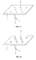
- FIG. 1a shows by way of example and roughly schematically an order plate 1 made of aluminum with - for clarity - only eight circular Recesses 2 for receiving also eight cylindrical spacers 3 (see Figure 1b).
- the order plate with the spacer elements above the glass base of the discharge lamp positioned such that the glass solder wetted ends of the spacer elements just above the surface of the base plate.
- the Distance elements triggered by blowing out of the order plate and pressed onto the base plate. Now stick the spacers 3 by means of Glaslotpaste 5 on the base plate 6 and can in the subsequent manufacturing steps no longer fall over.
- the lamp is on the base plate 6 by means of glass solder a circumferential Frame 7 applied, on each of the four sides of the frame. 7 two glass tablets 8 and then finally a glass Cover plate 9.
- the total of eight approximately 2.4 mm high glass lime tablets 8 serve to first a gap 10 between frame 7 and cover plate. 9 to accomplish.
- the inventive method has the advantage that the spacer elements in the convection current of the joining furnace due to adhesion on the base plate can no longer tip over with glass solder paste. Thereby the committee can be reduced.
Landscapes
- Engineering & Computer Science (AREA)
- Manufacturing & Machinery (AREA)
- Vessels And Coating Films For Discharge Lamps (AREA)
- Manufacture Of Electron Tubes, Discharge Lamp Vessels, Lead-In Wires, And The Like (AREA)
Abstract
Description
- Fig. 1 a
- eine Ordnungsplatte zur Aufnahme von Abstandselementen,
- Fig. 1 b
- die Ordnungsplatte aus Fig. 1 a mit eingesetzten Abstandselementen,
- Fig. 2a
- eine Seitenansicht einer Grundplatte einer Flachlampe mit aufgesetzten Abstandselementen,
- Fig. 2b
- eine Draufsicht der Grundplatte mit den aufgesetzten Abstandselementen aus Fig. 2a,
- Fig. 2c
- die Grundplatte aus Fig. 2a mit vormontiertem Rahmen und Deckplatte,
- Fig. 2d
- die aus Fig. 2c fertig gefügte Flachlampe.
Claims (13)
- Verfahren zur Herstellung einer flachen Entladungslampe, insbesondere einer flachen dielektrischen Barriere-Entladungslampe, deren Entladungsgefäß eine Grundplatte (6), einen Rahmen (7) und eine Deckplatte (9) sowie mindestens ein Abstandselement (3) zwischen Grundplatte (6) und Deckplatte (9) aufweist und mit einem Entladungsmedium gefüllt ist,
gekennzeichnet durch folgende Verfahrensschritte:Bereitstellen eines Lotbades aus Lotpaste,Eintauchen eines Endes des mindestens einen Abstandselements (3) in das Lotbad,Aufbringen des mindestens einen Abstandselements (3) mit dem eingetauchten Ende auf der Innenseite der Grundplatte (6) derart, dass das mindestens eine Abstandselement (3) mittels der Lotpaste (5) des Lotbads auf der Innenseite der Grundplatte (6) haftet. - Verfahren nach Anspruch 1, wobei eine Vielzahl von Abstandselementen (3) jeweilsmit einem Ende in einer Ordnungsplatte (1) aufgenommen und festgehalten werden,mit dem anderen Ende vorübergehend in das Lotbad getaucht werden,mit dem Ende, das in das Lotbad getaucht war auf der Grundplatte (6) aufgebracht werden und schließlichaus der Ordnungsplatte (1) gelöst werden.
- Verfahren nach Anspruch 2, wobei das Festhalten der Abstandselemente (3) in der Ordnungsplatte (1) durch Ansaugen erfolgt.
- Verfahren nach Anspruch 2, wobei das Lösen der Abstandselemente (3) aus der Ordnungsplatte (1) durch Ausblasen erfolgt.
- Verfahren nach einem der vorstehenden Ansprüche, wobei zwischen der Deckplatte (9) und dem Rahmen (7) zumindest ein Zwischenraum (10) als Befüllöffnung zunächst offen gehalten wird.
- Verfahren nach Anspruch 5, wobei der Zwischenraum (10) realisiert wird, indem ein oder mehrere Lottabletten (8) zwischen dem Rahmen (7) und der Deckplatte (9) angeordnet sind.
- Verfahren nach einem der vorstehenden Ansprüche, wobei die Längsausdehnung des mindestens einen Abstandselements (3) senkrecht zur Grundplatte (6) im wesentlichen dem endgültigem Abstand zwischen den Innenseiten von Grund- und Deckplatte (9) entspricht.
- Verfahren nach einem der vorstehenden Ansprüche, wobei die Grundplatte (6) mit dem mindestens einen Abstandselement (3), der Rahmen (7) und die Deckplatte (9) in einem evakuierbaren Ofen zu dem Entladungsgefäß gefügt werden.
- Verfahren nach Anspruch 8, wobei der Ofen während des Fügevorgangs mit dem Entladungsmedium gefüllt ist.
- Verfahren nach Anspruch 8 oder 9, wobei der vormontierte Aufbau aus Grundplatte (6) mit dem mindestens einen Abstandselement (3), der Rahmen (7) und die Deckplatte (9) so orientiert in den Fügeofen eingebracht wird, dass die Innenseite der Grundplatte (6) nach unten zeigt und folglich das mindestens eine Abstandselemente (3) nach unten hängt.
- Verfahren nach einem der vorstehenden Ansprüche, bei dem das Entladungsgefäß Entladungselektroden aufweist, die zumindest zum Teil durch eine dielektrische Schicht von dem Entladungsmedium im Innern des Entladungsgefäßes getrennt sind.
- Verfahren nach Anspruch 11, bei dem die Elektroden als auf der Grundplatte des Entladungsgefäßes angeordnete Elektrodenbahnen ausgebildet sind.
- Verfahren nach einem der vorstehenden Ansprüche, bei dem das Lotbad ein niedrigschmelzendes Glaslot, z.B. Bleiborsilikat, Zinkborat oder auch ein Wismut-basiertes Glaslot umfasst.
Applications Claiming Priority (2)
| Application Number | Priority Date | Filing Date | Title |
|---|---|---|---|
| DE10343073 | 2003-09-17 | ||
| DE10343073A DE10343073A1 (de) | 2003-09-17 | 2003-09-17 | Verfahren zur Herstellung einer flachen Entladungslampe mit Abstandselementen |
Publications (3)
| Publication Number | Publication Date |
|---|---|
| EP1517359A2 true EP1517359A2 (de) | 2005-03-23 |
| EP1517359A3 EP1517359A3 (de) | 2006-06-14 |
| EP1517359B1 EP1517359B1 (de) | 2007-10-10 |
Family
ID=34177801
Family Applications (1)
| Application Number | Title | Priority Date | Filing Date |
|---|---|---|---|
| EP04019086A Expired - Lifetime EP1517359B1 (de) | 2003-09-17 | 2004-08-11 | Verfahren zur Herstellung einer flachen Entladungslampe mit Abstandselementen |
Country Status (9)
| Country | Link |
|---|---|
| US (1) | US20050059312A1 (de) |
| EP (1) | EP1517359B1 (de) |
| JP (1) | JP2005100984A (de) |
| KR (1) | KR100646896B1 (de) |
| CN (1) | CN1599004A (de) |
| AT (1) | ATE375601T1 (de) |
| CA (1) | CA2481289A1 (de) |
| DE (2) | DE10343073A1 (de) |
| TW (1) | TWI261859B (de) |
Families Citing this family (2)
| Publication number | Priority date | Publication date | Assignee | Title |
|---|---|---|---|---|
| DE102005021303A1 (de) * | 2005-05-09 | 2006-11-16 | Patent-Treuhand-Gesellschaft für elektrische Glühlampen mbH | Herstellung von flachen dielektrisch behinderten Entladungslampen |
| TW200700840A (en) * | 2005-06-28 | 2007-01-01 | Delta Optoelectronics Inc | Flat light |
Family Cites Families (11)
| Publication number | Priority date | Publication date | Assignee | Title |
|---|---|---|---|---|
| IT1160700B (it) * | 1977-10-25 | 1987-03-11 | Bfg Glassgroup | Pannelli |
| US4666078A (en) * | 1982-04-20 | 1987-05-19 | Seiko Epson Kabushiki Kaisha | Electroless plated terminals of display panel |
| US5424605A (en) * | 1992-04-10 | 1995-06-13 | Silicon Video Corporation | Self supporting flat video display |
| GB2276270A (en) * | 1993-03-18 | 1994-09-21 | Ibm | Spacers for flat panel displays |
| US5561340A (en) * | 1995-01-31 | 1996-10-01 | Lucent Technologies Inc. | Field emission display having corrugated support pillars and method for manufacturing |
| US6433471B1 (en) * | 1996-01-19 | 2002-08-13 | Philips Electronics North America Corporation | Plasma addressed liquid crystal display with glass spacers |
| US5708325A (en) * | 1996-05-20 | 1998-01-13 | Motorola | Display spacer structure for a field emission device |
| US5811927A (en) * | 1996-06-21 | 1998-09-22 | Motorola, Inc. | Method for affixing spacers within a flat panel display |
| KR100375615B1 (ko) * | 1997-03-21 | 2003-04-18 | 파텐트-트로이한트-게젤샤프트 퓌어 엘렉트리쉐 글뤼람펜 엠베하 | 백그라운드조명을위한평면형형광램프와이러한평면형형광램프를포함하는액정디스플레이장치 |
| DE19817478B4 (de) * | 1998-04-20 | 2004-03-18 | Patent-Treuhand-Gesellschaft für elektrische Glühlampen mbH | Flache Entladungslampe und Verfahren zu ihrer Herstellung |
| US6607118B2 (en) * | 2001-04-30 | 2003-08-19 | Asm Assembly Automation Limited | Apparatus and method for ball release |
-
2003
- 2003-09-17 DE DE10343073A patent/DE10343073A1/de not_active Withdrawn
-
2004
- 2004-08-11 DE DE502004005186T patent/DE502004005186D1/de not_active Expired - Lifetime
- 2004-08-11 AT AT04019086T patent/ATE375601T1/de not_active IP Right Cessation
- 2004-08-11 EP EP04019086A patent/EP1517359B1/de not_active Expired - Lifetime
- 2004-08-26 TW TW093125444A patent/TWI261859B/zh not_active IP Right Cessation
- 2004-09-08 US US10/935,224 patent/US20050059312A1/en not_active Abandoned
- 2004-09-14 KR KR1020040073295A patent/KR100646896B1/ko not_active Expired - Fee Related
- 2004-09-14 CA CA002481289A patent/CA2481289A1/en not_active Abandoned
- 2004-09-15 JP JP2004267752A patent/JP2005100984A/ja not_active Abandoned
- 2004-09-17 CN CNA200410083288XA patent/CN1599004A/zh active Pending
Also Published As
| Publication number | Publication date |
|---|---|
| CN1599004A (zh) | 2005-03-23 |
| TW200523979A (en) | 2005-07-16 |
| ATE375601T1 (de) | 2007-10-15 |
| US20050059312A1 (en) | 2005-03-17 |
| CA2481289A1 (en) | 2005-03-17 |
| TWI261859B (en) | 2006-09-11 |
| DE10343073A1 (de) | 2005-04-21 |
| EP1517359B1 (de) | 2007-10-10 |
| JP2005100984A (ja) | 2005-04-14 |
| KR100646896B1 (ko) | 2006-11-23 |
| DE502004005186D1 (de) | 2007-11-22 |
| KR20050028314A (ko) | 2005-03-22 |
| EP1517359A3 (de) | 2006-06-14 |
Similar Documents
| Publication | Publication Date | Title |
|---|---|---|
| DE60220126T2 (de) | Wechselstrom-Gasentladungsanzeige | |
| DE69732646T2 (de) | Gasentladungsanzeigetafel und verfahren zur herstellung derselben | |
| DE69708822T2 (de) | Herstellungsverfahren einer Plasmaanzeigetafel geeignet für winzige Zellstrukturen, Plasmaanzeigetafel, und Vorrichtung zum Anzeigen der Plasmaanzeigetafel | |
| DE19817478B4 (de) | Flache Entladungslampe und Verfahren zu ihrer Herstellung | |
| DE10227823A1 (de) | Verfahren und Vorrichtung zum Herstellen eines LCD | |
| DE69929537T2 (de) | Herstellungsverfahren einer evakuierten isolierverglasung | |
| DE69118899T2 (de) | Verfahren zur Herstellung von ebenen Plattenleuchtvorrichtungen | |
| EP1517359B1 (de) | Verfahren zur Herstellung einer flachen Entladungslampe mit Abstandselementen | |
| EP1415317B1 (de) | Verfahren zum herstellen einer entladungslampe | |
| DE2261217C3 (de) | Verfahren zum Herstellen von Gasentladungs-Anzeige- oder Speichervorrichtungen | |
| EP1190430A1 (de) | Herstellungsverfahren für eine flache gasentladungslampe | |
| CH621889A5 (de) | ||
| DE1512379B2 (de) | Vorrichtung zur Halterung einer Lochmaske an einem Frontglasrahmen einer Farbfernsehbildröhre | |
| DE2615681C2 (de) | Anzeigevorrichtung mit einem Gasentladungsraum als Elektronenquelle, mit einem Elektronennachbeschleunigungsraum und mit einem Leuchtschirm | |
| EP1022424A2 (de) | Abstandsleiste für Isolierglas | |
| DE19936865A1 (de) | Gasentladungslampe und zugehöriges Herstellungsverfahren | |
| DE1813325C3 (de) | Verfahren zum Zusammenschmelzen eines röhrenförmigen Glassockels mit dem offe nen Ende eines röhrenförmigen Glaskolbens | |
| DE102004023460A1 (de) | Rohrförmige dielektrische Barriere-Entladungslampe und Verfahren zu ihrer Herstellung | |
| EP1415326A1 (de) | Verfahren zum herstellen eines stillen flachstrahlers | |
| EP1430500A2 (de) | Entladungslampe mit stabilisierter entladungsgefässplatte | |
| DE19963838A1 (de) | Getter-Spritzabschirmung | |
| DE1589301A1 (de) | Zwergglimmlampe | |
| DE1464487C (de) | Verfahren zum Herstellen von Kondensatoren | |
| DE102004004478A1 (de) | Verfahren zur Herstellung von Entladungslampen | |
| DD220172A1 (de) | Verfahren zur herstellung flacher gasgefuellter oder vakuumanzeigefelder |
Legal Events
| Date | Code | Title | Description |
|---|---|---|---|
| PUAI | Public reference made under article 153(3) epc to a published international application that has entered the european phase |
Free format text: ORIGINAL CODE: 0009012 |
|
| AK | Designated contracting states |
Kind code of ref document: A2 Designated state(s): AT BE BG CH CY CZ DE DK EE ES FI FR GB GR HU IE IT LI LU MC NL PL PT RO SE SI SK TR |
|
| AX | Request for extension of the european patent |
Extension state: AL HR LT LV MK |
|
| PUAL | Search report despatched |
Free format text: ORIGINAL CODE: 0009013 |
|
| AK | Designated contracting states |
Kind code of ref document: A3 Designated state(s): AT BE BG CH CY CZ DE DK EE ES FI FR GB GR HU IE IT LI LU MC NL PL PT RO SE SI SK TR |
|
| AX | Request for extension of the european patent |
Extension state: AL HR LT LV MK |
|
| 17P | Request for examination filed |
Effective date: 20060710 |
|
| 17Q | First examination report despatched |
Effective date: 20060911 |
|
| AKX | Designation fees paid |
Designated state(s): AT BE DE FR GB NL |
|
| GRAP | Despatch of communication of intention to grant a patent |
Free format text: ORIGINAL CODE: EPIDOSNIGR1 |
|
| GRAS | Grant fee paid |
Free format text: ORIGINAL CODE: EPIDOSNIGR3 |
|
| GRAA | (expected) grant |
Free format text: ORIGINAL CODE: 0009210 |
|
| AK | Designated contracting states |
Kind code of ref document: B1 Designated state(s): AT BE DE FR GB NL |
|
| REG | Reference to a national code |
Ref country code: GB Ref legal event code: FG4D Free format text: NOT ENGLISH |
|
| REF | Corresponds to: |
Ref document number: 502004005186 Country of ref document: DE Date of ref document: 20071122 Kind code of ref document: P |
|
| NLV1 | Nl: lapsed or annulled due to failure to fulfill the requirements of art. 29p and 29m of the patents act | ||
| PG25 | Lapsed in a contracting state [announced via postgrant information from national office to epo] |
Ref country code: NL Free format text: LAPSE BECAUSE OF FAILURE TO SUBMIT A TRANSLATION OF THE DESCRIPTION OR TO PAY THE FEE WITHIN THE PRESCRIBED TIME-LIMIT Effective date: 20071010 |
|
| GBV | Gb: ep patent (uk) treated as always having been void in accordance with gb section 77(7)/1977 [no translation filed] | ||
| EN | Fr: translation not filed | ||
| PLBE | No opposition filed within time limit |
Free format text: ORIGINAL CODE: 0009261 |
|
| STAA | Information on the status of an ep patent application or granted ep patent |
Free format text: STATUS: NO OPPOSITION FILED WITHIN TIME LIMIT |
|
| 26N | No opposition filed |
Effective date: 20080711 |
|
| PG25 | Lapsed in a contracting state [announced via postgrant information from national office to epo] |
Ref country code: FR Free format text: LAPSE BECAUSE OF FAILURE TO SUBMIT A TRANSLATION OF THE DESCRIPTION OR TO PAY THE FEE WITHIN THE PRESCRIBED TIME-LIMIT Effective date: 20080725 |
|
| PG25 | Lapsed in a contracting state [announced via postgrant information from national office to epo] |
Ref country code: GB Free format text: LAPSE BECAUSE OF FAILURE TO SUBMIT A TRANSLATION OF THE DESCRIPTION OR TO PAY THE FEE WITHIN THE PRESCRIBED TIME-LIMIT Effective date: 20071010 |
|
| PG25 | Lapsed in a contracting state [announced via postgrant information from national office to epo] |
Ref country code: BE Free format text: LAPSE BECAUSE OF NON-PAYMENT OF DUE FEES Effective date: 20080831 |
|
| PG25 | Lapsed in a contracting state [announced via postgrant information from national office to epo] |
Ref country code: AT Free format text: LAPSE BECAUSE OF NON-PAYMENT OF DUE FEES Effective date: 20080811 |
|
| PGFP | Annual fee paid to national office [announced via postgrant information from national office to epo] |
Ref country code: DE Payment date: 20091019 Year of fee payment: 6 |
|
| REG | Reference to a national code |
Ref country code: DE Ref legal event code: R119 Ref document number: 502004005186 Country of ref document: DE Effective date: 20110301 |
|
| PG25 | Lapsed in a contracting state [announced via postgrant information from national office to epo] |
Ref country code: DE Free format text: LAPSE BECAUSE OF NON-PAYMENT OF DUE FEES Effective date: 20110301 |