EP1517314A2 - Fokussiervorrichtung für optisches Plattenlaufwerk - Google Patents
Fokussiervorrichtung für optisches Plattenlaufwerk Download PDFInfo
- Publication number
- EP1517314A2 EP1517314A2 EP04009548A EP04009548A EP1517314A2 EP 1517314 A2 EP1517314 A2 EP 1517314A2 EP 04009548 A EP04009548 A EP 04009548A EP 04009548 A EP04009548 A EP 04009548A EP 1517314 A2 EP1517314 A2 EP 1517314A2
- Authority
- EP
- European Patent Office
- Prior art keywords
- control signal
- error term
- actuator control
- actuator
- signal
- Prior art date
- Legal status (The legal status is an assumption and is not a legal conclusion. Google has not performed a legal analysis and makes no representation as to the accuracy of the status listed.)
- Granted
Links
- 230000003287 optical effect Effects 0.000 title claims abstract description 25
- 230000006978 adaptation Effects 0.000 claims abstract description 19
- 238000005070 sampling Methods 0.000 claims abstract description 5
- 238000000034 method Methods 0.000 claims description 16
- 230000001105 regulatory effect Effects 0.000 claims 3
- 230000008859 change Effects 0.000 description 5
- 238000010586 diagram Methods 0.000 description 5
- 230000006870 function Effects 0.000 description 5
- 230000010363 phase shift Effects 0.000 description 4
- 238000013459 approach Methods 0.000 description 2
- 238000004364 calculation method Methods 0.000 description 2
- 239000011248 coating agent Substances 0.000 description 2
- 238000000576 coating method Methods 0.000 description 2
- 238000013461 design Methods 0.000 description 2
- 238000001914 filtration Methods 0.000 description 2
- 230000004044 response Effects 0.000 description 2
- 239000000725 suspension Substances 0.000 description 2
- 230000003044 adaptive effect Effects 0.000 description 1
- 230000003466 anti-cipated effect Effects 0.000 description 1
- 230000009286 beneficial effect Effects 0.000 description 1
- 230000000295 complement effect Effects 0.000 description 1
- 230000008878 coupling Effects 0.000 description 1
- 238000010168 coupling process Methods 0.000 description 1
- 238000005859 coupling reaction Methods 0.000 description 1
- 230000000694 effects Effects 0.000 description 1
- 238000005516 engineering process Methods 0.000 description 1
- 238000003780 insertion Methods 0.000 description 1
- 230000037431 insertion Effects 0.000 description 1
- 230000003993 interaction Effects 0.000 description 1
- 238000002372 labelling Methods 0.000 description 1
- 238000005259 measurement Methods 0.000 description 1
- 230000008569 process Effects 0.000 description 1
Images


Classifications
-
- G—PHYSICS
- G11—INFORMATION STORAGE
- G11B—INFORMATION STORAGE BASED ON RELATIVE MOVEMENT BETWEEN RECORD CARRIER AND TRANSDUCER
- G11B7/00—Recording or reproducing by optical means, e.g. recording using a thermal beam of optical radiation by modifying optical properties or the physical structure, reproducing using an optical beam at lower power by sensing optical properties; Record carriers therefor
- G11B7/08—Disposition or mounting of heads or light sources relatively to record carriers
- G11B7/09—Disposition or mounting of heads or light sources relatively to record carriers with provision for moving the light beam or focus plane for the purpose of maintaining alignment of the light beam relative to the record carrier during transducing operation, e.g. to compensate for surface irregularities of the latter or for track following
-
- G—PHYSICS
- G11—INFORMATION STORAGE
- G11B—INFORMATION STORAGE BASED ON RELATIVE MOVEMENT BETWEEN RECORD CARRIER AND TRANSDUCER
- G11B7/00—Recording or reproducing by optical means, e.g. recording using a thermal beam of optical radiation by modifying optical properties or the physical structure, reproducing using an optical beam at lower power by sensing optical properties; Record carriers therefor
- G11B7/002—Recording, reproducing or erasing systems characterised by the shape or form of the carrier
- G11B7/0037—Recording, reproducing or erasing systems characterised by the shape or form of the carrier with discs
-
- G—PHYSICS
- G11—INFORMATION STORAGE
- G11B—INFORMATION STORAGE BASED ON RELATIVE MOVEMENT BETWEEN RECORD CARRIER AND TRANSDUCER
- G11B7/00—Recording or reproducing by optical means, e.g. recording using a thermal beam of optical radiation by modifying optical properties or the physical structure, reproducing using an optical beam at lower power by sensing optical properties; Record carriers therefor
- G11B7/08—Disposition or mounting of heads or light sources relatively to record carriers
- G11B7/09—Disposition or mounting of heads or light sources relatively to record carriers with provision for moving the light beam or focus plane for the purpose of maintaining alignment of the light beam relative to the record carrier during transducing operation, e.g. to compensate for surface irregularities of the latter or for track following
- G11B7/0908—Disposition or mounting of heads or light sources relatively to record carriers with provision for moving the light beam or focus plane for the purpose of maintaining alignment of the light beam relative to the record carrier during transducing operation, e.g. to compensate for surface irregularities of the latter or for track following for focusing only
Definitions
- FES focus error signal
- An initial difficulty in focusing on the label side of the disk is that the FES signal provides a low signal-to-noise ratio, in part due to the nature of the media used to cover the label side of the disk. Because of the low signal-to-noise ratio, conventional use of a FES signal configured in a closed-loop feedback circuit will not effectively provide signals to the actuator focus coil which result in convergence on the intended focal point, i.e. the surface of the disk.
- a second difficulty in using the FES signal in a conventional manner is that the OPU is configured to have an at-rest focal point that is further from the laser and optics than the surface of the label side of the disk. This is because the OPU is designed to focus on data pits defined within the optical disk, approximately 1.2 mm from the surface of the data side of the disk. Thus, the laser and optics are out-of-focus when in the at-rest position.
- a system for providing an actuator control signal to an actuator within an optical pickup unit of an optical disk drive, focuses optics on an optical disk.
- an error term is obtained by sampling the FES (focus error signal) signal.
- the error term is scaled by an adaptation coefficient, which regulates a rate at which the error term modifies the actuator control signal.
- An actuator control signal generator generates the actuator control signal to control movement of the actuator, wherein the actuator control signal is a function of a prior actuator position, the error signal and the adaptation coefficient.
- Fig. 1 is a diagrammatic view of an exemplary implementation of an optical disk drive.
- Fig. 2 is a block diagram showing an exemplary implementation of a feed forward engine contained within firmware of the diagrammatic view of the optical disk drive of Fig. 1.
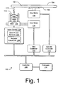
- Fig. 3 is a view of an optical disk, illustrating exemplary division of the disk into a plurality of sectors.
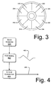
- Fig. 4 is a block diagram showing an exemplary implementation of portions of the feed forward engine.
- Fig. 5 is a flow diagram illustrating an exemplary implementation focusing optics within an optical drive.
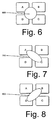
- Fig. 6 is a diagrammatic view of a quad sensor, illustrating an in-focus condition.
- Figs. 7 and 8 are diagrams similar to that of Fig. 6, in which the quad sensor detects out-of-focus conditions wherein the optics focus too dose and too far, relative to the focal point.
- Fig. 1 shows a somewhat diagrammatic view of an exemplary disk drive and controller system 100.
- a disk 102 having an information side 104 is oriented to position a label side 106 for marking.
- the disk is rotated by a disk or spindle motor 108, which is controlled by a spindle controller 110.
- a laser beam 112 strikes a coated surface of the label side 106 of the disk 102 after passing through optics, such as a lens 114.
- a laser 116 is carried by a sled 118, which is moved in a radial direction by a sled motor 120.
- the sled motor 120 advances the sled 118, carrying the laser 116, in incremental steps from a radially inner edge of the label region, to a radially outer edge of the label region under the direction of a sled controller 122.
- a laser controller 124 controls the operation of the laser 116 and associated tracking coils and sensors.
- a quad focus sensor 126 typically contains four sensors, and is designed to facilitate focusing generally, in part by sensing the distance between the laser and the disk.
- the operation of the quad focus sensors may be understood with reference to Figs. 6-8.
- the four quad sensors, labeled A-D are seen.
- the output of the quad sensors may be used to form both the FES (focus error signal) and the SUM signal.
- Reflected light 700 is seen in a generally circular configuration, which implies that each sensor is similarly affected. Accordingly, the FES signal is approximately zero (0) volts.
- Figs. 7 and 8 illustrate conditions wherein the reflected light 800, 900 indicates that the optics is in front of, and behind, the focal point.
- the outputs of the four sensors are combined to form the SUM signal, (or the difference of the diagonals is used to form the FES signal), both of which are discussed below.
- An actuator focus coil 128 is configured to adjust the optics 114 to focus the laser 116 at points both toward and away from, the disk 102.
- a controller 130 controls the operation of the exemplary disk drive and controller system 100.
- the controller 130 is configured to execute program statements such as those contained in firmware 132.
- Fig. 2 shows an exemplary feed forward engine 200, which may be defined by program statements contained within firmware 132 for execution by the processor or controller 130.
- the feed forward engine 200 receives one or more inputs and provides as output an actuator control signal 202, which can be fed into the actuator focus coil 128 (Fig. 1) to control the focus of the laser 116, optics 114 and associated assembly.
- the exemplary feed forward engine 200 receives inputs including a FES (focus error signal) signal 204 from the quad focus sensors 126 (Fig. 1), the SUM signal 203 (also from the quad focus sensors) and an angle theta 206 which describes the angular orientation of the disk 102 (Fig. 1) within the optical drive 100 (Fig. 1).
- FES focus error signal
- a coefficient Mu 208 is also provided to the feed forward engine.
- the coefficient Mu balances a rate at which the FES signal 204 is used to modify a current voltage applied to the actuator focus coil 128. This is important, in part because the FES signal is typically fairly noisy, when used to focus on the label side 106 of the disk 102. In part because the FES signal was not intended for use in focusing the laser optics on the label side 106 of the disk 102, the standard approach of using a high bandwidth feedback loop does not work well. Accordingly, the FES signal is scaled by one or more factors, such as Mu.
- the value of the Mu input 208 may be more fully understood by realizing that if the FES signal is allowed to overly influence a present value of the voltage input to the actuator coil 128, the actuator coil 128 may swing too wildly and fail to converge, i.e. focus the laser on the label surface 106 of the disk. This is due in large part to the differences encountered when focusing on the coating on the surface 106 of the disk 102, rather than on data pits defined within the interior of the disk, as is conventionally done. In a worst case situation, if Mu were not used to damp changes brought on by wild swings in the value of the FES signal, the focal point may leave a region within which the FES signal may be detected; this could cause a complete failure to focus.
- the laser may not respond quickly enough to changing conditions, and may fail to focus. Accordingly, the value of Mu input 208 should be selected according to the specific application to result in proper focus.
- a baseline actuator positioning routine 210 is configured to determine a baseline voltage level for application to the actuator focus coil 128, to result in an associated baseline actuator position and focus optics position on the surface 106 of the disk 102.
- the actuator 128 has an inherent, initial or at-rest position, which may reflect an Inherent or default voltage applied to the coil, or which may reflect the coil being allowed to "float" at an initial voltage level.
- the focal optics moved by the actuator have an inherent, default or at-rest focal point.
- the optics 114 are designed to focus on a location within the disk, the at-rest position of the actuator 128 and optics 114 is typically too close to the disk to result in proper focus on the disk surface 106 without application of a signal to the actuator 128.
- the baseline actuator positioning routine 210 determines the baseline voltage level. It is sometimes the case that the baseline voltage has an AC component, i.e. the baseline voltage may vary as a function of the angular orientation (i.e. the spin) of the disk. Such an AC component can vary according to the sectors of Fig. 3, or as a function of the angular disk orientation. Such an AC component allows the baseline voltage to vary the actuator focus coil 128 to maintain the focus of the optics 114 on the surface 106 of the disk 102, even where the disk is warped, wedge-shaped, or otherwise imperfect.
- the baseline actuator positioning routine 210 is configured to apply an initial voltage to the actuator coil 128 to move the focal point of the optics 114 away from the disk 102 (Fig. 1) by an amount calculated to counteract an initial design assumption typically built into the actuator coil.
- the design assumption is that the focus point should be inside the plastic disk 102, to facilitate data reading and writing.
- the focus point should be on the disk surface.
- a baseline voltage may be estimated to result in movement of the actuator coil 128, and an associated change in the focal point of the optics 114, which retracts the focal point by an appropriate fraction of the thickness of the optical disk 102, thereby causing the focal point to be (approximately) on the surface 106 of the disk 102.
- the above first exemplary implementation of the baseline positioning routine 210 makes a first assumption that the optics 114. is focused on a point a known depth beneath the surface 106 of the disk 102, and a second assumption that a voltage can be calculated to move the focal point to the surface of the disk.
- a second implementation of the baseline positioning routine 210 is based on the use of objective measurements.
- the baseline actuator positioning routine 210 is configured to move the optics 114 through a full range of focus, i.e. from focusing too near to focusing too far away.
- the baseline actuator positioning routine 210 is configured to step the actuator coil 128 through this range incrementally, and to record values obtained from the SUM.
- the maximum value of the SUM signal is recorded. This value may be assumed to have occurred when the optics was approximately in focus; additionally, the voltage which resulted in the position of the optics may be taken as the baseline voltage.
- DC voltage may again be stepped incrementally into the actuator focus coil to move the optics 114 until the SUM signal is approximately 75% (more or less) of the maximum recorded during the first application of incremental voltages to the actuator coil 128.
- This DC voltage level may be used as the baseline voltage level.
- Fig. 3 illustrates a disk logically divided into 8 sectors 302-316. Each of the sectors could be assigned a different baseline voltage, thereby reducing focus error in each sector. Accordingly. the baseline voltage may include an alternating current component.
- the quad focus sensors 126 may be better understood by briefly referring to Fig. 4.
- the quad sensors 126 are typically optical sensors which respond to a reflection of the laser light 112.
- the FES (focus error signal) signal 204 is the difference of the sum of the diagonal sensors (i.e. upper left plus lower right, minus upper right plus lower left).
- An exemplary FES signal 400 is seen to the right of box 402 in Fig. 4.
- the FES signal is zero where the optics 114-116 are out of focus. As the optics move into focus, the FES signal becomes positive triangle wave. As the optics moves out of focus, the FES signal becomes a negative triangle wave. Note that the FES signal 400 is for illustration purposes only; a real FES signal would contain considerably noisier.
- the error term generator 212 is configured to process the FES (focus error signal) signal 402 to create an error term 204 (Fig. 4).
- an A-to-D converter 404 (Fig. 4) enables the error term generator 212 to translate the FES signal into a digital error term 204.
- the digital values of the FES signal are suitable for insertion into equations to generate coefficients for Fourier series terms, as will be seen in greater detail below.
- An actuator control signal generator 216 generates the signal 202 applied to the actuator focus coil 128.
- the output of the signal generator 216 is typically a digital value, which is converted to an analog signal via a DAC (digital to analog converter) for coupling to the actuator focus coil 128.
- the actuator control signal generator 216 may be configured in a number of ways.
- a coefficient generator 218 is configured to generate coefficients for a Fourier series and a Fourier subroutine 220 is configured to utilize the coefficients generated to generate the signal for application to the actuator focus coil.
- the above equations provide five new coefficients (e.g. A0 (new)) using the five previous old coefficients (e.g A0(old)).
- a new value for each coefficient is calculated 400 times per revolution of the disk 102. (although 400 such calculations per revolution is effective, other rates of calculation could be substituted, depending on application.)
- the error values, Ek would change 400 times per revolution, as the FES signal was sampled.
- the values for the sinusoidal terms QS1 through QC2
- the initial value of A0 is the baseline value calculated by the baseline actuator positioning routine 210, and the initial values for A1-B2 are zero.
- a Fourier routine 220 is configured to use the coefficients from the coefficient generator 218 and the angle of the disk rotation to produce the actuator control signal 202.
- QS1 and QC2 are the sine and cosine values, respectively, for the given value of an angle theta and two times theta, respectively, for the first and second harmonic, respectively.
- the actuator control signal generator 216 can be implemented without coefficients and a Fourier series.
- LMS least mean squares
- the phase of terms within the actuator control signal are shifted to the degree necessary compensate for actuator harmonics (e.g. an actuator resonant frequency). This may be necessary if an angular disk speed of the optical disk drive is sufficiently high.
- exemplary disk speed (rpm) could be associated with a degree to which the actuator control signal is phase-shifted. The degree of the phase shift applied would generally have to be determined by experimentation on the actuator available. Accordingly, a table could associate disk speed rpm with a phase-shift of the actuator control signal.
- the flowchart of Fig. 5 illustrates a further exemplary implementation, wherein a method 500 is employed to focus the optics of an optical disk drive 100.
- the elements of the method may be performed by any desired means, such as by the execution of processor-readable instructions defined on a processor-readable media, such as a disk, a ROM or other memory device or by operation of an application specific integrated circuit (ASIC) or other hardware device.
- the ROM may contain the firmware 132 of Fig. 1, thereby implementing the feed forward engine 200 of Fig. 2 according to a method such as the exemplary method as seen in the flow chart of Fig. 5.
- an ASIC may contain logic which implements the feed forward engine 200.
- actions described in any block may be performed in parallel with actions described in other blocks, may occur in an alternate order, or may be distributed in a manner which associates actions with more than one other block.
- a baseline actuator control signal is generated.
- the baseline actuator control signal when applied to the actuator focus coil 128, results in the laser focusing sufficiently that the SUM and FES signals obtained from the quad focus sensors 126 are non-zero.
- the baseline actuator control signal may be generated in a number of ways.
- the first exemplary implementation of the baseline actuator positioning routine 210 described above, may be utilized. Recall that in that method, the baseline actuator signal was generated by assumptions made as to the location of the at-rest focal point and the signal required for application to the actuator focus coil 128 to move the focal point to the surface 106 of the disk 102.
- the second exemplary implementation of the baseline actuator positioning routine 210 may be utilized.
- a range of voltages was applied to the actuator focus coil 128 and the SUM and/or FES signal was monitored.
- a signal applied to the focus actuator coil 128 associated with a near optimal value of the SUM and/or FES signal could be utilized.
- a baseline voltage could be selected from the stepped voltage level when the SUM signal was near the high SUM value.
- an error term is generated.
- the error term may be generated by the error term generator 212, using the FES (focus error signal), as seen above.
- the FES signal is converted into a digital value, which may be used as the error term.
- an actuator control signal 202 is generated using the error term and other terms.
- the actuator control signal 202 may be generated by the actuator control signal generator 216 of the feed forward engine 200.
- a number of exemplary, alternative and/or complementary implementations of the method by which the actuator control signal 202 is generated are shown in blocks 508-512.
- coefficients are generated and a Fourier series is summed.
- a coefficient generator 216 can generate coefficients for use in a Fourier series.
- the Fourier subroutine 220 using the coefficients and a value for the angle of the disk orientation 206, determines the actuator control signal 202.
- This actuator control signal which has been updated via the coefficient generator 216, becomes the new baseline signal for the next adaptation cycle.
- the coefficient generator 218 can be modified to compensate for the interaction. This optional implementation was discussed with reference to the coefficient generator 218, in the discussion of Fig. 2, above.
- the actuator control signal generator 216 can be implemented without Fourier coefficients and without a Fourier series. As seen above, such a generalized feed forward scheme could be implemented wherein no predetermined shape to the feed forward signals is defined.
- a label image is applied to the label surface 106 of the disk 102.
- the feed forward engine 200 continuously provides an actuator control signal 202 to the focus actuator coil 128, enabling the optics 114 to maintain the focus of the laser 116 on the surface of the disk.
- the laser beam 112 then applies an image to the coating on the surface 106 of the disk 102.
Landscapes
- Optical Recording Or Reproduction (AREA)
Applications Claiming Priority (2)
| Application Number | Priority Date | Filing Date | Title |
|---|---|---|---|
| US10/661,752 US20050058031A1 (en) | 2003-09-12 | 2003-09-12 | Optical disk drive focusing apparatus |
| US661752 | 2003-09-12 |
Publications (3)
| Publication Number | Publication Date |
|---|---|
| EP1517314A2 true EP1517314A2 (de) | 2005-03-23 |
| EP1517314A3 EP1517314A3 (de) | 2007-10-03 |
| EP1517314B1 EP1517314B1 (de) | 2012-08-29 |
Family
ID=34194709
Family Applications (1)
| Application Number | Title | Priority Date | Filing Date |
|---|---|---|---|
| EP04009548A Expired - Lifetime EP1517314B1 (de) | 2003-09-12 | 2004-04-22 | Fokussiervorrichtung für optisches Plattenlaufwerk |
Country Status (7)
| Country | Link |
|---|---|
| US (1) | US20050058031A1 (de) |
| EP (1) | EP1517314B1 (de) |
| JP (1) | JP2005093050A (de) |
| KR (1) | KR20050027031A (de) |
| CN (1) | CN1595509A (de) |
| SG (1) | SG110105A1 (de) |
| TW (1) | TWI335031B (de) |
Cited By (2)
| Publication number | Priority date | Publication date | Assignee | Title |
|---|---|---|---|---|
| KR20050027031A (ko) * | 2003-09-12 | 2005-03-17 | 휴렛-팩커드 디벨롭먼트 컴퍼니, 엘 피 | 포커싱 방법, 시스템 및 프로세서 판독 가능 매체 |
| US7995431B2 (en) | 2005-05-23 | 2011-08-09 | Renesas Electronics Corporation | Optical disc device |
Families Citing this family (5)
| Publication number | Priority date | Publication date | Assignee | Title |
|---|---|---|---|---|
| JPWO2006114888A1 (ja) * | 2005-04-25 | 2008-12-11 | 株式会社ルネサステクノロジ | 光ディスク装置 |
| US7889220B2 (en) * | 2006-10-31 | 2011-02-15 | Hewlett-Packard Development Company, L.P. | Device and method for maintaining optical energy density on a medium |
| US7633704B2 (en) * | 2008-04-28 | 2009-12-15 | Seagate Technology Llc | Regulating tuning rate of adaptive filter coefficients for feed-forward disturbance rejection in a servo control loop |
| US8542455B2 (en) | 2011-11-16 | 2013-09-24 | Western Digital Technologies, Inc. | Disk drive upsampling servo control signal |
| US9099133B1 (en) | 2013-01-29 | 2015-08-04 | Western Digital Technologies, Inc. | Disk drive servo control using hybrid upsample filter |
Citations (5)
| Publication number | Priority date | Publication date | Assignee | Title |
|---|---|---|---|---|
| EP0805439A1 (de) | 1996-05-03 | 1997-11-05 | Eastman Kodak Company | Ausgleich für radiale und vertikale Rundlauffehler einer optischen Platte |
| US6239572B1 (en) | 1999-02-12 | 2001-05-29 | Pioneer Corporation | Servo control apparatus |
| US20020136111A1 (en) | 2001-01-25 | 2002-09-26 | Kadlec Ron J. | Optical disk drive with a digital focus and tracking servo system |
| US20020191517A1 (en) | 2000-10-30 | 2002-12-19 | Kazuhiko Honda | Method of printing label on optical disk, optical disk unit, and optical disk |
| JP2003242669A (ja) | 2002-02-15 | 2003-08-29 | Yamaha Corp | 光ディスク装置、フォーカス制御方法およびプログラム |
Family Cites Families (54)
| Publication number | Priority date | Publication date | Assignee | Title |
|---|---|---|---|---|
| US4027217A (en) * | 1975-02-12 | 1977-05-31 | Pertec Computer Corporation | Speed control for a motor |
| US4628379A (en) * | 1984-09-25 | 1986-12-09 | Amcodyne Incorporated | Disk runout compensator |
| US4967286A (en) * | 1988-12-12 | 1990-10-30 | Disctronics Manufacturing, Inc. | Method and apparatus for forming a digital image on an optical recording disc |
| US5251194A (en) * | 1989-04-17 | 1993-10-05 | Mitsubishi Denki Kabushiki Kaisha | Techniques for controlling beam position and focus in optical disk drives |
| US5182741A (en) * | 1989-08-25 | 1993-01-26 | Sharp Kabushiki Kaisha | Optical disk recording/reproducing device utilizing a constant angular velocity method with a constant linear velocity formatted optical disk |
| US5164932A (en) * | 1990-09-28 | 1992-11-17 | International Business Machines Corporation | Acquiring a best focus using a focus signal offset |
| JP3109866B2 (ja) * | 1990-11-17 | 2000-11-20 | 太陽誘電株式会社 | 光学式情報記録担体用基板及びその製造方法 |
| KR940010649A (ko) * | 1992-10-14 | 1994-05-26 | 오오가 노리오 | 인쇄장치와 감광지 |
| US5688173B1 (en) * | 1993-03-31 | 1999-10-05 | Sega Enterprises Kk | Information storage medium and electronic device using the same |
| DE4311683C2 (de) * | 1993-04-08 | 1996-05-02 | Sonopress Prod | Plattenförmiger optischer Speicher und Verfahren zu dessen Herstellung |
| US6102800A (en) * | 1993-07-28 | 2000-08-15 | Sega Enterprises, Ltd. | Information storage medium and electronic device using the same |
| TW399749U (en) * | 1993-07-28 | 2000-07-21 | Sega Enterprises Kk | Data recording medium and electronic device using this medium |
| EP0643391B1 (de) * | 1993-09-07 | 2000-02-02 | Hitachi, Ltd. | Informationsaufzeichnungsträger, optische Platten und Wiedergabesystem |
| JP3318795B2 (ja) * | 1993-10-08 | 2002-08-26 | ソニー株式会社 | 変位検出装置 |
| US5550685A (en) * | 1993-10-22 | 1996-08-27 | Syquest Technology, Inc. | Applying an adaptive feed-forward algorithm as a frequency selective filter in a closed loop disk drive servo system in order to compensate for periodic perturbations which otherwise appear in the servo system position error signal |
| US5627895A (en) * | 1993-11-29 | 1997-05-06 | Sega Enterprises, Ltd. | Electronic device for detecting selected visually perceptible indication information on an information storage medium for security comparison |
| TW264553B (de) * | 1994-04-26 | 1995-12-01 | Hitachi Building System Service Kk | |
| JPH08180463A (ja) * | 1994-12-20 | 1996-07-12 | Pioneer Video Corp | 光学式ディスク |
| JPH08194972A (ja) * | 1995-01-12 | 1996-07-30 | Pioneer Video Corp | 光ディスク及びその製造装置 |
| JP3300186B2 (ja) * | 1995-02-28 | 2002-07-08 | パイオニア株式会社 | 光ディスクプレーヤ |
| JP3465413B2 (ja) * | 1995-06-16 | 2003-11-10 | ソニー株式会社 | 光ディスク駆動装置およびフォーカス制御方法 |
| US5729533A (en) * | 1995-09-12 | 1998-03-17 | Wae Manufacturing Inc. | Two-sided, light-readable information recording disc stacks and methods of making same |
| JPH09128770A (ja) * | 1995-10-30 | 1997-05-16 | Alpine Electron Inc | フォーカスサーボ制御装置 |
| GB9605729D0 (en) * | 1996-03-19 | 1996-05-22 | Applied Holographics | Optical data storage disc |
| US5764430A (en) * | 1996-04-01 | 1998-06-09 | International Business Machines Corporation | Disk drive having optimized spindle speed for environment |
| US5958651A (en) * | 1996-07-11 | 1999-09-28 | Wea Manufacturing Inc. | Methods for providing artwork on plastic information discs |
| US6195322B1 (en) * | 1996-07-25 | 2001-02-27 | Sony Corporation | Disk drive device and method of setting rotational speed thereof |
| JP2845230B2 (ja) * | 1996-12-16 | 1999-01-13 | 日本電気株式会社 | 光ディスク装置のビームスポット速度検出器 |
| US6019151A (en) * | 1997-01-07 | 2000-02-01 | Eastman Kodak Company | Printing onto discs such as compact discs and the like |
| US5781221A (en) * | 1997-02-28 | 1998-07-14 | Eastman Kodak Company | Method of printing visually readable information on a compact disk |
| US5915858A (en) * | 1997-03-07 | 1999-06-29 | Eastman Kodak Company | Organizing pixels of different density levels for printing human readable information on CDs |
| US5766495A (en) * | 1997-03-13 | 1998-06-16 | Wea Manufacturing Inc. | Methods for providing generic and specific artwork on plastic information discs |
| EP0867881A3 (de) * | 1997-03-26 | 2002-10-23 | Sony Corporation | Auzeichnungsgerät für Aufzeichnungsmedium, Methode und Aufzeichnungsmedium |
| US5949752A (en) * | 1997-10-30 | 1999-09-07 | Wea Manufacturing Inc. | Recording media and methods for display of graphic data, text, and images |
| KR100282939B1 (ko) * | 1997-11-25 | 2001-03-02 | 윤종용 | 광디스크드라이브에서의 스핀들모터 회전속도 제어방법 |
| US6270176B1 (en) * | 1997-12-11 | 2001-08-07 | Compulog Corporation | Method and apparatus for printing labels on digital recording media |
| US6074031A (en) * | 1997-12-11 | 2000-06-13 | Compulog Corporation | Method and apparatus for printing labels on digital recording media |
| US6440248B1 (en) * | 1998-02-02 | 2002-08-27 | Wea Manufacturing Inc. | Two-sided graphical image DVDs and methods for making same |
| US5997976A (en) * | 1998-02-12 | 1999-12-07 | Wea Manufacturing Inc. | Etched mold surface for use in making light-readable discs |
| WO1999044196A1 (en) * | 1998-02-27 | 1999-09-02 | Doug Carson & Associates, Inc. | Individual adjustment of pit and land transition locations in an optical disc mastering process |
| US5967676A (en) * | 1998-03-31 | 1999-10-19 | Microtech Conversion Systems, Inc. | Image orientation system for disk printing |
| US6264295B1 (en) * | 1998-04-17 | 2001-07-24 | Elesys, Inc. | Radial printing system and methods |
| US6386667B1 (en) * | 1998-04-24 | 2002-05-14 | Hewlett-Packard Company | Technique for media coverage using ink jet writing technology |
| US6384929B1 (en) * | 1998-06-17 | 2002-05-07 | Wordtech, Inc. | Self-orienting printer controller for printing on the non-recordable label face of a compact disk |
| US6124011A (en) * | 1998-09-03 | 2000-09-26 | Wea Manufacturing, Inc. | Information-bearing discs and methods of fabrication |
| US6202550B1 (en) * | 1998-12-30 | 2001-03-20 | Eastman Kodak Company | Printer and method for printing indicia on a compact disk using a plurality of ink jet or laser rotatable print heads |
| US6403191B1 (en) * | 1999-09-21 | 2002-06-11 | Strata-Tac, Inc. | Laminate with integrated compact disk label and methods |
| US6452883B2 (en) * | 2000-02-24 | 2002-09-17 | Via Technologies, Inc. | Method and apparatus applied in an optical storage device for estimating radial speed of disc |
| JP2001266367A (ja) * | 2000-03-17 | 2001-09-28 | Matsushita Electric Ind Co Ltd | 光ディスク装置 |
| US6765848B2 (en) * | 2001-01-10 | 2004-07-20 | Infineon Technologies North America Corp. | Focus and tracking repeatable runout compensator |
| US6813226B2 (en) * | 2001-01-25 | 2004-11-02 | Dphi Acquisitions, Inc. | Calibration of a focus sum threshold in a focus servo system |
| KR100416593B1 (ko) * | 2001-03-30 | 2004-02-05 | 삼성전자주식회사 | 편심에러를 보상하는 광디스크 재생장치. |
| KR100408288B1 (ko) * | 2001-06-20 | 2003-12-03 | 삼성전자주식회사 | 편심 보상을 위한 디스크 드라이브 서보 시스템 및 외란보상 방법 |
| US20050058031A1 (en) * | 2003-09-12 | 2005-03-17 | Hanks Darwin Mitchel | Optical disk drive focusing apparatus |
-
2003
- 2003-09-12 US US10/661,752 patent/US20050058031A1/en not_active Abandoned
-
2004
- 2004-04-14 TW TW093110362A patent/TWI335031B/zh not_active IP Right Cessation
- 2004-04-22 EP EP04009548A patent/EP1517314B1/de not_active Expired - Lifetime
- 2004-07-12 CN CNA2004100699328A patent/CN1595509A/zh active Pending
- 2004-07-29 SG SG200404301A patent/SG110105A1/en unknown
- 2004-09-09 KR KR1020040072121A patent/KR20050027031A/ko not_active Ceased
- 2004-09-10 JP JP2004263315A patent/JP2005093050A/ja active Pending
Patent Citations (5)
| Publication number | Priority date | Publication date | Assignee | Title |
|---|---|---|---|---|
| EP0805439A1 (de) | 1996-05-03 | 1997-11-05 | Eastman Kodak Company | Ausgleich für radiale und vertikale Rundlauffehler einer optischen Platte |
| US6239572B1 (en) | 1999-02-12 | 2001-05-29 | Pioneer Corporation | Servo control apparatus |
| US20020191517A1 (en) | 2000-10-30 | 2002-12-19 | Kazuhiko Honda | Method of printing label on optical disk, optical disk unit, and optical disk |
| US20020136111A1 (en) | 2001-01-25 | 2002-09-26 | Kadlec Ron J. | Optical disk drive with a digital focus and tracking servo system |
| JP2003242669A (ja) | 2002-02-15 | 2003-08-29 | Yamaha Corp | 光ディスク装置、フォーカス制御方法およびプログラム |
Cited By (4)
| Publication number | Priority date | Publication date | Assignee | Title |
|---|---|---|---|---|
| KR20050027031A (ko) * | 2003-09-12 | 2005-03-17 | 휴렛-팩커드 디벨롭먼트 컴퍼니, 엘 피 | 포커싱 방법, 시스템 및 프로세서 판독 가능 매체 |
| US7995431B2 (en) | 2005-05-23 | 2011-08-09 | Renesas Electronics Corporation | Optical disc device |
| US8780680B2 (en) | 2005-05-23 | 2014-07-15 | Renesas Electronics Corporation | Optical disc device |
| US9153271B2 (en) | 2005-05-23 | 2015-10-06 | Renesas Electronics Corporation | Optical disc device |
Also Published As
| Publication number | Publication date |
|---|---|
| CN1595509A (zh) | 2005-03-16 |
| TW200511288A (en) | 2005-03-16 |
| TWI335031B (en) | 2010-12-21 |
| EP1517314A3 (de) | 2007-10-03 |
| JP2005093050A (ja) | 2005-04-07 |
| EP1517314B1 (de) | 2012-08-29 |
| KR20050027031A (ko) | 2005-03-17 |
| HK1071223A1 (en) | 2005-07-08 |
| SG110105A1 (en) | 2005-04-28 |
| US20050058031A1 (en) | 2005-03-17 |
Similar Documents
| Publication | Publication Date | Title |
|---|---|---|
| JP3730372B2 (ja) | 光学的記憶装置 | |
| US7177246B2 (en) | Optical disk drive focusing apparatus using sum signal | |
| JPH0765389A (ja) | サーボループの自動利得制御装置 | |
| EP1517314A2 (de) | Fokussiervorrichtung für optisches Plattenlaufwerk | |
| CN1347554A (zh) | 用于扫描旋转信息载体的设备 | |
| US7450483B2 (en) | Information carrier apparatus and information carrier eccentricity correction method | |
| EP2077554A1 (de) | Optische Aufnahmevorrichtung, optische Lese- bzw. Schreibvorrichtung und Lückensteuerverfahren | |
| CN1729517A (zh) | 具有改善的抵御机械震动的性能的光盘驱动器 | |
| US20040196768A1 (en) | Head follow-up control method, head follow-up control device and storage device thereof | |
| HK1071223B (en) | Optical disk drive focusing apparatus | |
| US8125864B2 (en) | Information processing device and method, program, and recording/reproducing device | |
| HK1084770B (en) | Optical disk drive focusing apparatus | |
| EP1615209B1 (de) | Optisches Plattengerät | |
| US7145304B1 (en) | Rotating storage media control loops having adaptive feed forward insertion of signals including harmonics | |
| US9047886B2 (en) | Optical disk device and method for controlling the same | |
| KR20110115175A (ko) | 액추에이터 신호 결정 방법, 광 디스크 드라이브 및 컴퓨터 판독 가능 매체 | |
| Lim et al. | Reducing seek time of tracking actuator with pulsed excitation in optical disk | |
| JP4533192B2 (ja) | 光ディスクチルト補償装置、光ディスク記録装置、光ディスク再生装置、および光ディスク記録再生装置 | |
| KR20060115724A (ko) | 디스크 드라이브 장치 | |
| JP2003115123A (ja) | ディスク装置およびトラッキング方法 | |
| KR20020081779A (ko) | 광 기록매체의 시크 제어 방법 | |
| JPH076382A (ja) | フォーカスサーボ装置 | |
| JPH01311479A (ja) | 光デイスク装置のトラツキング制御装置 |
Legal Events
| Date | Code | Title | Description |
|---|---|---|---|
| PUAI | Public reference made under article 153(3) epc to a published international application that has entered the european phase |
Free format text: ORIGINAL CODE: 0009012 |
|
| AK | Designated contracting states |
Kind code of ref document: A2 Designated state(s): AT BE BG CH CY CZ DE DK EE ES FI FR GB GR HU IE IT LI LU MC NL PL PT RO SE SI SK TR |
|
| AX | Request for extension of the european patent |
Extension state: AL HR LT LV MK |
|
| REG | Reference to a national code |
Ref country code: HK Ref legal event code: DE Ref document number: 1071223 Country of ref document: HK |
|
| PUAL | Search report despatched |
Free format text: ORIGINAL CODE: 0009013 |
|
| AK | Designated contracting states |
Kind code of ref document: A3 Designated state(s): AT BE BG CH CY CZ DE DK EE ES FI FR GB GR HU IE IT LI LU MC NL PL PT RO SE SI SK TR |
|
| AX | Request for extension of the european patent |
Extension state: AL HR LT LV MK |
|
| 17P | Request for examination filed |
Effective date: 20080211 |
|
| AKX | Designation fees paid |
Designated state(s): DE ES FR GB IT NL |
|
| 17Q | First examination report despatched |
Effective date: 20080805 |
|
| REG | Reference to a national code |
Ref country code: DE Ref legal event code: R079 Ref document number: 602004039104 Country of ref document: DE Free format text: PREVIOUS MAIN CLASS: G11B0007090000 Ipc: G11B0007003700 |
|
| GRAP | Despatch of communication of intention to grant a patent |
Free format text: ORIGINAL CODE: EPIDOSNIGR1 |
|
| RIC1 | Information provided on ipc code assigned before grant |
Ipc: G11B 7/0037 20060101AFI20120123BHEP Ipc: G11B 7/09 20060101ALI20120123BHEP |
|
| GRAS | Grant fee paid |
Free format text: ORIGINAL CODE: EPIDOSNIGR3 |
|
| GRAA | (expected) grant |
Free format text: ORIGINAL CODE: 0009210 |
|
| AK | Designated contracting states |
Kind code of ref document: B1 Designated state(s): DE ES FR GB IT NL |
|
| REG | Reference to a national code |
Ref country code: GB Ref legal event code: FG4D |
|
| REG | Reference to a national code |
Ref country code: DE Ref legal event code: R082 Ref document number: 602004039104 Country of ref document: DE Representative=s name: SCHOPPE, ZIMMERMANN, STOECKELER, ZINKLER & PAR, DE Ref country code: DE Ref legal event code: R082 Ref document number: 602004039104 Country of ref document: DE Representative=s name: SCHOPPE, ZIMMERMANN, STOECKELER, ZINKLER, SCHE, DE |
|
| REG | Reference to a national code |
Ref country code: DE Ref legal event code: R096 Ref document number: 602004039104 Country of ref document: DE Effective date: 20121025 |
|
| REG | Reference to a national code |
Ref country code: NL Ref legal event code: VDEP Effective date: 20120829 |
|
| PG25 | Lapsed in a contracting state [announced via postgrant information from national office to epo] |
Ref country code: NL Free format text: LAPSE BECAUSE OF FAILURE TO SUBMIT A TRANSLATION OF THE DESCRIPTION OR TO PAY THE FEE WITHIN THE PRESCRIBED TIME-LIMIT Effective date: 20120829 |
|
| REG | Reference to a national code |
Ref country code: HK Ref legal event code: GR Ref document number: 1071223 Country of ref document: HK |
|
| PG25 | Lapsed in a contracting state [announced via postgrant information from national office to epo] |
Ref country code: IT Free format text: LAPSE BECAUSE OF FAILURE TO SUBMIT A TRANSLATION OF THE DESCRIPTION OR TO PAY THE FEE WITHIN THE PRESCRIBED TIME-LIMIT Effective date: 20120829 |
|
| PLBE | No opposition filed within time limit |
Free format text: ORIGINAL CODE: 0009261 |
|
| STAA | Information on the status of an ep patent application or granted ep patent |
Free format text: STATUS: NO OPPOSITION FILED WITHIN TIME LIMIT |
|
| 26N | No opposition filed |
Effective date: 20130530 |
|
| REG | Reference to a national code |
Ref country code: DE Ref legal event code: R097 Ref document number: 602004039104 Country of ref document: DE Effective date: 20130530 |
|
| PG25 | Lapsed in a contracting state [announced via postgrant information from national office to epo] |
Ref country code: ES Free format text: LAPSE BECAUSE OF FAILURE TO SUBMIT A TRANSLATION OF THE DESCRIPTION OR TO PAY THE FEE WITHIN THE PRESCRIBED TIME-LIMIT Effective date: 20121210 |
|
| PGFP | Annual fee paid to national office [announced via postgrant information from national office to epo] |
Ref country code: GB Payment date: 20140327 Year of fee payment: 11 |
|
| PGFP | Annual fee paid to national office [announced via postgrant information from national office to epo] |
Ref country code: DE Payment date: 20140321 Year of fee payment: 11 Ref country code: FR Payment date: 20140422 Year of fee payment: 11 |
|
| REG | Reference to a national code |
Ref country code: DE Ref legal event code: R119 Ref document number: 602004039104 Country of ref document: DE |
|
| GBPC | Gb: european patent ceased through non-payment of renewal fee |
Effective date: 20150422 |
|
| PG25 | Lapsed in a contracting state [announced via postgrant information from national office to epo] |
Ref country code: GB Free format text: LAPSE BECAUSE OF NON-PAYMENT OF DUE FEES Effective date: 20150422 Ref country code: DE Free format text: LAPSE BECAUSE OF NON-PAYMENT OF DUE FEES Effective date: 20151103 |
|
| REG | Reference to a national code |
Ref country code: FR Ref legal event code: ST Effective date: 20151231 |
|
| PG25 | Lapsed in a contracting state [announced via postgrant information from national office to epo] |
Ref country code: FR Free format text: LAPSE BECAUSE OF NON-PAYMENT OF DUE FEES Effective date: 20150430 |