EP1517065A1 - Hydraulische Kettenspannvorrichtung - Google Patents
Hydraulische Kettenspannvorrichtung Download PDFInfo
- Publication number
- EP1517065A1 EP1517065A1 EP04022443A EP04022443A EP1517065A1 EP 1517065 A1 EP1517065 A1 EP 1517065A1 EP 04022443 A EP04022443 A EP 04022443A EP 04022443 A EP04022443 A EP 04022443A EP 1517065 A1 EP1517065 A1 EP 1517065A1
- Authority
- EP
- European Patent Office
- Prior art keywords
- rod
- housing
- circumferential surface
- oil
- outer circumferential
- Prior art date
- Legal status (The legal status is an assumption and is not a legal conclusion. Google has not performed a legal analysis and makes no representation as to the accuracy of the status listed.)
- Granted
Links
Images



Classifications
-
- F—MECHANICAL ENGINEERING; LIGHTING; HEATING; WEAPONS; BLASTING
- F16—ENGINEERING ELEMENTS AND UNITS; GENERAL MEASURES FOR PRODUCING AND MAINTAINING EFFECTIVE FUNCTIONING OF MACHINES OR INSTALLATIONS; THERMAL INSULATION IN GENERAL
- F16H—GEARING
- F16H7/00—Gearings for conveying rotary motion by endless flexible members
- F16H7/08—Means for varying tension of belts, ropes or chains
- F16H7/0829—Means for varying tension of belts, ropes or chains with vibration damping means
- F16H7/0836—Means for varying tension of belts, ropes or chains with vibration damping means of the fluid and restriction type, e.g. dashpot
-
- F—MECHANICAL ENGINEERING; LIGHTING; HEATING; WEAPONS; BLASTING
- F16—ENGINEERING ELEMENTS AND UNITS; GENERAL MEASURES FOR PRODUCING AND MAINTAINING EFFECTIVE FUNCTIONING OF MACHINES OR INSTALLATIONS; THERMAL INSULATION IN GENERAL
- F16H—GEARING
- F16H7/00—Gearings for conveying rotary motion by endless flexible members
- F16H7/08—Means for varying tension of belts, ropes or chains
- F16H2007/0802—Actuators for final output members
- F16H2007/0806—Compression coil springs
-
- F—MECHANICAL ENGINEERING; LIGHTING; HEATING; WEAPONS; BLASTING
- F16—ENGINEERING ELEMENTS AND UNITS; GENERAL MEASURES FOR PRODUCING AND MAINTAINING EFFECTIVE FUNCTIONING OF MACHINES OR INSTALLATIONS; THERMAL INSULATION IN GENERAL
- F16H—GEARING
- F16H7/00—Gearings for conveying rotary motion by endless flexible members
- F16H7/08—Means for varying tension of belts, ropes or chains
- F16H7/0848—Means for varying tension of belts, ropes or chains with means for impeding reverse motion
- F16H2007/0859—Check valves
Definitions
- the present invention relates to oil tight type chain tensioners.
- a tensioner In an engine including a chain for transmitting rotation of a crankshaft to a camshaft, a tensioner is deployed for pressing the chain in order to apply a certain level of tension to the chain.
- the tensioner includes a housing retaining oil and accommodating a rod. The rod is projected from the housing by urging force of a spring, thus pressing the chain. If the chain vibrates in this state, the rod may be urged to be retracted into the housing. However, the oil in the housing restricts the movement of the rod, such that the rod is slowly retracted into the housing. This suppresses the vibration of the rod.
- an oil fed type tensioner is employed for the aforementioned purpose.
- an oil pump driven by the engine supplies oil to the interior of the housing of the tensioner. Meanwhile, the oil is allowed to leak from the housing, thus enabling the oil in the housing to apply a constant level of tension to the chain. If the rod is urged to be retracted into the housing by the vibration of the chain, the oil in the housing hampers the movement of the rod. The vibration of the rod is thus suppressed.
- the oil fed type tensioner needs an oil feeding passage to be formed in, for example, a cylinder head of the engine. Since the oil feeding passage has a complex configuration, the passage is relatively complicated to form. Further, since the oil pump must feed the tensioner, the oil discharge amount of the oil pump becomes relatively large, thus increasing the load of the engine driving the oil pump. This makes it difficult to save fuel consumption of the engine.
- This type of tensioner includes oil sealed in the housing.
- An oil seal is provided between the outer circumferential surface of the rod and the inner circumferential surface of the housing.
- the chain is normally received in a chain case and is supplied with engine oil, which is relatively hot, for lubricating the chain.
- engine oil which is relatively hot
- the interior of the chain case is relatively hot due to the oil splashed by the chain.
- the tensioner is disposed in the chain case, the temperature of the oil in the housing of the tensioner is raised by the heat in the chain case. The volume of the oil is thus expanded, and the pressure in the housing rises. This, in turn, increase the force (tension) pressing the oil seal against the outer circumferential surface of the rod.
- the rod When the rod is projected from the housing, the rod is slid along the oil seal. If the aforementioned tension is increased, the friction between the oil seal and the rod is also increased, thus promoting wear of the oil seal. Since the tension acts non-uniformly in a circumferential direction of the rod due to inclination or radial displacement of the rod, the wearing amount of the oil seal becomes non-uniform in the circumferential direction of the rod. As a result, focal and excessive wear may occur at a circumferential section of the oil seal.
- a diaphragm may be deployed for defining an air chamber in the housing, which is isolated from the oil, as described in Japanese Laid-open Patent Publication No. 2001-193806.
- the diaphragm receiving the pressure of the oil is deformed by the expansion.
- the air in the air chamber is thus compressed for reducing the volume of the air chamber, permitting the volume of the oil to be expanded. This prevents the pressure in the housing from becoming excessively high.
- the aforementioned problem, or the focal and excessive wear of the oil seal is thus suppressed.
- the diaphragm may be deteriorated due to the heat in the chain case. If the diaphragm is damaged due to the thermal deterioration, the oil in the housing may enter the air chamber, hampering the operation of the tensioner including pressing of the chain and suppressing of the chain vibration.
- an objective of the present invention to provide an improved oil tight type chain tensioner that is capable of preferably suppressing non-uniform wear of an oil seal.
- the invention provides an oil tight type chain tensioner for applying tension to a chain.
- the tensioner includes a housing, in which oil is sealed, and a reciprocating rod extending from the interior of the housing to the exterior for pressing the chain.
- the rod includes an outer circumferential surface
- the housing includes an inner circumferential surface surrounding the outer circumferential surface of the rod.
- An oil seal is located between the outer circumferential surface of the rod and the inner circumferential surface of the housing for preventing the oil from leaking from the space between the rod and the housing to the exterior of the housing.
- a reservoir for retaining the oil is communicated with the interior of the housing for allowing the oil to flow between the interior of the housing and the reservoir in correspondence with the reciprocation of the rod.
- the tensioner includes an air bleeding structure for permitting air communication from the interior of the reservoir to the exterior but restricting an oil flow from the exterior of the reservoir to the interior.
- the present invention also provides an oil tight type chain tensioner for applying tension to a chain.
- the tensioner includes a housing, in which oil is sealed, and a reciprocating rod extending from the interior of the housing to the exterior for pressing the chain.
- the rod includes an outer circumferential surface
- the housing includes an inner circumferential surface surrounding the outer circumferential surface of the rod.
- An oil seal is located between the outer circumferential surface of the rod and the inner circumferential surface of the housing for preventing the oil from leaking from the space between the rod and the housing to the exterior of the housing.
- the rod is reciprocated as sliding against the oil seal. At least a portion of the outer circumferential surface of the rod corresponding to the oil seal has a relatively low surface roughness, as compared to the remaining portion of the outer circumferential surface of the rod.
- the present invention further provides an oil tight type chain tensioner for applying tension to a chain.
- the tensioner includes a housing, in which oil is sealed, and a reciprocating rod extending from the interior of the housing to the exterior for pressing the chain.
- the rod includes an outer circumferential surface
- the housing includes an inner circumferential surface surrounding the outer circumferential surface of the rod.
- An oil seal is located between the outer circumferential surface of the rod and the inner circumferential surface of the housing for preventing the oil from leaking from the space between the rod and the housing to the exterior of the housing.
- the rod is reciprocated as sliding against the oil seal. At least a portion of the outer circumferential surface of the rod corresponding to the oil seal is plated with hard chrome, the hard chrome being finished through grinding.
- the present invention provides an oil tight type' chain tensioner for applying tension to a chain.
- the tensioner includes a housing, in which oil is sealed, and a reciprocating rod extending from the interior of the housing to the exterior for pressing the chain.
- the rod includes an outer circumferential surface
- the housing includes an inner circumferential surface surrounding the outer circumferential surface of the rod.
- An oil seal is located between the outer circumferential surface of the rod and the inner circumferential surface of the housing for preventing the oil from leaking from the space between the rod and the housing to the exterior of the housing.
- a plurality of rod guides are arranged between the outer circumferential surface of the rod and the inner circumferential surface of the housing for guiding the reciprocation of the rod. The rod guides are aligned in the axial direction of the rod.
- Fig. 1 is a cross-sectional view showing the interior structure of an oil tight type chain tensioner 1 according to the embodiment of the present invention.
- the tensioner 1 is employed for a chain transmitting rotation of an engine crankshaft to a camshaft.
- the tensioner 1 is accommodated in a chain case receiving the chain.
- Engine oil is supplied to the interior of the chain case for lubricating the chain.
- the chain splashes the engine oil, which is relatively hot, exposing the interior of the chain case to the heat of the engine oil.
- the tensioner 1 includes a housing 2 in which a cylinder 3 is accommodated.
- a rod 4 is received in the cylinder 3 such that the rod 4 is reciprocally movable.
- a pair of annular rod guides 5 are deployed between the inner circumferential surface of the housing 2 and the outer circumferential surface of the rod 4.
- the rod guides 5 guide the rod 4 when the rod 4 moves.
- the inner diameter of each of the rod guides 5 is substantially equal to the outer diameter of the rod 4.
- the outer circumferential surface of the rod 4 is slidably supported by the inner wall of each rod guide 5.
- the housing 2 also accommodates a coil spring 6 for urging the rod 4 in a projecting direction from the housing 2.
- the tensioner 1 is arranged in the chain case such that the rod 4 is reciprocated horizontally in the chain case.
- the rod 4 When pressing the chain, the rod 4 may be urged in a direction to be retracted into the housing 2 by, for example, vibration of the chain.
- the chain vibration can be suppressed by restricting the movement of the rod 4 urged to be retracted into the housing 2.
- the tensioner 2 has oil sealed in the housing 2 for restricting such movement of the rod 4 by means of the oil flow.
- a high pressure chamber 7 and a low pressure chamber 8 are defined by the cylinder 3 and the rod 4.
- the high pressure chamber 7 and the low pressure chamber 8 are filled with the oil sealed in the housing 2.
- An annular oil seal is disposed between the inner circumferential surface of the housing 2 and the outer circumferential surface of the rod 4 at a position relatively close to the retracted end of the rod 4 with respect to the rod guides 5. This structure prevents the oil from leaking through the space between the inner circumferential surface of the housing 2 and the outer circumferential surface of the rod 4 to the exterior of the housing 2.
- the outer periphery of the oil seal 15 is secured to the inner circumferential surface of the housing 2.
- a lip 15a is formed at an inner peripheral portion of the oil seal 15 for contacting the outer circumferential surface of the rod 4.
- An elastic, annular holding spring 15b presses the lip 15a against the outer circumferential surface of the rod 4.
- the tensioner 1 includes a reservoir 9 for sending oil to the housing 2 in correspondence with the amount of the oil retained in the housing 2.
- the reservoir 9 is connected to the high pressure chamber 7 in the housing 2 through a passage 10.
- a check valve 11 is formed in the high pressure chamber 7 for permitting the oil to flow from the passage 10 to the high pressure chamber 7 and preventing the oil from being returned from the high pressure chamber 7 to the passage 10.
- a check ball 13 is held at a position blocking the high pressure chamber 7 from the passage 10, by the force of a spring 12.
- the check ball 13 is moved to a position connecting the high pressure chamber 7 to the passage 10 due to the pressure difference between the high pressure chamber 7 and the passage 10.
- the check valve 11 blocks the high pressure chamber 7 from the passage 10.
- the oil in the high pressure chamber 7 leaks to the low pressure chamber 8 through-the space between the outer circumferential surface of the rod 4 and the inner circumferential surface of the cylinder 3. Since the low pressure chamber 8 is connected to the reservoir 9 (precisely, the passage 10) through a discharge passage 14, the oil leaked from the high pressure chamber 7 to the low pressure chamber 8 is discharged to the reservoir 9 through the discharge passage 14.
- the tensioner 1 is deployed in the chain case in which relatively hot oil is dispersed.
- the oil in the housing 2 is thus heated by the heat in the chain case, leading to volume expansion of the oil.
- the friction between the lip 15a of the oil seal 15 and the outer circumferential surface of the rod 4 thus becomes relatively large, when the rod 4 is projected or retracted. This promotes wear of the lip 15a.
- the tension acts non-uniformly along the rod 4 in the circumferential direction due to inclination or radial displacement of the rod 4.
- the tensioner 1 is arranged such that the rod 4 is reciprocated horizontally, the gravity caused by the rod 4 acts focally on a section of the lip 15a located downward with respect to the rod 4. This promotes the non-uniform tension acting on the rod 4 in the circumferential direction. Therefore, when the tension increases and causes the wear of the lip 15a, the wear amount of the lip 15a also becomes non-uniform in the circumferential direction of the rod 4. That is, focal and excessive wear may occur at a circumferential section of the lip 15a.
- the illustrated embodiment includes three solutions, which are [A] suppressing pressure rise in the housing, [B] reducing the friction between the rod 4 and the oil seal 15, and [C] suppressing the radial displacement of the rod 4.
- Each of the solutions [A] to [C] will be specified in the following.
- the used, lubricant oil (the engine oil) dispersed in the chain case may be introduced into the reservoir 9 through the hole 16, which extends through the outer wall 9a of the reservoir 9.
- This structure allows the lubricant oil to enter the housing 2 when the rod 4 is moved and oil flows between the reservoir 9 and the housing 2.
- the lubricant oil entering the housing 2 is mixed with the oil in the housing 2, affecting the operation of the tensioner 1 disadvantageously.
- an outer opening 16a of the hole 16 is oriented in a direction hampering the entrance of the lubricant oil into the reservoir 9, for example, in a horizontal direction (leftward in the drawing).
- This structure forms an air bleeding structure that enables air communication between the interior and exterior of the reservoir 9 and stops the lubricant oil from flowing from the exterior of the reservoir 9 to the interior. This prevents the lubricant oil from being mixed with the oil in the housing 2 and thus affecting the operation of the tensioner 1 disadvantageously.
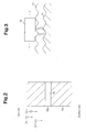
- the section of the outer circumferential surface of the rod 4 corresponding to the lip 15a is subjected to hard chrome plating, thus forming a plating film 17, as illustrated in Fig. 3.
- the plating film 17 is then finished using a grinder 18 such that the surface of the plating film 17 becomes smooth. Accordingly, the surface roughness of the section of the rod 4 becomes relatively low, as compared to the remainder of the rod 4, which is not subjected to the machining.
- the friction between the lip 15a of the oil seal 15 and the outer circumferential surface of the rod 4 is thus prevented from becoming relatively large. As a result, the focal excessive wear of a circumferential portion of the lip 15a is suppressed.
- the non-uniform wear of the lip 15a in the circumferential direction is brought about by the inclination or radial displacement of the rod 4 at the position corresponding to the lip 15a. Therefore, for suppressing such inclination and displacement of the rod 4, a plurality of (in this embodiment, two) adjacent rod guides 5 are arranged parallel in the axial direction of the rod 4, with reference to Fig. 1.
- the rod guides 5 slidably support the outer circumferential surface of the rod 4 and thus guide the reciprocation of the rod 4. This structure suppresses the radial displacement of the rod 4 at the position corresponding to the lip 15a, preventing the non-uniform wear of the lip 15a in the circumferential direction. In other words, the focal excessive wear of a circumferential portion of the lip 15a is suppressed.
- a portion of the rod 4 relatively close to the projecting end of the rod 4 is located relatively close to the portion of the chain pressed by the rod 4.
- the external force acting on the rod 4 in the radial direction thus becomes larger gradually toward the projecting end of the rod 4. This promotes the inclination or radial displacement of the rod 4 at the position relatively close to the projecting end of the rod 4. Therefore, the rod guides 5 are deployed relatively close to the projecting end of the rod 4, with respect to the oil seal 15. In other words, as compared to the oil seal 15, the positions of the rod guides 5 are relatively close to the exterior of the housing 2 in the axial direction of the rod 4.
- the rod guides 5 hold the rod 4 in the radial direction at the position relatively close to the projecting end of the rod 4, with respect to the section of the rod 4 corresponding to the oil seal 15.
- This structure further suppresses the inclination or radial displacement of the rod 4 at the position corresponding to the oil seal 15. The focal excessive wear of a circumferential portion of the lip 15a of the oil seal 15 is thus further reliably suppressed.
- the illustrated embodiment has the following effects.
- the present invention may be applied to a tensioner in which a rod is reciprocated vertically.
- the illustrated embodiment includes the solutions [A] to [C], only one or two of the solutions [A] to [C] may be provided.
- the outer opening 16a of the hole 16 is oriented in the horizontal direction.
- the outer opening 16a of the hole 16 may be faced downward with respect to the horizontal direction, with reference to Figs. 4 and 5, for example.
- the opening 16a of the hole 16 is faced vertically downward, as illustrated in Fig. 5.
- the aforementioned air bleeding structure is formed by selecting the direction along which the opening 16a of the hole 16 is faced.
- the air bleeding structure may be formed by setting the inner diameter of the hole 16.
- the inner diameter of at least one portion of the hole 16 in the extending direction may be reduced sufficiently for prohibiting the used oil from passing through the hole 16.
- This also forms the air bleeding structure that restricts the flow of the used oil from the exterior to the interior of the reservoir 9.
- the hole 16 having the portion with the reduced inner diameter may be originally defined in the outer wall 9a of the reservoir 9.
- an insert with a hole having a portion with a reduced diameter may be fitted in the hole 16.
- the insert may be formed of air permeable material such as a body of crossed metal fibers with a density prohibiting the oil from passing through the fibers or a foam body of urethane resin having continuous foams.
- the air bleeding structure may be formed by selecting the extending direction of the hole 16.
- at least one portion of the hole 16 may extend upward from the exterior of the reservoir 9 to the interior.
- This structure forms the air bleeding structure that prevents the used oil from flowing from the exterior to the interior of the reservoir 9.
- a portion of the hole 16 extends vertically upward, as illustrated in Fig. 8.
- a plurality of portions of the hole 16 in the extending direction may be bent such that the used oil does not enter the interior of the reservoir 9 from the exterior.
- This also forms the aforementioned air bleeding structure. More specifically, one portion of the hole 16 extends upwardly as illustrated in Fig. 8 and two portions of the hole 16 located upstream and downstream from the upwardly extending portion of the hole 16 are defined in a manner bent at 90 degrees. The bleeding air structure is thus formed.
- a plurality of portions of the hole 16 may be bent in a horizontal plane for forming the air bleeding structure.
- a passage may be formed in the reservoir 9 for connecting the interior of the reservoir 9 to the exterior.
- the opening of the passage facing the exterior of the reservoir 9 is connected to a separate water tank.
- the air flowing in the passage is thus passed through the water in the water tank before being discharged to the exterior.
- This structure forms the air bleeding structure that restricts the entrance of the used oil from the exterior of the reservoir 9 to the interior. If the used oil flows to the water tank, the oil does not reach the opening of the passage located at a position corresponding to the water in the tank. The oil is thus reliably prevented from entering the reservoir 9.
- the illustrated embodiment includes the two rod guides 5. However, three or more rod guides 5 may be provided.
- each of the rod guides 5 in the solution [C] is located relatively close to the projected end of the rod 4 with respect to the oil seal 15.
- each rod guide 5 may be disposed relatively close to the retracted end of the rod 4 with respect to the oil seal 15.
- rod guides 5 may be located along the axial direction of the rod 4 with a predetermined clearance defined between adjacent ones of the rod guides 5.
Landscapes
- Engineering & Computer Science (AREA)
- General Engineering & Computer Science (AREA)
- Mechanical Engineering (AREA)
- Devices For Conveying Motion By Means Of Endless Flexible Members (AREA)
- General Details Of Gearings (AREA)
Applications Claiming Priority (2)
| Application Number | Priority Date | Filing Date | Title |
|---|---|---|---|
| JP2003330136A JP4332003B2 (ja) | 2003-09-22 | 2003-09-22 | オイル密閉式チェーンテンショナ |
| JP2003330136 | 2003-09-22 |
Publications (2)
| Publication Number | Publication Date |
|---|---|
| EP1517065A1 true EP1517065A1 (de) | 2005-03-23 |
| EP1517065B1 EP1517065B1 (de) | 2007-06-06 |
Family
ID=34191426
Family Applications (1)
| Application Number | Title | Priority Date | Filing Date |
|---|---|---|---|
| EP04022443A Expired - Lifetime EP1517065B1 (de) | 2003-09-22 | 2004-09-21 | Hydraulische Kettenspannvorrichtung |
Country Status (4)
| Country | Link |
|---|---|
| US (1) | US20050064969A1 (de) |
| EP (1) | EP1517065B1 (de) |
| JP (1) | JP4332003B2 (de) |
| DE (1) | DE602004006810T2 (de) |
Cited By (3)
| Publication number | Priority date | Publication date | Assignee | Title |
|---|---|---|---|---|
| CN109357002A (zh) * | 2018-11-27 | 2019-02-19 | 浙江吉利汽车研究院有限公司 | 一种变速箱润滑系统 |
| DE102016115467B4 (de) * | 2015-09-01 | 2020-03-26 | GM Global Technology Operations LLC | Hydraulische kettenspannvorrichtung mit ölreservoir für invertierte installationen |
| CN112096836A (zh) * | 2020-09-11 | 2020-12-18 | 浙江吉利控股集团有限公司 | 一种通气器装置及具有其的车辆 |
Families Citing this family (9)
| Publication number | Priority date | Publication date | Assignee | Title |
|---|---|---|---|---|
| DE102007028189A1 (de) * | 2007-06-20 | 2008-12-24 | Schaeffler Kg | Hydraulisches Spannelement für einen Zugmitteltrieb |
| JP6494311B2 (ja) * | 2015-02-09 | 2019-04-03 | Ntn株式会社 | 油圧式オートテンショナ |
| DE112016001770T5 (de) * | 2015-05-14 | 2018-01-25 | Borgwarner Inc. | Integriertes scheibenrückschlagventil in einem hydraulikspanner mit dosiertem rücklauf |
| DE102017104533B4 (de) | 2017-03-03 | 2021-11-04 | Volkswagen Aktiengesellschaft | Kettenspanner für eine Kette eines Steuertriebes einer Brennkraftmaschine |
| DE102018114200A1 (de) | 2017-06-15 | 2018-12-20 | Borgwarner Inc. | Spanner mit Rückschlagventil mit steuerbarer Steifigkeit |
| CN111656051B (zh) | 2018-02-26 | 2023-09-29 | 博格华纳公司 | 具有内部储存器技术主孔的可变力张紧器 |
| JP2020101279A (ja) | 2018-12-21 | 2020-07-02 | ボーグワーナー インコーポレーテッド | 内部チェックバルブを含むピストンが備えられたテンショナ |
| EP4162174B1 (de) * | 2020-06-09 | 2025-01-22 | Antony, Ashlyn | Vorrichtung zur beseitigung von spiel und schwingungen in der kette eines kettenantriebs |
| DE112021007054T5 (de) | 2021-04-13 | 2023-12-28 | Borgwarner Inc. | Variable steifigkeitsfunktion durch ein rückschlagventil in einer hydraulischen spannvorrichtung |
Citations (5)
| Publication number | Priority date | Publication date | Assignee | Title |
|---|---|---|---|---|
| DE4340487A1 (de) * | 1992-11-27 | 1994-06-01 | Tsubakimoto Chain Co | Spannvorrichtung |
| US5441457A (en) * | 1993-10-15 | 1995-08-15 | Tsubakimoto Chain Co. | Tensioner having reservoir cover plate |
| US5702317A (en) * | 1995-04-13 | 1997-12-30 | Ntn Corporation | Autotensioner |
| DE10101488A1 (de) * | 2000-01-12 | 2001-08-16 | Tsubakimoto Chain Co | Geschlossene hydraulische Spannvorrichtung |
| US20030139235A1 (en) * | 2000-06-26 | 2003-07-24 | Ken Yamamoto | Chain tensioner |
Family Cites Families (8)
| Publication number | Priority date | Publication date | Assignee | Title |
|---|---|---|---|---|
| DE3145115C2 (de) * | 1981-11-13 | 1983-12-08 | Dr.Ing.H.C. F. Porsche Ag, 7000 Stuttgart | "Hydraulischer Kettenspanner" |
| JPH07110056A (ja) * | 1993-10-14 | 1995-04-25 | Aisin Seiki Co Ltd | オートテンショナ |
| JP3054068B2 (ja) * | 1995-10-27 | 2000-06-19 | 株式会社椿本チエイン | 油圧式テンショナ装置 |
| JP3722909B2 (ja) * | 1996-05-10 | 2005-11-30 | ボルグワーナー・モールステック・ジャパン株式会社 | 油圧テンショナ |
| US5967921A (en) * | 1997-10-09 | 1999-10-19 | Borg-Warner Automotive, Inc. | Hydraulic chain tensioner with molded plastic body |
| JP4392930B2 (ja) * | 2000-01-12 | 2010-01-06 | 株式会社椿本チエイン | 油密封式テンショナ |
| US6395109B1 (en) * | 2000-02-15 | 2002-05-28 | Cargill, Incorporated | Bar product, cylinder rods, hydraulic cylinders, and method for manufacturing |
| JP3805762B2 (ja) * | 2003-07-14 | 2006-08-09 | 株式会社椿本チエイン | 油圧式テンショナ |
-
2003
- 2003-09-22 JP JP2003330136A patent/JP4332003B2/ja not_active Expired - Fee Related
-
2004
- 2004-09-21 EP EP04022443A patent/EP1517065B1/de not_active Expired - Lifetime
- 2004-09-21 DE DE602004006810T patent/DE602004006810T2/de not_active Expired - Lifetime
- 2004-09-22 US US10/945,962 patent/US20050064969A1/en not_active Abandoned
Patent Citations (5)
| Publication number | Priority date | Publication date | Assignee | Title |
|---|---|---|---|---|
| DE4340487A1 (de) * | 1992-11-27 | 1994-06-01 | Tsubakimoto Chain Co | Spannvorrichtung |
| US5441457A (en) * | 1993-10-15 | 1995-08-15 | Tsubakimoto Chain Co. | Tensioner having reservoir cover plate |
| US5702317A (en) * | 1995-04-13 | 1997-12-30 | Ntn Corporation | Autotensioner |
| DE10101488A1 (de) * | 2000-01-12 | 2001-08-16 | Tsubakimoto Chain Co | Geschlossene hydraulische Spannvorrichtung |
| US20030139235A1 (en) * | 2000-06-26 | 2003-07-24 | Ken Yamamoto | Chain tensioner |
Cited By (3)
| Publication number | Priority date | Publication date | Assignee | Title |
|---|---|---|---|---|
| DE102016115467B4 (de) * | 2015-09-01 | 2020-03-26 | GM Global Technology Operations LLC | Hydraulische kettenspannvorrichtung mit ölreservoir für invertierte installationen |
| CN109357002A (zh) * | 2018-11-27 | 2019-02-19 | 浙江吉利汽车研究院有限公司 | 一种变速箱润滑系统 |
| CN112096836A (zh) * | 2020-09-11 | 2020-12-18 | 浙江吉利控股集团有限公司 | 一种通气器装置及具有其的车辆 |
Also Published As
| Publication number | Publication date |
|---|---|
| DE602004006810D1 (de) | 2007-07-19 |
| JP2005098321A (ja) | 2005-04-14 |
| JP4332003B2 (ja) | 2009-09-16 |
| DE602004006810T2 (de) | 2008-01-31 |
| US20050064969A1 (en) | 2005-03-24 |
| EP1517065B1 (de) | 2007-06-06 |
Similar Documents
| Publication | Publication Date | Title |
|---|---|---|
| EP1517065A1 (de) | Hydraulische Kettenspannvorrichtung | |
| WO2012144402A1 (ja) | 油圧式オートテンショナ | |
| JP2017089842A (ja) | チェーンテンショナ | |
| KR102054151B1 (ko) | 텐셔너 | |
| KR20170057130A (ko) | 체인 텐셔너 | |
| JP2895789B2 (ja) | 油圧式テンショナ | |
| KR20180121374A (ko) | 체인 텐셔너 | |
| US5310385A (en) | Oil-operated tensioner with oil-sealed air entrance | |
| US20070287562A1 (en) | Hydraulic Tensioner For A Traction Mechanism Of An Internal Combustion Engine | |
| EP1710472A1 (de) | Automatische spannvorrichtung für zubehör | |
| JP2000213608A (ja) | フリ―ピストン型オ―トテンショナ | |
| JP2010276152A (ja) | オートテンショナ | |
| JP7290436B2 (ja) | チェーンテンショナ | |
| JP6933766B1 (ja) | チェーンテンショナ | |
| WO2015115555A1 (ja) | 油圧式オートテンショナ | |
| JP2019173776A (ja) | 油圧式オートテンショナ | |
| JP2007218401A (ja) | 油圧式オートテンショナ | |
| JP2007032678A (ja) | 油圧式オートテンショナ | |
| JP2009162378A (ja) | オートテンショナ | |
| JP3604070B2 (ja) | 調圧弁 | |
| JP2022138953A (ja) | チェーンテンショナ | |
| JP7651325B2 (ja) | チェーンテンショナ | |
| JP2018155326A (ja) | 油圧式オートテンショナ | |
| JP2009047220A (ja) | オートテンショナ | |
| JP2009024715A (ja) | オートテンショナ |
Legal Events
| Date | Code | Title | Description |
|---|---|---|---|
| PUAI | Public reference made under article 153(3) epc to a published international application that has entered the european phase |
Free format text: ORIGINAL CODE: 0009012 |
|
| 17P | Request for examination filed |
Effective date: 20040921 |
|
| AK | Designated contracting states |
Kind code of ref document: A1 Designated state(s): AT BE BG CH CY CZ DE DK EE ES FI FR GB GR HU IE IT LI LU MC NL PL PT RO SE SI SK TR |
|
| AX | Request for extension of the european patent |
Extension state: AL HR LT LV MK |
|
| AKX | Designation fees paid |
Designated state(s): DE FR GB |
|
| 17Q | First examination report despatched |
Effective date: 20050729 |
|
| GRAP | Despatch of communication of intention to grant a patent |
Free format text: ORIGINAL CODE: EPIDOSNIGR1 |
|
| GRAS | Grant fee paid |
Free format text: ORIGINAL CODE: EPIDOSNIGR3 |
|
| GRAA | (expected) grant |
Free format text: ORIGINAL CODE: 0009210 |
|
| AK | Designated contracting states |
Kind code of ref document: B1 Designated state(s): DE FR GB |
|
| REG | Reference to a national code |
Ref country code: GB Ref legal event code: FG4D |
|
| REF | Corresponds to: |
Ref document number: 602004006810 Country of ref document: DE Date of ref document: 20070719 Kind code of ref document: P |
|
| ET | Fr: translation filed | ||
| PLBE | No opposition filed within time limit |
Free format text: ORIGINAL CODE: 0009261 |
|
| STAA | Information on the status of an ep patent application or granted ep patent |
Free format text: STATUS: NO OPPOSITION FILED WITHIN TIME LIMIT |
|
| 26N | No opposition filed |
Effective date: 20080307 |
|
| PGFP | Annual fee paid to national office [announced via postgrant information from national office to epo] |
Ref country code: GB Payment date: 20090916 Year of fee payment: 6 |
|
| PGFP | Annual fee paid to national office [announced via postgrant information from national office to epo] |
Ref country code: FR Payment date: 20091012 Year of fee payment: 6 |
|
| GBPC | Gb: european patent ceased through non-payment of renewal fee |
Effective date: 20100921 |
|
| REG | Reference to a national code |
Ref country code: FR Ref legal event code: ST Effective date: 20110531 |
|
| PG25 | Lapsed in a contracting state [announced via postgrant information from national office to epo] |
Ref country code: FR Free format text: LAPSE BECAUSE OF NON-PAYMENT OF DUE FEES Effective date: 20100930 |
|
| PG25 | Lapsed in a contracting state [announced via postgrant information from national office to epo] |
Ref country code: GB Free format text: LAPSE BECAUSE OF NON-PAYMENT OF DUE FEES Effective date: 20100921 |
|
| PGFP | Annual fee paid to national office [announced via postgrant information from national office to epo] |
Ref country code: DE Payment date: 20130918 Year of fee payment: 10 |
|
| REG | Reference to a national code |
Ref country code: DE Ref legal event code: R119 Ref document number: 602004006810 Country of ref document: DE |
|
| REG | Reference to a national code |
Ref country code: DE Ref legal event code: R119 Ref document number: 602004006810 Country of ref document: DE Effective date: 20150401 |
|
| PG25 | Lapsed in a contracting state [announced via postgrant information from national office to epo] |
Ref country code: DE Free format text: LAPSE BECAUSE OF NON-PAYMENT OF DUE FEES Effective date: 20150401 |