EP1516522A2 - Verfahren und Vorrichtung zur Ermittlung der Überkehrerntegutmenge - Google Patents
Verfahren und Vorrichtung zur Ermittlung der Überkehrerntegutmenge Download PDFInfo
- Publication number
- EP1516522A2 EP1516522A2 EP04019760A EP04019760A EP1516522A2 EP 1516522 A2 EP1516522 A2 EP 1516522A2 EP 04019760 A EP04019760 A EP 04019760A EP 04019760 A EP04019760 A EP 04019760A EP 1516522 A2 EP1516522 A2 EP 1516522A2
- Authority
- EP
- European Patent Office
- Prior art keywords
- grain
- tailings
- determining
- evaluation
- display unit
- Prior art date
- Legal status (The legal status is an assumption and is not a legal conclusion. Google has not performed a legal analysis and makes no representation as to the accuracy of the status listed.)
- Granted
Links
Images


Classifications
-
- A—HUMAN NECESSITIES
- A01—AGRICULTURE; FORESTRY; ANIMAL HUSBANDRY; HUNTING; TRAPPING; FISHING
- A01D—HARVESTING; MOWING
- A01D41/00—Combines, i.e. harvesters or mowers combined with threshing devices
- A01D41/12—Details of combines
- A01D41/127—Control or measuring arrangements specially adapted for combines
- A01D41/1276—Control or measuring arrangements specially adapted for combines for cleaning mechanisms
-
- A—HUMAN NECESSITIES
- A01—AGRICULTURE; FORESTRY; ANIMAL HUSBANDRY; HUNTING; TRAPPING; FISHING
- A01F—PROCESSING OF HARVESTED PRODUCE; HAY OR STRAW PRESSES; DEVICES FOR STORING AGRICULTURAL OR HORTICULTURAL PRODUCE
- A01F12/00—Parts or details of threshing apparatus
- A01F12/52—Arrangements for returning unthreshed grain to the threshing device
Definitions
- the invention relates to a method and a device for determining the remindling of claims 1 and 13.
- From DE 199 12 372 C1 is a device for measuring at least one part the grains have become known in a tailings.
- On the way of the one of Cleaning device deposited Matterrackerntegutmenge to another Processing device is an exclusively counting the grains sensor arranged. Seen in the conveying direction of the tailings, located in front of the sensor a cornucopia in a housing. The housing is in the direction of the sensor pointing area equipped with customizable openings through which the grains pass.
- the signals generated by the sensor are displayed on a display in the driver's cab visible to the driver.
- the disadvantage of this design is that the measured values for the number of grains as Absolute values are displayed. The measured values shown are missing the reference For example, for throughput or other flow rates in the Cleaning device.
- the invention is therefore the object of a method and an apparatus to further develop the quantity of tailings so that the Crop volume in the tailings in a simple way relatively accurately determined and indicating meaningful.
- the Composition of the crop quantity to be displayed By reducing the crop volume of the tailings by generating Grain current signals and Gutstromsignalen is displayed, the Composition of the crop quantity to be displayed. Based on Composition of the crop quantity allows the driver the effect of Assess cleaning equipment.
- the grain stream signals are detected by a grain flow meter generated, which comprises at least one pulse density sensor, so that the grains contained in the crop flow of the tailings are detected without the Separate grains from non-grain ingredients beforehand.
- the pulse density sensor for measuring the number of grains one Stake sensor is, the crop flow in the combine is not disturbed and the Pulse density reaches a usable level for further processing.
- the rod sensor is fitted with a spring rubber element on the collecting and guiding floor the Kochledge adopted attached so that vibrations z. B. while driving attenuated transferred to the rod sensor. Strong undamped Vibrations can otherwise cause the rod sensor to vibrate, which causes it causes grain signals to be triggered without the grain on the wand sensor incident.
- the good-current signal is advantageously from a volumetric flow meter generated that measures a tailing volume flow in a ear elevator so that those composed of grains and non-grain components Amount of waste can be continuously measured.
- the system of the invention also has a Volume flow measuring device, which has a harvested total amount of grain generating grain current signal generated.
- the grain stream signals and the good current signal to an evaluation and Display unit transmitted.
- the evaluation and display unit determines from this the turnover grain amount and the tailings crop quantity also one Crop grain quantity that represents the amount of harvested grain.
- a Thousand grain mass of the crop and an area equivalent of sensor area and usable separation surface of the overpass device a return grain mass, For example, this grain size in relation to the mass of Sweeping crop quantity will be set.
- the value of the mass ratio is called percentage value is displayed on a display and is used to assess the effect the cleaning device.
- the volume ratio can also be considered percentage value can be displayed on a display and thus serves the Assessment of the effect of the cleaning device.
- the driver sees the one hand Absolute values as well as the ratio of the absolute values to each other.
- the driver has In this display the possibility to recognize, if for example the good flows in reach the maximum permissible volume flows for the elevators.
- the return grain amount and the Reverse crop quantity displayed qualitatively on a display on the screen.
- the evaluation and display unit has already linked the signals with each other, whereby the driver is relieved of this task.
- a high quality tailings generating signal Sweep sensor results when the Kocherieerntegutmenge at least partially in a cleaning device associated with the combine harvester or a portion of the cleaning device is detected, since in this area the influence of the measured values of falsifying events is still small.
- a structurally particularly simple design for determining the grain fraction in the amount of tailings will be calculated if at least one Granule measuring device is provided in the field of cleaning device, which generates grain current signals by means of so-called pulse density sensors, the in an evaluation and display unit qualitatively and / or quantitatively the grain content in the tailings crop quantity represents.
- each level sieve at least one Granule meter be assigned. This has the advantage of being more individual can be reacted to the deposition characteristics of the individual sieve levels by making different settings for the sieves of the different sieve levels be provided.
- the grain flow signals of several Körnerstrommess Nurn in the evaluation and display unit to calculated and displayed, so that the operator more detailed information about the separation characteristics of the individual sieve levels receives.
- FIG. 1 The embodiment of the invention shown in FIG. 1 is a self-propelled combine harvester 1 with a so-called. Tangentialdrehisk 8 and a downstream Horden oftenler 25 as a separator. Below the Horden oftenlers 25 is a cleaning device 18, consisting of two stages arranged one above the other sieves 31, 32 and a blower 33. Die
- the invention is expressly not applicable to such types of combine harvesters limited.
- the operation of such a combine harvester 1 will be described below.
- the Crop 3 is first picked up by a cutting unit 2, which is the crop 3 a feeder 6 supplies.
- the inclined conveyor 6 passes the crop 3 in its rear area to the threshing 9, 10, 11th
- a pre-acceleration drum 9 At the entrance of the threshing unit 8 is a pre-acceleration drum 9, which is downstream of a threshing cylinder 10 in Guthnecardi. Become bottom side the pre-acceleration drum 9 and the threshing drum 10 at least partially surrounded by a concave 11.
- the emerging from the feeder 6 crop 3 is determined by the Vorbevantertrommel 9 detected and further from the threshing drum 10 through the formed between the threshing cylinder 10 and the concave 11 Dreschspalt 13 pulled.
- the threshing cylinder 10 processes the crop mechanically in the result of a grain-chaff mixture 14 deposited on the concave 11 and is supplied via a preparation tray 17 of the cleaning device 18 to the grains 19 of the non-grain components, d. H. from Halm 20 - and spreader parts 21, to separate.
- the material stream 22 consisting essentially of threshed straws then passes over the counterclockwise rotating turning drum 24 onto the tray shaker 25, which conveys the material flow 22 into the rear region of the combine harvester 1.
- the grains 19, which are still in the flow 22, and possibly short straw 20 and chaff 21 are separated by passing through the tray shakers 25 provided with sieve openings 26 onto a return bottom 28.
- the return tray 28 transports grains 19, short straw 20 and chaff 21 to the preparation floor 17.
- the grains 19, the short straw 20 and the chaff 21 likewise pass via the preparation floor 17 into the cleaning device 18, in which the grains 19 are separated from the short straw 20 and the chaff 21.
- the upper wire 31 is usually designed so that it has larger mesh sizes in its rear region, the so-called return region 36.
- the sieve passage 37 together with the screen overflow 38 will be referred to as so-called fürerieerntegutmenge 39 referred.
- the fürerieerntegutmenge 39 is noticeable a sloping collecting tray 40 below the cleaning device 18th and slides in a ear conveyor screw 41.
- the ear conveyor screw 41 promotes the remindsuberntegutmenge 39 in a ⁇ hrenelevator 43, they again the Threshing 8 feeds.
- the collecting tray 40, the ear conveyor screw 41 and the Earthen conveyor 43 together form an overpass 46.
- Ear elevator 43 is a per se known volume flow meter 42 arranged, which consists essentially of a light barrier 44, the one Gutstromsignal Z generated, which depends on the subsidized Swept volume flow 45 of tailings scrap quantity 39 changes and thus a measure for the tailings crop quantity 39.
- the a plurality of pulse density sensors 50 includes (see enlarged section shown B).
- the pulse density sensors 50 are known and therefore bar sensors 51, which are not explained in more detail.
- the bar sensors 51 generate a Grain current signal Y, which is proportional to the number of detected grains 35 in the Sweep lot 39 changes.
- Each rod sensor 49 is with a Federgummielement 48 secured to the collecting tray 56 of the overpass 46.
- the screen overflow 52 which does not fall through the top wire 31, is in the rear Issued area of the combine 1, wherein in this screen overflow 52 contained grains constitute the cleaning loss 53.
- the cleaning loss 53 is detected in a conventional manner with knock sensors 61. That of the Knock sensors 61 generated cleaning loss signal V is substantially proportional to the cleaning losses 53.
- the separation loss 57 is in itself known manner with knock sensors 62 detected. That of the knock sensors 62 generated deposition loss signal A is substantially proportional to the Abscheidegrassen 57.
- Cornelevator 59 is a per se known volume flow meter 65 arranged, which consists essentially of a light barrier arrangement 66, the measures the volume of grain flow 67 conveyed.
- the at least one Photocell arrangement 66 generates a good current signal Z that is proportional to the grain volume 67 changes. It is within the scope of the invention that the Improvement of the good current signals Z and a plurality of light barriers 66 are provided could be.
- the volume flow measuring devices 42, 65 and the Körnerstrommess recognizeden 49 and the knock sensors 61, 62 are connected to an evaluation and display unit 68 which is preferably arranged in the driver's cab 79.
- the good current signals X, Z generated by the light barriers 44, 66 and the grain current signals Y generated by the rod sensors 51 and the Abscheide Albanysignale A and the cleaning loss signals V are transferred to the evaluation and display unit 68.
- the evaluation and display unit 68 calculates with the crop flow signals X, Z the total harvested grain quantity and the tailings crop quantity 39, with the grain flow signal Y the return grain fraction 35 and with the separation loss signals A and the cleaning loss signals V the cleaning losses 53 and the deposition losses 57.
- the from the rod sensors 51 determined number of grains is converted by the evaluation and display unit 68 in a conventional manner with an area equivalent of sensor surface and usable Abscheide Chemistry in an actual number of grains, the area equivalent is stored in the evaluation and display unit 68.
- the evaluation and display unit 68 can also use the calculated number of grains and the thousand-grain mass of the respective crop to calculate the corresponding grain mass or, with the specific gravity of the grains, the grain volume.
- the evaluation and display unit 68 calculates mass and / or volume ratios between crop flow quantities or grain quantities.
- the calculated values are displayed on a screen 69 of the evaluation and display unit 68, whereby the tailings scrap quantity 39 is represented by the generation of grain flow signals Y and good flow signals Z, X.
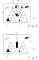
- FIG. 2 shows a first embodiment of a screen 69 of the evaluation and Display unit 68.
- the screen 69 includes a plurality of displays 70-73 that provide information to the driver about machine settings and operating conditions of the combine 1 for Make available.
- a middle triangular graphics display 70 is the in ⁇ hrenelevator 43 currently funded tailings volume flow 45, which is the Amount of waste material 39 corresponds quantitatively.
- the leg of the triangular display is a trapezoidal graphic display 71 arranged at the same time the measured at this moment transfer grain proportion 35 in the tailings crop quantity 39 shown quantitatively.
- two further triangular shaped graphic displays 72, 73 are arranged, wherein the left display 72 the Abscheidegrass 57 and the right display 73 the Cleaning loss 53 reflects.
- Symbols 74-77 are arranged, which symbolize the displayed parameters.
- FIG 3 shows a second embodiment of a screen 69 of the evaluation and Display unit 68.
- the screen 69 differs in that between the both outer graphics displays 72, 73 only a rectangular graphics display 78 is arranged.
- the rectangular graphics display 78 shows the current one percentage ratio between the mass of the transfer grain 35 to the mass the tailings crop 39. The ratio of these two mass flows is an indicator of the effectiveness of the cleaning device 18 and serves as a substitute for the optical, subjective detection of MatterLiteerntegutmenge 39 from the driver.
- the driver can immediately see from the combined displays 70 - 73, 78 how For example, a change in the speed of the blower 33 of the Cleaning device 18 or an adjustment of the mesh size of the sieves 31, 32nd on the cleaning effect of the cleaning device 18. At the change of a parameter, the driver can understand the influence of the adjustment recognize and optimize the effect of the cleaning device 18.
- the combine harvester shown in the figures and the measuring device and the concrete method explained in connection therewith are merely exemplary embodiments which can be varied in many respects by the person skilled in the art without the scope of the invention leave.
- the mass flow of the grains in the tailings can be set in relation to other detected mass flows and the proportioned mass flows can be displayed on a display.
- the ratios shown serve to control the effectiveness of the working organs.
- the indicated masses, quantities and volumes are equivalent to the mass, volume and volume flows determined by the sensors in a limited time interval.
Landscapes
- Life Sciences & Earth Sciences (AREA)
- Environmental Sciences (AREA)
- Threshing Machine Elements (AREA)
- Measuring Volume Flow (AREA)
- Adjustment And Processing Of Grains (AREA)
- Investigating Materials By The Use Of Optical Means Adapted For Particular Applications (AREA)
- Combined Means For Separation Of Solids (AREA)
Abstract
Description
- Fig.1 1
- einen schematischen Querschnitt durch einen Mähdrescher mit einer erfindungsgemäßen Messvorrichtung,
- Fig.2
- einen Bildschirm der Auswerte- und Anzeigeeinheit,
- Fig.3
- eine zweite Ausführung eines Bildschirms der Auswerte- und Anzeigeeinheit
- Fig. 4
- eine Einzelheit nach Fig. 1 mit erfindungsgemäßen Messvorrichtungen
Die Körner 19, das Kurzstroh 20 und die Spreu 21 gelangen schließlich ebenfalls über den Vorbereitungsboden 17 in die Reinigungseinrichtung 18, in welcher die Körner 19 vom Kurzstroh 20 und Spreu 21 getrennt werden. Dies erfolgt in der Weise, dass durch die Sieböffnungen 29, 30 im Obersieb 31 und im Untersieb 32 mittels des Gebläses 33 ein Luftsrom hindurchgefördert wird, welcher das über die Siebe 31, 32 in den hinteren Bereich des Mähdreschers 1 geführte Erntegut 34 auflockert und für das Heraustrennen der spezifisch leichteren Spreu- und Kurzstrohanteile 20, 21 sorgt, während die schweren Erntegutkörner 19 durch die Sieböffnungen 29, 30 fallen. Die Siebe 31, 32 sind teilweise übereinander angeordnet, so dass das Erntegut in zwei Stufen unterschiedlich fein gesiebt wird, wobei die Maschenweite der Siebe 31, 32 änderbar ist. Durch die Veränderung der Maschenweite und /oder der Drehzahl des Gebläses 33 lassen sich der Anteil und die Zusammensetzung der Erntegutmenge, die durch die Sieböffnungen 29, 30 hindurchtritt, der sogenannte Siebdurchgang 37 und der Anteil der über das Sieb 31, 32 transportiert wird, der sogenannte Siebüberlauf 38 beeinflussen. Zudem ist das Obersieb 31 in der Regel so ausgeführt, dass es in seinem rückwärtigen Bereich, dem sogenannten Überkehrbereich 36, größere Maschenweiten aufweist.
Die Auswerte- und Anzeigeeinheit 68 kann weiterhin mit der berechneten Anzahl der Körner und der Tausendkornmasse der jeweiligen Fruchtart die entsprechende Körnermasse oder aber mit der spezifischen Dichte der Körner das Körnervolumen berechnen. Zusätzlich besteht die Möglichkeit, dass die Auswerte- und Anzeigeeinheit 68 Massen- und/oder Volumenverhältnisse zwischen Gutstrommengen bzw. Körnermengen berechnet. Die berechneten Werte werden auf einem Bildschirm 69 der Auswerte- und Anzeigeeinheit 68 angezeigt, wobei die Überkehrerntegutmenge 39 durch die Generierung von Körnerstromsignalen Y und Gutstromsignalen Z, X dargestellt wird.
Die angezeigten Massen, Mengen und Volumen sind äquivalent zu den von den Sensoren in einem begrenzten Zeitintervall ermittelten Massen-, Mengen- und Volumenströmen.
- 1
- Mähdrescher
- 2
- Schneidwerk
- 3
- Erntegut
- 6
- Schrägförderer
- 8
- Dreschwerk
- 9
- Vorbeschleunigertrommel
- 10
- Dreschtrommel
- 11
- Dreschkorb
- 13
- Dreschspalt
- 14
- Korn-Spreu-Gemisch
- 17
- Vorbereitungsboden
- 18
- Reinigungseinrichtung
- 19
- Körner
- 20
- Halmteile/ Kurzstroh
- 21
- Spreuteile/ Spreu
- 22
- Gutstrom
- 24
- Wendetrommel
- 25
- Hordenschüttler
- 26
- Sieböffnungen
- 28
- Rücklaufboden
- 29
- Sieböffnungen Obersieb
- 30
- Sieböffnungen Untersieb
- 31
- Obersieb
- 32
- Untersieb
- 33
- Gebläse
- 34
- Erntegut
- 35
- Überkehrkornanteil
- 36
- Überkehrbereich
- 37
- Siebdurchgang
- 38
- Siebüberlauf
- 39
- Überkehrerntegutmenge
- 40
- Auffangboden
- 41
- Ährenförderschnecke
- 42
- Volumenstrommesseinrichtung
- 43
- Ährenelevator
- 44
- Lichtschranke
- 45
- Überkehrvolumenstrom
- 46
- Überkehreinrichtung
- 47
- Austrittbereich
- 48
- Federgummielement
- 49
- Körnerstrommesseinrichtung
- 50
- Impulsdichtesensor
- 51
- Stabsensor
- 52
- Siebüberlauf
- 53
- Reinigungsverlust
- 54
- Stroh
- 55
- Verlustkörner
- 56
- Auffang- u. Führungsboden
- 57
- Abscheideverlust
- 58
- Kornförderschnecke
- 59
- Kornelevator
- 60
- Korntank
- 61
- Klopfsensoren
- 62
- Klopfsensoren
- 63
- Korntankentleerrohr
- 65
- Volumenstrommesseinrichtung
- 66
- Lichtschrankenanordnung
- 67
- Körnervolumenstrom
- 68
- Auswerte- u. Anzeigeeinheit
- 69
- Bildschirm
- 70
- Graphikanzeige
- 71
- Graphikanzeige
- 72
- Graphikanzeige
- 73
- Graphikanzeige
- 74
- Symbol
- 75
- Symbol
- 76
- Symbol
- 77
- Symbol
- 78
- Graphikanzeige
- 79
- Fahrerkabine
- A
- Abscheideverlustsignal
- V
- Reinigungsverlustsignal
- X
- Körnerstromsignal
- Y
- Körnerstromsignal
- Z
- Gutstromsignal
Claims (18)
- Verfahren zur Ermittlung einer Überkehrerntegutmenge (39) in einer Überkehreinrichtung (46) eines Mähdreschers (1) und wobei die Überkehrerntegutmenge (39) zumindest von Körnern (35) und Nichtkornbestandteilen gebildet wird,
dadurch gekennzeichnet, dass die Überkehrerntegutmenge (39) durch die Generierung von Körnerstromsignalen (Y) und Gutstromsignalen (Z) dargestellt wird. - Verfahren zur Ermittlung einer Überkehrerntegutmenge nach Anspruch 1,
dadurch gekennzeichnet, dass die Körnerstromsignale (Y) mit einer Körnerstrommesseinrichtung (49) generiert werden, die wenigstens einen Impulsdichtesensor (50) umfasst. - Verfahren zur Ermittlung einer Überkehrerntegutmenge nach einem der vorangegangenen Ansprüche,
dadurch gekennzeichnet, dass der Impulsdichtesensor (50) zur Messung des Überkehrkornanteils (35) ein Stabsensor (51) ist. - Verfahren zur Ermittlung einer Überkehrerntegutmenge nach einem der vorangegangenen Ansprüche,
dadurch gekennzeichnet, dass eine Vielzahl von Stabsensoren (51) im Austrittsbereich (47) der Überkehrerntegutmenge (39) aus einer Reinigungsvorrichtung (18) angeordnet sind. - Verfahren zur Ermittlung einer Überkehrerntegutmenge nach einem der vorangegangenen Ansprüche,
dadurch gekennzeichnet, dass der oder die Stabsensoren (51) an einem Auffang- und Führungsboden (56) der Überkehreinrichtung (46) mit einem Federgummielement (48) befestigt sind. - Verfahren zur Ermittlung einer Überkehrerntegutmenge nach einem der vorangegangenen Ansprüche,
dadurch gekennzeichnet, dass das Gutstromsignal (Z) von einer Volumenstrommesseinrichtung (42) generiert wird, die den Volumenstrom der Überkehrerntegutmenge (39) in dem Ährenelevator (43) der Überkehreinrichtung (36) misst. - Verfahren zur Ermittlung einer Überkehrerntegutmenge nach wenigstens einem der vorangegangenen Ansprüche,
dadurch gekennzeichnet, dass dem Körnerelevator (59) eine ein Körnerstromsignal (X) generierende Volumenstrommesseinrichtung (42) zugeordnet ist. - Verfahren zur Ermittlung einer Überkehrerntegutmenge nach einem der vorangegangenen Ansprüche,
dadurch gekennzeichnet, dass die Körnerstromsignale (X, Y) und das Gutstromsignal (Z) an eine Auswerte- und Anzeigeeinheit (68) übermittelt werden, wobei die Auswerteund Anzeigeeinheit (68) aus dem wenigstens einen Körnerstromsignal (Y) des Überkehrbereiches (36) eine Überkehrkornmenge (k), aus dem in einem Körnerelevator (59) generierten Körnerstromsignal (X) eine Erntegutkornmenge (k1) und aus dem Gutstromsignal (Z) eine Überkehrerntegutmenge (39) berechnet. - Verfahren zur Ermittlung einer Überkehrerntegutmenge nach einem der vorangegangenen Ansprüche,
dadurch gekennzeichnet, dass die Auswerte- und Anzeigeeinheit (49 ) aus dem Körnerstromsignal (Y), einer Tausendkornmasse der Fruchtart und einem Flächenäquivalent aus Sensorfläche und nutzbarer Abscheidefläche der Überkehreinrichtung (46) eine Überkehrkornmasse (35) berechnet. - Verfahren zur Ermittlung einer Überkehrerntegutmenge nach einem der vorangegangenen Ansprüche,
dadurch gekennzeichnet, dass die Auswerte- und Anzeigeeinheit (49) aus dem Körnerstromsignal (Y), der Tausendkornmasse der Fruchtart, dem Flächenäquivalent aus Sensorfläche und nutzbarer Abscheidefläche der Überkehreinrichtung (46) und einer spezifischen Dichte ein Überkehrkörnervolumen berechnet. - Verfahren zur Ermittlung einer Überkehrerntegutmenge nach einem der vorangegangenen Ansprüche,
dadurch gekennzeichnet, dass zumindest die Überkehrkornmenge (k) und die Überkehrerntegutmenge (39) zugleich auf getrennten Anzeigen (70, 71) auf einem Bildschirm (69) der Auswerte- und Anzeigeeinheit (68) quantitativ dargestellt werden. - Verfahren zur Ermittlung einer Überkehrerntegutmenge nach einem der vorangegangenen Ansprüche,
dadurch gekennzeichnet, dass zumindest die Überkehrkornmenge (k) und die Überkehrerntegutmenge (39) auf einer Anzeige (78) auf dem Bildschirm (69) qualitativ dargestellt werden. - Vorrichtung zur Ermittlung einer Überkehrerntegutmenge (39) in einer Überkehreinrichtung (46) eines Mähdreschers (1) und wobei die Überkehrerntegutmenge (39) zumindest von Körnern (35) und Nichtkornbestandteilen gebildet wird,
dadurch gekennzeichnet, dass die Überkehrerntegutmenge (39) zumindest teilweise in einer dem Mähdrescher (1) zugeordneten Reinigungseinrichtung (18) oder einem Teilbereich der Reinigungseinrichtung (18) erfasst wird. - Vorrichtung zur Ermittlung einer Überkehrerntegutmenge nach Anspruch 13,
dadurch gekennzeichnet, dass die in der Reinigungseinrichtung (18) oder einem Teilbereich der Reinigungseinrichtung (18) erfasste Überkehrerntegutmenge (39) die Ermittlung des Kornanteils (k1) der Überkehrerntegutmenge (39) umfasst. - Vorrichtung zur Ermittlung einer Überkehrerntegutmenge nach einem der Ansprüche 13 - 14,
dadurch gekennzeichnet, dass der Kornanteil (k1) der Überkehrerntegutmenge (39) mittels zumindest einer Körnerstrommesseinrichtung (49) erfasst wird und wobei die Körnerstrommesseinrichtung (49) zumindest einen Körnerstromsignale (Y) generierenden Impulsdichtesensor (50) aufnimmt, der mit einer Auswerte- und Anzeigeeinheit (68) in Wirkverbindung steht, die eine qualitative und/oder quantitative Anzeige (71) des Kornanteils (k1) der Überkehrerntegutmenge (39) zulässt. - Vorrichtung zur Ermittlung einer Überkehrerntegutmenge nach einem der Ansprüche 13 - 15,
dadurch gekennzeichnet, dass die Reinigungseinrichtung (18) zumindest aus ersten und zweiten Siebebenen (31, 32) besteht und jeder Siebebene (31, 32) zumindest eine Körnerstrommesseinrichtung (49) zugeordnet ist. - Vorrichtung zur Ermittlung einer Überkehrerntegutmenge nach Anspruch 16,
dadurch gekennzeichnet, dass die mehreren Körnerstrommesseinrichtungen (49) Körnerstromsignale (Y) generieren, die in der Auswerte- und Anzeigeeinheit (68) zu siebebenenabhängigen Kornanteilen (k2) der Überkehrerntegutmenge (39) verrechnet und angezeigt werden. - Vorrichtung zur Ermittlung einer Überkehrerntegutmenge nach einem der Ansprüche 13 - 17,
dadurch gekennzeichnet, dass die Auswert- und Anzeigeeinheit (68) verschiedenen Parameter des Erntegutstromes (3) anzeigt und dass diese Parameter, neben dem Überkehrkornanteil (k) und der Überkehrerntegutmenge (39) die Reinigungsverluste (53) und die Abscheideverluste (57) sein können.
Applications Claiming Priority (4)
| Application Number | Priority Date | Filing Date | Title |
|---|---|---|---|
| DE10343916 | 2003-09-19 | ||
| DE10343916 | 2003-09-19 | ||
| DE10358954A DE10358954A1 (de) | 2003-09-19 | 2003-12-15 | Verfahren und Vorrichtung zur Ermittlung der Überkehrerntegutmenge |
| DE10358954 | 2003-12-15 |
Publications (4)
| Publication Number | Publication Date |
|---|---|
| EP1516522A2 true EP1516522A2 (de) | 2005-03-23 |
| EP1516522A3 EP1516522A3 (de) | 2005-04-20 |
| EP1516522B1 EP1516522B1 (de) | 2017-09-20 |
| EP1516522B2 EP1516522B2 (de) | 2023-03-29 |
Family
ID=34195764
Family Applications (1)
| Application Number | Title | Priority Date | Filing Date |
|---|---|---|---|
| EP04019760.0A Expired - Lifetime EP1516522B2 (de) | 2003-09-19 | 2004-08-20 | Verfahren und Vorrichtung zur Ermittlung der Überkehrerntegutmenge |
Country Status (3)
| Country | Link |
|---|---|
| US (2) | US7362233B2 (de) |
| EP (1) | EP1516522B2 (de) |
| RU (1) | RU2350067C2 (de) |
Cited By (11)
| Publication number | Priority date | Publication date | Assignee | Title |
|---|---|---|---|---|
| EP1543712B2 (de) † | 2003-12-19 | 2010-11-24 | CLAAS Selbstfahrende Erntemaschinen GmbH | Verfahren und Vorrichtung zur Regelung von Arbeitsorganen eines Mähdreschers |
| EP2005813B2 (de) † | 2007-06-22 | 2014-11-19 | CLAAS Selbstfahrende Erntemaschinen GmbH | Selbstfahrende landwirtschaftliche Erntemaschine mit Verlustmesseinrichtung |
| CN104756742A (zh) * | 2015-04-24 | 2015-07-08 | 淮安市农业技术推广中心 | 稻麦秸秆持续全量还田下机插秧苗早活棵早分蘖栽培方法 |
| EP2826356B1 (de) | 2013-07-08 | 2017-08-09 | CLAAS Selbstfahrende Erntemaschinen GmbH | Landwirtschaftliche Erntemaschine |
| WO2020252295A1 (en) * | 2019-06-12 | 2020-12-17 | Cnh Industrial America Llc | Apparatus and method for monitoring grain content within a tailings system of an agricultural harvester |
| US11375668B2 (en) * | 2019-01-17 | 2022-07-05 | Agco Do Brasil Sa Ltda | Combine harvester tailings return system |
| DE102022110185A1 (de) | 2022-04-27 | 2023-11-02 | Deere & Company | Verfahren und Anordnung zur Messung einer kornspezifischen Größe an einer Erntemaschine |
| EP4368969A1 (de) | 2022-11-11 | 2024-05-15 | Deere & Company | Verfahren und anordnung zur ermittlung einer massen- und/oder grössenspezifischen grösse von körnerfrüchten |
| EP4454451A1 (de) | 2023-04-25 | 2024-10-30 | Deere & Company | Sensoranordnung für einen mähdrescher |
| EP4544898A1 (de) * | 2023-10-23 | 2025-04-30 | CNH Industrial Belgium N.V. | Verfahren zur kalibrierung eines überkehrsensors in einem mähdrescher |
| EP4702830A1 (de) | 2024-08-29 | 2026-03-04 | Deere & Company | Sensoranordnung zur erfassung von körnern in einem körner und nichtkornbestandteile enthaltenden materialstrom in einem mähdrescher |
Families Citing this family (41)
| Publication number | Priority date | Publication date | Assignee | Title |
|---|---|---|---|---|
| EP1516522B2 (de) * | 2003-09-19 | 2023-03-29 | CLAAS Selbstfahrende Erntemaschinen GmbH | Verfahren und Vorrichtung zur Ermittlung der Überkehrerntegutmenge |
| DE102005026159A1 (de) * | 2005-06-06 | 2007-01-25 | Claas Selbstfahrende Erntemaschinen Gmbh | Verfahren zur Steuerung einer Erntemaschine |
| US7572180B2 (en) * | 2007-02-13 | 2009-08-11 | Cnh America Llc | Distribution leveling for an agricultural combine |
| DE102007046678A1 (de) * | 2007-09-27 | 2009-04-09 | Claas Selbstfahrende Erntemaschinen Gmbh | Landwirtschaftliches Arbeitsfahrzeug |
| DE102008027906A1 (de) * | 2008-06-12 | 2009-12-17 | Claas Selbstfahrende Erntemaschinen Gmbh | Landwirtschaftliche Erntemaschine |
| DE102008057461A1 (de) * | 2008-11-14 | 2010-05-20 | Claas Selbstfahrende Erntemaschinen Gmbh | Anzeigeeinheit |
| US9324197B2 (en) | 2011-03-11 | 2016-04-26 | Intelligent Agricultural Soultions | Method and system for managing the hand-off between control terminals |
| US9631964B2 (en) | 2011-03-11 | 2017-04-25 | Intelligent Agricultural Solutions, Llc | Acoustic material flow sensor |
| US10318138B2 (en) * | 2011-03-11 | 2019-06-11 | Intelligent Agricultural Solutions Llc | Harvesting machine capable of automatic adjustment |
| US9330062B2 (en) | 2011-03-11 | 2016-05-03 | Intelligent Agricultural Solutions, Llc | Vehicle control and gateway module |
| US9629308B2 (en) | 2011-03-11 | 2017-04-25 | Intelligent Agricultural Solutions, Llc | Harvesting machine capable of automatic adjustment |
| US10321624B2 (en) | 2011-03-11 | 2019-06-18 | Intelligent Agriculture Solutions LLC | Air seeder manifold system |
| US9474208B2 (en) * | 2011-11-15 | 2016-10-25 | Appareo Systems, Llc | System and method for determining material yield and/or loss from a harvesting machine using acoustic sensors |
| US8282453B1 (en) * | 2011-05-12 | 2012-10-09 | Cnh America Llc | Tailings distribution control for harvester |
| US9850748B2 (en) | 2012-04-30 | 2017-12-26 | Halliburton Energy Services, Inc. | Propping complex fracture networks in tight formations |
| DE102013106128A1 (de) * | 2012-07-16 | 2014-06-12 | Claas Selbstfahrende Erntemaschinen Gmbh | Landwirtschaftliche Arbeitsmaschine mit zumindest einer Steuerungseinrichtung |
| DE102013106131A1 (de) * | 2012-07-16 | 2014-06-12 | Claas Selbstfahrende Erntemaschinen Gmbh | Fahrerassistenzsystem für landwirtschaftliche Arbeitsmaschine |
| US9078397B2 (en) | 2012-11-16 | 2015-07-14 | Cnh Industrial America Llc | System for conveying agricultural material in a harvester |
| US9345197B2 (en) * | 2013-05-10 | 2016-05-24 | Agco Corporation | Combine harvester with even crop distribution |
| US9699970B2 (en) | 2013-09-19 | 2017-07-11 | Cnh Industrial America Llc | Combine side-shake cleaning control system |
| GB201319215D0 (en) * | 2013-10-31 | 2013-12-18 | Agco As | Grain seperating apparatus in a combine harvester |
| US10085379B2 (en) | 2014-09-12 | 2018-10-02 | Appareo Systems, Llc | Grain quality sensor |
| BE1022414B1 (nl) | 2014-10-14 | 2016-03-24 | Cnh Industrial Belgium Nv | Sensoropstelling voor maaidorser voor het detecteren van het schoongraanverlies |
| US9779330B2 (en) | 2014-12-26 | 2017-10-03 | Deere & Company | Grain quality monitoring |
| CN104737721B (zh) * | 2015-03-04 | 2016-08-31 | 江苏大学 | 一种联合收获机自适应清选控制装置及其自适应清选方法 |
| CN104663227B (zh) * | 2015-03-13 | 2016-02-24 | 淮安市农业技术推广中心 | 苏北地区稻草还田小麦底墒播种全苗壮苗方法 |
| JP6667230B2 (ja) * | 2015-08-31 | 2020-03-18 | 株式会社クボタ | コンバイン |
| US20170112061A1 (en) * | 2015-10-27 | 2017-04-27 | Cnh Industrial America Llc | Graphical yield monitor static (previous) data display on in-cab display |
| JP2017085971A (ja) * | 2015-11-10 | 2017-05-25 | 三菱マヒンドラ農機株式会社 | コンバイン |
| US9999176B2 (en) * | 2016-04-29 | 2018-06-19 | Cnh Industrial America Llc | Optical tailings sensor in tri-sweep tailings housing |
| EP3537868B1 (de) * | 2016-11-10 | 2021-01-06 | CNH Industrial Belgium NV | Geschlossener regelkreis für aggressivität einer spreuverarbeitungsvorrichtung |
| CA2963225C (en) * | 2017-04-05 | 2019-01-08 | Schergain Holdings Ltd. | Grain loss gauging system for combine harvester |
| US10219439B1 (en) * | 2017-08-14 | 2019-03-05 | Cnh Industrial America Llc | Harvester cleaning system with conveyor enhanced cascades |
| US10660268B2 (en) | 2017-12-16 | 2020-05-26 | Deere & Company | Harvester with electromagnetic plane crop material flow sensor |
| US11042280B2 (en) * | 2018-03-05 | 2021-06-22 | Agco Corporation | Harvesting machine with visualization system |
| US11013175B2 (en) * | 2018-07-26 | 2021-05-25 | Deere & Company | Grain loss apparatus for a grain harvesting vehicle |
| EP3714674B1 (de) * | 2019-03-28 | 2023-09-06 | CNH Industrial Belgium NV | Strohschüttlerlastüberwachung |
| RU202395U1 (ru) * | 2020-06-16 | 2021-02-16 | Общество с ограниченной ответственностью "Комбайновый завод "Ростсельмаш" | Устройство контроля потерь зерна за сепаратором грубого вороха |
| IT202100006422A1 (it) * | 2021-03-17 | 2022-09-17 | Cnh Ind Italia Spa | Veicolo da raccolta dotato di sistema autolivellante |
| JP2023175132A (ja) * | 2022-05-30 | 2023-12-12 | ヤンマーホールディングス株式会社 | 収穫機械 |
| CN120609738B (zh) * | 2025-08-11 | 2025-10-14 | 山东大学 | 基于多尺度小波变换的大喂入量籽粒识别方法及系统 |
Family Cites Families (29)
| Publication number | Priority date | Publication date | Assignee | Title |
|---|---|---|---|---|
| SU495052A1 (ru) * | 1971-10-11 | 1975-12-15 | Всесоюзный Ордена Трудового Красного Знамени Научно-Исследовательский Институт Механизации Сельского Хозяйства | Устройство дл определени потерь за молотилкой зерноуборочного комбайна |
| US3939846A (en) * | 1974-06-27 | 1976-02-24 | Vladimir Kirillovich Drozhzhin | Device for monitoring and controlling the relative flows and losses of grain in a grain combine thresher |
| DE2445045A1 (de) * | 1974-09-20 | 1976-04-01 | Fahr Ag Maschf | Maehdrescher |
| US3935866A (en) * | 1974-12-23 | 1976-02-03 | Allis-Chalmers Corporation | Grain loss monitor |
| US4036065A (en) * | 1976-05-11 | 1977-07-19 | Senstek Ltd. | Grain loss monitor |
| US4296409A (en) * | 1979-03-12 | 1981-10-20 | Dickey-John Corporation | Combine performance monitor |
| US4517792A (en) * | 1982-05-07 | 1985-05-21 | Deere & Company | Grain loss monitor sensor mounting arrangement for a combine |
| CA1292369C (en) * | 1987-05-15 | 1991-11-26 | Her Majesty The Queen In Right Of Canada, As Represented By The Ministe | Unthreshed head grain loss monitor |
| EP0339141B1 (de) * | 1988-04-26 | 1994-07-06 | New Holland Belgium N.V. | Verfahren und Vorrichtung zur Körnerverlustmessung an Dreschmaschinen |
| US5046362A (en) * | 1988-04-26 | 1991-09-10 | Ford New Holland, Inc. | Grain loss monitors for harvesting machines |
| DE69024204T2 (de) * | 1990-06-23 | 1996-05-23 | Ford New Holland Nv | Durchflussmessgerät |
| DE4341834C1 (de) * | 1993-12-08 | 1995-04-20 | Claas Ohg | Landmaschine, insbesondere Mähdrescher, mit Multiprozessor-Leitvorrichtung |
| DE4431824C1 (de) * | 1994-09-07 | 1996-05-02 | Claas Ohg | Mähdrescherbetrieb mit Betriebsdatenkataster |
| DE19618042A1 (de) | 1996-05-04 | 1997-11-06 | Same Spa | Anzeige der Überkehrbelastung an Mähdreschern mit Wurfelevatoren |
| US6053811A (en) * | 1996-10-10 | 2000-04-25 | Case Corporation | Tailings monitor for an agricultural combine |
| US6121782A (en) * | 1997-04-09 | 2000-09-19 | Case Corporation | Method for measuring yield and moisture |
| DE19725028A1 (de) * | 1997-06-13 | 1998-12-17 | Claas Selbstfahr Erntemasch | Sensor für Erntemaschinen |
| US6125702A (en) * | 1998-02-12 | 2000-10-03 | Kuchar; George J. | Return grain elevator monitor |
| US6115115A (en) | 1998-06-23 | 2000-09-05 | Deere & Company | Volume sensor for paddle elevator using laser light |
| DE19912372C1 (de) * | 1999-03-19 | 2000-11-09 | Case Harvesting Sys Gmbh | Vorrichtung zur Messung des Kornanteiles in einer Überkehr eines Mähdreschers |
| US6119442A (en) | 1999-05-14 | 2000-09-19 | Case Corporation | Combine setting autoadjust with machine vision |
| GB2356546A (en) * | 1999-11-26 | 2001-05-30 | Ford New Holland Nv | Threshing and separating unit for axial flow combines |
| US6460008B1 (en) * | 2000-07-19 | 2002-10-01 | Ivan E. Hardt | Yield monitoring system for grain harvesting combine |
| US20020107624A1 (en) * | 2001-02-07 | 2002-08-08 | Deere & Company, A Delaware Corporation | Monitoring equipment for an agricultural machine |
| DE10147733A1 (de) * | 2001-09-27 | 2003-04-10 | Claas Selbstfahr Erntemasch | Verfahren und Vorrichtung zur Ermittlung einer Erntemaschineneinstellung |
| US6726559B2 (en) * | 2002-05-14 | 2004-04-27 | Deere & Company | Harvester with control system considering operator feedback |
| CA2436246C (en) * | 2003-07-30 | 2009-03-24 | Deere & Company | Measuring device for measuring harvested crop throughput |
| EP1516522B2 (de) * | 2003-09-19 | 2023-03-29 | CLAAS Selbstfahrende Erntemaschinen GmbH | Verfahren und Vorrichtung zur Ermittlung der Überkehrerntegutmenge |
| US6962526B2 (en) * | 2004-02-23 | 2005-11-08 | Cnh America Llc | Combine tailings sensor system |
-
2004
- 2004-08-20 EP EP04019760.0A patent/EP1516522B2/de not_active Expired - Lifetime
- 2004-08-25 RU RU2004125884/12A patent/RU2350067C2/ru active
- 2004-09-14 US US10/940,437 patent/US7362233B2/en not_active Expired - Lifetime
-
2007
- 2007-03-23 US US11/690,171 patent/US20090233661A9/en not_active Abandoned
Cited By (17)
| Publication number | Priority date | Publication date | Assignee | Title |
|---|---|---|---|---|
| EP1543712B2 (de) † | 2003-12-19 | 2010-11-24 | CLAAS Selbstfahrende Erntemaschinen GmbH | Verfahren und Vorrichtung zur Regelung von Arbeitsorganen eines Mähdreschers |
| EP2005813B2 (de) † | 2007-06-22 | 2014-11-19 | CLAAS Selbstfahrende Erntemaschinen GmbH | Selbstfahrende landwirtschaftliche Erntemaschine mit Verlustmesseinrichtung |
| EP2826356B1 (de) | 2013-07-08 | 2017-08-09 | CLAAS Selbstfahrende Erntemaschinen GmbH | Landwirtschaftliche Erntemaschine |
| CN104756742A (zh) * | 2015-04-24 | 2015-07-08 | 淮安市农业技术推广中心 | 稻麦秸秆持续全量还田下机插秧苗早活棵早分蘖栽培方法 |
| CN104756742B (zh) * | 2015-04-24 | 2016-02-03 | 淮安市农业技术推广中心 | 稻麦秸秆持续全量还田下机插秧苗早活棵早分蘖栽培方法 |
| US11375668B2 (en) * | 2019-01-17 | 2022-07-05 | Agco Do Brasil Sa Ltda | Combine harvester tailings return system |
| WO2020252295A1 (en) * | 2019-06-12 | 2020-12-17 | Cnh Industrial America Llc | Apparatus and method for monitoring grain content within a tailings system of an agricultural harvester |
| US11375662B2 (en) | 2019-06-12 | 2022-07-05 | Cnh Industrial America Llc | Apparatus and method for monitoring grain content within a tailings system of an agricultural harvester |
| DE102022110185A1 (de) | 2022-04-27 | 2023-11-02 | Deere & Company | Verfahren und Anordnung zur Messung einer kornspezifischen Größe an einer Erntemaschine |
| US12610887B2 (en) | 2022-04-27 | 2026-04-28 | Deere & Company | Method, apparatus and system for measuring a grain on a harvesting machine |
| EP4368969A1 (de) | 2022-11-11 | 2024-05-15 | Deere & Company | Verfahren und anordnung zur ermittlung einer massen- und/oder grössenspezifischen grösse von körnerfrüchten |
| DE102022129876A1 (de) | 2022-11-11 | 2024-05-16 | Deere & Company | Verfahren und Anordnung zur Ermittlung einer massen- und/oder größenspezifischen Größe von Körnerfrüchten |
| US12584855B2 (en) | 2022-11-11 | 2026-03-24 | Deere & Company | Method and arrangement for determining a variable of grain crops |
| EP4454451A1 (de) | 2023-04-25 | 2024-10-30 | Deere & Company | Sensoranordnung für einen mähdrescher |
| DE102023110536A1 (de) | 2023-04-25 | 2024-10-31 | Deere & Company | Sensoranordnung für einen Mähdrescher |
| EP4544898A1 (de) * | 2023-10-23 | 2025-04-30 | CNH Industrial Belgium N.V. | Verfahren zur kalibrierung eines überkehrsensors in einem mähdrescher |
| EP4702830A1 (de) | 2024-08-29 | 2026-03-04 | Deere & Company | Sensoranordnung zur erfassung von körnern in einem körner und nichtkornbestandteile enthaltenden materialstrom in einem mähdrescher |
Also Published As
| Publication number | Publication date |
|---|---|
| EP1516522B2 (de) | 2023-03-29 |
| US7362233B2 (en) | 2008-04-22 |
| RU2004125884A (ru) | 2006-02-10 |
| US20090233661A9 (en) | 2009-09-17 |
| RU2350067C2 (ru) | 2009-03-27 |
| EP1516522B1 (de) | 2017-09-20 |
| EP1516522A3 (de) | 2005-04-20 |
| US20070161422A1 (en) | 2007-07-12 |
| US20050143153A1 (en) | 2005-06-30 |
Similar Documents
| Publication | Publication Date | Title |
|---|---|---|
| EP1516522B1 (de) | Verfahren und Vorrichtung zur Ermittlung der Überkehrerntegutmenge | |
| DE3850570T2 (de) | Verfahren und Vorrichtung zur Körnerverlustmessung an Dreschmaschinen. | |
| EP3613272B1 (de) | Mähdrescher | |
| EP2401906B1 (de) | Vorrichtung zur Erfassung und Bestimmung der Zusammensetzung von Schüttgut | |
| EP2057882B2 (de) | Verfahren zur Qualitätsüberwachung von Erntegut | |
| EP1321023B1 (de) | Verfahren zur Verlustbestimmung an landwirtschaftlichen Erntemaschinen | |
| DE19912372C1 (de) | Vorrichtung zur Messung des Kornanteiles in einer Überkehr eines Mähdreschers | |
| EP1763988B1 (de) | Verfahren zur Einstellung eines Arbeitsaggregats einer Erntemaschine | |
| DE60114121T2 (de) | Sensorsystem für Mähdrescher | |
| EP2005813B2 (de) | Selbstfahrende landwirtschaftliche Erntemaschine mit Verlustmesseinrichtung | |
| EP1759574B1 (de) | Vorrichtung und Verfahren zur Detektion von Körperschallschwingungen | |
| DE10147733A1 (de) | Verfahren und Vorrichtung zur Ermittlung einer Erntemaschineneinstellung | |
| DE2106970C3 (de) | Ernte- und/oder Verarbeitungsmaschine für landwirtschaftliches Gut, insbesondere für Mähdrescher | |
| DE102005047335A1 (de) | Selbstfahrende Erntemaschine und Betriebsverfahren dafür | |
| EP1091203A2 (de) | Verfahren zur Erfassung der Partikel eines Tabakpartikel-Stroms | |
| EP2761984A1 (de) | Schwingungsaufnehmereinheit | |
| EP1662247A1 (de) | Verfahren zur Bestimmung der Partikelform und/oder Grösse von landwirtschaftlichen Gutpartikeln | |
| DE3884602T2 (de) | Körnerverlustmonitoren für Mähmaschinen. | |
| EP1900272A1 (de) | Anzeigeeinheit einer landwirtschaftlichen Arbeitsmaschine | |
| DE102021106119A1 (de) | Verfahren zum Betrieb einer Hackfruchtfördermaschine | |
| EP4454451A1 (de) | Sensoranordnung für einen mähdrescher | |
| EP4029364A1 (de) | Landwirtschaftliche erntemaschine mit mitteln zur bestimmung des tausendkorngewichts | |
| EP3459337A1 (de) | Landwirtschaftliche arbeitsmaschine | |
| DE2233711A1 (de) | Verfahren und vorrichtung zur bestimmung der abfallmenge von koernerfruechten einer erntemaschine | |
| DE1632870C3 (de) | Vorrichtung zum Messen von Körnerverlusten in Dreschmaschinen, insbesondere Mähdreschern |
Legal Events
| Date | Code | Title | Description |
|---|---|---|---|
| PUAI | Public reference made under article 153(3) epc to a published international application that has entered the european phase |
Free format text: ORIGINAL CODE: 0009012 |
|
| PUAL | Search report despatched |
Free format text: ORIGINAL CODE: 0009013 |
|
| AK | Designated contracting states |
Kind code of ref document: A2 Designated state(s): AT BE BG CH CY CZ DE DK EE ES FI FR GB GR HU IE IT LI LU MC NL PL PT RO SE SI SK TR |
|
| AX | Request for extension of the european patent |
Extension state: AL HR LT LV MK |
|
| AK | Designated contracting states |
Kind code of ref document: A3 Designated state(s): AT BE BG CH CY CZ DE DK EE ES FI FR GB GR HU IE IT LI LU MC NL PL PT RO SE SI SK TR |
|
| AX | Request for extension of the european patent |
Extension state: AL HR LT LV MK |
|
| 17P | Request for examination filed |
Effective date: 20051020 |
|
| AKX | Designation fees paid |
Designated state(s): AT BE BG CH CY CZ DE DK EE ES FI FR GB GR HU IE IT LI LU MC NL PL PT RO SE SI SK TR |
|
| RAP1 | Party data changed (applicant data changed or rights of an application transferred) |
Owner name: CLAAS SELBSTFAHRENDE ERNTEMASCHINEN GMBH |
|
| GRAP | Despatch of communication of intention to grant a patent |
Free format text: ORIGINAL CODE: EPIDOSNIGR1 |
|
| STAA | Information on the status of an ep patent application or granted ep patent |
Free format text: STATUS: GRANT OF PATENT IS INTENDED |
|
| GRAJ | Information related to disapproval of communication of intention to grant by the applicant or resumption of examination proceedings by the epo deleted |
Free format text: ORIGINAL CODE: EPIDOSDIGR1 |
|
| STAA | Information on the status of an ep patent application or granted ep patent |
Free format text: STATUS: EXAMINATION IS IN PROGRESS |
|
| INTG | Intention to grant announced |
Effective date: 20161206 |
|
| INTC | Intention to grant announced (deleted) | ||
| GRAP | Despatch of communication of intention to grant a patent |
Free format text: ORIGINAL CODE: EPIDOSNIGR1 |
|
| STAA | Information on the status of an ep patent application or granted ep patent |
Free format text: STATUS: GRANT OF PATENT IS INTENDED |
|
| INTG | Intention to grant announced |
Effective date: 20170613 |
|
| GRAS | Grant fee paid |
Free format text: ORIGINAL CODE: EPIDOSNIGR3 |
|
| GRAA | (expected) grant |
Free format text: ORIGINAL CODE: 0009210 |
|
| STAA | Information on the status of an ep patent application or granted ep patent |
Free format text: STATUS: THE PATENT HAS BEEN GRANTED |
|
| AK | Designated contracting states |
Kind code of ref document: B1 Designated state(s): AT BE BG CH CY CZ DE DK EE ES FI FR GB GR HU IE IT LI LU MC NL PL PT RO SE SI SK TR |
|
| REG | Reference to a national code |
Ref country code: GB Ref legal event code: FG4D Free format text: NOT ENGLISH |
|
| REG | Reference to a national code |
Ref country code: CH Ref legal event code: EP |
|
| REG | Reference to a national code |
Ref country code: AT Ref legal event code: REF Ref document number: 929417 Country of ref document: AT Kind code of ref document: T Effective date: 20171015 |
|
| REG | Reference to a national code |
Ref country code: IE Ref legal event code: FG4D Free format text: LANGUAGE OF EP DOCUMENT: GERMAN |
|
| REG | Reference to a national code |
Ref country code: DE Ref legal event code: R096 Ref document number: 502004015590 Country of ref document: DE |
|
| REG | Reference to a national code |
Ref country code: NL Ref legal event code: MP Effective date: 20170920 |
|
| PG25 | Lapsed in a contracting state [announced via postgrant information from national office to epo] |
Ref country code: FI Free format text: LAPSE BECAUSE OF FAILURE TO SUBMIT A TRANSLATION OF THE DESCRIPTION OR TO PAY THE FEE WITHIN THE PRESCRIBED TIME-LIMIT Effective date: 20170920 Ref country code: SE Free format text: LAPSE BECAUSE OF FAILURE TO SUBMIT A TRANSLATION OF THE DESCRIPTION OR TO PAY THE FEE WITHIN THE PRESCRIBED TIME-LIMIT Effective date: 20170920 |
|
| PG25 | Lapsed in a contracting state [announced via postgrant information from national office to epo] |
Ref country code: GR Free format text: LAPSE BECAUSE OF FAILURE TO SUBMIT A TRANSLATION OF THE DESCRIPTION OR TO PAY THE FEE WITHIN THE PRESCRIBED TIME-LIMIT Effective date: 20171221 Ref country code: BG Free format text: LAPSE BECAUSE OF FAILURE TO SUBMIT A TRANSLATION OF THE DESCRIPTION OR TO PAY THE FEE WITHIN THE PRESCRIBED TIME-LIMIT Effective date: 20171220 |
|
| PG25 | Lapsed in a contracting state [announced via postgrant information from national office to epo] |
Ref country code: NL Free format text: LAPSE BECAUSE OF FAILURE TO SUBMIT A TRANSLATION OF THE DESCRIPTION OR TO PAY THE FEE WITHIN THE PRESCRIBED TIME-LIMIT Effective date: 20170920 |
|
| PG25 | Lapsed in a contracting state [announced via postgrant information from national office to epo] |
Ref country code: PL Free format text: LAPSE BECAUSE OF FAILURE TO SUBMIT A TRANSLATION OF THE DESCRIPTION OR TO PAY THE FEE WITHIN THE PRESCRIBED TIME-LIMIT Effective date: 20170920 Ref country code: RO Free format text: LAPSE BECAUSE OF FAILURE TO SUBMIT A TRANSLATION OF THE DESCRIPTION OR TO PAY THE FEE WITHIN THE PRESCRIBED TIME-LIMIT Effective date: 20170920 Ref country code: CZ Free format text: LAPSE BECAUSE OF FAILURE TO SUBMIT A TRANSLATION OF THE DESCRIPTION OR TO PAY THE FEE WITHIN THE PRESCRIBED TIME-LIMIT Effective date: 20170920 Ref country code: ES Free format text: LAPSE BECAUSE OF FAILURE TO SUBMIT A TRANSLATION OF THE DESCRIPTION OR TO PAY THE FEE WITHIN THE PRESCRIBED TIME-LIMIT Effective date: 20170920 |
|
| PG25 | Lapsed in a contracting state [announced via postgrant information from national office to epo] |
Ref country code: SK Free format text: LAPSE BECAUSE OF FAILURE TO SUBMIT A TRANSLATION OF THE DESCRIPTION OR TO PAY THE FEE WITHIN THE PRESCRIBED TIME-LIMIT Effective date: 20170920 Ref country code: EE Free format text: LAPSE BECAUSE OF FAILURE TO SUBMIT A TRANSLATION OF THE DESCRIPTION OR TO PAY THE FEE WITHIN THE PRESCRIBED TIME-LIMIT Effective date: 20170920 |
|
| REG | Reference to a national code |
Ref country code: DE Ref legal event code: R026 Ref document number: 502004015590 Country of ref document: DE |
|
| PLBI | Opposition filed |
Free format text: ORIGINAL CODE: 0009260 |
|
| PLAX | Notice of opposition and request to file observation + time limit sent |
Free format text: ORIGINAL CODE: EPIDOSNOBS2 |
|
| 26 | Opposition filed |
Opponent name: DEERE & COMPANY/JOHN DEERE GMBH & CO. KG Effective date: 20180611 |
|
| PG25 | Lapsed in a contracting state [announced via postgrant information from national office to epo] |
Ref country code: DK Free format text: LAPSE BECAUSE OF FAILURE TO SUBMIT A TRANSLATION OF THE DESCRIPTION OR TO PAY THE FEE WITHIN THE PRESCRIBED TIME-LIMIT Effective date: 20170920 |
|
| REG | Reference to a national code |
Ref country code: FR Ref legal event code: PLFP Year of fee payment: 15 |
|
| PLBB | Reply of patent proprietor to notice(s) of opposition received |
Free format text: ORIGINAL CODE: EPIDOSNOBS3 |
|
| PG25 | Lapsed in a contracting state [announced via postgrant information from national office to epo] |
Ref country code: SI Free format text: LAPSE BECAUSE OF FAILURE TO SUBMIT A TRANSLATION OF THE DESCRIPTION OR TO PAY THE FEE WITHIN THE PRESCRIBED TIME-LIMIT Effective date: 20170920 |
|
| PG25 | Lapsed in a contracting state [announced via postgrant information from national office to epo] |
Ref country code: MC Free format text: LAPSE BECAUSE OF FAILURE TO SUBMIT A TRANSLATION OF THE DESCRIPTION OR TO PAY THE FEE WITHIN THE PRESCRIBED TIME-LIMIT Effective date: 20170920 |
|
| REG | Reference to a national code |
Ref country code: CH Ref legal event code: PL |
|
| GBPC | Gb: european patent ceased through non-payment of renewal fee |
Effective date: 20180820 |
|
| PG25 | Lapsed in a contracting state [announced via postgrant information from national office to epo] |
Ref country code: LU Free format text: LAPSE BECAUSE OF NON-PAYMENT OF DUE FEES Effective date: 20180820 Ref country code: LI Free format text: LAPSE BECAUSE OF NON-PAYMENT OF DUE FEES Effective date: 20180831 Ref country code: CH Free format text: LAPSE BECAUSE OF NON-PAYMENT OF DUE FEES Effective date: 20180831 |
|
| REG | Reference to a national code |
Ref country code: IE Ref legal event code: MM4A |
|
| PG25 | Lapsed in a contracting state [announced via postgrant information from national office to epo] |
Ref country code: IE Free format text: LAPSE BECAUSE OF NON-PAYMENT OF DUE FEES Effective date: 20180820 |
|
| REG | Reference to a national code |
Ref country code: AT Ref legal event code: MM01 Ref document number: 929417 Country of ref document: AT Kind code of ref document: T Effective date: 20180820 |
|
| PG25 | Lapsed in a contracting state [announced via postgrant information from national office to epo] |
Ref country code: GB Free format text: LAPSE BECAUSE OF NON-PAYMENT OF DUE FEES Effective date: 20180820 |
|
| PG25 | Lapsed in a contracting state [announced via postgrant information from national office to epo] |
Ref country code: AT Free format text: LAPSE BECAUSE OF NON-PAYMENT OF DUE FEES Effective date: 20180820 |
|
| PG25 | Lapsed in a contracting state [announced via postgrant information from national office to epo] |
Ref country code: TR Free format text: LAPSE BECAUSE OF FAILURE TO SUBMIT A TRANSLATION OF THE DESCRIPTION OR TO PAY THE FEE WITHIN THE PRESCRIBED TIME-LIMIT Effective date: 20170920 |
|
| PG25 | Lapsed in a contracting state [announced via postgrant information from national office to epo] |
Ref country code: HU Free format text: LAPSE BECAUSE OF FAILURE TO SUBMIT A TRANSLATION OF THE DESCRIPTION OR TO PAY THE FEE WITHIN THE PRESCRIBED TIME-LIMIT; INVALID AB INITIO Effective date: 20040820 Ref country code: PT Free format text: LAPSE BECAUSE OF FAILURE TO SUBMIT A TRANSLATION OF THE DESCRIPTION OR TO PAY THE FEE WITHIN THE PRESCRIBED TIME-LIMIT Effective date: 20170920 |
|
| PG25 | Lapsed in a contracting state [announced via postgrant information from national office to epo] |
Ref country code: CY Free format text: LAPSE BECAUSE OF FAILURE TO SUBMIT A TRANSLATION OF THE DESCRIPTION OR TO PAY THE FEE WITHIN THE PRESCRIBED TIME-LIMIT Effective date: 20170920 |
|
| PUAH | Patent maintained in amended form |
Free format text: ORIGINAL CODE: 0009272 |
|
| STAA | Information on the status of an ep patent application or granted ep patent |
Free format text: STATUS: PATENT MAINTAINED AS AMENDED |
|
| 27A | Patent maintained in amended form |
Effective date: 20230329 |
|
| AK | Designated contracting states |
Kind code of ref document: B2 Designated state(s): AT BE BG CH CY CZ DE DK EE ES FI FR GB GR HU IE IT LI LU MC NL PL PT RO SE SI SK TR |
|
| REG | Reference to a national code |
Ref country code: DE Ref legal event code: R102 Ref document number: 502004015590 Country of ref document: DE |
|
| REG | Reference to a national code |
Ref country code: DE Ref legal event code: R084 Ref document number: 502004015590 Country of ref document: DE |
|
| P01 | Opt-out of the competence of the unified patent court (upc) registered |
Effective date: 20230512 |
|
| PGFP | Annual fee paid to national office [announced via postgrant information from national office to epo] |
Ref country code: IT Payment date: 20230825 Year of fee payment: 20 |
|
| PGFP | Annual fee paid to national office [announced via postgrant information from national office to epo] |
Ref country code: FR Payment date: 20230822 Year of fee payment: 20 Ref country code: DE Payment date: 20230821 Year of fee payment: 20 Ref country code: BE Payment date: 20230821 Year of fee payment: 20 |
|
| REG | Reference to a national code |
Ref country code: DE Ref legal event code: R071 Ref document number: 502004015590 Country of ref document: DE |
|
| REG | Reference to a national code |
Ref country code: BE Ref legal event code: MK Effective date: 20240820 |