EP1515425B1 - Stromversorgungsvorrichtung für einen Motor - Google Patents
Stromversorgungsvorrichtung für einen Motor Download PDFInfo
- Publication number
- EP1515425B1 EP1515425B1 EP04255455A EP04255455A EP1515425B1 EP 1515425 B1 EP1515425 B1 EP 1515425B1 EP 04255455 A EP04255455 A EP 04255455A EP 04255455 A EP04255455 A EP 04255455A EP 1515425 B1 EP1515425 B1 EP 1515425B1
- Authority
- EP
- European Patent Office
- Prior art keywords
- motor
- motor driving
- inverter units
- command
- control unit
- Prior art date
- Legal status (The legal status is an assumption and is not a legal conclusion. Google has not performed a legal analysis and makes no representation as to the accuracy of the status listed.)
- Expired - Lifetime
Links
Images

Classifications
-
- G—PHYSICS
- G05—CONTROLLING; REGULATING
- G05B—CONTROL OR REGULATING SYSTEMS IN GENERAL; FUNCTIONAL ELEMENTS OF SUCH SYSTEMS; MONITORING OR TESTING ARRANGEMENTS FOR SUCH SYSTEMS OR ELEMENTS
- G05B19/00—Program-control systems
- G05B19/02—Program-control systems electric
- G05B19/18—Numerical control [NC], i.e. automatically operating machines, in particular machine tools, e.g. in a manufacturing environment, so as to execute positioning, movement or co-ordinated operations by means of program data in numerical form
- G05B19/414—Structure of the control system, e.g. common controller or multiprocessor systems, interface to servo, programmable interface controller
-
- G—PHYSICS
- G05—CONTROLLING; REGULATING
- G05B—CONTROL OR REGULATING SYSTEMS IN GENERAL; FUNCTIONAL ELEMENTS OF SUCH SYSTEMS; MONITORING OR TESTING ARRANGEMENTS FOR SUCH SYSTEMS OR ELEMENTS
- G05B2219/00—Program-control systems
- G05B2219/30—Nc systems
- G05B2219/34—Director, elements to supervisory
- G05B2219/34236—Multiplex for servos, actuators
-
- G—PHYSICS
- G05—CONTROLLING; REGULATING
- G05B—CONTROL OR REGULATING SYSTEMS IN GENERAL; FUNCTIONAL ELEMENTS OF SUCH SYSTEMS; MONITORING OR TESTING ARRANGEMENTS FOR SUCH SYSTEMS OR ELEMENTS
- G05B2219/00—Program-control systems
- G05B2219/30—Nc systems
- G05B2219/34—Director, elements to supervisory
- G05B2219/34445—Several power modules for same actuator, motor
-
- G—PHYSICS
- G05—CONTROLLING; REGULATING
- G05B—CONTROL OR REGULATING SYSTEMS IN GENERAL; FUNCTIONAL ELEMENTS OF SUCH SYSTEMS; MONITORING OR TESTING ARRANGEMENTS FOR SUCH SYSTEMS OR ELEMENTS
- G05B2219/00—Program-control systems
- G05B2219/30—Nc systems
- G05B2219/41—Servomotor, servo controller till figures
- G05B2219/41293—Inverter, DC-to-AC
Definitions
- the present invention relates to a motor driving apparatus for generating a large motor output torque.
- the inverter unit In order to drivingly control a large-capacity motor using an inverter unit, the inverter unit needs to be a large-capacity one. However, due to restrictions on components of an inverter unit, it is difficult to construct a single large-capacity inverter unit. Instead of using a single large-capacity inverter unit, a method is employed in which a large-capacity motor is drive-controlled by obtaining a large output from a plurality of small-capacity inverter units connected in parallel, equivalently.
- FIG. 8 is a block diagram showing a control method conventionally employed in controlling a large-capacity motor using a plurality of inverter units.
- a motor control unit 1 generates a plurality of motor driving commands and feeds them to a plurality (four in FIG. 8 ) of inverter units IV1 to IV4 arranged in parallel, individually, to thereby perform PWM control or the like on the inverter units IV1 to IV4 so that the inverter units IV1 to IV4 will drive a large-capacity motor 2 simultaneously.
- the inverter units IV1 to IV4 put together can drive-control the large-capacity motor 2, although they are each small in capacity.
- a tandem control method is known to the public, in which two motors are driven with a single torque command (current command) generated by a motor control unit (see JP 8-16246A ).
- a motor control unit In order to feed motor driving commands to a plurality of inverter units individually, a motor control unit needs to generate the same number of motor driving commands as the inverter units. During this processing, a plurality of motor driving command generating parts are used exclusively for driving a single motor. This produces a problem that when other motors should be drive-controlled by the motor control unit, the number of other motors that can be drive-controlled are restricted.
- EP 0588628 discloses an electric vehicle control system for driving a battery powered motor with the use of power inverters.
- JP 06141550 discloses an inverter and motor control system for performing drive control of a plurality of motors without requiring inverters for individual motors by separating a power converting means from an inverter control means and communicating data between them through a duplex serial communication line.
- EP 0832779 discloses a control apparatus for an electric vehicle for suppressing slip or skid.
- the present invention provides a motor driving apparatus that can drive-control a plurality of inverter units with a single motor driving command from a motor control unit, and thereby control a large-capacity motor or the like.
- a motor driving apparatus according to the claimed invention is defined in claim 1. Preferred features are defined in the dependent claims.
- the motor control unit Since the intermediary unit issues the driving commands to the plurality of inverter units based on the same motor driving command generated by the motor control unit, the motor control unit is not required to generate a plurality of motor driving commands for the inverter units, so that processing load of the motor control unit is reduced. This makes it possible to apply ability of generating the plurality of motor driving commands of the motor control unit to driving of other independent motors. Thus, the restriction on the number of motor driving commands in parallel driving by the plurality of inverter units is obviated.
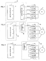
- FIG. 1 is a block diagram showing a first arrangement of a motor driving apparatus.
- a motor control unit 1 such as a numerical control unit generates a torque command (current command) as a motor driving command S on the basis of a motion command fed according to a program or the like, and feeds it to an intermediary unit 3.
- the intermediary unit 3 sends out motor driving commands (torque commands) for a plurality (four in the example shown in FIG. 1 ) of inverter units IV1 to IV4 arranged in parallel, so that the inverter units IV1 to IV4 drive-control a large-capacity motor 2.
- the motor control unit 1 sends out a motor driving command S in the form of parallel data
- the intermediary unit 3 feeds the motor driving command S to the inverter units IV1 to IV4 in the form of parallel data.
- FIG. 6 is a block diagram showing relevant components of the intermediary unit 3 for this parallel connection.
- the intermediary unit 3 comprises a receiver circuit 31, a setting circuit 32, an operation circuit 33, and drive circuits D1 to Dn corresponding in number to the inverter units IV1 to IVn.
- the motor driving command (torque command) S sent out from the motor control unit 1 in the form of parallel data is received by the receiver circuit 31.
- the coefficients A1 to An are set in advance by the setting circuit 32. If all the coefficients A1 to An are set to be "1", it means that the motor 2 is driven with a motor driving command (torque command) having n times the value of the motor driving command S sent from the motor control unit. Thus, the motor 2 is driven by a large current. In the example of FIG. 1 , the motor 2 is driven with 4 times the value of the motor driving command S.
- the coefficients A1 to An may be set to be the same value, for example "1".
- the coefficients A1 to An for the inverter units IV1 to IVn should be set corresponding to the differences among the inverter units IV1 to IVn, and then adjusted so that the total output of the inverter units IV1 to IVn will be an optimum value within the capacity range of the large-capacity motor 2.
- a motor driving apparatus suitable for the capacity of the motor 2 can be obtained.
- FIG. 2 is a block diagram showing a second arrangement of a motor driving apparatus.
- a plurality (four in FIG. 2 ) of inverter units IV1 to IV4 are serial-connected to a motor control unit 1, and a large-capacity motor 4 is a motor having four pairs of phase windings.
- the motor control unit 1 sends out a motor driving command (torque command) S in the form of serial data.
- An intermediary unit 5 receives the motor driving command S in the form of serial data, obtains motor driving commands for the inverter units IV1 to IV4, and send them out in the form of serial data at predetermined intervals.
- the inverter units IV1 to IV4 are connected in the daisy chain mode.
- the inverter units IV1 to IV4 each operate receiving their own motor driving command and control the drive voltage for their corresponding pair of windings.
- the. motor 4 has four pairs of windings, and four inverter units are provided so that each will supply and control the drive voltage for one of the four pairs of phase windings.
- FIG. 7 is a block diagram showing relevant components of the intermediary unit 5 used for this serial connection.
- the intermediary unit 5 comprises a receiver circuit 51, a setting circuit 52, a serial-parallel converting circuit 53, an operation circuit 54, a parallel-serial converting circuit 55 and a driver circuit 56.
- the motor control unit 1 sends out a motor driving command (torque command) S in the form of serial data, which is received by the receiver circuit 51.
- the serial-parallel converting circuit 53 converts the serial data into parallel data.
- motor driving commands (torque commands) S ⁇ A1 to S ⁇ An for the inverter units IV1 to IVn.
- the motor driving commands S ⁇ A1 to S ⁇ An for the inverter units IV1 to IVn obtained are converted into serial data by the parallel-serial converting circuit 55, and sent out through the driver circuit 56 at predetermined intervals.
- the inverter units IV1 to IVn each read their own motor driving command (torque command), perform inverter-control on the basis of the command read, and thereby supply the drive voltage to their corresponding pair of windings of the motor 4 to drive-control the motor 4.
- the coefficients A1 to An for the inverter units IV1 to IVn are freely set in the setting circuit 52.
- the intermediary unit 5 is similar to the intermediary unit 3 used for parallel connection shown in FIG. 6 .
- FIG. 3 is a block diagram showing a third arrangement of a motor driving apparatus.
- the third arrangement of a motor driving apparatus is an example in which a large-capacity motor 2 having a single pair of windings is drive-controlled by the inverter units IV1 to IV4 serial-connected to the motor control unit 1 shown in FIG. 2 .
- the intermediary unit 5 used for serial connection From a motor driving command S in the form of serial data sent out from the motor control device 1, the intermediary unit 5 used for serial connection generates motor driving commands S ⁇ A1 to S ⁇ A4 for the inverter units IV1 to IV4, and sends them out.
- the process up to here is the same as that in the second arrangement of a motor driving apparatus shown in FIG. 2 .
- the only difference is that the inverter units IV1 to IV4 drive-control the single pair of windings simultaneously (in this respect, the third arrangement of a motor driving apparatus is similar to the first arrangement of a motor driving apparatus shown in FIG. 1 ).
- the first arrangement of a motor driving apparatus shown in FIG. 1 can be arranged to drive a motor having a plurality of pairs of windings, for example the motor 4 having four pairs of phase windings shown in FIG. 2 .
- the output lines from the inverter units IV1 to IV4 in FIG. 1 are connected to their corresponding pairs of windings.
- the pairs of phase windings and the inverter units do not always need to be connected one-to-one as shown in FIG. 2 . It may be so arranged that a pair of windings is driven by a plurality of inverter units.
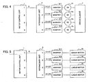
- FIG. 4 is a block diagram showing a fourth arrangement of a motor driving apparatus.
- a plurality (four) of motors 6 1 to 6 4 are provided to drive a single driven element 7.
- the motor control unit 1 sends out a single motor driving command (torque command) S in the form of parallel data, and the intermediary unit 3 for parallel connection shown in FIG. 6 generates motor driving commands (torque commands) S ⁇ A1 to S ⁇ A4 for the inverter units IV1 to IV4 to drive the inverter units IV1 to IV4, individually.
- the process up to here is the same as that in the first arrangement of a motor driving apparatus and therefore will not be described in detail.
- the difference between the fourth and first arrangements is that the inverter units IV1 to IV4 each drive their corresponding one of the motors 6 1 to 6 4 so that the driven element 7 will be driven by the total output of these motors.
- motor driving commands S ⁇ A1 to S ⁇ A4 each proportional to the motor driving command S are fed to the inverter units IV1 to IV4 simultaneously, and the inverter units IV1 to IV4 drive their corresponding motors 6 1 to 6 4 .
- the motors are driven in synchronization, and the driven element 7 is driven by the total torque of the plurality (four) of motors 6 1 to 6 4 .
- the fourth arrangement of a motor driving apparatus is an example in which the inverter units IV1 to IV4 are parallel-connected to the motor control device 1, the inverter units may be serial-connected to the motor control device as shown in FIG. 2 to drive a plurality of motors to drive a single driven element 7.
- the inverter units IV1 to IV4 are each connected to one of the four motors so that a driven element 7 will be driven by all the four motors.
- FIG. 5 is a block diagram showing a fifth arrangement of a motor driving apparatus.
- the apparatus is applied to linear motors.
- the only difference between the fifth arrangement of a motor driving apparatus and the fourth arrangement of a motor driving apparatus shown in FIG. 4 is that linear motors 8 1 to 8 4 are used in place of the motors 6.
- the motor control unit 1 sends out a single motor driving command (torque command) S in the form of parallel data.
- the intermediary unit 3 for parallel connection shown in FIG. 6 generates motor driving commands (torque commands) S ⁇ A1 to S ⁇ A4 for the inverter units IV1 to IV4 to drive the inverter units IV1 to IV4, individually.
- the process up to here is the same as that in the first and fourth arrangement of a motor driving apparatus and therefore will not be described in detail.
- the inverter units each drive their corresponding one of the linear motors 8 1 to 8 4 .
- the sliders of the linear motors 8 1 to 8 4 are connected to a driven element, and the driven element is driven by the total output torque of the plurality (four) of linear motors 8 1 to 8 4 .
- the inverter units IV1 to IV4 are parallel-connected, and the intermediary unit 3 for parallel connection shown in FIG. 6 is used.
- the inverter units may be serial-connected.
- the inverter units IV1 to IV4 may be serial-connected to the motor control device 1 as shown in FIG. 2 , using the intermediary unit 5 for serial connection shown in FIG. 7 .
- the intermediary unit 3 for parallel connection and the intermediary unit 5 for serial connection were described.
- the intermediary unit may be arranged to receive a motor driving command S in the form of serial data from the motor control unit 1 and feed motor driving commands S ⁇ A1 to S ⁇ A4 in the form of parallel data to the inverter units IV1 to IV4.
- an intermediary unit for feeding the motor driving commands S ⁇ A1 to S ⁇ A4 for the inverter units obtained in the operation circuit 54, in parallel is obtained by removing the parallel-serial converting circuit 55 and the driver circuit 56 from the arrangement shown in FIG. 7 and providing the driver circuits D1 to Dn shown in FIG. 6 , instead.
- this intermediary unit it may be so arranged that a motor driving command S from the motor control unit 1 in the form of serial data is fed to the inverter units IV1 to IV4 in parallel.
- the intermediary unit may be arranged to receive a motor driving command S in the form of parallel data, convert it into serial data and feed the inverter units IV1 to IV4 with motor driving commands S ⁇ A1 to SxA4 in the form of serial data. It may be so arranged that this intermediary unit converts a motor driving command S sent from the motor control unit 1 in the form of parallel data into motor driving commands for the inverter units IV1 to IV4 in the form of serial data, and feeds these drive commands to the inverter units IV1 to IV4 connected in the form of daisy chain as shown in FIG. 2 .
- the motor control unit 1 sends out a torque command (current command) as a motor driving command S.
- the motor control unit 1 makes a PWM command and sends out the PWM command as a motor driving command S.
- a PWM signal generating circuit does not need to be provided in each of the inverter units.
- the intermediary unit can be provided in a casing 91 of the motor control unit 1 as shown in FIG. 1 , or provided in a casing 92 independently of the casing 91 of the motor control unit 1 and a casing 93 of the inverter units. Alternatively, it can be provided in the casing 93 of the inverter units.
- the driving commands may be transmitted from the intermediary unit 3 or 5 to the inverter units IV1-IV4 as electric signals or as optical signals.
Landscapes
- Engineering & Computer Science (AREA)
- Human Computer Interaction (AREA)
- Manufacturing & Machinery (AREA)
- Physics & Mathematics (AREA)
- General Physics & Mathematics (AREA)
- Automation & Control Theory (AREA)
- Control Of Multiple Motors (AREA)
- Control Of Linear Motors (AREA)
Claims (10)
- Motorantriebsvorrichtung, umfassend
eine Motorsteuereinheit (1) zum Erzeugen eines Motorantriebsbefehls (S) gemäß einem eingegebenen Bewegungsbefehl;
eine Anzahl Invertereinheiten (IV1, IV2, IV3, IV4) zum jeweiligen Bereitstellen von Antriebsspannungen an eine Anzahl Sätze Wicklungsstränge eines einzelnen Motors (M), oder zum Bereitstellen von Antriebsspannungen an einen einzelnen Satz Wicklungsstränge eines einzelnen Motors (M); und
eine Zwischeneinheit (3), angeordnet zwischen der Motorsteuereinheit (1) und der Anzahl Invertereinheiten (IV1, IV2, IV3, IV4) zum Ausgeben von Antriebsbefehlen (S x A1, S x A2, S x A3, S x A4) an die Anzahl Invertereinheiten, auf der Basis eines von der Motorsteuereinheit (1) erzeugten Motorantriebsbefehls (S); wobei
die Zwischeneinheit (3), mit der Anzahl Invertereinheiten (IV1, IV2, IV3, IV4) verbunden ist zum Ausführen serieller Datenübertragung, und Antriebsbefehle (S x A1, S x A2, S x A3, S x A4) seriell an die Anzahl Invertereinheiten ausgibt, auf der Basis des gleichen von der Motorsteuereinheit (1) erzeugten Motorantriebsbefehls (S), wobei die Zwischeneinheit (3) eine Operationsschaltung (54) enthält zum Multiplizieren des Motorantriebsbefehls (S) mit einem jeweiligen voreingestellten Koeffizienten (A1...An) für jede entsprechende Invertereinheit (IV1, IV2, IV3, IV4) einzeln, um so die Antriebsbefehle (S xA1, S x A2, S x A3, S x A4) für die Anzahl Invertereinheiten zu erhalten. - Motorantriebsvorrichtung gemäß Anspruch 1, wobei die Antriebsbefehle (S x A1, S x A2, S x A3, S x A4) von der Zwischeneinheit (3) als elektrische Signale zur Anzahl Invertereinheiten (IV1, IV2, IV3, IV4) übertragen werden.
- Motorantriebsvorrichtung gemäß Anspruch 2, wobei die Motorsteuereinheit (1) einen Drehkraftbefehl als Motorantriebsbefehl (S) erzeugt.
- Motorantriebsvorrichtung gemäß Anspruch 2, wobei die Motorsteuereinheit (1) einen PWM-Befehl als Motorantriebsbefehl (S) erzeugt.
- Motorantriebsvorrichtung gemäß Anspruch 1, wobei die Antriebsbefehle (S x A1, S x A2, S x A3, S x A4) von der Zwischeneinheit (3) als optische Signale zur Anzahl Invertereinheiten (IV1, IV2, IV3, IV4) übertragen werden.
- Motorantriebsvorrichtung gemäß Anspruch 5, wobei die Motorsteuereinheit (1) einen Drehkraftbefehl als Motorantriebsbefehl (S) erzeugt.
- Motorantriebsvorrichtung gemäß Anspruch 5, wobei die Motorsteuereinheit (1) einen PWM-Befehl als Motorantriebsbefehl (S) erzeugt.
- Motorantriebsvorrichtung gemäß Anspruch 1, wobei ein Gehäuse (92) der Zwischeneinheit (3) unabhängig von einem Gehäuse (91) der Motorsteuereinheit (1) und dem Gehäuse (93) der Anzahl Invertereinheiten (IV1, IV2, IV3, IV4) bereitgestellt wird.
- Motorantriebsvorrichtung gemäß Anspruch 1, wobei die Zwischeneinheit (3) in einem Gehäuse (91) der Motorsteuereinheit (1) bereitgestellt wird.
- Motorantriebsvorrichtung gemäß Anspruch 1, wobei die Zwischeneinheit (3) in einem Gehäuse (93) der Anzahl Invertereinheiten (IV1, IV2, IV3, IV4) bereitgestellt wird.
Applications Claiming Priority (2)
| Application Number | Priority Date | Filing Date | Title |
|---|---|---|---|
| JP2003316832 | 2003-09-09 | ||
| JP2003316832A JP2005086918A (ja) | 2003-09-09 | 2003-09-09 | モータ駆動装置 |
Publications (3)
| Publication Number | Publication Date |
|---|---|
| EP1515425A2 EP1515425A2 (de) | 2005-03-16 |
| EP1515425A3 EP1515425A3 (de) | 2006-12-27 |
| EP1515425B1 true EP1515425B1 (de) | 2012-06-20 |
Family
ID=34131961
Family Applications (1)
| Application Number | Title | Priority Date | Filing Date |
|---|---|---|---|
| EP04255455A Expired - Lifetime EP1515425B1 (de) | 2003-09-09 | 2004-09-09 | Stromversorgungsvorrichtung für einen Motor |
Country Status (4)
| Country | Link |
|---|---|
| US (1) | US7196488B2 (de) |
| EP (1) | EP1515425B1 (de) |
| JP (1) | JP2005086918A (de) |
| CN (1) | CN1277349C (de) |
Families Citing this family (27)
| Publication number | Priority date | Publication date | Assignee | Title |
|---|---|---|---|---|
| US8508508B2 (en) | 2003-02-14 | 2013-08-13 | Next Holdings Limited | Touch screen signal processing with single-point calibration |
| US7629967B2 (en) | 2003-02-14 | 2009-12-08 | Next Holdings Limited | Touch screen signal processing |
| US8456447B2 (en) | 2003-02-14 | 2013-06-04 | Next Holdings Limited | Touch screen signal processing |
| US7538759B2 (en) | 2004-05-07 | 2009-05-26 | Next Holdings Limited | Touch panel display system with illumination and detection provided from a single edge |
| US7596008B2 (en) * | 2005-02-25 | 2009-09-29 | Mitsubishi Electric Corporation | Power conversion apparatus |
| FI119136B (fi) * | 2006-06-06 | 2008-07-31 | Abb Oy | Sähkökäyttöjärjestelmä |
| KR101440644B1 (ko) * | 2006-08-02 | 2014-09-22 | 티에치케이 가부시끼가이샤 | 동력 분기 시스템 및 동력 분기 방법 |
| FI118875B (fi) * | 2006-09-26 | 2008-04-15 | Vacon Oyj | Invertterien rinnankytkentä |
| WO2008038695A1 (en) * | 2006-09-29 | 2008-04-03 | Thk Co., Ltd. | Method for controlling ac linear motors, device for driving ac linear motors, and system of ac linear motors |
| JP4137967B2 (ja) * | 2006-11-20 | 2008-08-20 | ファナック株式会社 | モータ制御装置 |
| JP4987495B2 (ja) | 2007-01-25 | 2012-07-25 | 株式会社東芝 | 鉄道車両駆動用モータドライブシステム |
| EP2135155B1 (de) | 2007-04-11 | 2013-09-18 | Next Holdings, Inc. | Touchscreen-system mit gleit- und klick-eingabeverfahren |
| US20080258661A1 (en) * | 2007-04-23 | 2008-10-23 | Nagashima James M | Inverter topology for an electric motor |
| CA2689682A1 (en) * | 2007-06-07 | 2008-12-11 | Mitsubishi Electric Corporation | Motor controlling apparatus |
| CA2697856A1 (en) | 2007-08-30 | 2009-03-05 | Next Holdings, Inc. | Low profile touch panel systems |
| CN101802760B (zh) | 2007-08-30 | 2013-03-20 | 奈克斯特控股有限公司 | 具有改进照明的光学触摸屏 |
| RU2360354C1 (ru) * | 2007-12-04 | 2009-06-27 | Олег Анатольевич Буглаев | Вентильный электродвигатель |
| US8405636B2 (en) | 2008-01-07 | 2013-03-26 | Next Holdings Limited | Optical position sensing system and optical position sensor assembly |
| JP4390835B2 (ja) | 2008-02-04 | 2009-12-24 | ファナック株式会社 | サーボモータ制御システム |
| JP4580023B2 (ja) | 2009-03-02 | 2010-11-10 | ファナック株式会社 | 複数の巻線を備えたモータを駆動するモータ駆動システム |
| CN102273058B (zh) * | 2009-11-26 | 2014-07-23 | 松下电器产业株式会社 | 负载驱动系统、电动机驱动系统以及车辆控制系统 |
| JP6552314B2 (ja) * | 2015-07-24 | 2019-07-31 | 日本電産サンキョー株式会社 | モータ制御装置 |
| US10348222B2 (en) * | 2016-08-26 | 2019-07-09 | Deere & Company | Systems and methods for reducing DC link voltage dynamics with limited energy storage element |
| US10632999B2 (en) | 2018-08-21 | 2020-04-28 | Deere & Company | Observer based load power estimation method for hybrid electric vehicles |
| US11682997B2 (en) * | 2021-05-17 | 2023-06-20 | Hitachi Astemo Americas, Inc. | Rotary electric machine with selectable coil control |
| DE102021121936A1 (de) | 2021-08-24 | 2023-03-02 | Dr. Ing. H.C. F. Porsche Aktiengesellschaft | Elektrisch oder teilelektrisch angetriebenes Fahrzeug mit einem stromgeregelten Pulswechselrichter |
| JP2023117870A (ja) | 2022-02-14 | 2023-08-24 | オムロン株式会社 | ドライブシステム |
Citations (1)
| Publication number | Priority date | Publication date | Assignee | Title |
|---|---|---|---|---|
| EP0588628A1 (de) * | 1992-09-17 | 1994-03-23 | Hitachi, Ltd. | Steuersystem für Elektrofahrzeug |
Family Cites Families (26)
| Publication number | Priority date | Publication date | Assignee | Title |
|---|---|---|---|---|
| JPS61154493A (ja) | 1984-12-26 | 1986-07-14 | Fanuc Ltd | サーボモータの駆動制御装置 |
| US4825144A (en) * | 1987-11-10 | 1989-04-25 | Motorola, Inc. | Dual channel current mode switching regulator |
| US5031088A (en) * | 1989-03-31 | 1991-07-09 | Kabushiki Kaisha Toshiba | Variable-voltage and variable-frequency power converter |
| JPH072037B2 (ja) | 1989-07-03 | 1995-01-11 | 日本オーチス・エレベータ株式会社 | エレベータ駆動用のインバータ制御装置 |
| JP2883643B2 (ja) * | 1989-09-04 | 1999-04-19 | 富士電機 株式会社 | インバータの群運転方法 |
| CA2074176A1 (en) * | 1990-11-19 | 1992-05-20 | Ronald Rohner | Method and device for switching inverters in parallel |
| JPH06141550A (ja) * | 1992-10-19 | 1994-05-20 | S G:Kk | インバータ装置及びモータ制御システム |
| JPH06197593A (ja) | 1992-12-25 | 1994-07-15 | Toyota Motor Corp | Pwm制御モータ装置 |
| JPH07213095A (ja) | 1994-01-20 | 1995-08-11 | Fuji Electric Co Ltd | 永久磁石型同期電動機の駆動装置 |
| JPH07222456A (ja) | 1994-01-31 | 1995-08-18 | Meidensha Corp | インバータ・システム |
| US5657217A (en) * | 1994-03-02 | 1997-08-12 | Kabushiki Kaisha Yaskawa Denki | Multi-coupled power conversion system and control method for the same |
| JP3595357B2 (ja) | 1994-06-30 | 2004-12-02 | ファナック株式会社 | ディジタルサーボによるタンデム制御方法 |
| JPH0835713A (ja) * | 1994-07-26 | 1996-02-06 | Fujitsu General Ltd | 空気調和機の制御方法およびその装置 |
| JPH09205797A (ja) | 1996-01-25 | 1997-08-05 | Takao Kawabata | 交流電動機の可変速駆動装置 |
| JPH09331694A (ja) | 1996-06-10 | 1997-12-22 | Toshiba Corp | インバータモータ |
| DE69726086T2 (de) * | 1996-09-25 | 2004-08-19 | Hitachi, Ltd. | Steuervorrichtung für ein elektrisches Fahrzeug |
| JPH10136690A (ja) | 1996-10-29 | 1998-05-22 | Matsushita Electric Ind Co Ltd | 電動機制御装置 |
| JPH11356090A (ja) | 1998-06-10 | 1999-12-24 | Japan Steel Works Ltd:The | 電動射出成形機のモータ制御装置 |
| JP4187308B2 (ja) * | 1998-06-16 | 2008-11-26 | 日本オーチス・エレベータ株式会社 | 可変速駆動装置 |
| US6377478B1 (en) * | 1999-05-28 | 2002-04-23 | Toshiba International Corporation | Inverter device |
| JP2001002207A (ja) | 1999-06-18 | 2001-01-09 | Toyota Autom Loom Works Ltd | 荷移載装置 |
| JP4229542B2 (ja) | 1999-09-13 | 2009-02-25 | 東芝エレベータ株式会社 | 交流電動機制御装置 |
| JP3316801B2 (ja) | 1999-09-16 | 2002-08-19 | 株式会社日立製作所 | 多重電力変換装置の制御方法及び多重電力変換装置 |
| JP3555567B2 (ja) * | 2000-09-04 | 2004-08-18 | 日産自動車株式会社 | 回転電機の制御装置 |
| US6653810B2 (en) * | 2001-01-12 | 2003-11-25 | Hewlett-Packard Development Company, L.P. | Motor control system |
| JP4641124B2 (ja) * | 2001-08-02 | 2011-03-02 | 本田技研工業株式会社 | 多重結合インバータ装置 |
-
2003
- 2003-09-09 JP JP2003316832A patent/JP2005086918A/ja active Pending
-
2004
- 2004-09-09 US US10/936,543 patent/US7196488B2/en not_active Expired - Lifetime
- 2004-09-09 CN CNB2004100737654A patent/CN1277349C/zh not_active Expired - Fee Related
- 2004-09-09 EP EP04255455A patent/EP1515425B1/de not_active Expired - Lifetime
Patent Citations (1)
| Publication number | Priority date | Publication date | Assignee | Title |
|---|---|---|---|---|
| EP0588628A1 (de) * | 1992-09-17 | 1994-03-23 | Hitachi, Ltd. | Steuersystem für Elektrofahrzeug |
Also Published As
| Publication number | Publication date |
|---|---|
| US7196488B2 (en) | 2007-03-27 |
| CN1595789A (zh) | 2005-03-16 |
| US20050052144A1 (en) | 2005-03-10 |
| JP2005086918A (ja) | 2005-03-31 |
| EP1515425A2 (de) | 2005-03-16 |
| EP1515425A3 (de) | 2006-12-27 |
| CN1277349C (zh) | 2006-09-27 |
Similar Documents
| Publication | Publication Date | Title |
|---|---|---|
| US7196488B2 (en) | Motor driving apparatus | |
| EP1484832B1 (de) | Gerät zur Motorsteuerung | |
| US6806660B2 (en) | Motor controlling serial communication device and motor driver | |
| CN101387887B (zh) | 一种混合动力电机和控制器测试平台的测试方法 | |
| US9401669B2 (en) | Motor controller for synchronously controlling multiple motors | |
| JP4182132B2 (ja) | モータ制御システム | |
| CZ299230B6 (cs) | Zpusob rízeného paralelního provozu jednosmernýchmenicu a zarízení k provádení tohoto zpusobu | |
| EP1521356A3 (de) | Regelung von parallel betriebenen Frequenzwandlern oder Umrichtern | |
| WO2004095670A3 (en) | Method and system for current sharing among a plurality of power modules | |
| JPH09224390A (ja) | モータ・コントロール・ネットワーク | |
| CN101917148A (zh) | 基于高压大功率变频器的主从控制方法 | |
| JPWO2002031959A1 (ja) | モータ駆動装置、モータ駆動制御方法、およびこれを用いた部品装着装置 | |
| US6914790B2 (en) | Motor driving controller | |
| US11757291B2 (en) | Power supply device | |
| EP0788041B1 (de) | Numerisches steuergerat | |
| US7183735B2 (en) | Drive unit for controlling drives in machine tools or production machines | |
| EP1579959B1 (de) | Intelligente Spindel zum Festziehen mit integriertem Messwertaufnehmer, Servoverstärker und Datenverarbeitungsanlage | |
| CN105573314A (zh) | 一种agv小车的控制方法 | |
| JP3645668B2 (ja) | モータ制御装置 | |
| EP3518050B1 (de) | Verfahren und steuerungssystem zur steuerung von parallel betriebenen vorrichtungen | |
| JP2008090825A (ja) | 位置検出器をマルチドロップ接続した多軸制御システム | |
| JP5301180B2 (ja) | 同期型acサーボモータおよびその制御システム | |
| US20230261464A1 (en) | Method of power transmission | |
| EP1487670B1 (de) | Teilen einer synchronen kommunikationsschnittstelle zum kommunizieren mit mehreren vorrichtungen | |
| EP1837131A1 (de) | Manipulator, zum Beispiel für einen Industrieroboter, und Antriebsvorrichtung für einen Manipulator |
Legal Events
| Date | Code | Title | Description |
|---|---|---|---|
| PUAI | Public reference made under article 153(3) epc to a published international application that has entered the european phase |
Free format text: ORIGINAL CODE: 0009012 |
|
| AK | Designated contracting states |
Kind code of ref document: A2 Designated state(s): AT BE BG CH CY CZ DE DK EE ES FI FR GB GR HU IE IT LI LU MC NL PL PT RO SE SI SK TR |
|
| AX | Request for extension of the european patent |
Extension state: AL HR LT LV MK |
|
| PUAL | Search report despatched |
Free format text: ORIGINAL CODE: 0009013 |
|
| AK | Designated contracting states |
Kind code of ref document: A3 Designated state(s): AT BE BG CH CY CZ DE DK EE ES FI FR GB GR HU IE IT LI LU MC NL PL PT RO SE SI SK TR |
|
| AX | Request for extension of the european patent |
Extension state: AL HR LT LV MK |
|
| 17P | Request for examination filed |
Effective date: 20070625 |
|
| AKX | Designation fees paid |
Designated state(s): DE |
|
| RAP1 | Party data changed (applicant data changed or rights of an application transferred) |
Owner name: FANUC CORPORATION |
|
| 17Q | First examination report despatched |
Effective date: 20110624 |
|
| REG | Reference to a national code |
Ref country code: DE Ref legal event code: R079 Ref document number: 602004038274 Country of ref document: DE Free format text: PREVIOUS MAIN CLASS: H02P0007630000 Ipc: H02P0027060000 |
|
| GRAP | Despatch of communication of intention to grant a patent |
Free format text: ORIGINAL CODE: EPIDOSNIGR1 |
|
| RIC1 | Information provided on ipc code assigned before grant |
Ipc: G05B 19/44 20060101ALI20111215BHEP Ipc: H02P 27/06 20060101AFI20111215BHEP |
|
| RIN1 | Information on inventor provided before grant (corrected) |
Inventor name: HORIKOSHI, SHINICHI,ROOM 14-206 Inventor name: SATO, HIROYASU,ROOM 12-307 Inventor name: MATSUBARA, SHUNSUKE |
|
| GRAS | Grant fee paid |
Free format text: ORIGINAL CODE: EPIDOSNIGR3 |
|
| GRAA | (expected) grant |
Free format text: ORIGINAL CODE: 0009210 |
|
| AK | Designated contracting states |
Kind code of ref document: B1 Designated state(s): DE |
|
| REG | Reference to a national code |
Ref country code: DE Ref legal event code: R096 Ref document number: 602004038274 Country of ref document: DE Effective date: 20120816 |
|
| PLBE | No opposition filed within time limit |
Free format text: ORIGINAL CODE: 0009261 |
|
| STAA | Information on the status of an ep patent application or granted ep patent |
Free format text: STATUS: NO OPPOSITION FILED WITHIN TIME LIMIT |
|
| 26N | No opposition filed |
Effective date: 20130321 |
|
| REG | Reference to a national code |
Ref country code: DE Ref legal event code: R097 Ref document number: 602004038274 Country of ref document: DE Effective date: 20130321 |
|
| PGFP | Annual fee paid to national office [announced via postgrant information from national office to epo] |
Ref country code: DE Payment date: 20180828 Year of fee payment: 15 |
|
| REG | Reference to a national code |
Ref country code: DE Ref legal event code: R119 Ref document number: 602004038274 Country of ref document: DE |
|
| PG25 | Lapsed in a contracting state [announced via postgrant information from national office to epo] |
Ref country code: DE Free format text: LAPSE BECAUSE OF NON-PAYMENT OF DUE FEES Effective date: 20200401 |