EP1515423A2 - Motorregelungssystem und mit diesem Motorregelungssystem ausgestattete Vakuumpumpe - Google Patents
Motorregelungssystem und mit diesem Motorregelungssystem ausgestattete Vakuumpumpe Download PDFInfo
- Publication number
- EP1515423A2 EP1515423A2 EP04255434A EP04255434A EP1515423A2 EP 1515423 A2 EP1515423 A2 EP 1515423A2 EP 04255434 A EP04255434 A EP 04255434A EP 04255434 A EP04255434 A EP 04255434A EP 1515423 A2 EP1515423 A2 EP 1515423A2
- Authority
- EP
- European Patent Office
- Prior art keywords
- motor
- current
- temperature
- control system
- driving circuit
- Prior art date
- Legal status (The legal status is an assumption and is not a legal conclusion. Google has not performed a legal analysis and makes no representation as to the accuracy of the status listed.)
- Withdrawn
Links
Images





Classifications
-
- H—ELECTRICITY
- H02—GENERATION; CONVERSION OR DISTRIBUTION OF ELECTRIC POWER
- H02P—CONTROL OR REGULATION OF ELECTRIC MOTORS, ELECTRIC GENERATORS OR DYNAMO-ELECTRIC CONVERTERS; CONTROLLING TRANSFORMERS, REACTORS OR CHOKE COILS
- H02P1/00—Arrangements for starting electric motors or dynamo-electric converters
- H02P1/16—Arrangements for starting electric motors or dynamo-electric converters for starting dynamo-electric motors or dynamo-electric converters
- H02P1/26—Arrangements for starting electric motors or dynamo-electric converters for starting dynamo-electric motors or dynamo-electric converters for starting an individual polyphase induction motor
- H02P1/28—Arrangements for starting electric motors or dynamo-electric converters for starting dynamo-electric motors or dynamo-electric converters for starting an individual polyphase induction motor by progressive increase of voltage applied to primary circuit of motor
-
- F—MECHANICAL ENGINEERING; LIGHTING; HEATING; WEAPONS; BLASTING
- F04—POSITIVE - DISPLACEMENT MACHINES FOR LIQUIDS; PUMPS FOR LIQUIDS OR ELASTIC FLUIDS
- F04D—NON-POSITIVE-DISPLACEMENT PUMPS
- F04D19/00—Axial-flow pumps
- F04D19/02—Multi-stage pumps
- F04D19/04—Multi-stage pumps specially adapted to the production of a high vacuum, e.g. molecular pumps
-
- F—MECHANICAL ENGINEERING; LIGHTING; HEATING; WEAPONS; BLASTING
- F04—POSITIVE - DISPLACEMENT MACHINES FOR LIQUIDS; PUMPS FOR LIQUIDS OR ELASTIC FLUIDS
- F04D—NON-POSITIVE-DISPLACEMENT PUMPS
- F04D27/00—Control, e.g. regulation, of pumps, pumping installations or pumping systems specially adapted for elastic fluids
- F04D27/02—Surge control
- F04D27/0261—Surge control by varying driving speed
-
- F—MECHANICAL ENGINEERING; LIGHTING; HEATING; WEAPONS; BLASTING
- F05—INDEXING SCHEMES RELATING TO ENGINES OR PUMPS IN VARIOUS SUBCLASSES OF CLASSES F01-F04
- F05D—INDEXING SCHEME FOR ASPECTS RELATING TO NON-POSITIVE-DISPLACEMENT MACHINES OR ENGINES, GAS-TURBINES OR JET-PROPULSION PLANTS
- F05D2260/00—Function
- F05D2260/85—Starting
-
- Y—GENERAL TAGGING OF NEW TECHNOLOGICAL DEVELOPMENTS; GENERAL TAGGING OF CROSS-SECTIONAL TECHNOLOGIES SPANNING OVER SEVERAL SECTIONS OF THE IPC; TECHNICAL SUBJECTS COVERED BY FORMER USPC CROSS-REFERENCE ART COLLECTIONS [XRACs] AND DIGESTS
- Y02—TECHNOLOGIES OR APPLICATIONS FOR MITIGATION OR ADAPTATION AGAINST CLIMATE CHANGE
- Y02B—CLIMATE CHANGE MITIGATION TECHNOLOGIES RELATED TO BUILDINGS, e.g. HOUSING, HOUSE APPLIANCES OR RELATED END-USER APPLICATIONS
- Y02B30/00—Energy efficient heating, ventilation or air conditioning [HVAC]
- Y02B30/70—Efficient control or regulation technologies, e.g. for control of refrigerant flow, motor or heating
Definitions
- a turbo molecular pump is used in a movable simple vacuum chamber, or in order to place a flat panel display manufacturing apparatus in a vacuum state.
- the turbo molecular pump main body 100 has an inlet port 101 formed at the upper end of a round outer cylinder 127.
- a rotary member 103 in the periphery of which there are formed radially and in a number of stages a plurality of rotary vanes 102a, 102b, 102c, ... consisting of turbine blades for sucking and evacuating gases.
- the upper radial electromagnet 104 is excitation-controlled through a compensation circuit with a PID adjustment function (not shown in the drawings) based on the displacement signal obtained through detection by the upper radial sensor 107, thus adjusting the upper radial position of the rotor shaft 113.
- axial electromagnets 106A and 106B are arranged so as to sandwich from above and below a circular metal disc 111 provided in the lower portion of the rotor shaft 113.
- the metal disc 111 is formed of a high magnetic-permeability material, such as iron.
- a rotary vane 102d which extends vertically downwards.
- the outer peripheral surface of the rotary vane 102d is cylindrical, and protrudes toward the inner peripheral surface of the threaded spacer 131 so as to be in close proximity to the threaded spacer 131 with a predetermined gap therebetween.
- the threaded spacer 131 is arranged in the outer periphery of the rotary vane 102d, and the thread grooves 131a are formed in the inner peripheral surface of the threaded spacer 131.
- the thread grooves may be formed in the outer peripheral surfaces of the rotary vane 102d, and a spacer with a cylindrical inner peripheral surface may be arranged in the periphery thereof.
- piping (not shown in the drawings) is arranged in the base portion 129, and the purge gas is introduced through the piping.
- the purge gas thus introduced flows through the gaps between a protective bearing 120 and the rotor shaft 113, between the rotor and stator of the motor 121, and between the stator column 122 and the rotary vanes 102 before being transmitted to the exhaust port 133.
- the electronic circuit portion 141 is formed by a semiconductor memory, such as EEP-ROM, an electronic component for the access thereto, such as a semiconductor device, a substrate 143 for the mounting thereof, etc.
- the electronic circuit portion 141 is accommodated in the lower portion near the center of the base portion 129 constituting the lower portion of the turbo molecular pump main body 100, and is closed by a hermetic bottom cover 145.
- the process gas may be introduced into the chamber in a high temperature state. When it reaches a certain temperature by being cooled at the time of evacuation, such process gas may be solidified to precipitate a product in the exhaust system. Then, when such process gas is cooled and solidified in the turbo molecular pump main body 100, it adheres to the inner wall of the turbo molecular pump main body 100 and is deposited thereon.
- the deposit narrows the pump flow path, which leads to a deterioration in the performance of the turbo molecular pump main body 100.
- the above-mentioned product is likely to solidify and adhere to the portion near the exhaust port, in particular, near the rotary vanes 102 and the threaded spacer 131, where the temperature is low.
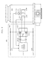
- a motor control system 300 is equipped with the motor 121 on the turbo molecular pump main body 100 side.
- the motor 121 is equipped with an RPM detecting sensor 124 on the stator side thereof.
- the RPM detecting sensor 124 is arranged so as to surround the rotor shaft 113, and consists, for example, of a semiconductor Hall sensor.
- the RPM detecting sensor 124 detects the rotating magnetic flux density of the motor 121, thereby detecting the RPM of the rotor shaft 113.
- motor windings 126U, 126V, and 126W are connected to a motor driving circuit 220 on the control device 200 side.
- a DC voltage is supplied to the motor driving circuit 220 from a power source 230 (In the drawing, the + side will be referred to as a positive pole 230a, and the - side will be referred to as a negative pole 230b).
- the motor driving circuit 220 is equipped with inverter circuits 222 (only one of which is shown in the drawing) respectively corresponding to the motor windings 126U, 126V, and 126W, and power is supplied to the motor windings 126U, 126V, and 126W through the inverter circuits 222.
- Each of these inverter circuits 222 is composed, for example, of two transistors 222a and 222b for one motor winding 126U.
- a drive signal is input to the motor driving circuit 220 from a drive control circuit 210.
- the power supplied from the inverter circuits 222 to the motor windings 126U, 126V, and 126W is controlled.
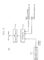
- Fig. 9 is a block diagram showing the drive control circuit.
- a command signal is input to the comparator 212 from a reference value setting circuit 214, and this command signal is a signal indicating, for example, a reference RPM.
- the comparator 212 compares, for example, the reference RPM indicated by the command signal with the detection signal from the RPM detecting sensor 124 to effect PID compensation, and, further, compares this output signal as a current command value with the detection signals from the motor current detecting sensors 128 to effect PID compensation. Thereafter, the comparator 212 outputs this output signal to a PWM control circuit 216.
- the comparator 212 is equipped with a current limiter circuit (not shown in the drawings) , and this current limiter circuit performs control based on the comparison result output to the PWM control circuit 216 such that the motor current Im supplied to each of the inverter circuits 222 and the motor windings 126U, 126V, and 126W does not exceed a fixed upper limit value.
- the PWM control circuit 216 performs pulse width control (PWM control) on the drive signal.
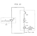
- Equation 1 L and R are the inductance component and the resistance component, respectively, of the motor windings 126U, 126V, and 126W, and K is the counter electromotive force constant of the motor windings 126U, 126V, and 126W; E is the drive voltage supplied from the inverter circuits 222.
- the motor current Im that can be supplied to the inverter circuits 222 and the motor windings 126U, 126V, and 126W is theoretically in conformity with Equation 1.
- the magnitude of the motor current Im when the rotating speed ⁇ of the rotor shaft 113 is a rated RPM is referred to as the rated rotation current value Ir.
- the PWM control circuit 216 outputs a PWM-controlled drive signal to the inverter circuits 222 in the motor driving circuit 220, whereby power is supplied to the motor windings 126U, 126V, and 126W from the motor driving circuit 220, and an AC voltage is generated in the motor windings 126U, 126V, and 126W. Further, a torque corresponding to the motor current Im at this time is generated in the rotor shaft 113.
- the inverter circuits 222 and the motor windings 126U, 126V, and 126W reliably and safely in the range of the RPM of the rotor 113 from zero to the rated RPM.
- the rated rotation current value Ir which is the motor current Im when the rotor shaft 113 is at rated RPM, to allow a leeway in terms of safety.
- Fig. 11A shows the relationship between the starting time of the turbo molecular pump and the RPM of the rotor shaft 113
- Fig. 11B shows the relationship between the RPM of the rotor shaft 113 at this time and the motor current Im.
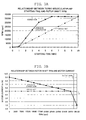
- the rated RPM of the rotor shaft 113 is approximately 37000 (rpm).
- a current value Ir at rated rotation is set as the upper limit of the motor current Im thereof, so that no torque in excess of the current value Ir at rated rotation is imparted to the rotor shaft 113, and the starting of the turbo molecular pump cannot be said to be quick enough.
- the shipment of the turbo molecular pump involves a process in which the starting and stopping of the turbo molecular pump is repeated in order to inspect and evaluate the same; since the starting of the turbo molecular pump is slow, there is a fear of the production period for the turbo molecular pump becoming rather long.
- a flat panel display will tend to increase in size
- the turbo molecular pump will also tend to increase in size in order to improve the vacuum performance of the manufacturing apparatus for such a large flat panel display.
- a turbo molecular pump equipped with the conventional motor control system 300 there is a fear of its starting becoming still slower.
- the present invention is made in view of the above problems in the prior art, and an object thereof is to provide a motor control system capable of shortening the starting time of a turbo molecular pump and a vacuum pump equipped with the motor control system.
- the present invention relates to a motor control system including: a rotary member; a motor for imparting a torque to the rotary member; a motor driving circuit for supplying power to the motor; and drive control means for controlling a motor current supplied to the motor, characterized in that the motor current is controlled by using as a set value a value of a motor current Im calculated by Equation 1.
- the motor current Im calculated by Equation 1 is a theoretical motor current value obtained from the motor and an equivalent circuit for the motor driving circuit.
- the motor current supplied to the motor is controlled by using this calculated value of the motor current Im as a set value.
- To control the motor current within the safety range for the motor and the motor driving circuit it is desirable to determine a leeway in Equation 1. This leeway is obtained in advance by, for example, experiment or calculation.
- the set value of the motor current is an upper limit value or a command value.
- the motor current is controlled within the range of the current value at continuous rating of the motor and the motor driving circuit.
- the motor current is controlled within the range of the current value at continuous rating of the motor and the motor driving circuit.
- the set value setting means in accordance with the characteristic curve and based on the temperature detected by the temperature detecting means, the current value at short-term rating of the motor and the motor driving circuit at this temperature is set as the set value.
- the motor current within a range not less than the current value at continuous rating.
- the motor control system of the present invention is mounted in a vacuum pump.
- the process before shipment which requires the vacuum pump to be started and stopped repeatedly, can be conducted quickly, thereby making it possible to shorten the production period for the vacuum pump.
- the starting time for restarting the vacuum pump can be shortened, which makes it possible to regain the requisite vacuum degree inside the chamber promptly.
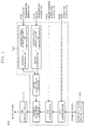
- Fig. 1 shows the configuration of a motor control system according to an embodiment of the present invention.
- the components that are the same as those of Fig. 8 are indicated by the same symbols, and a description thereof will be omitted.
- a motor control system 600 includes a turbo molecular pump main body 400, in which motor windings 126U, 126V, and 126W are equipped with a motor temperature sensor 424.
- the motor temperature sensor 424 consists, for example, of a thermistor, which is adapted to detect the temperature of the motor windings 126U, 126V, and 126W.
- Detection signals from the motor temperature sensor 424 and the inverter temperature sensor 524 are input to a drive control circuit 510 described below.
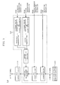
- Fig. 2 is a block diagram showing this drive control circuit.
- the components that are the same as those of Fig. 9 are indicated by the same symbols, and a description thereof will be omitted.
- the drive control circuit 510 includes a comparator 512, to which there are input the detection signals from the motor temperature sensor 424 and the inverter temperature sensor 524. Further, as in the case of the conventional comparator 212, input to the comparator 512 are a command signal from the reference value setting circuit 214 and detection signals from the RPM detecting sensor 124 and the motor current detecting sensor 128.
- this comparator 512 is equipped, instead of the current limiter circuit provided in the conventional comparator 212, with a current adjustment circuit.
- the upper limit value of the motor current Im is set so as to be variable in accordance with a characteristic curve described below.
- the comparator 512 is equipped with a characteristic curve defining the relationship between the temperatures of the motor windings 126U, 126V, and 126W and the inverter circuits 222 and the current value at continuous rating of the motor windings 126U, 126V, and 126W and the inverter circuits 222 at that temperature.
- This characteristic curve is obtained in advance by table making through experiment or by calculation through modeling of the drive control circuit 510, the motor 121, etc. Further, this characteristic curve may be set so as to be fixed inside the control device 500, etc. or so as to allow rewriting from the outside.
- the motor current Im at the start of the turbo molecular pump of the present invention is larger than the motor current Im in the prior art. The reason for this will be explained below.
- the current value Ir at rated rotation is constantly set as the upper limit value of the motor current Im set in the current limiter circuit.
- the current value Ir at rated rotation is not used as the upper limit value of the motor current Im. According to the relationship of Equation 1 as described above, at the start of the turbo molecular pump, it is theoretically possible to provide a motor current Im not less than the rated rotation current value Ir.
- the motor temperature sensor 424 and the inverter temperature sensor 524 which respectively detect the temperatures of the inverter circuits 222 and the motor windings 126U, 126V, and 126W. Then, in the comparator 512, the upper limit value of the motor current Im is set based on the temperatures of the inverter circuits 222 and the motor windings 126U, 126V, and 126W.
- the motor current Im is controlled in accordance with the characteristic curve and within the range of the current value at continuous rating satisfying both the motor windings 126U, 126V, and 126W and the inverter circuits 222.
- the motor current Im is controlled in accordance with the characteristic curve and within the range of the current value at continuous rating satisfying both the motor windings 126U, 126V, and 126W and the inverter circuits 222.
- Fig. 3A shows the relationship between the starting time of the turbo molecular pump and the RPM of the rotor shaft 113
- Fig. 3B shows the relationship between the RPM of the rotor shaft 113 at this time and the motor current Im.
- the components that are the same as those of Figs. 11A and 11B are indicated by the same symbols, and a description thereof will be omitted.
- the motor current Im at the start of the turbo molecular pump is larger than the motor current Im in the prior art. This is due to the fact that the current value Ir at rated rotation in the prior art is not used as the upper limit value of the motor current Im and that, theoretically, it is possible to supply a motor current Im according to the relationship of Equation 1.
- the motor current Im immediately after the start of the turbo molecular pump is approximately 9A, which is smaller than the value of the motor current Im calculated by Equation 1.
- the upper limit value of the motor current Im set in the current adjustment circuit in the comparator 512 is the current value at continuous rating, which satisfies both the motor windings 126U, 126V, and 126W and the inverter circuits 222.
- the process before shipment which requires the turbo molecular pump to be started and stopped repeatedly, can be conducted quickly, thereby making it possible to shorten the production period for the turbo molecular pump.
- the turbo molecular pump is increased in size to be in conformity with manufacturing apparatus for a large flat panel display, it is possible to shorten its starting time. Thus, it is possible to shorten the start-up time of the manufacturing apparatus for the large flat panel display. Further, when applied to a turbo molecular pump of conventional size, the present invention helps to shorten the start-up time of a semiconductor manufacturing apparatus, an electron microscope, etc.
- the motor current Im is controlled in the current adjustment circuit of the comparator 512 so as to be within the range of the current value at continuous rating as indicated by the characteristic curve, whereby making it possible to prevent breakdown of these components.
- the comparator 512 sets, as the upper limit value of the motor current Im, the current value at continuous rating satisfying both of the components at the temperature in accordance with the characteristic curve and based on the temperatures detected by the motor temperature sensor 424 and the inverter temperature sensor 524, this should not be construed restrictively.
- the motor current Im is controlled within the range of the current value at continuous rating satisfying both of the components, the motor windings 126U, 126V, and 126W and the inverter circuits 222, this should not be construed restrictively.
- a permissible time is first selected, and a characteristic curve corresponding to this permissible time is selected.
- the comparator 512 sets the upper limit value of the motor current Im based on the temperatures detected by the motor temperature sensor 424 and the inverter temperature sensor 524.
- Fig. 6 is a time chart showing an example of how the motor current Im is controlled in this case.
- the current value IL constitutes the current value at continuous rating.
- the current value IH constitutes the current value at short-term rating of the motor windings 126U, 126V, and 126W and the inverter circuits 222 at the temperatures at that time, in accordance with the characteristic curve corresponding to the permissible time tH determined by the comparator 512.
- the current value IH is controlled based on the characteristic curve at short-term rating with respect to the motor windings 126U, 126V, and 126W and the inverter circuits 222, so that it is possible to prevent breakdown of these components in a critical state.
- the temperature detecting means for detecting the temperatures of the motor and the motor driving circuit
- the set value setting means for, based on the temperature detected by the temperature detecting means, setting the current value at continuous rating at the temperature as the set value of the motor current, whereby it is possible to prevent excessive supply of motor current to the motor and the motor driving circuit.
- the current value at short-term rating of the motor and the motor driving circuit is set as the set value of the motor current, whereby it is possible to further shorten the motor starting time.
Landscapes
- Engineering & Computer Science (AREA)
- Mechanical Engineering (AREA)
- General Engineering & Computer Science (AREA)
- Power Engineering (AREA)
- Non-Positive Displacement Air Blowers (AREA)
- Control Of Motors That Do Not Use Commutators (AREA)
- Control Of Positive-Displacement Air Blowers (AREA)
Applications Claiming Priority (2)
| Application Number | Priority Date | Filing Date | Title |
|---|---|---|---|
| JP2003318761A JP2005083316A (ja) | 2003-09-10 | 2003-09-10 | モータ制御システム及び該モータ制御システムを搭載した真空ポンプ |
| JP2003318761 | 2003-09-10 |
Publications (2)
| Publication Number | Publication Date |
|---|---|
| EP1515423A2 true EP1515423A2 (de) | 2005-03-16 |
| EP1515423A3 EP1515423A3 (de) | 2006-02-01 |
Family
ID=34132009
Family Applications (1)
| Application Number | Title | Priority Date | Filing Date |
|---|---|---|---|
| EP04255434A Withdrawn EP1515423A3 (de) | 2003-09-10 | 2004-09-08 | Motorregelungssystem und mit diesem Motorregelungssystem ausgestattete Vakuumpumpe |
Country Status (3)
| Country | Link |
|---|---|
| US (1) | US7245097B2 (de) |
| EP (1) | EP1515423A3 (de) |
| JP (1) | JP2005083316A (de) |
Cited By (4)
| Publication number | Priority date | Publication date | Assignee | Title |
|---|---|---|---|---|
| EP2196669A3 (de) * | 2008-12-12 | 2012-07-11 | Pfeiffer Vacuum Gmbh | Anordnung mit Vakuumpumpe und Verfahren zum Betrieb einer Vakuumpumpe |
| US8353172B2 (en) | 2007-05-18 | 2013-01-15 | Mitsubishi Heavy Industries, Ltd. | Control device, method, and program of permanent-magnet type synchronous motor |
| GB2569314A (en) * | 2017-12-12 | 2019-06-19 | Edwards Ltd | A turbomolecular pump and method and apparatus for controlling the pressure in a process chamber |
| US10931218B2 (en) | 2016-01-07 | 2021-02-23 | Leybold Gmbh | Vacuum pump drive with star-delta switchover |
Families Citing this family (15)
| Publication number | Priority date | Publication date | Assignee | Title |
|---|---|---|---|---|
| US20050174087A1 (en) * | 2004-02-10 | 2005-08-11 | Koyo Seiko Co., Ltd. | Control magnetic bearing device |
| JP4509010B2 (ja) * | 2005-11-29 | 2010-07-21 | 三菱重工業株式会社 | 永久磁石型同期モータの制御装置および方法ならびにプログラム |
| KR100946719B1 (ko) * | 2007-11-28 | 2010-03-12 | 영 춘 정 | 멀티프로그램이 가능한 가변속 무정류자 모터의 정풍량제어장치 |
| US20100039055A1 (en) * | 2008-08-14 | 2010-02-18 | Young-Chun Jeung | Temperature control of motor |
| DE102010047761A1 (de) * | 2010-10-08 | 2012-04-12 | Andreas Stihl Ag & Co. Kg | Arbeitsgerät mit einem elektrischen Antriebsmotor |
| JP5703963B2 (ja) * | 2011-05-25 | 2015-04-22 | 株式会社ジェイテクト | 電動パワーステアリング装置 |
| CA2884597C (en) * | 2012-09-13 | 2022-04-05 | Moog Inc. | Methods and apparatae for controlling and providing a voltage converter with a pulse-width-modulated switch |
| JP6050081B2 (ja) * | 2012-10-05 | 2016-12-21 | 株式会社荏原製作所 | ドライ真空ポンプ装置 |
| JP2014147170A (ja) * | 2013-01-28 | 2014-08-14 | Shimadzu Corp | 真空ポンプ用モータ駆動装置および真空ポンプ |
| WO2018042974A1 (ja) * | 2016-08-29 | 2018-03-08 | 株式会社村田製作所 | ポンプ装置 |
| JP6942610B2 (ja) * | 2017-07-14 | 2021-09-29 | エドワーズ株式会社 | 真空ポンプ、該真空ポンプに適用される温度調節用制御装置、検査用治具、及び温度調節機能部の診断方法 |
| CN109600096A (zh) * | 2019-01-02 | 2019-04-09 | 常州朗奇威电器有限公司 | 电机热管理系统及工作方法、电机 |
| JP6828762B2 (ja) * | 2019-03-15 | 2021-02-10 | ダイキン工業株式会社 | 機械学習装置、及び、磁気軸受装置 |
| CN111756302B (zh) * | 2019-03-29 | 2022-06-17 | 安川电机(中国)有限公司 | 控制变频器输出电压的方法、装置、设备及真空系统 |
| CN112202380B (zh) * | 2020-09-01 | 2022-05-20 | 杭州阔博科技有限公司 | 一种电动车温度保护方法、电动车的控制器及电动车 |
Family Cites Families (7)
| Publication number | Priority date | Publication date | Assignee | Title |
|---|---|---|---|---|
| JP3212216B2 (ja) * | 1994-03-22 | 2001-09-25 | 三菱電機株式会社 | 直流電動モータ式操舵装置 |
| GB9711630D0 (en) | 1997-06-05 | 1997-07-30 | Switched Reluctance Drives Ltd | Off-time current controller |
| SE511217C2 (sv) * | 1997-08-18 | 1999-08-23 | Emotron Ab | Förfarande och drivsystem för reglering av en reluktansmaskin |
| JP3991416B2 (ja) * | 1998-01-23 | 2007-10-17 | 日本精工株式会社 | 電動パワーステアリング装置の制御装置 |
| JP3715136B2 (ja) * | 1999-06-03 | 2005-11-09 | トヨタ自動車株式会社 | 電動パワーステアリング装置 |
| DE19931961A1 (de) * | 1999-07-12 | 2001-02-01 | Danfoss As | Verfahren zur Regelung einer Fördergröße einer Pumpe |
| US6593716B1 (en) * | 2000-11-21 | 2003-07-15 | Honeywell International Inc. | Circuit using current limiting to reduce power consumption of actuator with DC brush motor |
-
2003
- 2003-09-10 JP JP2003318761A patent/JP2005083316A/ja active Pending
-
2004
- 2004-09-08 US US10/935,964 patent/US7245097B2/en not_active Expired - Fee Related
- 2004-09-08 EP EP04255434A patent/EP1515423A3/de not_active Withdrawn
Cited By (5)
| Publication number | Priority date | Publication date | Assignee | Title |
|---|---|---|---|---|
| US8353172B2 (en) | 2007-05-18 | 2013-01-15 | Mitsubishi Heavy Industries, Ltd. | Control device, method, and program of permanent-magnet type synchronous motor |
| EP2196669A3 (de) * | 2008-12-12 | 2012-07-11 | Pfeiffer Vacuum Gmbh | Anordnung mit Vakuumpumpe und Verfahren zum Betrieb einer Vakuumpumpe |
| US10931218B2 (en) | 2016-01-07 | 2021-02-23 | Leybold Gmbh | Vacuum pump drive with star-delta switchover |
| EP3400645B1 (de) * | 2016-01-07 | 2022-03-09 | Leybold GmbH | Vakuumpumpenantrieb mit stern-dreieck-umschaltung |
| GB2569314A (en) * | 2017-12-12 | 2019-06-19 | Edwards Ltd | A turbomolecular pump and method and apparatus for controlling the pressure in a process chamber |
Also Published As
| Publication number | Publication date |
|---|---|
| US20050052146A1 (en) | 2005-03-10 |
| US7245097B2 (en) | 2007-07-17 |
| EP1515423A3 (de) | 2006-02-01 |
| JP2005083316A (ja) | 2005-03-31 |
Similar Documents
| Publication | Publication Date | Title |
|---|---|---|
| US7245097B2 (en) | Motor control system and vacuum pump equipped with the motor control system | |
| CN102472288B (zh) | 真空泵 | |
| KR101552747B1 (ko) | 모터 드라이버 회로 및 그 모터 드라이버 회로를 탑재한 진공 펌프 | |
| EP1344941B1 (de) | Drehzahlsteuerung für ein Vakuumpumpsystem | |
| KR102819476B1 (ko) | 진공 펌프 및 그의 온도 제어 장치 | |
| EP4450819A1 (de) | Vakuumpumpe und steuerungsvorrichtung | |
| US20240117816A1 (en) | Vacuum pump | |
| TW202301061A (zh) | 真空泵 | |
| JP2003278692A (ja) | 真空ポンプ | |
| JP2005094852A (ja) | モータ制御システム及び該モータ制御システムを搭載した真空ポンプ | |
| KR20230116781A (ko) | 진공 펌프 | |
| JP7696946B2 (ja) | 真空ポンプ及び真空ポンプの運転方法 | |
| JP7697983B2 (ja) | 真空ポンプ、制御装置及び昇温時間制御方法 | |
| JP2004116328A (ja) | 真空ポンプ | |
| US12359673B2 (en) | Vacuum pump and control device | |
| US20250207599A1 (en) | Vacuum pump | |
| US20230383757A1 (en) | Vacuum pump and vacuum exhaust system using the vacuum pump | |
| US20240167484A1 (en) | Vacuum pump, vacuum pump controller, and remote controller | |
| JP2004100624A (ja) | 真空ポンプシステム | |
| WO2022163341A1 (ja) | 真空ポンプ及びスペーサ | |
| JP2026054169A (ja) | 真空ポンプ、ハーメチックコネクタ、及びハーメチックコネクタの製造方法 | |
| WO2022255202A1 (ja) | 真空ポンプ、スペーサ及びケーシング | |
| WO2024225290A1 (ja) | 真空ポンプおよび真空ポンプの排気性能変更方法 | |
| WO2023037985A1 (ja) | 真空ポンプ及び真空ポンプの熱移動抑制部材 | |
| WO2023008302A1 (ja) | 真空ポンプ |
Legal Events
| Date | Code | Title | Description |
|---|---|---|---|
| PUAI | Public reference made under article 153(3) epc to a published international application that has entered the european phase |
Free format text: ORIGINAL CODE: 0009012 |
|
| AK | Designated contracting states |
Kind code of ref document: A2 Designated state(s): AT BE BG CH CY CZ DE DK EE ES FI FR GB GR HU IE IT LI LU MC NL PL PT RO SE SI SK TR |
|
| AX | Request for extension of the european patent |
Extension state: AL HR LT LV MK |
|
| PUAL | Search report despatched |
Free format text: ORIGINAL CODE: 0009013 |
|
| AK | Designated contracting states |
Kind code of ref document: A3 Designated state(s): AT BE BG CH CY CZ DE DK EE ES FI FR GB GR HU IE IT LI LU MC NL PL PT RO SE SI SK TR |
|
| AX | Request for extension of the european patent |
Extension state: AL HR LT LV MK |
|
| 17P | Request for examination filed |
Effective date: 20060725 |
|
| AKX | Designation fees paid |
Designated state(s): DE FR GB |
|
| 17Q | First examination report despatched |
Effective date: 20070314 |
|
| RAP1 | Party data changed (applicant data changed or rights of an application transferred) |
Owner name: EDWARDS JAPAN LIMITED |
|
| STAA | Information on the status of an ep patent application or granted ep patent |
Free format text: STATUS: THE APPLICATION IS DEEMED TO BE WITHDRAWN |
|
| 18D | Application deemed to be withdrawn |
Effective date: 20080805 |