EP1515312A1 - Beurteilungseinrichtung und beurteilungsverfahren für ein optisches aufzeichnungsmedium - Google Patents
Beurteilungseinrichtung und beurteilungsverfahren für ein optisches aufzeichnungsmedium Download PDFInfo
- Publication number
- EP1515312A1 EP1515312A1 EP03723179A EP03723179A EP1515312A1 EP 1515312 A1 EP1515312 A1 EP 1515312A1 EP 03723179 A EP03723179 A EP 03723179A EP 03723179 A EP03723179 A EP 03723179A EP 1515312 A1 EP1515312 A1 EP 1515312A1
- Authority
- EP
- European Patent Office
- Prior art keywords
- optical recording
- recording medium
- discriminating
- electrode
- constituted
- Prior art date
- Legal status (The legal status is an assumption and is not a legal conclusion. Google has not performed a legal analysis and makes no representation as to the accuracy of the status listed.)
- Withdrawn
Links
- 230000003287 optical effect Effects 0.000 title claims abstract description 291
- 238000000034 method Methods 0.000 title claims abstract description 22
- 238000001514 detection method Methods 0.000 claims abstract description 19
- 239000010410 layer Substances 0.000 claims description 164
- 239000000758 substrate Substances 0.000 claims description 40
- 239000011241 protective layer Substances 0.000 claims description 22
- 238000002834 transmittance Methods 0.000 claims description 7
- 230000004308 accommodation Effects 0.000 claims description 3
- 230000007274 generation of a signal involved in cell-cell signaling Effects 0.000 abstract description 6
- 230000005540 biological transmission Effects 0.000 description 15
- 238000010586 diagram Methods 0.000 description 5
- 239000000463 material Substances 0.000 description 5
- 239000003989 dielectric material Substances 0.000 description 4
- 229920005989 resin Polymers 0.000 description 4
- 239000011347 resin Substances 0.000 description 4
- 229910052782 aluminium Inorganic materials 0.000 description 3
- XAGFODPZIPBFFR-UHFFFAOYSA-N aluminium Chemical compound [Al] XAGFODPZIPBFFR-UHFFFAOYSA-N 0.000 description 3
- 230000001050 lubricating effect Effects 0.000 description 3
- 229910052751 metal Inorganic materials 0.000 description 3
- 239000002184 metal Substances 0.000 description 3
- 239000004431 polycarbonate resin Substances 0.000 description 3
- 229920005668 polycarbonate resin Polymers 0.000 description 3
- 229910052709 silver Inorganic materials 0.000 description 3
- 239000004332 silver Substances 0.000 description 3
- 241001519451 Abramis brama Species 0.000 description 2
- 239000012790 adhesive layer Substances 0.000 description 2
- 229920001971 elastomer Polymers 0.000 description 2
- 239000004721 Polyphenylene oxide Substances 0.000 description 1
- XUIMIQQOPSSXEZ-UHFFFAOYSA-N Silicon Chemical compound [Si] XUIMIQQOPSSXEZ-UHFFFAOYSA-N 0.000 description 1
- 239000000806 elastomer Substances 0.000 description 1
- 150000002148 esters Chemical class 0.000 description 1
- NBVXSUQYWXRMNV-UHFFFAOYSA-N fluoromethane Chemical compound FC NBVXSUQYWXRMNV-UHFFFAOYSA-N 0.000 description 1
- 238000012986 modification Methods 0.000 description 1
- 230000004048 modification Effects 0.000 description 1
- 238000000465 moulding Methods 0.000 description 1
- 239000004417 polycarbonate Substances 0.000 description 1
- 229920000515 polycarbonate Polymers 0.000 description 1
- 229920000570 polyether Polymers 0.000 description 1
- 229920000098 polyolefin Polymers 0.000 description 1
- 229910052710 silicon Inorganic materials 0.000 description 1
- 239000010703 silicon Substances 0.000 description 1
- 239000000126 substance Substances 0.000 description 1
- 229920001169 thermoplastic Polymers 0.000 description 1
- 239000004416 thermosoftening plastic Substances 0.000 description 1
- 230000001131 transforming effect Effects 0.000 description 1
Images


Classifications
-
- G—PHYSICS
- G11—INFORMATION STORAGE
- G11B—INFORMATION STORAGE BASED ON RELATIVE MOVEMENT BETWEEN RECORD CARRIER AND TRANSDUCER
- G11B19/00—Driving, starting, stopping record carriers not specifically of filamentary or web form, or of supports therefor; Control thereof; Control of operating function ; Driving both disc and head
- G11B19/02—Control of operating function, e.g. switching from recording to reproducing
- G11B19/12—Control of operating function, e.g. switching from recording to reproducing by sensing distinguishing features of or on records, e.g. diameter end mark
-
- G—PHYSICS
- G11—INFORMATION STORAGE
- G11B—INFORMATION STORAGE BASED ON RELATIVE MOVEMENT BETWEEN RECORD CARRIER AND TRANSDUCER
- G11B17/00—Guiding record carriers not specifically of filamentary or web form, or of supports therefor
- G11B17/02—Details
- G11B17/04—Feeding or guiding single record carrier to or from transducer unit
-
- G—PHYSICS
- G11—INFORMATION STORAGE
- G11B—INFORMATION STORAGE BASED ON RELATIVE MOVEMENT BETWEEN RECORD CARRIER AND TRANSDUCER
- G11B7/00—Recording or reproducing by optical means, e.g. recording using a thermal beam of optical radiation by modifying optical properties or the physical structure, reproducing using an optical beam at lower power by sensing optical properties; Record carriers therefor
- G11B2007/0003—Recording, reproducing or erasing systems characterised by the structure or type of the carrier
- G11B2007/0006—Recording, reproducing or erasing systems characterised by the structure or type of the carrier adapted for scanning different types of carrier, e.g. CD & DVD
Definitions
- the present invention relates to an apparatus for discriminating an optical recording medium and a method for discriminating an optical recording medium, and particularly, to an apparatus for discriminating an optical recording medium and a method for discriminating an optical recording medium which can reliably discriminate the kind of an optical recording medium.
- Optical recording media such as the CD, DVD and the like have been widely used as recording media for recording digital data and compatible drives capable of reproducing data recorded in different optical recording media such as the CD, DVD and the like or recording and reproducing data therein and therefrom have recently been actively developed.
- next-generation type optical recording media having large data recording capacity and an extremely high data transfer rate have recently been actively developed and it is expected that the kinds of optical recording media will further increase.
- a compatible drive is generally constituted so as to discriminate the kind of an optical recording medium set therein by actually projecting a laser beam onto the optical recording medium set therein and judging whether or not a normal signal can be reproduced.
- a compatible drive capable of reproducing data recorded in both CD and DVD is constituted so that when a distance between a light incidence plane and a recording layer (reflective layer) is measured by conducting focus searching and it is judged that the distance between the light incidence plane and the recording layer (reflective layer) is about 1.1 mm, a laser beam having a wavelength of 780 nm for a CD is selected and that when it is judged that the distance between the light incidence plane and the recording layer (reflective layer) is about 0.6 mm, a laser beam having a wavelength of 650 nm for a DVD is selected.
- Japanese Patent Application Laid Open No. 10-143986 proposes a method for discriminating an optical recording medium by providing an electrode in a tray of a drive and applying an alternating current signal to the electrode, thereby discriminating the kind of an optical recording medium placed on the tray.
- Figure 10 is a schematic cross-sectional view showing a tray provided with an electrode for detection that is used in Japanese Patent Application Laid Open No. 10-143986.
- the tray 1 includes a first setting portion 1a on which an optical recording medium having a diameter of 120 mm is to be placed and a second setting portion 1b which is provided at a central portion of the first setting portion 1a and on which an optical recording medium having a diameter of 80 mm is to be placed and electrodes 2, 3 are provided in the second setting portion 1b.
- a shoulder portion 4a is provided on the outer circumferential portion of the first setting portion 1a so that when an optical recording medium having a diameter of 120 mm is placed on the tray 1, the optical recording medium is held on the shoulder portion 4a.
- a shoulder portion 4b is provided on the outer circumferential portion of the second setting portion 1b so that when an optical recording medium having a diameter of 80 mm is placed on the tray 1, the optical recording medium is held on the shoulder portion 4b.
- the recording surface of the optical recording medium (which in the case of an optical recording medium having a diameter of 120 mm is a region in which data are recorded that corresponds to that of the light incidence plane and has an inner diameter of 50 mm and an outer diameter of 117 mm) is kept from being brought into direct contact with the tray 1, thereby preventing the recording surface of the optical recording medium from being damaged.
- Figure 11 is a schematic cross-sectional view showing the state of an optical recording medium having a diameter of 120 mm placed on the tray 1, wherein Figure 11 (a) shows the state where the optical recording medium is warped in one direction and Figure 11 (b) shows the state where the optical recording medium is warped in the other direction. In Figures 11 (a) and (b), the warpage of the optical recording medium is exaggerated.
- the level of the signal obtained from the other electrode 2, 3 depends upon whether or not the optical recording medium is warped and in which direction the optical recording medium is warped and, therefore, there arises a risk of the decrease in discriminating accuracy.
- next-generation type optical recording medium constituted so as to be irradiated with a laser beam having a wavelength equal to or shorter than 450 nm via a light transmission layer disposed opposite to a substrate using an objective lens having a numerical aperture equal to or smaller than 0.7. It is therefore expected that a plurality kinds of next-generation type optical recording media that differ only slightly in the thickness and material of the light transmission layers will come into practical use. In the case where these next-generation type optical recording media are discriminated using the method disclosed in Japanese Patent Application Laid Open No. 10-143986, the results of discrimination are very greatly affected by changes in detection signals caused by warpage of the optical recording media.
- an apparatus for discriminating an optical recording medium comprising at least a first dielectric layer, a second dielectric layer and a conductive layer formed between the first dielectric layer and the second dielectric layer
- the apparatus for discriminating an optical recording medium comprising a detecting section provided with an electrode, a first means for applying a signal for detection to the electrode and a second means for bringing the detecting section into contact with a surface of the first dielectric layer.
- the kind of an optical recording medium can be discriminated by causing the second means to bring the detecting section into contact with the surface of the first dielectric layer and applying a signal for detection to the electrode while the detecting section is in contact with the surface of the first dielectric layer, it is possible to reliably discriminate the kind of an optical recording medium even in the case where the optical recording medium is warped.
- the detecting section further comprises a protective layer for covering a surface of the electrode and the second means is constituted so as to bring the protective layer of the detecting section into contact with the surface of the first dielectric layer.
- the detecting section further comprises a protective layer for covering a surface of the electrode, it is possible to effectively prevent the surface of the first dielectric layer from being damaged when the detecting section is brought into contact with the surface of the first dielectric layer.
- the second means is constituted so as to set the detecting section apart from the surface of the first dielectric layer prior to rotating an optical recording medium.
- the detecting section is set apart from the surface of the first dielectric layer prior to rotating an optical recording medium, it is possible to reliably prevent the detecting section from being brought into contact with and damaging the surface of the first dielectric layer during the rotation of an optical recording medium.
- the detecting section is provided in the tray of a drive and the second means is constituted so as to move the detecting section in synchronism with discharge and accommodation of the tray.
- the detecting section is provided in the tray of a drive, it is possible to shorten time required for actually recording data in or reproducing data from the optical recording medium after the optical recording medium is set in the tray.
- the first dielectric layer is constituted as a light transmittance layer and the second dielectric layer is constituted as a substrate.
- the electrode is constituted by a shaft of a roller of a slot-loading mechanism.
- the above objects of the present invention can be also accomplished by a method for discriminating an optical recording medium comprising at least a first dielectric layer, a second dielectric layer and a conductive layer formed between the first dielectric layer and the second dielectric layer, the method for discriminating an optical recording medium comprising steps of bringing a detecting section having an electrode into contact with a surface of the first dielectric layer and applying a signal for detection to the electrode, thereby discriminating the kind of the optical recording medium.
- the kind of an optical recording medium is discriminated by bringing a detecting section having an electrode into contact with a surface of the first dielectric layer and applying a signal for detection to the electrode while the detecting section is in contact with the surface of the first dielectric layer, it is possible to reliably discriminate the kind of an optical recording medium even in the case where the optical recording medium is warped.
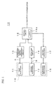
- Figure 1 is a block diagram showing an apparatus for discriminating an optical recording medium that is a preferred embodiment of the present invention.
- an apparatus 10 for discriminating an optical recording medium that is a preferred embodiment of the present invention includes a first electrode 11, a second electrode 12, an alternating current signal generation circuit 13 for applying an alternating current signal A to the first electrode 11, a detection circuit 14 for detecting the level of an alternating current signal B appearing at the second electrode 12, a supporting mechanism 16 for supporting the first electrode 11 and the second electrode 12, a driving mechanism 17 for vertically moving the supporting mechanism 16, and a control circuit 15 for controlling the operations of the alternating current signal generation circuit 13 and the detection circuit 14 and the driving mechanism 17.
- a table 15a is provided in the control circuit 15 and a detecting section 18 is constituted by the first electrode 11, the second electrode 12 and the supporting mechanism 16 for supporting the first electrode 11 and the second electrode 12.
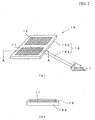
- Figure 2 is a diagram showing the structure of the detecting section 18, wherein Figure 2 (a) is a schematic perspective view showing the detecting section 18 and Figure (b) is a schematic cross-sectional view taken along a line A-A in Figure 2 (a).
- the supporting mechanism 16 is constituted by an arm 16a adapted to be vertically moved by the driving mechanism 17 and a plate-like electrode mounting section 16b provided at the tip end portion of the arm 16a.
- the first electrode 11 and the second electrode 12 are mounted on the electrode mounting section 16b and, as shown in Figure 2 (b), the surfaces of the first electrode 11 and the second electrode 12 are covered with a protective layer 19. !
- the protective layer 19 serves to prevent the first electrode 11 and the second electrode 12 from being corroded and also prevent the first electrode 11 and the second electrode 12 from coming into contact with a recording surface of an optical recording medium, thereby preventing the recording surface of the optical recording medium from being damaged by the first electrode 11 and the second electrode 12.
- the protective layer 19 it is necessary for the protective layer 19 to be formed of a material having good moisture-resistant property, good surface lubricating property, rubber elasticity, lower hardness than that forming a recording surface of an optical recording medium, good heat resistant property, good chemical resistant property and good molding property, and it is preferable to form the protective layer 19 of thermoplastic polyether ester elastomer, silicon resin, fluorocarbon resin or the like.
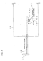
- Figure 3 is a schematic cross-sectional view showing a main body of a drive.
- the detecting section 18 having the above described configuration is disposed at such position that it can be brought into contact with one surface of an optical recording medium by accommodating the tray 41 on which the optical recording medium is placed in the main body 40 of the drive and actuating the driving mechanism 17.
- Figure 4 is a set of schematic cross-sectional views showing various kinds of optical recording media, wherein Figure 4 (a) is a schematic cross-sectional view showing a CD type optical recording medium, Figure 4 (b) is a schematic cross-sectional view showing a DVD type optical recording medium and Figure 4 (c) is a schematic cross-sectional view showing a next-generation type optical recording medium.
- a CD type optical recording medium 20a includes a substrate 21a, a recording layer 22a formed on the substrate 21a, a reflective layer 23a formed on the recording layer 22a and a protective layer 24a formed on the reflective layer 23a, and the central portion of thereof is formed with a hole 25a.
- a laser beam L20a having a wavelength ⁇ of 780 nm is projected thereonto from the side of the substrate 21a, thereby recording data therein and reproducing recorded therein.
- the substrate 21a serves to ensure the mechanical strength required by the optical recording medium 20a and an optical path for a laser beam L20a is formed therein.
- the optical recording medium 20a is to be constituted as a write-once optical recording medium (CD-R) or a data rewritable type optical recording medium (CD-RW)
- CD-R write-once optical recording medium
- CD-RW data rewritable type optical recording medium
- grooves and/or lands are formed on the surface of the substrate 21a.
- the grooves and/or lands serve as a guide track for the laser beam L20a when data are to be recorded or when data are to be reproduced.
- the substrate 21a has a thickness of about 1.1 mm and is normally formed of polycarbonate resin.
- the optical recording medium 20a is to be constituted as a write-once optical recording medium (CD-R) or a data rewritable type optical recording medium (CD-RW), the recording layer 22a is formed.
- CD-R write-once optical recording medium
- CD-RW data rewritable type optical recording medium
- the recording layer 22a is formed of organic dye and in the case where the optical recording medium 20a is constituted as a data rewritable type optical recording medium (CD-RW), the recording layer 22a is constituted by a phase change film and dielectric films sandwiching the phase change film.
- a write-once type optical recording medium data are recorded in the recording layer 22a by transforming a predetermined region of organic dye contained in the recording layer 22a.
- data rewritable type optical recording medium data are recorded in the recording layer 22a by changing the phase of the phase change film contained in the recording layer 22a between a crystalline state and an amorphous state.
- the optical recording medium 20a is constituted as a ROM type optical recording medium (CD-ROM)
- no recording layer 22a is formed and data are recorded by pre-pits (not shown) formed on the surface of the substrate 21a when the optical recording medium 20a is fabricated.
- the reflective layer 23a serves to reflect the laser beam L20a entering via the substrate 21a so as to emit it from the substrate 21a and is formed so as to have a thickness of 10 to 300 nm.
- the reflective layer 23a is formed of metal such as aluminum, silver or the like in order to effectively reflect the laser beam L20a.
- a layer such as a reflective layer 23a having conductivity is sometimes referred to as "a conductive layer.”
- the optical recording medium 20a is constituted as a data rewritable type optical recording medium (CD-RW)
- CD-RW data rewritable type optical recording medium
- the protective layer 24a serves to physically and chemically protect the recording layer 22a.
- the protective layer 24a is formed of ultraviolet ray curable resin or the like so as to have a thickness of about 100 ⁇ m.
- the distance between the surface of the substrate 21a through with the laser beam L20a enters and the reflective layer 23a or the recording layer 22a serving as a conductive layer is determined to be about 1.1 mm.
- the DVD type optical recording medium 20b includes a first substrate 21b, a recording layer 22b formed on the first substrate 21b, a reflective layer 23b formed on the recording layer 22b, an adhesive layer 28b formed on the reflective layer 23b and a second substrate 26b formed on the adhesive layer 28b, and the central portion of thereof is formed with a hole 25b.
- a laser bream L20b having a wavelength ⁇ of 650 nm is projected thereonto from the side of the first substrate 21b, thereby recording data therein and reproducing recorded therein.
- the first substrate 21b serves to ensure the mechanical strength required by the optical recording medium 20b and the optical path of the laser beam L20b is formed therein.
- the optical recording medium 20b is to be constituted as a write-once optical recording medium (DVD-R) or a data rewritable type optical recording medium (DVD-RW)
- DVD-R write-once optical recording medium
- DVD-RW data rewritable type optical recording medium
- grooves and/or lands are formed on the surface of the first substrate 21b.
- the grooves and/or lands serve as a guide track for the laser beam L20b when data are to be recorded or when data are to be reproduced.
- the second substrate 26b corresponds to the protective layer 24a in the CD type optical recording medium 20a.
- Each of the first substrate 21b and the second substrate 26b has a thickness of about 1.1 mm and is normally formed of polycarbonate resin.
- the recording layer 22b is formed in the case where the optical recording medium 20b is to be constituted as a write-once optical recording medium (DVD-R) or a data rewritable type optical recording medium (DVD-RW).
- DVD-R write-once optical recording medium
- DVD-RW data rewritable type optical recording medium
- the recording layer 22b is formed of organic dye and in the case where the optical recording medium 20b is constituted as a data rewritable type optical recording medium (DVD-RW), the recording layer 22b is constituted by a phase change film and dielectric films sandwiching the phase change film.
- the optical recording medium 20b is constituted as a ROM type optical recording medium (DVD-ROM)
- no recording layer 22b is formed and data are recorded by pre-pits (not shown) formed on the surface of the first substrate 21b when the optical recording medium 20b is fabricated.
- the reflective layer 23b serves to reflect the laser beam L20b entering via the first substrate 21b so as to emit it from the first substrate 21b and is formed so as to have a thickness of 10 to 300 nm.
- the reflective layer 23b is formed of metal such as aluminum, silver or the like in order to effectively reflect the laser beam L20b.
- the distance between the surface of the first substrate 21b through with the laser beam L20b enters and the reflective layer 23b or the recording layer 22b serving as a conductive layer is determined to be about 0.6 mm.
- the next-generation type optical recording medium 20c includes a substrate 21c, a reflective layer 23c formed on the substrate 21c, a recording layer 22c formed on the reflective layer 23c and a light transmission layer 27c formed on the recording layer 22c, and the central portion of thereof is formed with a hole 25c.
- a laser bream L20c having a wavelength ⁇ of about 400 nm is projected thereonto from the side of the light transmission layer 27c located on the opposite side from the substrate 21c, thereby recording data therein and reproducing recorded therein.
- the substrate 21c serves to ensure the mechanical strength required for the optical recording medium 20c and in the case where the optical recording medium 20c is to be constituted as a write-once optical recording medium or a data rewritable type optical recording medium, grooves and/or lands are formed on the surface of the substrate 21c.
- next-generation type optical recording medium 20c no optical path of the laser beam L20c is formed in the substrate 21c.
- the substrate 21c has a thickness of about 1.1 mm and is normally formed of polycarbonate resin.
- the reflective layer 23c serves to reflect the laser beam L20c entering via the light transmission layer 27c so as to emit it from the light transmission layer 27c and is formed so as to have a thickness of 10 to 300 nm.
- the reflective layer 23c is formed of metal such as aluminum, silver or the like in order to effectively reflect the laser beam L20c.
- the recording layer 22c is formed in the case where the optical recording medium 20c is to be constituted as a write-once optical recording medium or a data rewritable type optical recording medium.
- the optical recording medium 20c is constituted as a ROM type optical recording medium
- no recording layer 22c is formed and data are recorded by pre-pits (not shown) formed on the surface of the substrate 21c when the optical recording medium 20c is fabricated.
- the light transmission layer 27c is a layer in which the optical path of the laser beam L20c is formed.
- the thickness of the light transmission layer 27c depends upon the kind of the next-generation type optical recording medium 20c, the light transmission layer 27c is formed so as to have a thickness of about 10 to 300 ⁇ m.
- the material preferably used for forming the light transmission layer 27c depends upon the kind of the next-generation type optical recording medium 20c, a dielectric material such as ultraviolet ray curable resin, polycarbonate, polyolefin or the like is normally employed.
- the distance between the surface of the light transmission layer 27c through with the laser beam L20c enters and the reflective layer 23c serving a conductive layer is determined to be about 10 to 300 ⁇ m.
- the distance between the surface of the light transmission layer 27c through with the laser beam L20c enters and the recording layer 22c which is a conductive layer closest to the light transmission layer 27c is determined to be slightly shorter than the distance between the surface of the light transmission layer 27c and the reflective layer 23c.
- the apparatus 10 for discriminating an optical recording medium shown in Figures 1 to 3 discriminates the kind of an optical recording medium 20 among the optical recording media having different structures in the above described manner as follows.
- Figure 5 is a flow chart of a method for discriminating an optical recording medium using the apparatus 10 for discriminating an optical recording medium.
- the tray 41 of the drive is discharged from the main body 40 of the drive (Step S1) and an optical recording medium 20 is placed on the tray 41 by the user (Step S2).
- the tray 41 is then accommodated in the main body 40 of the drive (Step S3) and correspondingly, the detecting section 18 is moved upward in Figure 3 by the driving mechanism 17 under the control of the control circuit 15 until the protective layer 19 comes into contact with the light incidence plane of the optical recording medium 20 (Step S4).
- the surface of the protective layer 19 has good lubricating property, the light incidence plane of the optical recording medium 20 is not damaged when the protective layer 19 comes into contact with the light incidence plane of the optical recording medium 20.
- the distance between the first electrode 11 and second electrode 12 and the reflective layer 23 or recording layer 22, which is a conductive layer becomes equal to (1.1 mm + thickness of the protective layer 19) and in the case where the optical recording medium 20 placed on the tray 41 is a DVD type optical recording medium 20b, the distance between the first electrode 11 and second electrode 12 and the reflective layer 23 or recording layer 22, which is a conductive layer, becomes equal to (0.6 mm + thickness of the protective layer 19).
- the distance between the first electrode 11 and second electrode 12 and the reflective layer 23 or recording layer 22, which is a conductive layer becomes equal to (10 to 300 ⁇ m + thickness of the protective layer 19).
- C1 is a capacitance component constituted by the first electrode 11, the reflective layer 23 or the recording layer 22 and a dielectric material present between the first electrode 11 and the reflective layer 23 or the recording layer 22
- C2 is a capacitance component constituted by the second electrode 12, the reflective layer 23 or the recording layer 22 and a dielectric material present between the second electrode 12 and the reflective layer 23 or the recording layer 22.
- C1 C2.
- the values of the capacitance components C1 and C2 are determined depending upon the thickness and dielectric constant of the dielectric material present between the first electrode 11 and second electrode 12 and the reflective layer 23 or recording layer 22.
- the optical recording medium 20 placed on the tray 41 is a CD type optical recording medium 20a
- the optical recording medium 20 placed on the tray 41 is a next-generation type optical recording medium 20c
- an alternating current signal A generated by the alternating current signal generation circuit 13 is applied to the first electrode 11 under the control of the control circuit 15 while the detecting section 18 is in contact with the light incidence plane of the optical recording medium 20 (Step S5).
- the alternating current signal B appearing at the second electrode 12 is detected by the detection circuit 14 and the control circuit 15 discriminates the kind of the optical recording medium 20 placed on the tray 41 based on the alternating current signal B detected by the detection circuit 14 (Step S6).
- the control circuit 15 discriminates that the optical recording medium 20 placed on the tray 41 is a CD type optical recording medium 20a and in the case where the level of the alternating current signal B is equal to that obtained when the values of the capacitance components C1 and C2 are equal to Cb, the control circuit 15 discriminates that the optical recording medium 20 placed on the tray 41 is a DVD type optical recording medium 20b.
- the control circuit 15 discriminates that the optical recording medium 20 placed on the tray 41 is a next-generation type optical recording medium 20c.
- the kind of optical recording media 20 can be discriminated by referring to the table 15a in the control circuit 15.
- the detecting section 18 is moved downward in Figure 3 by the driving mechanism 17 under the control of the control circuit 15 so that the detecting section 18 is moved away from the light incidence plane of the optical recording medium 20 (Step S7).
- Step S8 the optical recording medium 20 is rotated by a spindle motor (not shown) (Step S8) and a laser component and an optical system corresponding to the kind of the optical recording medium 20 discriminated at Step S6 are selected, thereby emitting a laser beam Step S9).
- the apparatus for discriminating an optical recording medium according to this embodiment is mounted on a data recording and reproducing apparatus (drive), it is possible to immediately discriminate the kind of an optical recording medium 20 set in the data recording and reproducing apparatus prior to projecting a laser beam thereon.
- the kind of an optical recording medium 20 is discriminated while the detecting section 18 is in contact with the surface of the optical recording medium 20, even in the case where an optical recording medium 20 to be discriminated is warped, it is possible to accurately discriminate the kind of the optical recording medium 20 without being affected by the warpage of the optical recording medium 20.
- an optical recording medium 20 even in the case where change in a detection signal caused by the warpage of an optical recording medium 20 greatly affects the results of discrimination of the kind of an optical recording medium 20 such as when discriminating a DVD in which data are to be recorded in one layer on one side and a DVD in which data are to be recorded in two layers on one side, in which DVDs the difference in distance between the light incidence plane and a conductive layers such as a reflective layer is small, the kind of the optical recording medium 20 can nevertheless be accurately discriminated.
- the kind of an optical recording medium 20 is discriminated by applying an alternating current signal A generated by the alternating current signal generation circuit 13 to the first electrode 11 and detecting an alternating current signal B appearing at the second electrode 12 while the detecting section 18 is in contact with the surface of the optical recording medium 20, even in the case of discriminating the kinds of next-generation type optical recording media that differ only slightly in the thickness and material of the light transmission layers 27c so that the values of the capacitance components Cc are close to each other, the discrimination can be made without being affected by an air layer having a high dielectric constant. Therefore, it is possible to accurately discriminate the kind of a next-generation type optical recording medium 20 by detecting the level of an alternating current signal B appearing at the second electrode 12.
- the first electrode 11 and the second electrode 12 are covered with the protective layer having a good lubricating property, it is possible to reliably prevent damage to the light incidence plane of an optical recording medium 20 despite the fact that the protective layer comes into contact with the light incidence plane of the optical recording medium 20.
- the detecting section 18 is moved away from the surface of an optical recording medium 20 by the driving mechanism 17 after discriminating the kind of the optical recording medium and prior to rotating the optical recording medium 20 by the spindle motor, it is possible to reliably prevent the detecting section 18 from coming into contact with the surface of the optical recording medium 20 and damaging the optical recording medium 20 when the optical recording medium 20 is being rotated.
- Figure 8 is a schematic cross-sectional view showing one example of a method for mounting the apparatus 10 for discriminating an optical recording medium on a data recording and reproducing apparatus (drive), wherein Figure 8 (a) shows the state where the tray 41 is discharged from the main body 40 of the drive and Figure 8 (b) shows the state where the tray 41 is accommodated in the main body 40.
- the apparatus 10 for discriminating an optical recording medium is mounted on the data recording and reproducing apparatus (drive) in this manner, since it is possible to discriminate the kind of an optical recording medium 20 after placing the optical recording medium 20 on the tray 41 and prior to accommodating the tray 41 in the main body 40 of the drive, the time required for recording data in or reproducing data from the optical recording medium 20 after it is placed on the tray 41 can be considerably shortened.
- Figure 9 (a) is a schematic longitudinal cross-sectional view showing another example of a method for mounting the apparatus 10 for discriminating an optical recording medium according to this embodiment on a data recording and reproducing apparatus (drive) and Figure 9 (b) is a schematic cross-sectional view taken along a line A-A in Figure 9 (a).
- a first electrode 11 and a second electrode 12 are constituted by a shaft of a roller 43 of a slot-loading type data recording and reproducing apparatus (drive).
- the kind of an optical recording medium 20 is discriminated by employing the first electrode 11 and the second electrode 12 and detecting an alternating current signal B appearing at the second electrode 12 when an alternating current signal A is applied to the first electrode 11, it is possible to discriminate the kind of an optical recording medium 20 by employing a planar-coil like electrode and detecting an eddy current generated by supplying an electrical current to the planar-coil like electrode.
- the kind of an optical recording medium 20 is discriminated while the detecting section 18 is in contact with the light incidence plane of an optical recording medium 20
- optical recording media in which focus distances are different from each other are discriminated
- the present invention can be applied to the case where a plurality kinds of optical recording media for which a common recording and reproducing system is used, for example, a DVD in which data are to be recorded in one layer on one side and a DVD in which data are to be recorded in two layers on one side, are discriminated.
- an apparatus for discriminating an optical recording medium and a method for discriminating an optical recording medium which can reliably discriminate the kind of an optical recording medium.
- an apparatus for discriminating an optical recording medium and a method for discriminating an optical recording medium which can reliably discriminate the kind of an optical recording medium even in the case where the optical recording medium to be discriminated is warped.
Landscapes
- Optical Recording Or Reproduction (AREA)
- Optical Record Carriers And Manufacture Thereof (AREA)
Applications Claiming Priority (3)
| Application Number | Priority Date | Filing Date | Title |
|---|---|---|---|
| JP2002120419 | 2002-04-23 | ||
| JP2002120419A JP2003317238A (ja) | 2002-04-23 | 2002-04-23 | 光記録媒体判別装置及び光記録媒体判別方法 |
| PCT/JP2003/005181 WO2003091992A1 (en) | 2002-04-23 | 2003-04-23 | Optical recording medium judgment device and optical recording medium judgment method |
Publications (1)
| Publication Number | Publication Date |
|---|---|
| EP1515312A1 true EP1515312A1 (de) | 2005-03-16 |
Family
ID=29267369
Family Applications (1)
| Application Number | Title | Priority Date | Filing Date |
|---|---|---|---|
| EP03723179A Withdrawn EP1515312A1 (de) | 2002-04-23 | 2003-04-23 | Beurteilungseinrichtung und beurteilungsverfahren für ein optisches aufzeichnungsmedium |
Country Status (7)
| Country | Link |
|---|---|
| US (1) | US7085213B2 (de) |
| EP (1) | EP1515312A1 (de) |
| JP (1) | JP2003317238A (de) |
| CN (1) | CN1659629A (de) |
| AU (1) | AU2003235103A1 (de) |
| TW (1) | TW200307911A (de) |
| WO (1) | WO2003091992A1 (de) |
Families Citing this family (3)
| Publication number | Priority date | Publication date | Assignee | Title |
|---|---|---|---|---|
| WO2007096919A1 (en) * | 2006-02-27 | 2007-08-30 | Stmicroelectronics S.R.L. | Read/write transducer for a ferroelectric storage medium, and corresponding storage device and method |
| WO2007113878A1 (en) * | 2006-04-06 | 2007-10-11 | Stmicroelectronics S.R.L. | Process for manufacturing an interaction structure for a storage medium |
| WO2009116769A1 (en) | 2008-03-17 | 2009-09-24 | Lg Electronics Inc. | Method of transmitting reference signal and transmitter using the same |
Family Cites Families (9)
| Publication number | Priority date | Publication date | Assignee | Title |
|---|---|---|---|---|
| JPS5215062A (en) * | 1975-07-25 | 1977-02-04 | Tsubakimoto Kogyo Kk | Transfer apparatus of member having center hole |
| JPS5629816Y2 (de) * | 1976-05-06 | 1981-07-15 | ||
| JPS6025815B2 (ja) | 1976-06-09 | 1985-06-20 | パイオニア株式会社 | デイスクプレ−ヤ |
| JP2794348B2 (ja) * | 1991-06-21 | 1998-09-03 | キヤノン株式会社 | 記録媒体、その製造方法、情報処理装置 |
| JP2994505B2 (ja) * | 1991-10-04 | 1999-12-27 | キヤノン株式会社 | 情報再生装置 |
| JPH10143A (ja) * | 1996-06-14 | 1998-01-06 | Kawajiyun Kk | 陳列棚用仕切板 |
| JPH1055601A (ja) | 1996-08-09 | 1998-02-24 | Kenwood Corp | 光ディスク装置のディスク判別装置 |
| JPH10143986A (ja) | 1996-11-01 | 1998-05-29 | Toshiba Corp | 光ディスク判別装置 |
| EP1128368B1 (de) * | 1998-09-10 | 2007-08-29 | Matsushita Electric Industrial Co., Ltd. | Optisches informationsaufzeichnungsmedium, verfahren zur herstellung, und verfahren zur aufzeichnung und wiedergabe |
-
2002
- 2002-04-23 JP JP2002120419A patent/JP2003317238A/ja not_active Withdrawn
-
2003
- 2003-04-23 AU AU2003235103A patent/AU2003235103A1/en not_active Abandoned
- 2003-04-23 EP EP03723179A patent/EP1515312A1/de not_active Withdrawn
- 2003-04-23 CN CN038132257A patent/CN1659629A/zh active Pending
- 2003-04-23 US US10/512,211 patent/US7085213B2/en not_active Expired - Fee Related
- 2003-04-23 WO PCT/JP2003/005181 patent/WO2003091992A1/ja not_active Ceased
- 2003-04-23 TW TW092109493A patent/TW200307911A/zh unknown
Non-Patent Citations (1)
| Title |
|---|
| See references of WO03091992A1 * |
Also Published As
| Publication number | Publication date |
|---|---|
| US20050152249A1 (en) | 2005-07-14 |
| JP2003317238A (ja) | 2003-11-07 |
| US7085213B2 (en) | 2006-08-01 |
| WO2003091992A1 (en) | 2003-11-06 |
| CN1659629A (zh) | 2005-08-24 |
| AU2003235103A1 (en) | 2003-11-10 |
| TW200307911A (en) | 2003-12-16 |
Similar Documents
| Publication | Publication Date | Title |
|---|---|---|
| EP1777702B1 (de) | Optisches Informationsaufzeichnungsmedium, Verfahren und Gerät zur Aufzeichnung und Wiedergabe | |
| KR0183172B1 (ko) | 복층 디스크 포커싱 장치 및 방법 | |
| JP2000311427A (ja) | ディスク判別方法および装置 | |
| US7085213B2 (en) | Apparatus for discriminating optical recording medium and method for discriminating optical recording medium | |
| KR100470027B1 (ko) | 반사표면을 갖는 고밀도 광디스크 및 그 구동방법 | |
| US7158459B2 (en) | Apparatus for discriminating optical recording medium and method for discriminating optical recording medium | |
| US7266065B2 (en) | Apparatus for discriminating optical recording medium and method for discriminating optical recording medium | |
| EP1501083A1 (de) | Diskriminationseinrichtung für ein optisches aufzeichnungsmedium und diskriminationsverfahren für ein optisches aufzeichnungsmedium | |
| US7724622B2 (en) | Recording device capable of determining the media type based on detecting the capacitance of pair electrodes | |
| US7200084B2 (en) | Apparatus for discriminating optical recording medium and method for discriminating optical recording medium | |
| EP1488419B1 (de) | Servosteuerungsverfahren einer optischen plattenvorrichtung | |
| JP2003233912A (ja) | 光ディスク装置 | |
| JP4067536B2 (ja) | 光ディスク装置およびディスク判別方法 | |
| KR20040024014A (ko) | 고밀도 광디스크와 그에 따른 구동방법 | |
| CN101645277A (zh) | 光盘装置及具有其的光盘处理系统 | |
| JP2008010060A (ja) | 光記録媒体、ピックアップ装置およびドライブ装置 | |
| JPH1011884A (ja) | ディスク判別方法及び装置 | |
| JPH09282717A (ja) | 光ディスク及び光ディスク装置 |
Legal Events
| Date | Code | Title | Description |
|---|---|---|---|
| PUAI | Public reference made under article 153(3) epc to a published international application that has entered the european phase |
Free format text: ORIGINAL CODE: 0009012 |
|
| 17P | Request for examination filed |
Effective date: 20041111 |
|
| AK | Designated contracting states |
Kind code of ref document: A1 Designated state(s): AT BE BG CH CY CZ DE DK EE ES FI FR GB GR HU IE IT LI LU MC NL PT RO SE SI SK TR |
|
| STAA | Information on the status of an ep patent application or granted ep patent |
Free format text: STATUS: THE APPLICATION HAS BEEN WITHDRAWN |
|
| 18W | Application withdrawn |
Effective date: 20051222 |