EP1514821A2 - Leitwalze zur Führung einer Materialbahn - Google Patents
Leitwalze zur Führung einer Materialbahn Download PDFInfo
- Publication number
- EP1514821A2 EP1514821A2 EP04106503A EP04106503A EP1514821A2 EP 1514821 A2 EP1514821 A2 EP 1514821A2 EP 04106503 A EP04106503 A EP 04106503A EP 04106503 A EP04106503 A EP 04106503A EP 1514821 A2 EP1514821 A2 EP 1514821A2
- Authority
- EP
- European Patent Office
- Prior art keywords
- guide roller
- piston
- web
- guide
- turning bar
- Prior art date
- Legal status (The legal status is an assumption and is not a legal conclusion. Google has not performed a legal analysis and makes no representation as to the accuracy of the status listed.)
- Withdrawn
Links
Images



Classifications
-
- B—PERFORMING OPERATIONS; TRANSPORTING
- B65—CONVEYING; PACKING; STORING; HANDLING THIN OR FILAMENTARY MATERIAL
- B65H—HANDLING THIN OR FILAMENTARY MATERIAL, e.g. SHEETS, WEBS, CABLES
- B65H43/00—Use of control, checking, or safety devices, e.g. automatic devices comprising an element for sensing a variable
- B65H43/08—Photoelectric devices
-
- B—PERFORMING OPERATIONS; TRANSPORTING
- B65—CONVEYING; PACKING; STORING; HANDLING THIN OR FILAMENTARY MATERIAL
- B65H—HANDLING THIN OR FILAMENTARY MATERIAL, e.g. SHEETS, WEBS, CABLES
- B65H23/00—Registering, tensioning, smoothing or guiding webs
- B65H23/02—Registering, tensioning, smoothing or guiding webs transversely
- B65H23/032—Controlling transverse register of web
-
- B—PERFORMING OPERATIONS; TRANSPORTING
- B65—CONVEYING; PACKING; STORING; HANDLING THIN OR FILAMENTARY MATERIAL
- B65H—HANDLING THIN OR FILAMENTARY MATERIAL, e.g. SHEETS, WEBS, CABLES
- B65H23/00—Registering, tensioning, smoothing or guiding webs
- B65H23/02—Registering, tensioning, smoothing or guiding webs transversely
- B65H23/032—Controlling transverse register of web
- B65H23/035—Controlling transverse register of web by guide bars
-
- B—PERFORMING OPERATIONS; TRANSPORTING
- B65—CONVEYING; PACKING; STORING; HANDLING THIN OR FILAMENTARY MATERIAL
- B65H—HANDLING THIN OR FILAMENTARY MATERIAL, e.g. SHEETS, WEBS, CABLES
- B65H23/00—Registering, tensioning, smoothing or guiding webs
- B65H23/04—Registering, tensioning, smoothing or guiding webs longitudinally
- B65H23/24—Registering, tensioning, smoothing or guiding webs longitudinally by fluid action, e.g. to retard the running web
-
- B—PERFORMING OPERATIONS; TRANSPORTING
- B65—CONVEYING; PACKING; STORING; HANDLING THIN OR FILAMENTARY MATERIAL
- B65H—HANDLING THIN OR FILAMENTARY MATERIAL, e.g. SHEETS, WEBS, CABLES
- B65H23/00—Registering, tensioning, smoothing or guiding webs
- B65H23/04—Registering, tensioning, smoothing or guiding webs longitudinally
- B65H23/32—Arrangements for turning or reversing webs
-
- B—PERFORMING OPERATIONS; TRANSPORTING
- B65—CONVEYING; PACKING; STORING; HANDLING THIN OR FILAMENTARY MATERIAL
- B65H—HANDLING THIN OR FILAMENTARY MATERIAL, e.g. SHEETS, WEBS, CABLES
- B65H2406/00—Means using fluid
- B65H2406/10—Means using fluid made only for exhausting gaseous medium
- B65H2406/11—Means using fluid made only for exhausting gaseous medium producing fluidised bed
- B65H2406/111—Means using fluid made only for exhausting gaseous medium producing fluidised bed for handling material along a curved path, e.g. fluidised turning bar
-
- B—PERFORMING OPERATIONS; TRANSPORTING
- B65—CONVEYING; PACKING; STORING; HANDLING THIN OR FILAMENTARY MATERIAL
- B65H—HANDLING THIN OR FILAMENTARY MATERIAL, e.g. SHEETS, WEBS, CABLES
- B65H2406/00—Means using fluid
- B65H2406/10—Means using fluid made only for exhausting gaseous medium
- B65H2406/11—Means using fluid made only for exhausting gaseous medium producing fluidised bed
- B65H2406/111—Means using fluid made only for exhausting gaseous medium producing fluidised bed for handling material along a curved path, e.g. fluidised turning bar
- B65H2406/1115—Means using fluid made only for exhausting gaseous medium producing fluidised bed for handling material along a curved path, e.g. fluidised turning bar pivoting around an axis perpendicular to the axis of the guided material
-
- B—PERFORMING OPERATIONS; TRANSPORTING
- B65—CONVEYING; PACKING; STORING; HANDLING THIN OR FILAMENTARY MATERIAL
- B65H—HANDLING THIN OR FILAMENTARY MATERIAL, e.g. SHEETS, WEBS, CABLES
- B65H2406/00—Means using fluid
- B65H2406/10—Means using fluid made only for exhausting gaseous medium
- B65H2406/14—Means using fluid made only for exhausting gaseous medium with selectively operated air supply openings
-
- Y—GENERAL TAGGING OF NEW TECHNOLOGICAL DEVELOPMENTS; GENERAL TAGGING OF CROSS-SECTIONAL TECHNOLOGIES SPANNING OVER SEVERAL SECTIONS OF THE IPC; TECHNICAL SUBJECTS COVERED BY FORMER USPC CROSS-REFERENCE ART COLLECTIONS [XRACs] AND DIGESTS
- Y10—TECHNICAL SUBJECTS COVERED BY FORMER USPC
- Y10T—TECHNICAL SUBJECTS COVERED BY FORMER US CLASSIFICATION
- Y10T83/00—Cutting
- Y10T83/202—With product handling means
- Y10T83/2066—By fluid current
- Y10T83/2068—Plural blasts directed against plural product pieces
-
- Y—GENERAL TAGGING OF NEW TECHNOLOGICAL DEVELOPMENTS; GENERAL TAGGING OF CROSS-SECTIONAL TECHNOLOGIES SPANNING OVER SEVERAL SECTIONS OF THE IPC; TECHNICAL SUBJECTS COVERED BY FORMER USPC CROSS-REFERENCE ART COLLECTIONS [XRACs] AND DIGESTS
- Y10—TECHNICAL SUBJECTS COVERED BY FORMER USPC
- Y10T—TECHNICAL SUBJECTS COVERED BY FORMER US CLASSIFICATION
- Y10T83/00—Cutting
- Y10T83/202—With product handling means
- Y10T83/2092—Means to move, guide, or permit free fall or flight of product
- Y10T83/2209—Guide
-
- Y—GENERAL TAGGING OF NEW TECHNOLOGICAL DEVELOPMENTS; GENERAL TAGGING OF CROSS-SECTIONAL TECHNOLOGIES SPANNING OVER SEVERAL SECTIONS OF THE IPC; TECHNICAL SUBJECTS COVERED BY FORMER USPC CROSS-REFERENCE ART COLLECTIONS [XRACs] AND DIGESTS
- Y10—TECHNICAL SUBJECTS COVERED BY FORMER USPC
- Y10T—TECHNICAL SUBJECTS COVERED BY FORMER US CLASSIFICATION
- Y10T83/00—Cutting
- Y10T83/647—With means to convey work relative to tool station
- Y10T83/6584—Cut made parallel to direction of and during work movement
- Y10T83/6587—Including plural, laterally spaced tools
- Y10T83/6588—Tools mounted on common tool support
Definitions
- the invention relates to a guide roller for guiding a material web according to the Preamble of claim 1.
- Guide rollers of this type are used in particular at the exit of a rotary printing machine used, if applicable, several partial webs, in which one of the Rotary printing machine printed paper web has been cut, and the lying side by side leave a cutting device, so to redirect that they one above the other, possibly folded and further processed.
- DE 34 36 870 C1 discloses a turning bar with axially displaceable piston.
- turner bars are known which with a compressed air-supplied interior are formed.
- the coat of the turning bar is on At least a part of its circumference provided with holes, through the air from the Interior space can escape to an air cushion between the turning bar and the To form material web.
- pistons are used, which at their the interior facing side are not plan, but have edges, their course respectively one half of its scope to a right-handed and the other half to one corresponds to left-handed helix.
- the pistons are in the turning bar around their Rotatable axis, so that, depending on which direction the material web is deflected, one or the other of the two helical edges to the perforated Part of the circumference of the shell can be turned out, which is to be deflected by the Material web is entwined.
- JP 11-246098 A describes a loadable with air guide roll whose coat with Holes is provided. These holes are hydraulic by means of one in the interior slidable locking element depending on a web width selectively closed. For detecting the web width sensors are arranged.
- the invention is based on the object, a guide roller for guiding a web to accomplish.
- the achievable with the present invention consist in particular that a Adjustment of the position of the piston to the width or the position of a material web the guide roller can be done quickly and selectively. Even an adjustment of the position of Piston to a web displacement while the web is running is readily possible.
- Control signal for the control circuit come in particular two types of signals
- a quantitative signal d. H. a signal with a numerical value can be assigned and that allows the control circuit, the engine so long to operate until the piston has reached a position corresponding to the numerical value
- a signal with at least two discrete states one of which as can be called “forbidden” and the other as “allowed” state, in which case the controller may be to operate the engine until the signal in goes over the "allowed” state.
- the first type of control signal is particularly suitable for attaching it to one of the guide rollers upstream, the web-processing device such as a Tapping tool, whether by measuring the position of a device, the determines the position of a web edge or directly by deriving from a control signal, which determines the position of such a device.
- the web-processing device such as a Tapping tool
- the position of an edge of the material web by means of a sensor directly determine or that the target value from a memory device z. Eg control room is given.
- a control signal of the second type can preferably by means of a to the respective Position of the piston coupled movable detector to detect the position of the Web edge are generated.
- the coupling can be a mechanical connection between piston and detector include; but it comes, especially if the Detector of the guide roller is arranged on the path of the material web, a control technology coupling into consideration.
- the quick and targeted adaptability of the piston position is particularly important in a pivotable guide roll, the deflection of the web optionally in two different directions allowed.
- the process of positioning the piston can be so be fully automated, making the switch to different web widths and optionally deflection directions further simplified.
- Another advantage is that after a pivoting of the guide roller a separate Operation of turning the pistons to adapt their edge profile to the Course of the web edges deleted.
- the air pressure of the interior against the edges of the slot pressed sealing tape can advantageously be provided.
- the latter is preferably coupled to the piston and before the Slidable.
- the detector may also be within the piston for detecting presence or absence of the web of material in front of one of the holes.
- the guide roller can be pivoted by 90 ° about an axis perpendicular to its longitudinal axis is to redirect a web optionally in opposite directions, so describe the edges of the material web on the surface of the guide roller depending on Direction of turning a left-handed or a right-handed helix.
- a axial rotation of the piston can always be that portion of the piston edge whose Direction of rotation corresponds to the web edge, with the perforated peripheral region of the Mantels are brought into contact so as to coincide with the course of the web edge congruent course of the edge of the piston to achieve.
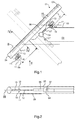
- turning bar 01 is a cylindrical Hollow body, by a on his coat 02 approximately centrally acting arm 03 connected to a frame (not shown).
- the support arm 03 has a hinge 04, a pivoting movement of the turning bar 01 to one to the plane of Fig. 1st vertical axis by an angle of 90 ° permits.
- the turning bar 01 is with the Joint 04 connected by a connector 06, which in the end positions of Pivoting freedom of the turning bar 01 each to one of two attacks 07 of the support arm 03 abuts.
- the stops 07 are each adjustable in length to the Freedom of movement of the turning bar 01 to adjust to exactly 90 °.
- the joint 04 and the connector 06 runs a Compressed air supply line (not shown) through which an interior of the turning bar 01 with Compressed air is supplied.
- This interior is on the one hand by the jacket 02 and the other by two in the shell 02 axially displaceable locking elements, z. B. piston 17th limited, the structure of which will be discussed in more detail later with reference to FIG.
- the Jacket 02 is on the side facing away from the connector 06 half of its circumference a regular array of holes 08 provided by the compressed air from the Interior can leak to an air cushion for one on the turning bar 01 to form deflected web of material 09.
- This material web 09 is transparent in FIG. 1 drawn, their edges 11 are shown as dashed lines.
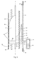
- FIG. 2 shows a view of the turning bar 01 in the direction of the arrow II of Fig. 1.
- the detector holder 14 and 15 with a the two previously mentioned piston 17 connects inside the turning bar 01.
- the Detector holder 14 here has the shape of a frame with a slot in which a Detector unit of two photocells 16 parallel to the longitudinal axis of the turning bar 01 is held adjustable. As can be seen in Fig.
- one of the two photocells 16 is after above, the other oriented downwards.
- Fig. 1 detects the after bottom oriented photocell 16 of the detector holder 15 an edge 11 of the expiring Material web 09.
- the upwardly oriented photocell 16 in the detector holder 14 detects a Edge 11 of the incoming material web 09.
- Fig. 3 is a partial section through the turning bar 01 of FIG. 1 in which in Fig. 1 with III marked area.
- This partial section shows a part of the internal structure of the Turning bar 01 and in particular one of the two axially displaceable piston 17th
- the plane of the section is indicated by the dot-dashed line in FIG. 2 specified. It can be seen in the section clearly the holes 08 and the slot 12 in Coat 02 of the turning bar 01.
- the piston 17 is in Fig. 3, left of the longitudinal axis X-X of the turning bar 01 in Top view and right of the longitudinal axis shown in section. He's about the shape a cup with a bottom 18 and a side wall 19, whose the interior 21st facing edge by two helical sections 22; 23 with each opposite direction of rotation is formed. In the position of the piston 17 shown here has the holes 08 facing portion 22 a right-handed and the Slot 12 facing portion 23 a left-handed direction of rotation.
- edge portion 22 is exactly parallel to an in the position shown in Fig. 1 the turning bar 01 to this looped web edge 11.
- a threaded spindle 24 which is threaded in the bottom 18 of the piston 17 is engaged and of a shown in Fig. 5 in more detail Adjusting means, for. B.
- Motor 36 is rotated.
- a second, by the same engine 36 rotatably driven threaded spindle 26 passes through a threaded opening without an opening in Bottom 18. It engages with a thread in the bottom 18 of an analogous to the piston 17 formed second piston 17, the piston 17 diametrically opposite in the turning bar 01 is housed.
- a rod 27 with a square cross-section extends along the axis X-X and with slight play through an opening in the bottoms 18 of both pistons 17. It is equipped with a in Fig. 6 shown gear 44, 46, 27 fixedly connected and serves to rotate the piston 17 about the axis X-X in the event of pivoting of the turning bar 01 between their two stop positions.
- annular groove 28 is formed in the side wall 19, in which a Ring 29 is rotatable.
- the ring 29 is fixedly connected to the already mentioned rod 13, where the detector holder 14 is disposed. Through the ring 29, it is possible to To rotate the piston 17 about the axis X-X without the detector holder 14 this Must follow rotational movement.
- a sealing strip 31 is also added, the extends over the entire length 21 of the slot 12 open towards the interior.
- Fig. 4 shows this arrangement in a section at the level of line IV-IV in Fig. 1.
- the Sealing strip 31 is in its entire thickness in grooves 32 on both sides of the Slit 12 is inserted so that it does not affect the rotation of the piston 17.
- a bracket 33 may at the connector 06 facing the end of the slot 12th be attached, the sealing strip 31 in a non-pressurized Condition of the interior 21 keeps pressed against the jacket 02 and so ensures that this unfolds its sealing effect when compressed air is placed in the interior 21 becomes.
- Fig. 5 shows a section along the longitudinal axis X-X of the turning bar 01 through the in Fig. 1 with 34 designated end portion 34.
- end portion 34 is the already mentioned engine 36 housed in a chamber, which in the direction of the piston 17 back (Upwards in Fig. 5) is limited by a plate 37.
- the plate 37 is using a Rolling bearing 38 rotatably held in the shell 02.
- the rod 27 is connected to the plate 37 rotatably engaged.
- the threaded spindles 24; 26 are rotatable by the plate 37 carried out and contribute at their ends in the interior of the chamber respectively Drive wheel 39; 41.
- One to the drive wheels 39; 41 complementary wheel 42 is at the Drive shaft 43 of the motor 36 mounted.
- the drive shaft 43 is in the direction of Longitudinal axis X-X displaceable between the position shown in Fig. 5, in which the wheel 42 with the drive wheel 39 is engaged, and an engaged position with the drive wheel 41st
- the motor 36 can thus optionally used to displace both pistons 17.
- the wheels 39; 41; 42 can Friction wheels or gears; to facilitate the intervention of the wheels into each other, the drive wheels 39; 41 frusto-conical and the wheel 42 be formed double frustoconical.
- This motor can be arranged stationary or so that it is a rotational movement of the Rod follows.
- Fig. 6 shows a transmission for driving a 180 ° rotation of the piston 17 in the case of Pivoting movement of the turning bar 01 from one of its working positions to the other.
- the reference numeral 44 denotes a section of a gear or Gear segment, which is housed in the connector 06. This gear or gear segment 44 may be arranged stationarily in the connector 06, it However, could also be coupled to the position of the turning bar 01 such that it in the case of a pivoting movement of the turning bar 01 performs a self-rotation.
- This gear or gear segment 44 meshes via a helical toothing with a another gear 46 which is rotatable about the longitudinal axis X-X of the turning bar 01 and that is the free cross section of the interior 21 of the turning bar 01 substantially fills.
- This gear 46 is in Fig. 6 to the left of the longitudinal axis X-X in section and shown to the right of the axis in plan view. It is firmly connected to the rod 27.
- the Threaded spindle 26, which is used to drive the piston 17 to that of the motor 36th facing away from the turning bar 01 is through a bore of the gear 46th freely rotatably guided.
- the threaded spindle 24, which is used to drive the motor 36 adjacent piston 17 is rotatably supported in the gear 46.
- the gear or gear segment 44 and the gear 46 are designed so that they have a Pivoting movement of the turning bar 01 by 90 ° about the axis of the joint 04 in one 180 ° rotation of the gear 46 and thus the piston 17 implement. That's how it works shown in Fig. 6 gear 44, 46, 27, that the piston 17 in each of the two Working positions of the turning bar 01 in each adapted thereto Drehorientmaschine are located.
- the position of the detector unit in the detector holders 14, 15 corresponds at the moment when the detector unit registers a web edge 11, the Position of the outside of the shell 02 facing edge portion 22 or 23 of the Piston 17 exactly the course of the edge 11 of the web 09 on the turning bar 01.
- the two pistons 17 cut all those holes 08 on the shell 02 of the Turning bar 01 from the compressed air supply from the interior 21, which is not from the Material web 09 are covered; however, below the material web 09, a can full-surface, homogeneous air cushion can be generated.
- Fig. 7 shows a section through the end portion of a turning bar 01 according to a second embodiment of the invention.
- the position of the cut is the same as in FIG. 5.
- Elements that are in shape or function the elements of the above Embodiment correspond, are provided with the same reference numerals.
- the Plate 37 is rotatably connected here with the jacket 02, the rod 27 is rotatable on the Plate 37 stored.
- the motor 36 drives via the wheels 42; 39 only the spindle 26 of the one Piston 17 on; a corresponding engine for the other piston is located at another end of the turning bar 01.
- a through a slot 47 in the jacket 02nd engaging wheel 48 is engaged with the wheel 42; it transmits a turn of the Motors 36 held on a outside of the turning bar 01 parallel to this Threaded spindle 49.
- This threaded spindle 49 drives a (not shown in FIG. 7) Detector holder as the detector holder 14 of FIG. 1 at a to the movement of the Piston 17 coupled movement.
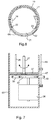
- Fig. 8 shows a third embodiment of the turning bar 01 in a cross section.
- the detectors With the detectors it can in turn, for example, to photocells 16 act.
- These photocells 16 are at the Embodiment of Fig. 8 arranged inside the turning bar 01, and indeed they are each in the side wall 19 of the cylinder 17 in each case in the vicinity of the edge portion 22; 23 so that they can detect the presence of the web 09, provided that Detectors are located in front of one of the holes 08.
- the detector is in particular also a flow sensor applicable, which registers the flow of air from the interior 21 to the outside, if he passes a hole 08 that is not covered by the web 09.
- Fig. 9 shows a schematic representation of turning bars 01 and their control.
- a plurality of turning bars 01, the z. B. following a cutter are arranged, in which a web of material 09, in particular a printed paper web 09, is cut into a plurality of partial webs 09, each of a Turning bar 01 are deflected.
- the position of the individual rotating blades 51 the cutting device is adjustable at a control station 54.
- This control signal which at the same time also the location the edges 11 of the section webs 09 cut by the knives 51 become defined a control circuit 53 is branched, the thereof taking into account the positions the - adjustable transverse to the web direction - turning bars 01 each have a desired position the cylinder inside the turning bars 01 calculates and controls the motors to to approach this target position.
- control signal could also be obtained by means of position detectors be the position of the knife 51 or the web edges 11 generated by them in measure the cutter.
- control circuit can the actual position holding each cylinder in a memory, the difference between the two Calculate positions and each motor at a known rotational speed for so long operate until the piston has moved from the actual position to the desired position would.
- an operating state of the control circuit may be provided, in which the Control circuit for adaptation to a changed web width or a modified one Position of the turning bars first moves each piston in a stop position. If this is reached, is changed to a control state in which the control circuit out of this exactly known stop position out the target position by operating of the motor for a calculated rotation angle or a calculated time at known Turning speed approaches.
Landscapes
- Registering, Tensioning, Guiding Webs, And Rollers Therefor (AREA)
- Folding Of Thin Sheet-Like Materials, Special Discharging Devices, And Others (AREA)
- Reduction Rolling/Reduction Stand/Operation Of Reduction Machine (AREA)
- Replacement Of Web Rolls (AREA)
Abstract
Description
- Fig. 1
- eine schematisierte Draufsicht auf die Leitwalze
- Fig. 2
- eine Seitenansicht auf die Leitwalze aus Fig. 1 in Richtung des Pfeils II
- Fig. 3
- einen Teilschnitt durch den in Fig. 1 mit III gekennzeichneten Bereich der Leitwalze
- Fig. 4
- einen Querschnitt durch die Leitwalze entlang der Line IV-IV aus Fig. 1
- Fig. 5
- einen Schnitt durch den Endbereich der Leitwalze aus Fig. 1
- Fig. 6
- den mittleren Bereich der Leitwalze in einem axialen Schnitt
- Fig. 7
- einen Schnitt analog dem der Fig. 5 durch den Endbereich einer Leitwalze gemäß einer zweiten Ausgestaltung
- Fig. 8
- einen Querschnitt durch eine Leitwalze gemäß einer dritten Ausgestaltung
- Fig. 9
- eine schematische Darstellung von Leitwalzen und ihrer Steuerung
- 01
- Leitwalze, Wendestange
- 02
- Mantel
- 03
- Tragarm
- 04
- Gelenk
- 05
- -
- 06
- Verbindungsstück
- 07
- Anschlag
- 08
- Löcher
- 09
- Materialbahn
- 10
- -
- 11
- Kante (09)
- 12
- Schlitze
- 13
- Stab, Träger
- 14
- Detektorhalter
- 15
- Detektorhalter
- 16
- Fotozelle
- 17
- Sperrelement, Kolben
- 18
- Boden
- 19
- Seitenwand
- 20
- -
- 21
- Innenraum
- 22
- Randabschnitt
- 23
- Randabschnitt
- 24
- Gewindespindel
- 25
- -
- 26
- Gewindespindel
- 27
- Stange
- 28
- Ringnut
- 29
- Ring
- 30
- -
- 31
- Dichtstreifen
- 32
- Aushebung
- 33
- Bügel
- 34
- Endbereich
- 35
- -
- 36
- Stellmittel, Motor
- 37
- Platte
- 38
- Wälzlager
- 39
- Antriebsrad
- 40
- -
- 41
- Antriebsrad
- 42
- Rad
- 43
- Antriebswelle
- 44
- Zahnrad/-segment (06)
- 45
- -
- 46
- Zahnrad
- 47
- Schlitz
- 48
- Rad
- 49
- Gewindespindel
- 50
- -
- 51
- Messer
- 52
- Signalleitung
- 53
- Steuerschaltung
- 54
- Leitstand
- I
- Länge
- X-X
- Längsachse
Claims (24)
- Leitwalze (01) zur Führung einer Materialbahn (09), die einen wenigstens auf einem Teil ihres Umfangs mit Löchern (08) versehenen Mantel (02) und einen druckluftgespeisten Innenraum (21) aufweist, wobei wenigstens ein Sperrelement (17) zum selektiven Versperren der Löcher (08) angeordnet ist, wobei mindestens ein Stellmittel (36) zum Positionieren des Sperrelements (17) in einer in Abhängigkeit einer Lage einer Kante der Materialbahn (09) definierten Sollposition angeordnet ist, dadurch gekennzeichnet, dass ein mit dem Sperrelement (17) gekoppelt verschiebbarer Detektor angeordnet ist.
- Leitwalze (01) nach Anspruch 1, dadurch gekennzeichnet, dass das Sperrelement (17) als axial verschiebbarer Kolben (17) ausgebildet ist.
- Leitwalze (01) nach Anspruch 1, dadurch gekennzeichnet, dass das Stellmittel (36) als Motor (36) ausgebildet ist.
- Leitwalze (01) nach Anspruch 1, dadurch gekennzeichnet, dass die Leitwalze (01) als Wendestange (01) ausgebildet ist.
- Leitwalze (01) nach Anspruch 1, dadurch gekennzeichnet, dass eine Steuerschaltung (53) vorgesehen ist, dass ein Steuersignal der Steuereinrichtung (53) ein quantitatives Signal ist, und dass die Steuerschaltung (53) das Stellmittel (36) so lange betreibt, bis ein dem Steuersignal entsprechender Drehweg zurückgelegt ist.
- Leitwalze (01) nach Anspruch 1, dadurch gekennzeichnet, dass das Steuersignal ein Signal mit zwei diskreten Zuständen ist, und dass die Steuerschaltung (53), falls das Steuersignal einen verbotenen Zustand innehat, das Stellmittel (36) so lange betreibt, bis das Steuersignal in einen erlaubten Zustand übergeht.
- Leitwalze (01) nach Anspruch 5 oder 6, dadurch gekennzeichnet, dass die Steuerschaltung (53) über einen Betriebszustand zum Verschieben des Kolbens (17) in eine Endstellung unabhängig vom Steuersignal verfügt.
- Leitwalze (01) nach Anspruch 1, dadurch gekennzeichnet, dass der Detektor eine Fotozelle (16) umfasst.
- Leitwalze (01) nach Anspruch 1, dadurch gekennzeichnet, dass der Detektor am Kolben (17) montiert ist.
- Leitwalze (01) nach Anspruch 9, dadurch gekennzeichnet, dass der Mantel (02) der Leitwalze (01) einen Schlitz (12) aufweist und dass der Detektor außerhalb des Mantels (02) angeordnet und über einen den Schlitz (12) durchquerenden Träger (13) mit dem Kolben (17) verbunden ist.
- Leitwalze (01) nach Anspruch 10, gekennzeichnet durch ein durch den Luftdruck des Innenraums (21) gegen die Ränder des Schlitzes (12) gepresstes Dichtband (31 ).
- Leitwalze (01) nach Anspruch 11, dadurch gekennzeichnet, dass das Dichtband (31) an den Kolben (17) gekoppelt und vor dem Schlitz (12) verschiebbar ist.
- Leitwalze (01) nach Anspruch 9, dadurch gekennzeichnet, dass der Detektor (16) innerhalb des Kolbens (17) zur Erfassung der Anwesenheit oder Nichtanwesenheit der Materialbahn (09) vor einem der Löcher (08) angebracht ist.
- Leitwalze (01) nach Anspruch 1, dadurch gekennzeichnet, dass die Leitwalze (01) an einem Gestell um eine quer zu ihrer Längsachse verlaufende Schwenkachse um 90° schwenkbar ist.
- Leitwalze (01) nach Anspruch 14, dadurch gekennzeichnet, dass der Kolben (17) um die Längsachse der Leitwalze (01) drehbar ist, mit einem Getriebe (44; 46) zum Koppeln der Drehbewegung des Kolbens (17) an die Schwenkbewegung der Leitwalze (01).
- Leitwalze (01) nach Anspruch 15, dadurch gekennzeichnet, dass das Getriebe (44, 46) die 90°-Schwenkbewegung der Leitwalze (01) in eine 180°-Drehung des Kolbens (17) umsetzt.
- Leitwalze (01) nach Anspruch 15 oder 16, dadurch gekennzeichnet, dass das Getriebe (44, 46) einen um die Längsachse (X-X) drehbaren, mit einer relativ zur Schwenkachse ortsfesten Zahnung (44) kämmenden Zahnkranz (46) umfasst.
- Leitwalze (01) nach Anspruch 17, dadurch gekennzeichnet, dass die ortsfeste Zahnung (44) durch einen Schlitz des Mantels (02) in den innerhalb des Mantels (02) angeordneten Zahnkranz (46) eingreift.
- Leitwalze (01) nach einem der Ansprüche 15 bis 18, dadurch gekennzeichnet, dass das Getriebe eine unrunde Stange (27) umfasst, auf der der Kolben (17) drehfest und axial verschiebbar geführt ist.
- Leitwalze (01) nach einem der Ansprüche 15 bis 19, dadurch gekennzeichnet, dass das Stellmittel (36) gemeinsam mit dem Kolben (17) drehbar ist.
- Leitwalze (01) nach einem der Ansprüche 15 bis 20, dadurch gekennzeichnet, dass ein zweites Getriebe zum Umsetzen einer Drehung des Stellmittels (36) in eine Verschiebung des Kolbens (17) ein auf der Längsachse (X-X) angeordnetes, an die Motorwelle (43) gekoppeltes erstes Rad (42) und ein mit dem ersten Rad (42) kraftschlüssiges zweites Rad (39) umfasst, das an die Drehbewegung des Kolbens (17) gekoppelt auf einem Kreisbogen um das erste Rad (42) drehbar ist.
- Leitwalze (01) nach einem der vorhergehenden Ansprüche, dadurch gekennzeichnet, dass zwei Kolben (17) mit jeweils einem zugeordneten Stellmittel (36) an gegenüberliegenden Enden der Leitwalze (01) montiert sind.
- Leitwalze (01) nach einem der Ansprüche 1 bis 21, dadurch gekennzeichnet, dass das Stellmittel (36) selektiv mit zwei Kolben (17) koppelbar ist.
- Leitwalze (01) nach Anspruch 1, dadurch gekennzeichnet, dass die Leitwalze (01) nach einer eine bedruckte Papierbahn in mehrere Teilbahnen zerschneidenden Schneideinrichtung einer Rotationsdruckmaschine angeordnet ist.
Applications Claiming Priority (3)
| Application Number | Priority Date | Filing Date | Title |
|---|---|---|---|
| DE10112416 | 2001-03-15 | ||
| DE10112416A DE10112416C1 (de) | 2001-03-15 | 2001-03-15 | Wendestange |
| EP02716635A EP1385768B1 (de) | 2001-03-15 | 2002-03-06 | ein verfahren zur justierung einer leitwalze |
Related Parent Applications (1)
| Application Number | Title | Priority Date | Filing Date |
|---|---|---|---|
| EP02716635A Division EP1385768B1 (de) | 2001-03-15 | 2002-03-06 | ein verfahren zur justierung einer leitwalze |
Publications (2)
| Publication Number | Publication Date |
|---|---|
| EP1514821A2 true EP1514821A2 (de) | 2005-03-16 |
| EP1514821A3 EP1514821A3 (de) | 2005-03-23 |
Family
ID=7677535
Family Applications (2)
| Application Number | Title | Priority Date | Filing Date |
|---|---|---|---|
| EP02716635A Expired - Lifetime EP1385768B1 (de) | 2001-03-15 | 2002-03-06 | ein verfahren zur justierung einer leitwalze |
| EP04106503A Withdrawn EP1514821A3 (de) | 2001-03-15 | 2002-03-06 | Leitwalze zur Führung einer Materialbahn |
Family Applications Before (1)
| Application Number | Title | Priority Date | Filing Date |
|---|---|---|---|
| EP02716635A Expired - Lifetime EP1385768B1 (de) | 2001-03-15 | 2002-03-06 | ein verfahren zur justierung einer leitwalze |
Country Status (5)
| Country | Link |
|---|---|
| US (1) | US7073747B2 (de) |
| EP (2) | EP1385768B1 (de) |
| AT (1) | ATE344775T1 (de) |
| DE (2) | DE10112416C1 (de) |
| WO (1) | WO2002074671A1 (de) |
Families Citing this family (12)
| Publication number | Priority date | Publication date | Assignee | Title |
|---|---|---|---|---|
| ATE390280T1 (de) | 2002-10-19 | 2008-04-15 | Koenig & Bauer Ag | Leitelemente einer druckeinheit |
| ATE388918T1 (de) * | 2003-02-19 | 2008-03-15 | Koenig & Bauer Ag | Druckmaschine mit einem wendewerk |
| ATE465113T1 (de) * | 2003-07-11 | 2010-05-15 | Koenig & Bauer Ag | Verfahren zur voreinstellung einer druckmaschine |
| DE202004021518U1 (de) | 2004-09-09 | 2008-09-04 | Koenig & Bauer Aktiengesellschaft | Druckmaschinen |
| KR20080036618A (ko) * | 2005-09-05 | 2008-04-28 | 스미토모 베이클라이트 가부시키가이샤 | 관형 수지 필름의 절단 권취 장치 및 절단 권취 방법 |
| US7775475B2 (en) * | 2006-02-22 | 2010-08-17 | The Yokohama Rubber Co., Ltd. | Winding drum for sheet-like member |
| DE102006013955B3 (de) * | 2006-03-27 | 2007-10-31 | Koenig & Bauer Aktiengesellschaft | Einrichtungen zum Zuführen einer Materialbahn zu einer Druckeinheit |
| DE102006050910A1 (de) | 2006-10-28 | 2008-05-21 | Man Roland Druckmaschinen Ag | Wendevorrichtung |
| DE102007041811A1 (de) * | 2007-09-03 | 2009-03-05 | Böwe Systec AG | Vorrichtung und Verfahren zum Fördern einer Papierbahn |
| DE102010027410B4 (de) * | 2010-07-15 | 2019-07-18 | Manroland Goss Web Systems Gmbh | Verfahren zur Herstellung eines überbreiten Druckprodukts |
| EP3819241B1 (de) * | 2019-11-08 | 2025-01-08 | Ontex BV | Verfahren zur führung einer bahn |
| CN119822115B (zh) * | 2025-01-06 | 2025-11-21 | 盛威达机械(昆山)有限公司 | 窄带的分切收卷装置 |
Family Cites Families (10)
| Publication number | Priority date | Publication date | Assignee | Title |
|---|---|---|---|---|
| US3069056A (en) * | 1960-04-13 | 1962-12-18 | Ind Ovens Inc | Web guiding and edge stretching means |
| US2989265A (en) * | 1960-05-31 | 1961-06-20 | Ampex | Tape guiding system |
| US3679116A (en) * | 1971-02-01 | 1972-07-25 | Eastman Kodak Co | Web turning and guiding apparatus |
| DE3215472C2 (de) | 1982-04-24 | 1984-02-23 | M.A.N.- Roland Druckmaschinen AG, 6050 Offenbach | Luftumspülte Wendestange |
| DE3436870C1 (de) * | 1984-10-08 | 1986-05-15 | U.E. Sebald Druck und Verlag GmbH, 8500 Nürnberg | Luftumspülte Wendestange für Rotationsdruckmaschinen |
| FR2697238B1 (fr) * | 1992-10-26 | 1995-02-03 | Heidelberger Druckmasch Ag | Barre de retournement d'une bande de papier, comportant un dispositif d'obturation des trous de soufflage d'air. |
| DE4311438C2 (de) * | 1993-04-07 | 1997-06-19 | Koenig & Bauer Albert Ag | Wendestange für eine Materialbahn |
| JP2801519B2 (ja) * | 1993-04-08 | 1998-09-21 | ゴス グラフイック システムズ インコーポレイテッド | 印刷機用の幅調整可能なアングルバー組立体 |
| DE9320795U1 (de) * | 1993-12-15 | 1995-02-02 | Albert-Frankenthal Ag, 67227 Frankenthal | Falzapparat |
| JPH11246098A (ja) * | 1998-02-27 | 1999-09-14 | Kawasaki Steel Corp | ヘリカルターナにおける板幅変更制御方法および装置 |
-
2001
- 2001-03-15 DE DE10112416A patent/DE10112416C1/de not_active Expired - Fee Related
-
2002
- 2002-03-06 WO PCT/DE2002/000804 patent/WO2002074671A1/de not_active Ceased
- 2002-03-06 EP EP02716635A patent/EP1385768B1/de not_active Expired - Lifetime
- 2002-03-06 DE DE50208652T patent/DE50208652D1/de not_active Expired - Fee Related
- 2002-03-06 US US10/469,982 patent/US7073747B2/en not_active Expired - Fee Related
- 2002-03-06 AT AT02716635T patent/ATE344775T1/de not_active IP Right Cessation
- 2002-03-06 EP EP04106503A patent/EP1514821A3/de not_active Withdrawn
Also Published As
| Publication number | Publication date |
|---|---|
| US7073747B2 (en) | 2006-07-11 |
| DE50208652D1 (de) | 2006-12-21 |
| US20040134321A1 (en) | 2004-07-15 |
| ATE344775T1 (de) | 2006-11-15 |
| DE10112416C1 (de) | 2002-10-02 |
| EP1514821A3 (de) | 2005-03-23 |
| EP1385768A1 (de) | 2004-02-04 |
| WO2002074671A1 (de) | 2002-09-26 |
| EP1385768B1 (de) | 2006-11-08 |
Similar Documents
| Publication | Publication Date | Title |
|---|---|---|
| EP1785379B1 (de) | Vorrichtung zur Bearbeitung und/oder Förderung einer Bahn in einer Rollenrotationsdruckmaschine | |
| DE4311438C2 (de) | Wendestange für eine Materialbahn | |
| EP1471020B1 (de) | Wendestange | |
| EP1385768B1 (de) | ein verfahren zur justierung einer leitwalze | |
| DE2060696B2 (de) | Einrichtung zum pruefen von bewegten bahnen aus papier o dgl auf falten, knoten und aehnlichen fehlstellen | |
| DE3332827C2 (de) | Wickelvorrichtung für eine Materialbahn | |
| EP0776845B1 (de) | Einstellbarer Vereinzelungsspalt für Papierbogen od.dgl | |
| DE69906036T2 (de) | Folienschneideinrichtung insbesondere für eine Wickelmaschine | |
| DE19530956C2 (de) | Vorrichtung zur Umstellung eines Sammelzylinders eines Falzapparates | |
| DE3016849C2 (de) | ||
| EP1360135B1 (de) | Falzmesserzylinder eines falzapparates und ein verfahren zum verstellen eines falzmessers | |
| DE69513894T2 (de) | Aufnahmeeinrichtung für stabförmige Gegenstände | |
| DE4445443A1 (de) | Vorrichtung zum Ausrichten von Bogen | |
| EP0965260A1 (de) | Aufbereiter für Kreiselmäher | |
| EP1760019B1 (de) | Bahnbruch-Überwachungseinrichtung für Rollenrotationsdruckmaschinen | |
| EP1176108B1 (de) | Verfahren und Vorrichtung zum gleichzeitigen Wickeln von mehreren Teilbahnen zu Teilbahnrollen | |
| DE3806188C1 (en) | Plough folding device for the longitudinal folding of a web of material | |
| DE102023100755A1 (de) | Vorrichtung und Verfahren zum Bearbeiten von Bogen und/oder Bahnen | |
| DE29503487U1 (de) | Einrichtung für bogenförmiges Material | |
| EP1232983A2 (de) | Vorrichtung zum Führen flächiger Exemplare in Falzapparaten | |
| DE10139240A1 (de) | Falzzylinder und ein Verfahren zum Verarbeiten eines strangförmigen Druckerzeugnisses auf einem Falzzylinder | |
| DE29503486U1 (de) | Einrichtung mit Bandleitung |
Legal Events
| Date | Code | Title | Description |
|---|---|---|---|
| PUAI | Public reference made under article 153(3) epc to a published international application that has entered the european phase |
Free format text: ORIGINAL CODE: 0009012 |
|
| PUAL | Search report despatched |
Free format text: ORIGINAL CODE: 0009013 |
|
| AC | Divisional application: reference to earlier application |
Ref document number: 1385768 Country of ref document: EP Kind code of ref document: P |
|
| AK | Designated contracting states |
Kind code of ref document: A2 Designated state(s): AT BE CH CY DE DK ES FI FR GB GR IE IT LI LU MC NL PT SE TR |
|
| AK | Designated contracting states |
Kind code of ref document: A3 Designated state(s): AT BE CH CY DE DK ES FI FR GB GR IE IT LI LU MC NL PT SE TR |
|
| 17P | Request for examination filed |
Effective date: 20050215 |
|
| AKX | Designation fees paid |
Designated state(s): AT BE CH CY DE DK ES FI FR GB GR IE IT LI LU MC NL PT SE TR |
|
| STAA | Information on the status of an ep patent application or granted ep patent |
Free format text: STATUS: THE APPLICATION HAS BEEN WITHDRAWN |
|
| 18W | Application withdrawn |
Effective date: 20090128 |