EP1514732A1 - Rückspiegelanordnung für Fahrzeuge, insbesondere Nutzfahrzeuge - Google Patents
Rückspiegelanordnung für Fahrzeuge, insbesondere Nutzfahrzeuge Download PDFInfo
- Publication number
- EP1514732A1 EP1514732A1 EP04021623A EP04021623A EP1514732A1 EP 1514732 A1 EP1514732 A1 EP 1514732A1 EP 04021623 A EP04021623 A EP 04021623A EP 04021623 A EP04021623 A EP 04021623A EP 1514732 A1 EP1514732 A1 EP 1514732A1
- Authority
- EP
- European Patent Office
- Prior art keywords
- housing
- platform
- base
- glass
- rearview mirror
- Prior art date
- Legal status (The legal status is an assumption and is not a legal conclusion. Google has not performed a legal analysis and makes no representation as to the accuracy of the status listed.)
- Granted
Links
- 239000011521 glass Substances 0.000 claims description 43
- 239000000853 adhesive Substances 0.000 claims description 2
- 230000001070 adhesive effect Effects 0.000 claims description 2
- 238000004026 adhesive bonding Methods 0.000 description 2
- 238000013016 damping Methods 0.000 description 2
- 230000001419 dependent effect Effects 0.000 description 1
- 238000010438 heat treatment Methods 0.000 description 1
- 230000007935 neutral effect Effects 0.000 description 1
- 239000000565 sealant Substances 0.000 description 1
- 238000007789 sealing Methods 0.000 description 1
Images
Classifications
-
- B—PERFORMING OPERATIONS; TRANSPORTING
- B60—VEHICLES IN GENERAL
- B60R—VEHICLES, VEHICLE FITTINGS, OR VEHICLE PARTS, NOT OTHERWISE PROVIDED FOR
- B60R1/00—Optical viewing arrangements; Real-time viewing arrangements for drivers or passengers using optical image capturing systems, e.g. cameras or video systems specially adapted for use in or on vehicles
- B60R1/02—Rear-view mirror arrangements
- B60R1/06—Rear-view mirror arrangements mounted on vehicle exterior
- B60R1/062—Rear-view mirror arrangements mounted on vehicle exterior with remote control for adjusting position
- B60R1/07—Rear-view mirror arrangements mounted on vehicle exterior with remote control for adjusting position by electrically powered actuators
-
- B—PERFORMING OPERATIONS; TRANSPORTING
- B60—VEHICLES IN GENERAL
- B60R—VEHICLES, VEHICLE FITTINGS, OR VEHICLE PARTS, NOT OTHERWISE PROVIDED FOR
- B60R1/00—Optical viewing arrangements; Real-time viewing arrangements for drivers or passengers using optical image capturing systems, e.g. cameras or video systems specially adapted for use in or on vehicles
- B60R1/02—Rear-view mirror arrangements
- B60R1/06—Rear-view mirror arrangements mounted on vehicle exterior
- B60R1/0605—Rear-view mirror arrangements mounted on vehicle exterior specially adapted for mounting on trucks, e.g. by C-shaped support means
- B60R1/0607—Rear-view mirror arrangements mounted on vehicle exterior specially adapted for mounting on trucks, e.g. by C-shaped support means with remote position control adjustment
- B60R1/0612—Rear-view mirror arrangements mounted on vehicle exterior specially adapted for mounting on trucks, e.g. by C-shaped support means with remote position control adjustment by electrically actuated means
-
- B—PERFORMING OPERATIONS; TRANSPORTING
- B60—VEHICLES IN GENERAL
- B60R—VEHICLES, VEHICLE FITTINGS, OR VEHICLE PARTS, NOT OTHERWISE PROVIDED FOR
- B60R1/00—Optical viewing arrangements; Real-time viewing arrangements for drivers or passengers using optical image capturing systems, e.g. cameras or video systems specially adapted for use in or on vehicles
- B60R1/02—Rear-view mirror arrangements
-
- G—PHYSICS
- G02—OPTICS
- G02B—OPTICAL ELEMENTS, SYSTEMS OR APPARATUS
- G02B7/00—Mountings, adjusting means, or light-tight connections, for optical elements
- G02B7/18—Mountings, adjusting means, or light-tight connections, for optical elements for prisms; for mirrors
- G02B7/182—Mountings, adjusting means, or light-tight connections, for optical elements for prisms; for mirrors for mirrors
- G02B7/1821—Mountings, adjusting means, or light-tight connections, for optical elements for prisms; for mirrors for mirrors for rotating or oscillating mirrors
-
- Y—GENERAL TAGGING OF NEW TECHNOLOGICAL DEVELOPMENTS; GENERAL TAGGING OF CROSS-SECTIONAL TECHNOLOGIES SPANNING OVER SEVERAL SECTIONS OF THE IPC; TECHNICAL SUBJECTS COVERED BY FORMER USPC CROSS-REFERENCE ART COLLECTIONS [XRACs] AND DIGESTS
- Y10—TECHNICAL SUBJECTS COVERED BY FORMER USPC
- Y10S—TECHNICAL SUBJECTS COVERED BY FORMER USPC CROSS-REFERENCE ART COLLECTIONS [XRACs] AND DIGESTS
- Y10S248/00—Supports
- Y10S248/90—Movable or disengageable on impact or overload
Definitions
- the present application relates to a Rearview mirror arrangement for vehicles, in particular for Commercial vehicles, with a motorized actuator.
- a Glass carrier plate with a arranged thereon Mirror glass relative to a surrounding housing be rotated by a motorized actuator.
- the Housing remains relative to a carrier of Vehicle to which the entire rearview mirror assembly fixed, fixed.
- Such rearview mirror arrangements are described, for example, in EP 0 449 056 B1.
- the glass carrier plate together with the housing rotated relative to the support of the vehicle become.
- a rearview mirror assembly is for example from EP 0 306 728 B1. at this is like most rearview mirrors
- a base plate on the support of the Vehicle attached. Between the base plate and the Housing to which the Speieglglas is directly attached, is arranged an actuator. This turns the housing together with the attached mirror glass relative to Base plate to the carrier of the vehicle.
- EP 0 090 909 A2 proposes that Actuator directly, i. without intermediate Base plate to be attached to the support of the vehicle. This resolves o.g. Problems.
- the mirror glass Since the mirror glass is attached directly to the housing, it must always with an exchange of the housing with be replaced. Also it is not possible, first the actuator with mirror glass on the carrier accordingly align the desired field of view by the Actuator in the corresponding position on the carrier positioned and then the housing is attached, since the mirror glass, the setting of the desired field of view is necessary, directly on the housing is attached.
- vibration of the housing the usually made of stiff thin plastic and thus has weakly damped natural frequencies, which in Operation of the vehicle be excited, directly on the am Housing attached mirror glass transferred what u.a. to unwanted distortion of the mirror image and Damage to the mirror glass mounting, usually as Adhesive attachment is executed, and one possibly mirror heating directly under the mirror glass leads.
- the housing must be sufficiently stable be executed to the weight of the mirror glass together possibly glass carrier plate and mirror heater too wear. This not only requires a higher weight and Volume, but also limits the freedom of design Regard to aerodynamic and aesthetic Strong points of view.
- a rearview mirror assembly for vehicles in particular for commercial vehicles includes a glass carrier plate on the a mirror glass is arranged, an actuating unit with a base attached directly to a vehicle carrier is attachable, and a platform facing the Base is rotatable about at least one axis, and a housing, wherein both the glass carrier plate as also the housing are attached directly to the platform.
- housing and mirror glass can now be separated be mounted or replaced. This makes possible in particular, initially the actuator with pre-assembled Mirror glass to attach to the support of the vehicle and Here, the arrangement according to the desired Position the field of view (for example, in the neutral position or a maximum deflection of the actuator) and the Control field of view in the mirror glass. Subsequently can the housing be mounted, which may then Setting interventions of the positioning unit for positioning covers.
- the base of the actuating unit on the carrier of the Vehicle can be fastened in any position.
- the attachment in a conventional manner means Form and / or friction on the support of the vehicle respectively.
- the actuating unit can further Contain counterpart, which by bracing against the Base this attached to the vehicle's carrier.
- the glass carrier plate and / or the housing can by releasable fastening means, in particular by Screws and / or clip connections to the platform be attached.
- fastening by means of clip connection
- EP 1 186 473 A2 whose contents in this regard expressly in the disclosure of is included in the present invention.
- the glass carrier plate and / or the housing insoluble, in particular by riveting and / or gluing to the platform.
- the actuator can also be compared to the base at least two, in particular mutually perpendicular, Be rotatable axis.
- You can have one or more engines include, preferably by the driver by means of switches can be adjustable.
- Particularly preferred Electric motors by means of electrical cables or can be controlled by remote control. hereby It is advantageously possible for the driver, the field of view of To adjust mirror in at least one level while he is in the position for which the field of vision should be suitable.
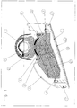
- the Actuators 23 and 24 are by the driver by means Controlled switches or the like, with the Actuators are connected via control lines (not ) Shown.
- the servomotors and the structure of Actuator including any gear are off known in the art and are therefore here only indicated schematically. However one recognizes in the schematic representation that the platform in here illustrated preferred embodiment for receiving the Engines 23, 24 is divided into two parts and by means of screws 5 is joined together.
- the base 21 of the actuator 2 is on a support 4th a vehicle (not shown) attached by a Counterpart 25 is braced against the base 21 and so the carrier 4 frictionally clamps.
- the tension can, as shown, for example, take place in that the Counterpart 25 positively connected to the base 21 with an opening between them, which in itself is smaller than the carrier 4.
- the one in this Opening inserted carrier 4 deforms the counterpart 25th elastic, so that it is braced against the base and at the same time pinching the carrier.
- the rearview mirror assembly can be in any Angular position with respect to the rotationally symmetrical carrier 4th be determined.
- a Glass support plate 1 by means of screws 5 directly attached.
- a mirror glass 11 by means Glued attached.
- Execution can be between mirror glass and glass carrier plate be arranged a mirror heater.
- a housing 3 fixed by means of screws 6. This is so formed in that it in the assembled state with projections 12 of the glass carrier plate over the entire circumference flush closes and thus prevents dirt or Moisture in the interior of the rearview mirror assembly arrive and the actuator 2, in particular the engines 23, 24 impair.
- the housing 3 also directly, i. without protrusions 12, on the mirror glass 11 issue.
- the projections 12 stabilize in addition the housing.
- a sealant such as a circumferential rubber seal
- the projections 12th be arranged facing circumference (not shown).
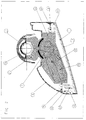
- Fig. 2 shows a rearview mirror assembly according to a second embodiment of the present invention. These differs from the first version only in that that both glass carrier plate 1 and 3 housing by means Clip fasteners are attached to the platform 22.
- the glass carrier plate 1 fastening clips 13, which in correspondingly shaped holes 26 of the Lock the platform under positive locking.
- mounting clips 13 and projections 12 of the glass carrier plate are so formed so that they engage the fastening clips 13 are slightly elastically deformed in the holes 26 and so glass carrier plate and platform together establish.
Landscapes
- Engineering & Computer Science (AREA)
- Multimedia (AREA)
- Mechanical Engineering (AREA)
- Physics & Mathematics (AREA)
- General Physics & Mathematics (AREA)
- Optics & Photonics (AREA)
- Rear-View Mirror Devices That Are Mounted On The Exterior Of The Vehicle (AREA)
Abstract
Description
Claims (7)
- Rückspiegelanordnung für Fahrzeuge, insbesondere für Nutzfahrzeuge, mit einer Glasträgerplatte (1), auf der ein Spiegelglas (11) angeordnet ist;
einer Stelleinheit (2) mit
einer Basis (21), die direkt an einem Träger (4) des Fahrzeugs befestigbar ist, und
einer Plattform (22), die gegenüber der Basis motorisch (23, 24) um wenigstens eine Achse drehbar ist; und
einem Gehäuse (3);
dadurch gekennzeichnet, daß
sowohl die Glasträgerplatte als auch das Gehäuse direkt an der Plattform befestigt sind. - Rückspiegelanordnung nach Anspruch 1, dadurch gekennzeichnet, daß die Plattform der Stelleinheit gegenüber der Basis um wenigstens zwei, insbesondere zueinander senkrechte, Achse drehbar ist.
- Rückspiegelanordnung nach einem der vorhergehenden Ansprüche, dadurch gekennzeichnet, daß die Basis der Stelleinheit am Träger des Fahrzeugs in beliebiger Position befestigbar ist.
- Rückspiegelanordnung nach einem der vorhergehenden Ansprüche, dadurch gekennzeichnet, daß die Basis der Stelleinheit mittels Form- und/oder Reibschluß am Träger des Fahrzeugs befestigbar ist.
- Rückspiegelanordnung nach einem der vorhergehenden Ansprüche, dadurch gekennzeichnet, daß die Stelleinheit weiters ein Gegenstück umfaßt, welches durch Verspannen gegen die Basis diese am Träger des Fahrzeugs befestigt.
- Rückspiegelanordnung nach einem der vorhergehenden Ansprüche, dadurch gekennzeichnet, daß die Glasträgerplatte und/oder das Gehäuse durch lösbare Befestigungsmittel, insbesondere durch Schrauben und/oder Klippverbindungen an der Plattform befestigt sind.
- Rückspiegelanordnung nach einem der vorhergehenden Ansprüche, dadurch gekennzeichnet, daß die Glasträgerplatte und/oder das Gehäuse durch unlösbare Befestigungsmittel, insbesondere durch Nieten und/oder Klebeverbindungen an der Plattform befestigt sind.
Applications Claiming Priority (2)
| Application Number | Priority Date | Filing Date | Title |
|---|---|---|---|
| DE10341818A DE10341818B4 (de) | 2003-09-10 | 2003-09-10 | Rückspiegelanordnung für Fahrzeuge |
| DE10341818 | 2003-09-10 |
Publications (2)
| Publication Number | Publication Date |
|---|---|
| EP1514732A1 true EP1514732A1 (de) | 2005-03-16 |
| EP1514732B1 EP1514732B1 (de) | 2006-07-19 |
Family
ID=34129739
Family Applications (1)
| Application Number | Title | Priority Date | Filing Date |
|---|---|---|---|
| EP04021623A Expired - Lifetime EP1514732B1 (de) | 2003-09-10 | 2004-09-10 | Rückspiegelanordnung für Fahrzeuge, insbesondere Nutzfahrzeuge |
Country Status (8)
| Country | Link |
|---|---|
| US (1) | US7044612B2 (de) |
| EP (1) | EP1514732B1 (de) |
| JP (1) | JP4482410B2 (de) |
| KR (1) | KR100962599B1 (de) |
| CN (1) | CN100371186C (de) |
| AT (1) | ATE333394T1 (de) |
| DE (2) | DE10341818B4 (de) |
| ES (1) | ES2270247T3 (de) |
Families Citing this family (18)
| Publication number | Priority date | Publication date | Assignee | Title |
|---|---|---|---|---|
| AU2003253938A1 (en) * | 2002-07-19 | 2004-02-09 | Magna Donnelly North America, L.L.C. | Rear view mirror with snap connection |
| CA2449142A1 (en) * | 2002-11-12 | 2004-05-12 | Magna Donnelly Mirrors North America L.L.C. | Mirror system with interlock attachment for reflective element |
| US8786704B2 (en) | 2007-08-09 | 2014-07-22 | Donnelly Corporation | Vehicle mirror assembly with wide angle element |
| DE102008053177A1 (de) | 2008-10-24 | 2010-05-06 | Mekra Lang Gmbh & Co. Kg | Rückspiegelanordnung für Fahrzeuge |
| US8047665B2 (en) * | 2009-06-15 | 2011-11-01 | Smr Patents S.A.R.L. | Rearview mirror assembly having a composite reflective surface |
| NL2004141C2 (nl) * | 2010-01-25 | 2011-07-26 | Mci Mirror Controls Int Nl Bv | Buitenspiegeleenheid. |
| US8336845B1 (en) | 2011-07-13 | 2012-12-25 | Lang-Mekra North America, Llc | Pivoting detent joint for a vehicle mirror assembly |
| JP5758252B2 (ja) * | 2011-09-20 | 2015-08-05 | 株式会社村上開明堂 | ドアミラー製造方法 |
| DE102011087572B3 (de) * | 2011-12-01 | 2013-03-07 | Mekra Lang Gmbh & Co. Kg | Spiegelkomponente für eine Kraftfahrzeug-Spiegelanordnung, Spiegelanordnung mit einer solchen Spiegelkomponente sowie Tragstruktur Verstelleinheit für eine solche Spiegelkomponente oder eine solche Spiegelanordnung |
| DE102012108480B3 (de) * | 2012-09-11 | 2014-02-20 | SMR Patents S.à.r.l. | Kopfteil |
| US10744947B2 (en) * | 2012-01-24 | 2020-08-18 | SMR Patents S.à.r.l. | Head section for a rear view device |
| DE102012221348B4 (de) | 2012-11-22 | 2014-06-05 | Mekra Lang Gmbh & Co. Kg | Spiegelkopf, insbesondere für einen Fahrzeugaußenspiegel |
| CN105579288B (zh) * | 2013-08-30 | 2017-11-10 | 梅克拉-朗两合公司 | 具有集成的管锚定件的窝形接头 |
| NL2013771B1 (nl) * | 2014-11-11 | 2016-10-06 | MCI (Mirror Controls International) Netherlands B V | Inrichting voor het verstellen van een schaalvormig behuizingsdeel, een draagframe voor gebruik in een dergelijke inrichting, en een voertuig voorzien van een dergelijke inrichting. |
| CN107139838B (zh) * | 2017-05-31 | 2019-06-28 | 安徽江淮汽车集团股份有限公司 | 一种汽车智能内后视镜支架总成 |
| US11242006B2 (en) | 2019-07-22 | 2022-02-08 | Honda Motor Co., Ltd. | Vehicle door mirror assembly |
| US11465562B2 (en) * | 2019-10-31 | 2022-10-11 | Nissan North America, Inc. | Vehicle side mirror assembly |
| JP2023055459A (ja) * | 2021-10-06 | 2023-04-18 | カワサキモータース株式会社 | ミラー装置及び鞍乗り型乗物 |
Citations (2)
| Publication number | Priority date | Publication date | Assignee | Title |
|---|---|---|---|---|
| EP0090909A2 (de) * | 1982-04-07 | 1983-10-12 | MEKRA Rangau Plastics GmbH & Co KG | Motorisch verstellbarer Rückspiegel |
| US6340231B1 (en) * | 1998-04-01 | 2002-01-22 | Donnelly Hohe Gmbh & Co. Kg | Electrically adjustable external rear view mirror |
Family Cites Families (8)
| Publication number | Priority date | Publication date | Assignee | Title |
|---|---|---|---|---|
| DE3811448A1 (de) * | 1987-09-09 | 1989-03-23 | Mekra Rangau Plastics | Motorisch verstellbarer rueckspiegel |
| DE58903861D1 (de) * | 1988-05-20 | 1993-04-29 | Mekra Rangau Plastics | Motorisch verstellbarer rueckspiegel. |
| EP0372485A3 (de) * | 1988-12-06 | 1991-11-21 | Ichikoh Industries Limited | Fahrzeugaussenspiegel |
| DE8914759U1 (de) * | 1989-12-15 | 1991-04-11 | Hohe Kg, 6981 Collenberg | Außenspiegel für ein Kraftfahrzeug mit aufsteckbarer Kappe |
| US5621577A (en) * | 1990-03-29 | 1997-04-15 | Mekra Rangau Plastics Gmbh & Co. Kg | External rear-view mirror for commerical vehicles |
| DE4339279A1 (de) * | 1993-11-18 | 1995-05-24 | Mekra Rangau Plastics | Rückblickspiegel für Kraftfahrzeuge |
| DE4343691A1 (de) * | 1993-12-21 | 1995-06-22 | Mekra Rangau Plastics | Rückblickspiegel, insbesondere für Lkw |
| US5687035A (en) * | 1996-03-22 | 1997-11-11 | Heinrich Lang | Rear-view mirror assembly having dual motor driven mirrors |
-
2003
- 2003-09-10 DE DE10341818A patent/DE10341818B4/de not_active Expired - Fee Related
-
2004
- 2004-09-08 US US10/936,060 patent/US7044612B2/en not_active Expired - Fee Related
- 2004-09-09 CN CNB2004100784782A patent/CN100371186C/zh not_active Expired - Fee Related
- 2004-09-10 KR KR1020040072621A patent/KR100962599B1/ko not_active Expired - Fee Related
- 2004-09-10 ES ES04021623T patent/ES2270247T3/es not_active Expired - Lifetime
- 2004-09-10 JP JP2004263346A patent/JP4482410B2/ja not_active Expired - Fee Related
- 2004-09-10 AT AT04021623T patent/ATE333394T1/de not_active IP Right Cessation
- 2004-09-10 DE DE502004000979T patent/DE502004000979D1/de not_active Expired - Lifetime
- 2004-09-10 EP EP04021623A patent/EP1514732B1/de not_active Expired - Lifetime
Patent Citations (2)
| Publication number | Priority date | Publication date | Assignee | Title |
|---|---|---|---|---|
| EP0090909A2 (de) * | 1982-04-07 | 1983-10-12 | MEKRA Rangau Plastics GmbH & Co KG | Motorisch verstellbarer Rückspiegel |
| US6340231B1 (en) * | 1998-04-01 | 2002-01-22 | Donnelly Hohe Gmbh & Co. Kg | Electrically adjustable external rear view mirror |
Also Published As
| Publication number | Publication date |
|---|---|
| EP1514732B1 (de) | 2006-07-19 |
| ES2270247T3 (es) | 2007-04-01 |
| JP2005082150A (ja) | 2005-03-31 |
| ATE333394T1 (de) | 2006-08-15 |
| JP4482410B2 (ja) | 2010-06-16 |
| DE502004000979D1 (de) | 2006-08-31 |
| US7044612B2 (en) | 2006-05-16 |
| CN100371186C (zh) | 2008-02-27 |
| DE10341818B4 (de) | 2005-10-20 |
| US20050052764A1 (en) | 2005-03-10 |
| DE10341818A1 (de) | 2005-04-28 |
| KR20050026899A (ko) | 2005-03-16 |
| KR100962599B1 (ko) | 2010-06-11 |
| CN1597392A (zh) | 2005-03-23 |
Similar Documents
| Publication | Publication Date | Title |
|---|---|---|
| EP1514732B1 (de) | Rückspiegelanordnung für Fahrzeuge, insbesondere Nutzfahrzeuge | |
| EP2673169B1 (de) | Kameraanordnung für ein fahrzeug und verfahren zum einbau | |
| DE60203143T2 (de) | Fahrzeugscharnier mit einem abnehmbaren Bauteil geeignet für strukturellen Wiederzusammenbau | |
| EP1444114B1 (de) | Halterung für ein justierbares gehäuse | |
| EP3844046B1 (de) | Elektrisch verstellbare steer-by-wire lenksäule und kraftfahrzeug | |
| DE102018110525A1 (de) | Verfahren zur Montage einer Getriebekomponente einer Sitzhöhenverstellung | |
| WO2024115591A1 (de) | Türgriffeinheit für eine fahrzeugtür | |
| DE102011078230A1 (de) | Verschwenken eines Objekts, insbesondere einer Fahrzeugkamera | |
| DE10232105B4 (de) | Vorrichtung zum automatischen Verschwenken einer Kraftfahrzeugtür | |
| WO2011006846A1 (de) | Mitnehmer zur anbindung einer fensterscheibe an einen fensterheber eines kraftfahrzeugs | |
| DE102004008070B4 (de) | Arm für eine pantographische Scharniervorrichtung | |
| EP0964975B1 (de) | Antriebsvorrichtung für ein seitenausstellfenster | |
| DE102013223848B4 (de) | Rückspiegelanordnung an einem Fahrzeug, Fahrzeug sowie Verfahren zur Montage eines Außenrückspiegels an einer Fahrzeugtür | |
| DE19533655A1 (de) | Vorrichtung zur Befestigung von Bauteilen an Trägerteilen eines Kraftfahrzeuges | |
| DE102016005581B4 (de) | Verbindungselement zur Verbindung eines Kraftfahrzeugfrontends mit einem Kraftfahrzeug | |
| DE102006032977A1 (de) | Sonnenschutzvorrichtung mit elektrischem Sonnenschott | |
| DE102016114084B4 (de) | Montagevorrichtung für den Schließbügel der Heckklappe eines Kraftfahrzeuges, insbesondere eines Personenkraftwagens | |
| DE102013200003A1 (de) | Wischanlage für ein Fahrzeug | |
| DE102024118856B4 (de) | Baugruppe einer Fahrzeugtür mit einem Türmodul und einer Türantriebsvorrichtung | |
| DE10037443B4 (de) | Vorrichtung zum Verbinden eines auf einem Halteelement montierten Türschlosses mit einem Türmodulträger einer Kraftfahrzeugtür | |
| DE19654446A1 (de) | Kraftfahrzeug mit einer Karosserietragstruktur und Montagelehre | |
| DE19911798A1 (de) | Libellenbefestigung | |
| DE19517645B4 (de) | Schiebedach sowie Verfahren und Vorrichtung zur Montage eines Schiebedachs | |
| EP1651835A1 (de) | Getriebe-antriebseinheit | |
| DE102004011650A1 (de) | Kraftfahrzeugtürschloßeinrichtung |
Legal Events
| Date | Code | Title | Description |
|---|---|---|---|
| PUAI | Public reference made under article 153(3) epc to a published international application that has entered the european phase |
Free format text: ORIGINAL CODE: 0009012 |
|
| AK | Designated contracting states |
Kind code of ref document: A1 Designated state(s): AT BE BG CH CY CZ DE DK EE ES FI FR GB GR HU IE IT LI LU MC NL PL PT RO SE SI SK TR |
|
| AX | Request for extension of the european patent |
Extension state: AL HR LT LV MK |
|
| 17P | Request for examination filed |
Effective date: 20050429 |
|
| AKX | Designation fees paid |
Designated state(s): AT BE BG CH CY CZ DE DK EE ES FI FR GB GR HU IE IT LI LU MC NL PL PT RO SE SI SK TR |
|
| GRAP | Despatch of communication of intention to grant a patent |
Free format text: ORIGINAL CODE: EPIDOSNIGR1 |
|
| GRAS | Grant fee paid |
Free format text: ORIGINAL CODE: EPIDOSNIGR3 |
|
| GRAA | (expected) grant |
Free format text: ORIGINAL CODE: 0009210 |
|
| AK | Designated contracting states |
Kind code of ref document: B1 Designated state(s): AT BE BG CH CY CZ DE DK EE ES FI FR GB GR HU IE IT LI LU MC NL PL PT RO SE SI SK TR |
|
| PG25 | Lapsed in a contracting state [announced via postgrant information from national office to epo] |
Ref country code: IE Free format text: LAPSE BECAUSE OF FAILURE TO SUBMIT A TRANSLATION OF THE DESCRIPTION OR TO PAY THE FEE WITHIN THE PRESCRIBED TIME-LIMIT Effective date: 20060719 Ref country code: SK Free format text: LAPSE BECAUSE OF FAILURE TO SUBMIT A TRANSLATION OF THE DESCRIPTION OR TO PAY THE FEE WITHIN THE PRESCRIBED TIME-LIMIT Effective date: 20060719 Ref country code: FI Free format text: LAPSE BECAUSE OF FAILURE TO SUBMIT A TRANSLATION OF THE DESCRIPTION OR TO PAY THE FEE WITHIN THE PRESCRIBED TIME-LIMIT Effective date: 20060719 Ref country code: SI Free format text: LAPSE BECAUSE OF FAILURE TO SUBMIT A TRANSLATION OF THE DESCRIPTION OR TO PAY THE FEE WITHIN THE PRESCRIBED TIME-LIMIT Effective date: 20060719 Ref country code: RO Free format text: LAPSE BECAUSE OF FAILURE TO SUBMIT A TRANSLATION OF THE DESCRIPTION OR TO PAY THE FEE WITHIN THE PRESCRIBED TIME-LIMIT Effective date: 20060719 Ref country code: NL Free format text: LAPSE BECAUSE OF FAILURE TO SUBMIT A TRANSLATION OF THE DESCRIPTION OR TO PAY THE FEE WITHIN THE PRESCRIBED TIME-LIMIT Effective date: 20060719 Ref country code: CZ Free format text: LAPSE BECAUSE OF FAILURE TO SUBMIT A TRANSLATION OF THE DESCRIPTION OR TO PAY THE FEE WITHIN THE PRESCRIBED TIME-LIMIT Effective date: 20060719 Ref country code: PL Free format text: LAPSE BECAUSE OF FAILURE TO SUBMIT A TRANSLATION OF THE DESCRIPTION OR TO PAY THE FEE WITHIN THE PRESCRIBED TIME-LIMIT Effective date: 20060719 |
|
| REG | Reference to a national code |
Ref country code: GB Ref legal event code: FG4D Free format text: NOT ENGLISH |
|
| REG | Reference to a national code |
Ref country code: CH Ref legal event code: EP |
|
| REG | Reference to a national code |
Ref country code: IE Ref legal event code: FG4D Free format text: LANGUAGE OF EP DOCUMENT: GERMAN |
|
| REF | Corresponds to: |
Ref document number: 502004000979 Country of ref document: DE Date of ref document: 20060831 Kind code of ref document: P |
|
| GBT | Gb: translation of ep patent filed (gb section 77(6)(a)/1977) |
Effective date: 20060830 |
|
| PG25 | Lapsed in a contracting state [announced via postgrant information from national office to epo] |
Ref country code: MC Free format text: LAPSE BECAUSE OF NON-PAYMENT OF DUE FEES Effective date: 20060930 Ref country code: BE Free format text: LAPSE BECAUSE OF NON-PAYMENT OF DUE FEES Effective date: 20060930 |
|
| REG | Reference to a national code |
Ref country code: SE Ref legal event code: TRGR |
|
| PG25 | Lapsed in a contracting state [announced via postgrant information from national office to epo] |
Ref country code: BG Free format text: LAPSE BECAUSE OF FAILURE TO SUBMIT A TRANSLATION OF THE DESCRIPTION OR TO PAY THE FEE WITHIN THE PRESCRIBED TIME-LIMIT Effective date: 20061019 Ref country code: DK Free format text: LAPSE BECAUSE OF FAILURE TO SUBMIT A TRANSLATION OF THE DESCRIPTION OR TO PAY THE FEE WITHIN THE PRESCRIBED TIME-LIMIT Effective date: 20061019 |
|
| PG25 | Lapsed in a contracting state [announced via postgrant information from national office to epo] |
Ref country code: PT Free format text: LAPSE BECAUSE OF FAILURE TO SUBMIT A TRANSLATION OF THE DESCRIPTION OR TO PAY THE FEE WITHIN THE PRESCRIBED TIME-LIMIT Effective date: 20061219 |
|
| NLV1 | Nl: lapsed or annulled due to failure to fulfill the requirements of art. 29p and 29m of the patents act | ||
| ET | Fr: translation filed | ||
| REG | Reference to a national code |
Ref country code: IE Ref legal event code: FD4D |
|
| REG | Reference to a national code |
Ref country code: ES Ref legal event code: FG2A Ref document number: 2270247 Country of ref document: ES Kind code of ref document: T3 |
|
| PLBE | No opposition filed within time limit |
Free format text: ORIGINAL CODE: 0009261 |
|
| STAA | Information on the status of an ep patent application or granted ep patent |
Free format text: STATUS: NO OPPOSITION FILED WITHIN TIME LIMIT |
|
| 26N | No opposition filed |
Effective date: 20070420 |
|
| PG25 | Lapsed in a contracting state [announced via postgrant information from national office to epo] |
Ref country code: AT Free format text: LAPSE BECAUSE OF NON-PAYMENT OF DUE FEES Effective date: 20060910 |
|
| BERE | Be: lapsed |
Owner name: MEKRA LANG G.M.B.H. & CO. KG Effective date: 20060930 |
|
| PG25 | Lapsed in a contracting state [announced via postgrant information from national office to epo] |
Ref country code: GR Free format text: LAPSE BECAUSE OF FAILURE TO SUBMIT A TRANSLATION OF THE DESCRIPTION OR TO PAY THE FEE WITHIN THE PRESCRIBED TIME-LIMIT Effective date: 20061020 |
|
| PG25 | Lapsed in a contracting state [announced via postgrant information from national office to epo] |
Ref country code: EE Free format text: LAPSE BECAUSE OF FAILURE TO SUBMIT A TRANSLATION OF THE DESCRIPTION OR TO PAY THE FEE WITHIN THE PRESCRIBED TIME-LIMIT Effective date: 20060719 |
|
| PG25 | Lapsed in a contracting state [announced via postgrant information from national office to epo] |
Ref country code: LU Free format text: LAPSE BECAUSE OF NON-PAYMENT OF DUE FEES Effective date: 20060910 Ref country code: HU Free format text: LAPSE BECAUSE OF FAILURE TO SUBMIT A TRANSLATION OF THE DESCRIPTION OR TO PAY THE FEE WITHIN THE PRESCRIBED TIME-LIMIT Effective date: 20070120 |
|
| PG25 | Lapsed in a contracting state [announced via postgrant information from national office to epo] |
Ref country code: CY Free format text: LAPSE BECAUSE OF FAILURE TO SUBMIT A TRANSLATION OF THE DESCRIPTION OR TO PAY THE FEE WITHIN THE PRESCRIBED TIME-LIMIT Effective date: 20060719 |
|
| REG | Reference to a national code |
Ref country code: CH Ref legal event code: PL |
|
| PG25 | Lapsed in a contracting state [announced via postgrant information from national office to epo] |
Ref country code: CH Free format text: LAPSE BECAUSE OF NON-PAYMENT OF DUE FEES Effective date: 20060930 Ref country code: LI Free format text: LAPSE BECAUSE OF NON-PAYMENT OF DUE FEES Effective date: 20060930 |
|
| PG25 | Lapsed in a contracting state [announced via postgrant information from national office to epo] |
Ref country code: CH Free format text: LAPSE BECAUSE OF NON-PAYMENT OF DUE FEES Effective date: 20080930 Ref country code: LI Free format text: LAPSE BECAUSE OF NON-PAYMENT OF DUE FEES Effective date: 20080930 |
|
| PGFP | Annual fee paid to national office [announced via postgrant information from national office to epo] |
Ref country code: SE Payment date: 20140923 Year of fee payment: 11 |
|
| PGFP | Annual fee paid to national office [announced via postgrant information from national office to epo] |
Ref country code: IT Payment date: 20140929 Year of fee payment: 11 |
|
| PG25 | Lapsed in a contracting state [announced via postgrant information from national office to epo] |
Ref country code: IT Free format text: LAPSE BECAUSE OF NON-PAYMENT OF DUE FEES Effective date: 20150910 |
|
| REG | Reference to a national code |
Ref country code: SE Ref legal event code: EUG |
|
| PG25 | Lapsed in a contracting state [announced via postgrant information from national office to epo] |
Ref country code: SE Free format text: LAPSE BECAUSE OF NON-PAYMENT OF DUE FEES Effective date: 20150911 |
|
| REG | Reference to a national code |
Ref country code: FR Ref legal event code: PLFP Year of fee payment: 13 |
|
| PGFP | Annual fee paid to national office [announced via postgrant information from national office to epo] |
Ref country code: GB Payment date: 20160921 Year of fee payment: 13 |
|
| PGFP | Annual fee paid to national office [announced via postgrant information from national office to epo] |
Ref country code: FR Payment date: 20160922 Year of fee payment: 13 |
|
| PGFP | Annual fee paid to national office [announced via postgrant information from national office to epo] |
Ref country code: ES Payment date: 20160923 Year of fee payment: 13 Ref country code: TR Payment date: 20160902 Year of fee payment: 13 |
|
| GBPC | Gb: european patent ceased through non-payment of renewal fee |
Effective date: 20170910 |
|
| REG | Reference to a national code |
Ref country code: FR Ref legal event code: ST Effective date: 20180531 |
|
| PG25 | Lapsed in a contracting state [announced via postgrant information from national office to epo] |
Ref country code: GB Free format text: LAPSE BECAUSE OF NON-PAYMENT OF DUE FEES Effective date: 20170910 |
|
| PG25 | Lapsed in a contracting state [announced via postgrant information from national office to epo] |
Ref country code: FR Free format text: LAPSE BECAUSE OF NON-PAYMENT OF DUE FEES Effective date: 20171002 |
|
| REG | Reference to a national code |
Ref country code: ES Ref legal event code: FD2A Effective date: 20181024 |
|
| PG25 | Lapsed in a contracting state [announced via postgrant information from national office to epo] |
Ref country code: ES Free format text: LAPSE BECAUSE OF NON-PAYMENT OF DUE FEES Effective date: 20170911 |
|
| PGFP | Annual fee paid to national office [announced via postgrant information from national office to epo] |
Ref country code: DE Payment date: 20190823 Year of fee payment: 16 |
|
| REG | Reference to a national code |
Ref country code: DE Ref legal event code: R119 Ref document number: 502004000979 Country of ref document: DE |
|
| PG25 | Lapsed in a contracting state [announced via postgrant information from national office to epo] |
Ref country code: DE Free format text: LAPSE BECAUSE OF NON-PAYMENT OF DUE FEES Effective date: 20210401 |
|
| PG25 | Lapsed in a contracting state [announced via postgrant information from national office to epo] |
Ref country code: TR Free format text: LAPSE BECAUSE OF NON-PAYMENT OF DUE FEES Effective date: 20170910 |