EP1514728A2 - Véhicule-silo, notament véhicule de charge - Google Patents
Véhicule-silo, notament véhicule de charge Download PDFInfo
- Publication number
- EP1514728A2 EP1514728A2 EP04021258A EP04021258A EP1514728A2 EP 1514728 A2 EP1514728 A2 EP 1514728A2 EP 04021258 A EP04021258 A EP 04021258A EP 04021258 A EP04021258 A EP 04021258A EP 1514728 A2 EP1514728 A2 EP 1514728A2
- Authority
- EP
- European Patent Office
- Prior art keywords
- conveyor
- silo
- vehicle
- vehicle according
- driver
- Prior art date
- Legal status (The legal status is an assumption and is not a legal conclusion. Google has not performed a legal analysis and makes no representation as to the accuracy of the status listed.)
- Withdrawn
Links
Images


Classifications
-
- B—PERFORMING OPERATIONS; TRANSPORTING
- B28—WORKING CEMENT, CLAY, OR STONE
- B28C—PREPARING CLAY; PRODUCING MIXTURES CONTAINING CLAY OR CEMENTITIOUS MATERIAL, e.g. PLASTER
- B28C5/00—Apparatus or methods for producing mixtures of cement with other substances, e.g. slurries, mortars, porous or fibrous compositions
- B28C5/42—Apparatus specially adapted for being mounted on vehicles with provision for mixing during transport
- B28C5/4203—Details; Accessories
- B28C5/4234—Charge or discharge systems therefor
- B28C5/4244—Discharging; Concrete conveyor means, chutes or spouts therefor
- B28C5/4248—Discharging; Concrete conveyor means, chutes or spouts therefor using chutes
- B28C5/4251—Discharging; Concrete conveyor means, chutes or spouts therefor using chutes telescopic or foldable chutes
-
- B—PERFORMING OPERATIONS; TRANSPORTING
- B28—WORKING CEMENT, CLAY, OR STONE
- B28C—PREPARING CLAY; PRODUCING MIXTURES CONTAINING CLAY OR CEMENTITIOUS MATERIAL, e.g. PLASTER
- B28C5/00—Apparatus or methods for producing mixtures of cement with other substances, e.g. slurries, mortars, porous or fibrous compositions
- B28C5/42—Apparatus specially adapted for being mounted on vehicles with provision for mixing during transport
- B28C5/4203—Details; Accessories
- B28C5/4234—Charge or discharge systems therefor
- B28C5/4244—Discharging; Concrete conveyor means, chutes or spouts therefor
- B28C5/4258—Discharging; Concrete conveyor means, chutes or spouts therefor using pumps or transporting screws
-
- B—PERFORMING OPERATIONS; TRANSPORTING
- B60—VEHICLES IN GENERAL
- B60P—VEHICLES ADAPTED FOR LOAD TRANSPORTATION OR TO TRANSPORT, TO CARRY, OR TO COMPRISE SPECIAL LOADS OR OBJECTS
- B60P1/00—Vehicles predominantly for transporting loads and modified to facilitate loading, consolidating the load, or unloading
- B60P1/36—Vehicles predominantly for transporting loads and modified to facilitate loading, consolidating the load, or unloading using endless chains or belts thereon
-
- B—PERFORMING OPERATIONS; TRANSPORTING
- B60—VEHICLES IN GENERAL
- B60P—VEHICLES ADAPTED FOR LOAD TRANSPORTATION OR TO TRANSPORT, TO CARRY, OR TO COMPRISE SPECIAL LOADS OR OBJECTS
- B60P3/00—Vehicles adapted to transport, to carry or to comprise special loads or objects
- B60P3/16—Vehicles adapted to transport, to carry or to comprise special loads or objects for carrying mixed concrete, e.g. having rotatable drums
-
- B—PERFORMING OPERATIONS; TRANSPORTING
- B60—VEHICLES IN GENERAL
- B60P—VEHICLES ADAPTED FOR LOAD TRANSPORTATION OR TO TRANSPORT, TO CARRY, OR TO COMPRISE SPECIAL LOADS OR OBJECTS
- B60P3/00—Vehicles adapted to transport, to carry or to comprise special loads or objects
- B60P3/22—Tank vehicles
- B60P3/2205—Constructional features
-
- B—PERFORMING OPERATIONS; TRANSPORTING
- B60—VEHICLES IN GENERAL
- B60P—VEHICLES ADAPTED FOR LOAD TRANSPORTATION OR TO TRANSPORT, TO CARRY, OR TO COMPRISE SPECIAL LOADS OR OBJECTS
- B60P3/00—Vehicles adapted to transport, to carry or to comprise special loads or objects
- B60P3/22—Tank vehicles
- B60P3/224—Tank vehicles comprising auxiliary devices, e.g. for unloading or level indicating
- B60P3/2245—Adaptations for loading or unloading
Definitions
- the invention relates to a silo vehicle, in particular a Charging vehicle, for electrolysis cells for the production of Aluminum having the features of the preamble of claim 1.
- Such loading vehicles as the anode roofing vehicles or the alumina / cryolite feed vehicles of Aluminum industry are special vehicles that have the task to charge the Elekrolysezellen or electrolysis ovens, wherein the raw material, namely the alumina-cryolite mixture on the Bath surface is distributed and the anodes are covered.
- These Vehicles may have a trapezoidal silo container, which is fixedly attached to the vehicle and the over Screw or chain conveyor systems or pneumatically emptied becomes. The emptying of the silo container of the vehicles takes place in usually at ground level and up to a height of about 1 m above Hall.
- trapezoidal silo containers Charging vehicles known which the buffers of Charge electrolysis cells with central, automatic Distribution systems are provided.
- the refill points of this Distribution systems are generally at a height of 1.5 m to 3 m above the corridor.
- the emptying of the silo container is due to the height to be overcome only via Kettenoder Screw transport systems or pneumatically possible. there the bulk material must be separated from the lower area of the Silo containers are conveyed to the required height.
- the invention is based on the object, the generic Silo, in particular to improve the loading vehicle in such a way that sticking and caking of the bulk material in the silo container and be avoided in the promotion system and that with a single Vehicle both openings at floor level and cache can be loaded at higher altitudes.
- the object is in a generic silo vehicle, in particular a charging vehicle, according to the invention by the characterizing features of claim 1 solved.
- Advantageous embodiments of the invention are the subject of Dependent claims.
- the provided with a driven continuous conveyor Silo vehicle can also be higher taking advantage of the vehicle height Serve located filling openings, both by the internal screw in the silo container as well as due to the Forced promotion of continuous conveyor bonding and Caking of the bulk material in the silo container and in the continuous conveyor be avoided.
- Lower and lying on ground level Einhellö Anlagenen can also by the continuous conveyor, optionally in conjunction with a downward Slide, to be operated.
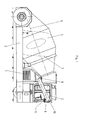
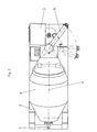
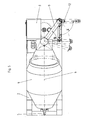
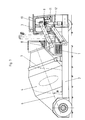
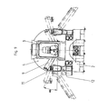
- the illustrated silo or loading vehicle serves in the Aluminum industry for charging electrolysis cells with a pourable mixture of alumina and cryolite. That through a motor 1 driven loading vehicle consists of a chassis 2, on the front side (Fig. 1 - 6) or centered (Fig. 7 - 9) a driver's pulpit 3 is arranged. Behind the driver's cockpit 3 is a silo container 4 on the chassis 2 arranged in two opposite directions Rotation directions is rotatable. The rotation of the silo container 4 takes place via a hydraulic motor 5.
- the silo container 4 is inclined in the direction of travel inclined, wherein the longitudinal axis 6 of the silo 4 with the Horizontal angle ⁇ of 20 °.
- an internal screw 7 fixed so that in one direction of rotation, the inside Snail 7 located in the silo box 4 bulk material in Direction towards the discharge end of the silo container 4 promotes. This discharge end is located at the top of the Silo container 4 just behind the driver's pulpit 3.
- the bulk material is constantly in Movement held by the silo container 4 in the direction of rotation is rotated, which is directed opposite to the direction of rotation, in which promotes the internal screw 7. This way will prevents the bulk material from vibration or impact is compressed during the journey.
- the discharge end of the silo container 4 is as swivel Head part 8 is formed, which in the horizontal by an angle ⁇ from 0 ° to 240 ° is pivotable.
- the screw conveyor system 9 consists of at least one screw disposed within a housing 10, which has a driven worm shaft with an attached Has helical thread.
- At the front end is the case of the Screw conveyor system 9 with a downward facing Abschstutzen 11 provided.
- In the starting position solid Lines in Fig. 2
- the screw conveyor system In the starting position (solid Lines in Fig. 2) is the screw conveyor system. 9 pointing obliquely in the direction of travel above the base of the Chassis 2.
- the screw conveyor system 9 can be used together with the pivotable head part 8 of the silo 4 from this Starting position pivoted by an angle ⁇ from 0 ° to 240 ° and brought to the electrolysis cell via a filling opening become.
- the bulk material contained in the silo container 4 becomes transported by the internal screw 7 to the head part 8 and via the screw conveyor 9 safely to a high promoted filling opening of the electrolysis cell.
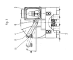
- Of the Loading process can be monitored from the driver's cockpit 3 from become.
- the screw conveyor 9 can also be located lower Filling openings, z. B. load such at floor level or the Distribute material on the bath surface of the electrolysis cell.
- this is an open chute 12 to help taken on the side next to the driver's seat 3 on the Chassis 2 is mounted and directed downwards.
- there the entrance end of the chute 12 is below the Abschstutzens 11 of the screw conveyor system 9, if this is in the starting position.
- an open chute 12 can also be used a delivery pipe.
- the chute 12 is around an angle ⁇ pivoting, whereby the exit end of the chute 12 from the area of the chassis 2 on the bath surface of the Electrolysis cell swung out and thus the material can be evenly distributed.
- two chutes 12 or delivery pipes be present on both sides of the Driver's pulley 3 are mounted on the chassis 2.
- the driver's cab 3 in the middle of the chassis 2 arranged.
- the two slides 12 are available with a Screw conveyor system 9, around the driver's cab 3 around is pivoted, or with two screw conveyor 9 in Connection.
- screw conveyor system can also other continuous conveyors, such as a chain conveyor, a belt conveyor or a pneumatic conveyor can be used.
Landscapes
- Engineering & Computer Science (AREA)
- Mechanical Engineering (AREA)
- Transportation (AREA)
- Health & Medical Sciences (AREA)
- Public Health (AREA)
- Structural Engineering (AREA)
- Filling Or Emptying Of Bunkers, Hoppers, And Tanks (AREA)
Applications Claiming Priority (2)
| Application Number | Priority Date | Filing Date | Title |
|---|---|---|---|
| DE10342235 | 2003-09-11 | ||
| DE2003142235 DE10342235A1 (de) | 2003-09-11 | 2003-09-11 | Silofahrzeug, insbesondere Beschickungsfahrzeug |
Publications (2)
| Publication Number | Publication Date |
|---|---|
| EP1514728A2 true EP1514728A2 (fr) | 2005-03-16 |
| EP1514728A3 EP1514728A3 (fr) | 2006-03-15 |
Family
ID=34129788
Family Applications (1)
| Application Number | Title | Priority Date | Filing Date |
|---|---|---|---|
| EP04021258A Withdrawn EP1514728A3 (fr) | 2003-09-11 | 2004-09-08 | Véhicule-silo, notament véhicule de charge |
Country Status (5)
| Country | Link |
|---|---|
| EP (1) | EP1514728A3 (fr) |
| CA (1) | CA2481132A1 (fr) |
| DE (1) | DE10342235A1 (fr) |
| NO (1) | NO20043806L (fr) |
| ZA (1) | ZA200407120B (fr) |
Family Cites Families (8)
| Publication number | Priority date | Publication date | Assignee | Title |
|---|---|---|---|---|
| US2859949A (en) * | 1955-07-18 | 1958-11-11 | Willard J Jack | Forward discharging transit concrete mixer |
| US2883076A (en) * | 1958-04-14 | 1959-04-21 | Harold S Palmer | Material handling system |
| US3633879A (en) * | 1969-05-01 | 1972-01-11 | Challenge Cook Bros Inc | Concrete transit mixer with forward discharge mechanism |
| DE2701699A1 (de) * | 1977-01-17 | 1978-07-20 | Louis Amour | Vorrichtung zum falten eines foerdergurtes fuer ein mit einer betonmischtrommel versehenes fahrzeug |
| IT1098239B (it) * | 1978-08-09 | 1985-09-07 | Cie Italiana Forne Acciaio Spa | Autobetoniera atta a conseniera atta a consentire al guidatore il controllo visivo diretto delle operazioni di carico e scarico del calcestruzzo |
| DE3331314A1 (de) * | 1983-08-31 | 1985-10-03 | Hellmut 2104 Hamburg Hupfeld | Transportmischer fuer mischbare baustoffe |
| DE19845573A1 (de) * | 1998-10-02 | 2000-04-06 | Vaw Ver Aluminium Werke Ag | Silofahrzeug |
| DE20021668U1 (de) * | 2000-12-21 | 2001-03-08 | Liebherr-Mischtechnik Gmbh, 88427 Bad Schussenried | Fahrzeug, vorzugsweise Fahrmischer, mit einem an den Fahrzeugrahmen angebauten schwenkbaren Förderband |
-
2003
- 2003-09-11 DE DE2003142235 patent/DE10342235A1/de not_active Ceased
-
2004
- 2004-09-07 ZA ZA200407120A patent/ZA200407120B/xx unknown
- 2004-09-08 EP EP04021258A patent/EP1514728A3/fr not_active Withdrawn
- 2004-09-10 NO NO20043806A patent/NO20043806L/no unknown
- 2004-09-10 CA CA 2481132 patent/CA2481132A1/fr not_active Abandoned
Also Published As
| Publication number | Publication date |
|---|---|
| CA2481132A1 (fr) | 2005-03-11 |
| DE10342235A1 (de) | 2005-04-07 |
| ZA200407120B (en) | 2004-11-08 |
| NO20043806L (no) | 2005-03-14 |
| EP1514728A3 (fr) | 2006-03-15 |
Similar Documents
| Publication | Publication Date | Title |
|---|---|---|
| DE69108638T2 (de) | Vorrichtung und Verfahren zum Entladen von Schüttgut. | |
| DE3390301C2 (de) | Verfahren und Vorrichtung für den Transport pulvrigen oder teilchenförmigen Materials | |
| DE3422569C2 (fr) | ||
| DE7730505U1 (de) | Mobile entladevorrichtung fuer massengut | |
| DE3390175C2 (fr) | ||
| DE8704215U1 (de) | Vorrichtung zum Transport und zur baustellenseitigen Bevorratung von schüttgutartigen Baustoffen | |
| DE1940714A1 (de) | Vorrichtung zum Austragen von Schuettguetern aus Silos | |
| EP0658409B1 (fr) | Machine de mélange | |
| DE19960118C2 (de) | Mischeinrichtung für mobile Mahl- und Mischanlagen | |
| EP1514728A2 (fr) | Véhicule-silo, notament véhicule de charge | |
| DE3426806C2 (de) | Silo mit kreisrundem Grundriß für Schüttgüter und einem an einer Stützsäule heb- und senkbar angeordneten Querförderer | |
| DE2057064B2 (de) | Einrichtung zum Versorgen von z.B. in verschiedenen Stockwerken von einem Gebäude od. dgl. aufgestellten Verputzmaschinen | |
| DE7908438U1 (de) | Iso-container fuer pulverfoermiges melamin | |
| DE19724504A1 (de) | Zweizylinderdickstoffpumpe | |
| DE3429023C2 (fr) | ||
| DE4413699C2 (de) | Behälter für Schüttgüter und zähflüssige Güter | |
| EP0429693B1 (fr) | Réservoir | |
| DE3604474C2 (fr) | ||
| DE568864C (de) | Foerdereinrichtung fuer Massengueter, bestehend aus einem drehbar gelagerten Foerderrohr, in dessen Innenraum sich eine mit dem Rohr fest verbundene Foerderschnecke befindet | |
| DE1914382A1 (de) | Muellwagen | |
| AT15104U2 (de) | Mobile Vorrichtung zum Zerkleinern von stückigem Gut | |
| DE9405653U1 (de) | Vorrichtung zum Verbinden einer stationären Schüttgutquelle mit einer längs einer vorbestimmten Ladestrecke verfahrbaren Ladeeinrichtung | |
| AT243149B (de) | Vorrichtung zum Beschicken von Automischern od. dgl. mit Baustoffen | |
| AT383334B (de) | Vorrichtung fuer die zu- und abfuhr und die gleichmaessige verteilung von schuettgut, insbesondere flugasche, in einem tank | |
| EP0427931A1 (fr) | Dispositif de déchargement pour silos contenant des produits en vrac |
Legal Events
| Date | Code | Title | Description |
|---|---|---|---|
| PUAI | Public reference made under article 153(3) epc to a published international application that has entered the european phase |
Free format text: ORIGINAL CODE: 0009012 |
|
| AK | Designated contracting states |
Kind code of ref document: A2 Designated state(s): AT BE BG CH CY CZ DE DK EE ES FI FR GB GR HU IE IT LI LU MC NL PL PT RO SE SI SK TR |
|
| AX | Request for extension of the european patent |
Extension state: AL HR LT LV MK |
|
| PUAL | Search report despatched |
Free format text: ORIGINAL CODE: 0009013 |
|
| AK | Designated contracting states |
Kind code of ref document: A3 Designated state(s): AT BE BG CH CY CZ DE DK EE ES FI FR GB GR HU IE IT LI LU MC NL PL PT RO SE SI SK TR |
|
| AX | Request for extension of the european patent |
Extension state: AL HR LT LV MK |
|
| RIC1 | Information provided on ipc code assigned before grant |
Ipc: B28C 5/42 20060101ALI20060123BHEP Ipc: B60P 3/16 20060101AFI20041221BHEP |
|
| AKX | Designation fees paid | ||
| STAA | Information on the status of an ep patent application or granted ep patent |
Free format text: STATUS: THE APPLICATION IS DEEMED TO BE WITHDRAWN |
|
| 18D | Application deemed to be withdrawn |
Effective date: 20060916 |
|
| REG | Reference to a national code |
Ref country code: DE Ref legal event code: 8566 |