EP1514728A2 - Silo-vehicle, specially supplying vehicle - Google Patents
Silo-vehicle, specially supplying vehicle Download PDFInfo
- Publication number
- EP1514728A2 EP1514728A2 EP04021258A EP04021258A EP1514728A2 EP 1514728 A2 EP1514728 A2 EP 1514728A2 EP 04021258 A EP04021258 A EP 04021258A EP 04021258 A EP04021258 A EP 04021258A EP 1514728 A2 EP1514728 A2 EP 1514728A2
- Authority
- EP
- European Patent Office
- Prior art keywords
- conveyor
- silo
- vehicle
- vehicle according
- driver
- Prior art date
- Legal status (The legal status is an assumption and is not a legal conclusion. Google has not performed a legal analysis and makes no representation as to the accuracy of the status listed.)
- Withdrawn
Links
Images


Classifications
-
- B—PERFORMING OPERATIONS; TRANSPORTING
- B28—WORKING CEMENT, CLAY, OR STONE
- B28C—PREPARING CLAY; PRODUCING MIXTURES CONTAINING CLAY OR CEMENTITIOUS MATERIAL, e.g. PLASTER
- B28C5/00—Apparatus or methods for producing mixtures of cement with other substances, e.g. slurries, mortars, porous or fibrous compositions
- B28C5/42—Apparatus specially adapted for being mounted on vehicles with provision for mixing during transport
- B28C5/4203—Details; Accessories
- B28C5/4234—Charge or discharge systems therefor
- B28C5/4244—Discharging; Concrete conveyor means, chutes or spouts therefor
- B28C5/4248—Discharging; Concrete conveyor means, chutes or spouts therefor using chutes
- B28C5/4251—Discharging; Concrete conveyor means, chutes or spouts therefor using chutes telescopic or foldable chutes
-
- B—PERFORMING OPERATIONS; TRANSPORTING
- B28—WORKING CEMENT, CLAY, OR STONE
- B28C—PREPARING CLAY; PRODUCING MIXTURES CONTAINING CLAY OR CEMENTITIOUS MATERIAL, e.g. PLASTER
- B28C5/00—Apparatus or methods for producing mixtures of cement with other substances, e.g. slurries, mortars, porous or fibrous compositions
- B28C5/42—Apparatus specially adapted for being mounted on vehicles with provision for mixing during transport
- B28C5/4203—Details; Accessories
- B28C5/4234—Charge or discharge systems therefor
- B28C5/4244—Discharging; Concrete conveyor means, chutes or spouts therefor
- B28C5/4258—Discharging; Concrete conveyor means, chutes or spouts therefor using pumps or transporting screws
-
- B—PERFORMING OPERATIONS; TRANSPORTING
- B60—VEHICLES IN GENERAL
- B60P—VEHICLES ADAPTED FOR LOAD TRANSPORTATION OR TO TRANSPORT, TO CARRY, OR TO COMPRISE SPECIAL LOADS OR OBJECTS
- B60P1/00—Vehicles predominantly for transporting loads and modified to facilitate loading, consolidating the load, or unloading
- B60P1/36—Vehicles predominantly for transporting loads and modified to facilitate loading, consolidating the load, or unloading using endless chains or belts thereon
-
- B—PERFORMING OPERATIONS; TRANSPORTING
- B60—VEHICLES IN GENERAL
- B60P—VEHICLES ADAPTED FOR LOAD TRANSPORTATION OR TO TRANSPORT, TO CARRY, OR TO COMPRISE SPECIAL LOADS OR OBJECTS
- B60P3/00—Vehicles adapted to transport, to carry or to comprise special loads or objects
- B60P3/16—Vehicles adapted to transport, to carry or to comprise special loads or objects for carrying mixed concrete, e.g. having rotatable drums
-
- B—PERFORMING OPERATIONS; TRANSPORTING
- B60—VEHICLES IN GENERAL
- B60P—VEHICLES ADAPTED FOR LOAD TRANSPORTATION OR TO TRANSPORT, TO CARRY, OR TO COMPRISE SPECIAL LOADS OR OBJECTS
- B60P3/00—Vehicles adapted to transport, to carry or to comprise special loads or objects
- B60P3/22—Tank vehicles
- B60P3/2205—Constructional features
-
- B—PERFORMING OPERATIONS; TRANSPORTING
- B60—VEHICLES IN GENERAL
- B60P—VEHICLES ADAPTED FOR LOAD TRANSPORTATION OR TO TRANSPORT, TO CARRY, OR TO COMPRISE SPECIAL LOADS OR OBJECTS
- B60P3/00—Vehicles adapted to transport, to carry or to comprise special loads or objects
- B60P3/22—Tank vehicles
- B60P3/224—Tank vehicles comprising auxiliary devices, e.g. for unloading or level indicating
- B60P3/2245—Adaptations for loading or unloading
Definitions
- the invention relates to a silo vehicle, in particular a Charging vehicle, for electrolysis cells for the production of Aluminum having the features of the preamble of claim 1.
- Such loading vehicles as the anode roofing vehicles or the alumina / cryolite feed vehicles of Aluminum industry are special vehicles that have the task to charge the Elekrolysezellen or electrolysis ovens, wherein the raw material, namely the alumina-cryolite mixture on the Bath surface is distributed and the anodes are covered.
- These Vehicles may have a trapezoidal silo container, which is fixedly attached to the vehicle and the over Screw or chain conveyor systems or pneumatically emptied becomes. The emptying of the silo container of the vehicles takes place in usually at ground level and up to a height of about 1 m above Hall.
- trapezoidal silo containers Charging vehicles known which the buffers of Charge electrolysis cells with central, automatic Distribution systems are provided.
- the refill points of this Distribution systems are generally at a height of 1.5 m to 3 m above the corridor.
- the emptying of the silo container is due to the height to be overcome only via Kettenoder Screw transport systems or pneumatically possible. there the bulk material must be separated from the lower area of the Silo containers are conveyed to the required height.
- the invention is based on the object, the generic Silo, in particular to improve the loading vehicle in such a way that sticking and caking of the bulk material in the silo container and be avoided in the promotion system and that with a single Vehicle both openings at floor level and cache can be loaded at higher altitudes.
- the object is in a generic silo vehicle, in particular a charging vehicle, according to the invention by the characterizing features of claim 1 solved.
- Advantageous embodiments of the invention are the subject of Dependent claims.
- the provided with a driven continuous conveyor Silo vehicle can also be higher taking advantage of the vehicle height Serve located filling openings, both by the internal screw in the silo container as well as due to the Forced promotion of continuous conveyor bonding and Caking of the bulk material in the silo container and in the continuous conveyor be avoided.
- Lower and lying on ground level Einhellö Anlagenen can also by the continuous conveyor, optionally in conjunction with a downward Slide, to be operated.
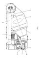
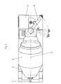
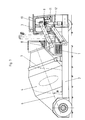
- the illustrated silo or loading vehicle serves in the Aluminum industry for charging electrolysis cells with a pourable mixture of alumina and cryolite. That through a motor 1 driven loading vehicle consists of a chassis 2, on the front side (Fig. 1 - 6) or centered (Fig. 7 - 9) a driver's pulpit 3 is arranged. Behind the driver's cockpit 3 is a silo container 4 on the chassis 2 arranged in two opposite directions Rotation directions is rotatable. The rotation of the silo container 4 takes place via a hydraulic motor 5.
- the silo container 4 is inclined in the direction of travel inclined, wherein the longitudinal axis 6 of the silo 4 with the Horizontal angle ⁇ of 20 °.
- an internal screw 7 fixed so that in one direction of rotation, the inside Snail 7 located in the silo box 4 bulk material in Direction towards the discharge end of the silo container 4 promotes. This discharge end is located at the top of the Silo container 4 just behind the driver's pulpit 3.
- the bulk material is constantly in Movement held by the silo container 4 in the direction of rotation is rotated, which is directed opposite to the direction of rotation, in which promotes the internal screw 7. This way will prevents the bulk material from vibration or impact is compressed during the journey.
- the discharge end of the silo container 4 is as swivel Head part 8 is formed, which in the horizontal by an angle ⁇ from 0 ° to 240 ° is pivotable.
- the screw conveyor system 9 consists of at least one screw disposed within a housing 10, which has a driven worm shaft with an attached Has helical thread.
- At the front end is the case of the Screw conveyor system 9 with a downward facing Abschstutzen 11 provided.
- In the starting position solid Lines in Fig. 2
- the screw conveyor system In the starting position (solid Lines in Fig. 2) is the screw conveyor system. 9 pointing obliquely in the direction of travel above the base of the Chassis 2.
- the screw conveyor system 9 can be used together with the pivotable head part 8 of the silo 4 from this Starting position pivoted by an angle ⁇ from 0 ° to 240 ° and brought to the electrolysis cell via a filling opening become.
- the bulk material contained in the silo container 4 becomes transported by the internal screw 7 to the head part 8 and via the screw conveyor 9 safely to a high promoted filling opening of the electrolysis cell.
- Of the Loading process can be monitored from the driver's cockpit 3 from become.
- the screw conveyor 9 can also be located lower Filling openings, z. B. load such at floor level or the Distribute material on the bath surface of the electrolysis cell.
- this is an open chute 12 to help taken on the side next to the driver's seat 3 on the Chassis 2 is mounted and directed downwards.
- there the entrance end of the chute 12 is below the Abschstutzens 11 of the screw conveyor system 9, if this is in the starting position.
- an open chute 12 can also be used a delivery pipe.
- the chute 12 is around an angle ⁇ pivoting, whereby the exit end of the chute 12 from the area of the chassis 2 on the bath surface of the Electrolysis cell swung out and thus the material can be evenly distributed.
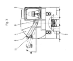
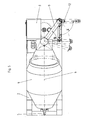
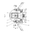
- two chutes 12 or delivery pipes be present on both sides of the Driver's pulley 3 are mounted on the chassis 2.
- the driver's cab 3 in the middle of the chassis 2 arranged.
- the two slides 12 are available with a Screw conveyor system 9, around the driver's cab 3 around is pivoted, or with two screw conveyor 9 in Connection.
- screw conveyor system can also other continuous conveyors, such as a chain conveyor, a belt conveyor or a pneumatic conveyor can be used.
Landscapes
- Engineering & Computer Science (AREA)
- Mechanical Engineering (AREA)
- Transportation (AREA)
- Health & Medical Sciences (AREA)
- Public Health (AREA)
- Structural Engineering (AREA)
- Filling Or Emptying Of Bunkers, Hoppers, And Tanks (AREA)
Abstract
Ein Silofahrzeug, insbesondere ein Beschickungsfahrzeug für Elektrolysezellen zur Herstellung von Aluminium, besteht aus einem Fahrgestell (2), einer Fahrerkanzel (3) und einem Silobehälter (4) zur Aufnahme von Material. Der Silobehälter (4) ist in Fahrtrichtung schräg ansteigend angeordnet, weist ein in Fahrtrichtung vorne liegendes Austragsende auf, ist in zwei einander entgegen gerichteten Drehrichtungen drehbar und ist mit einer innenliegenden Schnecke (7) zur Förderung des Materials zum Austragsende versehen. Das Austragsende des Silobehälters (4) besteht aus einen drehbaren Kopfteil (8), an dem ein Fördersystem befestigt ist. Dieses Fördersystem ist als angetriebener Stetigförderer ausgebildet. <IMAGE>A silo vehicle, in particular a charging vehicle for electrolysis cells for the production of aluminum, consists of a chassis (2), a driver's seat (3) and a silo container (4) for receiving material. The silo container (4) is arranged inclinedly rising in the direction of travel, has a forward discharge in the direction of travel, is rotatable in two mutually opposing directions of rotation and is provided with an internal screw (7) for conveying the material to the discharge end. The discharge end of the silo container (4) consists of a rotatable head part (8) to which a conveyor system is attached. This conveyor system is designed as a driven continuous conveyor. <IMAGE>
Description
Die Erfindung betrifft ein Silofahrzeug, insbesondere ein Beschickungsfahrzeug, für Elektrolysezellen zur Herstellung von Aluminium mit den Merkmalen des Oberbegriffes des Anspruches 1.The invention relates to a silo vehicle, in particular a Charging vehicle, for electrolysis cells for the production of Aluminum having the features of the preamble of claim 1.
Derartige Beschickungsfahrzeuge wie die Anodeneindeckfahrzeuge oder die Tonerde/Kryolith-Beschickungsfahrzeuge der Aluminiumindustrie sind Spezialfahrzeuge, die die Aufgabe haben, die Elekrolysezellen oder Elektrolyseöfen zu beschicken, wobei das Rohmaterial, nämlich das Tonerde-Kryolith-Gemisch auf der Badoberfläche verteilt wird und die Anoden bedeckt werden. Diese Fahrzeuge können einen trapezförmigen Silobehälter aufweisen, der feststehend an dem Fahrzeug angebracht ist und der über Schnecken- oder Kettenfördersysteme oder pneumatisch entleert wird. Die Entleerung des Silobehälters der Fahrzeuge erfolgt in der Regel auf Flurhöhe und bis zu einer Höhe von etwa 1 m über Flur.Such loading vehicles as the anode roofing vehicles or the alumina / cryolite feed vehicles of Aluminum industry are special vehicles that have the task to charge the Elekrolysezellen or electrolysis ovens, wherein the raw material, namely the alumina-cryolite mixture on the Bath surface is distributed and the anodes are covered. These Vehicles may have a trapezoidal silo container, which is fixedly attached to the vehicle and the over Screw or chain conveyor systems or pneumatically emptied becomes. The emptying of the silo container of the vehicles takes place in usually at ground level and up to a height of about 1 m above Hall.
Weiterhin sind mit trapezförmigen Silobehältern versehene Beschickungsfahrzeuge bekannt, welche die Zwischenspeicher von Elektrolysezellen beschicken, die mit zentralen, automatischen Verteilanlagen versehen sind. Die Nachfüllpunkte dieser Verteilanlagen befinden sich im Allgemeinen in einer Höhe von 1,5 m bis 3 m über Flur. Die Entleerung der Silobehälter ist aufgrund der zu überwindenden Höhe ausschließlich über Kettenoder Schneckentransportsysteme oder pneumatisch möglich. Dabei muss das Schüttgut jeweils von dem unteren Bereich des Silobehälters auf die benötigte Höhe gefördert werden.Furthermore, provided with trapezoidal silo containers Charging vehicles known which the buffers of Charge electrolysis cells with central, automatic Distribution systems are provided. The refill points of this Distribution systems are generally at a height of 1.5 m to 3 m above the corridor. The emptying of the silo container is due to the height to be overcome only via Kettenoder Screw transport systems or pneumatically possible. there the bulk material must be separated from the lower area of the Silo containers are conveyed to the required height.
Bei den trapezförmigen, feststehenden Silobehältern der Beschickungsfahrzeuge neigt das Schüttgut häufig zu Verklebungen oder Anbackungen im Bereich des Behälterauslaufes, zumal wenn das Schüttgut während des Transportes durch externe Vibrationen verdichtet wird. Durch diese Verklebungen und Anbackungen kann häufig kein Schüttgut aus dem Silobehälter ausgetragen werden. Dasselbe Problem tritt auch an den Schnecken- oder Kettentransportsystemen auf, die in vertikaler oder stark geneigter Lage angeordnet sind, um das Schüttgut vom Behälteraustragsende aus in die nötige Einfüllhöhe an der Elektrolysezelle zu transportieren. Verstärkt wird dieses Problem, wenn inhomogene Verunreinigungen wie z. B. Hülsen oder andere Fremdkörper im Schüttgut enthalten sind.In the case of the trapezoidal, stationary silo containers Loading vehicles often tend to stick the bulk goods to bonds or caking in the area of the container outlet, especially if the bulk material during transport due to external vibrations is compressed. Through these bonds and caking can often no bulk material is discharged from the silo container. The same problem also occurs in the snail or Chain transport systems in vertical or strong inclined position are arranged to the bulk of the Container discharge from the required filling height at the Transport electrolysis cell. This is reinforced Problem if inhomogeneous contaminants such. B. sleeves or other foreign bodies are contained in the bulk material.
Andere bekannte Beschickungsfahrzeuge (DE 198 45 573 A1) besitzen drehbare Silobehälter mit einer innenliegenden Schnecke, deren Austragsende seitlich oberhalb der Fahrerkanzel angeordnet ist. Diese Beschickungsfahrzeuge sind zur Entleerung mit einer teleskopierbaren Rutsche oder einem Förderohr versehen, die sich auf einer Seite des Fahrzeuges befindet und in einem Winkel von 20° bis 40° schwenkbar ist. Aufgrund der nach unten gerichteten Schwerkraftentladung können mit diesen Beschickungsfahrzeugen mit Hilfe der Rutsche nur Höhen bis zu 1 m über Flur beschickt werden. Größere Höhen sind vor allem deshalb nicht möglich, weil die Ofenhallen und die Transportwegen am Einsatzort nur beschränkte Fahrzeughöhen von 3 m bis maximal 3,5 m zulassen so dass ein Entleeren über Rutschen auf größere Höhen nicht möglich ist.Other known charging vehicles (DE 198 45 573 A1) own rotatable silo containers with an inside Snail, whose discharge end is laterally above the driver's cockpit is arranged. These loading vehicles are for emptying with a telescopic slide or a delivery tube provided, which is located on one side of the vehicle and is pivotable at an angle of 20 ° to 40 °. Due to the downward gravity discharge can with these Loading vehicles using the slide only heights up to 1 m be fed through the corridor. Larger heights are above all therefore not possible because the kilns and the Transport routes on site only limited vehicle heights of 3 m to a maximum of 3.5 m, allowing emptying over slides to higher altitudes is not possible.
Der Erfindung liegt die Aufgabe zugrunde, das gattungsgemäße Silo- insbesondere Beschickungsfahrzeug derart zu verbessern, dass Verklebungen und Anbackungen des Schüttguts im Silobehälter und im Fördersystem vermieden werden und dass mit einem einzigen Fahrzeug sowohl Öffnungen auf Flurhöhe als auch Zwischenspeicher in größeren Höhen beschickt werden können. The invention is based on the object, the generic Silo, in particular to improve the loading vehicle in such a way that sticking and caking of the bulk material in the silo container and be avoided in the promotion system and that with a single Vehicle both openings at floor level and cache can be loaded at higher altitudes.
Die Aufgabe wird bei einem gattungsgemäßen Silofahrzeug, insbesondere einem Beschickungsfahrzeug, erfindungsgemäß durch die kennzeichnenden Merkmale des Anspruches 1 gelöst. Vorteilhafte Ausgestaltungen der Erfindung sind Gegenstand der Unteransprüche.The object is in a generic silo vehicle, in particular a charging vehicle, according to the invention by the characterizing features of claim 1 solved. Advantageous embodiments of the invention are the subject of Dependent claims.
Das mit einem angetriebenen Stetigförderer versehene Silofahrzeug kann unter Ausnutzung der Fahrzeughöhe auch höher gelegene Einfüllöffnungen bedienen, wobei sowohl durch die innenliegende Schnecke im Silobehälter als auch aufgrund der zwangsweisen Förderung des Stetigförderers Verklebungen und Anbackungen des Schüttguts im Silobehälter und im Stetigförderer vermieden werden. Tiefer und auf Flurhöhe liegende Einfüllöffnungen können ebenfalls durch den Stetigförderer, gegebenenfalls in Verbindung mit einer nach unten gerichteten Rutsche, bedient werden.The provided with a driven continuous conveyor Silo vehicle can also be higher taking advantage of the vehicle height Serve located filling openings, both by the internal screw in the silo container as well as due to the Forced promotion of continuous conveyor bonding and Caking of the bulk material in the silo container and in the continuous conveyor be avoided. Lower and lying on ground level Einfüllöffnungen can also by the continuous conveyor, optionally in conjunction with a downward Slide, to be operated.
Mehrere Ausführungsbeispiele der Erfindung sind in der Zeichnung dargestellt und werden im Folgenden näher erläutert. Es zeigen:
- Fig. 1
- die Seitenansicht eines Beschickungsfahrzeuges,
- Fig. 2
- die Draufsicht auf das Beschickungsfahrzeug nach Fig. 1,
- Fig. 3
- die Vorderansicht des Beschickungsfahrzeuges nach Fig. 1
- Fig. 4
- die Seitenansicht eines Beschickungsfahrzeuges gemäß einer anderen Ausführungsform,
- Fig. 5
- die Draufsicht auf das Beschickungsfahrzeug nach Fig. 4,
- Fig. 6
- die Vorderansicht des Beschickungsfahrzeuges nach Fig. 4
- Fig. 7
- die Seitenansicht eines Beschickungsfahrzeuges gemäß einer weiteren Ausführungsform,
- Fig. 8
- die Draufsicht auf das Beschickungsfahrzeug nach Fig. 7 und
- Fig. 9
- die Vorderansicht des Beschickungsfahrzeuges nach Fig. 7
- Fig. 1
- the side view of a loading vehicle,
- Fig. 2
- the top view of the loading vehicle of FIG. 1,
- Fig. 3
- the front view of the loading vehicle of FIG. 1
- Fig. 4
- the side view of a loading vehicle according to another embodiment,
- Fig. 5
- the top view of the loading vehicle of FIG. 4,
- Fig. 6
- the front view of the loading vehicle of FIG. 4th
- Fig. 7
- the side view of a loading vehicle according to another embodiment,
- Fig. 8
- the top view of the feed vehicle of FIG. 7 and
- Fig. 9
- the front view of the loading vehicle of FIG. 7
Das dargestellte Silo- oder Beschickungsfahrzeug dient in der
Aluminiumindustrie zur Beschickung von Elektrolysezellen mit
einem schüttfähigen Gemisch aus Tonerde und Kryolith. Das durch
einen Motor 1 angetriebene Beschickungsfahrzeug besteht aus
einem Fahrgestell 2, auf dem vorne seitlich (Fig. 1 - 6) oder
mittig (Fig. 7 - 9) eine Fahrerkanzel 3 angeordnet ist. Hinter
der Fahrerkanzel 3 ist auf dem Fahrgestell 2 ein Silobehälter 4
angeordnet, der in zwei einander entgegengerichteten
Drehrichtungen drehbar ist. Die Drehung des Silobehälters 4
erfolgt über einen Hydraulikmotor 5.The illustrated silo or loading vehicle serves in the
Aluminum industry for charging electrolysis cells with
a pourable mixture of alumina and cryolite. That through
a motor 1 driven loading vehicle consists of
a
Der Silobehälter 4 ist in Fahrtrichtung schräg ansteigend
geneigt, wobei die Längsachse 6 des Silobehälters 4 mit der
Horizontalen einen Winkel α von 20° einschließt. An der
Innenwand des Silobehälters 4 ist eine innenliegende Schnecke 7
so befestigt, dass bei einer Drehrichtung die innenliegende
Schnecke 7 das im Silobehälter 4 befindliche Schüttgut in
Richtung auf das Austragsende des Silobehälters 4 fördert.
Dieses Austragsende befindet sich an dem oberen Ende des
Silobehälters 4 gerade hinter der Fahrerkanzel 3. Während der
Fahrt des Beschickungsfahrzeuges wird das Schüttgut ständig in
Bewegung gehalten, indem der Silobehälter 4 in der Drehrichtung
gedreht wird, die der Drehrichtung entgegen gerichtet ist, in
der die innenliegende Schnecke 7 fördert. Auf diese Weise wird
verhindert, dass das Schüttgut durch Vibration oder Stöße
während der Fahrt verdichtet wird.The
Das Austragsende des Silobehälters 4 ist als schwenkbares
Kopfteil 8 ausgebildet, das in der Horizontalen um einen Winkel β
von 0° bis 240° schwenkbar ist. An dem schwenkbaren Kopfteil 8
ist ein Schneckenfördersystem 9 befestigt, das gegen die
Horizontale um einen Winkel von δ = 15° schräg nach oben
gerichtet ist. Das Schneckenfördersystem 9 besteht aus
mindestens einer innerhalb eines Gehäuses angeordneten Schnecke
10, die eine angetriebene Schneckenwelle mit einem aufgesetzten
Schneckengang aufweist. Am vorderen Ende ist das Gehäuse des
Schneckenfördersystems 9 mit einem nach unten weisenden
Abwurfstutzen 11 versehen. In der Ausgangslage (ausgezogene
Linien in Fig. 2) befindet sich das Schneckenfördersystem 9
schräg in Fahrtrichtung weisend oberhalb der Grundfläche des
Fahrgestells 2. Das Schneckenfördersystem 9 kann zusammen mit
dem schwenkbaren Kopfteil 8 des Silobehälters 4 aus dieser
Ausgangslage um einen Winkel β von 0° bis 240° geschwenkt und
über eine Einfüllöffnung an der Elektrolysezelle gebracht
werden. Das in dem Silobehälter 4 befindliche Schüttgut wird
durch die innenliegende Schnecke 7 zum Kopfteil 8 transportiert
und über das Schneckenfördersystem 9 sicher zu einer hoch
gelegenen Einfüllöffnung der Elektrolysezelle gefördert. Der
Beschickungsvorgang kann von der Fahrerkanzel 3 aus überwacht
werden.The discharge end of the
Das Schneckenfördersystem 9 kann auch tiefer gelegene
Einfüllöffnungen, z. B. solche auf Flurhöhe beschicken oder das
Material auf der Badoberfläche der Elektrolysezelle verteilen.
Vorzugsweise wird hierzu eine offene Rutsche 12 zu Hilfe
genommen, die seitlich neben der Fahrerkanzel 3 auf dem
Fahrgestell 2 angebracht und nach unten gerichtet ist. Dabei
liegt das Eintrittsende der Rutsche 12 unterhalb des
Abwurfstutzens 11 des Schneckenfördersystems 9, wenn sich dieses
in der Ausgangslage befindet. Anstelle einer offenen Rutsche 12
kann auch ein Förderrohr verwendet werden. Die Rutsche 12 ist um
einen Winkel γ schwenkbar, wodurch das Austrittsende der Rutsche
12 aus dem Bereich des Fahrgestells 2 über die Badoberfläche der
Elektrolysezelle herausgeschwenkt und somit das Material
gleichmäßig verteilt werden kann. Auch in diesem Fall kann der
Beschickungsvorgang von der Fahrerkanzel 3 aus beobachtet
werden. Da das beschriebene Schneckenfördersystem 9 Verklebungen
und Anbackungen des Schüttguts im Schneckenfördersystem
vermeidet, ist der Einsatz einer Schwerkraftförderung über die
Rutsche 12 oder das Förderrohr in Verbindung mit diesem
Schneckenfördersystem 9 unproblematisch.The
Wie in den Fig. 7 - 9 gezeigt ist, können auch zwei Rutschen 12
oder Förderrohre vorhanden sein, die beiderseits der
Fahrerkanzel 3 auf dem Fahrgestell 2 angebracht sind. In diesem
Fall ist die Fahrerkanzel 3 mittig auf dem Fahrgestell 2
angeordnet. Die beiden Rutschen 12 stehen mit einem
Schneckenfördersystem 9, das um die Fahrerkanzel 3 herum
geschwenkt wird, oder mit zwei Schneckenfördersystemen 9 in
Verbindung.As shown in FIGS. 7-9, two
Anstelle des beschriebenen Schneckenfördersystems kann auch ein anderer Stetigförderer, wie ein Kettenförderer, ein Gurtförderer oder ein pneumatischer Förderer eingesetzt werden.Instead of the described screw conveyor system can also other continuous conveyors, such as a chain conveyor, a belt conveyor or a pneumatic conveyor can be used.
Claims (8)
Applications Claiming Priority (2)
| Application Number | Priority Date | Filing Date | Title |
|---|---|---|---|
| DE10342235 | 2003-09-11 | ||
| DE2003142235 DE10342235A1 (en) | 2003-09-11 | 2003-09-11 | Silo vehicle, in particular loading vehicle |
Publications (2)
| Publication Number | Publication Date |
|---|---|
| EP1514728A2 true EP1514728A2 (en) | 2005-03-16 |
| EP1514728A3 EP1514728A3 (en) | 2006-03-15 |
Family
ID=34129788
Family Applications (1)
| Application Number | Title | Priority Date | Filing Date |
|---|---|---|---|
| EP04021258A Withdrawn EP1514728A3 (en) | 2003-09-11 | 2004-09-08 | Silo-vehicle, specially supplying vehicle |
Country Status (5)
| Country | Link |
|---|---|
| EP (1) | EP1514728A3 (en) |
| CA (1) | CA2481132A1 (en) |
| DE (1) | DE10342235A1 (en) |
| NO (1) | NO20043806L (en) |
| ZA (1) | ZA200407120B (en) |
Family Cites Families (8)
| Publication number | Priority date | Publication date | Assignee | Title |
|---|---|---|---|---|
| US2859949A (en) * | 1955-07-18 | 1958-11-11 | Willard J Jack | Forward discharging transit concrete mixer |
| US2883076A (en) * | 1958-04-14 | 1959-04-21 | Harold S Palmer | Material handling system |
| US3633879A (en) * | 1969-05-01 | 1972-01-11 | Challenge Cook Bros Inc | Concrete transit mixer with forward discharge mechanism |
| DE2701699A1 (en) * | 1977-01-17 | 1978-07-20 | Louis Amour | Vehicle mounted folding endless conveyor belt - has slewing spindle in bearing on chassis and formed with support yoke |
| IT1098239B (en) * | 1978-08-09 | 1985-09-07 | Cie Italiana Forne Acciaio Spa | TRUCK MIXER SUITABLE FOR CONSENIATION SUITABLE FOR ALLOWING THE DRIVER DIRECT VISUAL CONTROL OF THE CONCRETE LOADING AND UNLOADING OPERATIONS |
| DE3331314A1 (en) * | 1983-08-31 | 1985-10-03 | Hellmut 2104 Hamburg Hupfeld | Transport mixer for mixable construction materials |
| DE19845573A1 (en) * | 1998-10-02 | 2000-04-06 | Vaw Ver Aluminium Werke Ag | Silo-vehicle consisting of chassis and travelling screen also silo container which is arranged inclined in travel direction so that longitudinal axis is raised in travel direction |
| DE20021668U1 (en) * | 2000-12-21 | 2001-03-08 | Liebherr-Mischtechnik Gmbh, 88427 Bad Schussenried | Vehicle, preferably truck mixer, with a pivotable conveyor belt attached to the vehicle frame |
-
2003
- 2003-09-11 DE DE2003142235 patent/DE10342235A1/en not_active Ceased
-
2004
- 2004-09-07 ZA ZA200407120A patent/ZA200407120B/en unknown
- 2004-09-08 EP EP04021258A patent/EP1514728A3/en not_active Withdrawn
- 2004-09-10 NO NO20043806A patent/NO20043806L/en unknown
- 2004-09-10 CA CA 2481132 patent/CA2481132A1/en not_active Abandoned
Also Published As
| Publication number | Publication date |
|---|---|
| CA2481132A1 (en) | 2005-03-11 |
| DE10342235A1 (en) | 2005-04-07 |
| ZA200407120B (en) | 2004-11-08 |
| NO20043806L (en) | 2005-03-14 |
| EP1514728A3 (en) | 2006-03-15 |
Similar Documents
| Publication | Publication Date | Title |
|---|---|---|
| DE69108638T2 (en) | Device and method for unloading bulk goods. | |
| DE3390301C2 (en) | Method and device for the transport of powdery or particulate material | |
| DE3422569C2 (en) | ||
| DE7730505U1 (en) | MOBILE UNLOADING DEVICE FOR BULK GOODS | |
| DE3390175C2 (en) | ||
| DE8704215U1 (en) | Device for transporting and storing bulk building materials on site | |
| DE1940714A1 (en) | Device for discharging bulk goods from silos | |
| EP0658409B1 (en) | Mixing machine | |
| DE19960118C2 (en) | Mixing device for mobile grinding and mixing plants | |
| EP1514728A2 (en) | Silo-vehicle, specially supplying vehicle | |
| DE3426806C2 (en) | Silo with a circular outline for bulk goods and a cross conveyor that can be raised and lowered on a support column | |
| DE2057064B2 (en) | Device for supplying e.g. plastering machines set up on different floors of a building or the like | |
| DE7908438U1 (en) | ISO CONTAINER FOR POWDERED MELAMINE | |
| DE19724504A1 (en) | Two-cylinder nitrogen pump | |
| DE3429023C2 (en) | ||
| DE4413699C2 (en) | Containers for bulk and viscous goods | |
| EP0429693B1 (en) | Storage tank | |
| DE3604474C2 (en) | ||
| DE568864C (en) | Conveyor device for bulk goods, consisting of a rotatably mounted conveyor tube, in the interior of which there is a conveyor screw firmly connected to the tube | |
| DE1914382A1 (en) | Garbage truck | |
| AT15104U2 (en) | Mobile device for crushing lumpy goods | |
| DE9405653U1 (en) | Device for connecting a stationary bulk material source to a charging device which can be moved along a predetermined loading path | |
| AT243149B (en) | Device for charging car mixers or the like with building materials | |
| AT383334B (en) | DEVICE FOR THE INLET AND OUTLET AND THE EVEN DISTRIBUTION OF PUBLIC GOODS, IN PARTICULAR FLASH BAG, IN A TANK | |
| EP0427931A1 (en) | Discharge installation for a bulk silo |
Legal Events
| Date | Code | Title | Description |
|---|---|---|---|
| PUAI | Public reference made under article 153(3) epc to a published international application that has entered the european phase |
Free format text: ORIGINAL CODE: 0009012 |
|
| AK | Designated contracting states |
Kind code of ref document: A2 Designated state(s): AT BE BG CH CY CZ DE DK EE ES FI FR GB GR HU IE IT LI LU MC NL PL PT RO SE SI SK TR |
|
| AX | Request for extension of the european patent |
Extension state: AL HR LT LV MK |
|
| PUAL | Search report despatched |
Free format text: ORIGINAL CODE: 0009013 |
|
| AK | Designated contracting states |
Kind code of ref document: A3 Designated state(s): AT BE BG CH CY CZ DE DK EE ES FI FR GB GR HU IE IT LI LU MC NL PL PT RO SE SI SK TR |
|
| AX | Request for extension of the european patent |
Extension state: AL HR LT LV MK |
|
| RIC1 | Information provided on ipc code assigned before grant |
Ipc: B28C 5/42 20060101ALI20060123BHEP Ipc: B60P 3/16 20060101AFI20041221BHEP |
|
| AKX | Designation fees paid | ||
| STAA | Information on the status of an ep patent application or granted ep patent |
Free format text: STATUS: THE APPLICATION IS DEEMED TO BE WITHDRAWN |
|
| 18D | Application deemed to be withdrawn |
Effective date: 20060916 |
|
| REG | Reference to a national code |
Ref country code: DE Ref legal event code: 8566 |