EP1514656B9 - Kraftwerkzeug - Google Patents
Kraftwerkzeug Download PDFInfo
- Publication number
- EP1514656B9 EP1514656B9 EP04020453A EP04020453A EP1514656B9 EP 1514656 B9 EP1514656 B9 EP 1514656B9 EP 04020453 A EP04020453 A EP 04020453A EP 04020453 A EP04020453 A EP 04020453A EP 1514656 B9 EP1514656 B9 EP 1514656B9
- Authority
- EP
- European Patent Office
- Prior art keywords
- motor
- tool
- rotating tool
- saw
- brake
- Prior art date
- Legal status (The legal status is an assumption and is not a legal conclusion. Google has not performed a legal analysis and makes no representation as to the accuracy of the status listed.)
- Expired - Lifetime
Links
Images









Classifications
-
- B—PERFORMING OPERATIONS; TRANSPORTING
- B23—MACHINE TOOLS; METAL-WORKING NOT OTHERWISE PROVIDED FOR
- B23Q—DETAILS, COMPONENTS, OR ACCESSORIES FOR MACHINE TOOLS, e.g. ARRANGEMENTS FOR COPYING OR CONTROLLING; MACHINE TOOLS IN GENERAL CHARACTERISED BY THE CONSTRUCTION OF PARTICULAR DETAILS OR COMPONENTS; COMBINATIONS OR ASSOCIATIONS OF METAL-WORKING MACHINES, NOT DIRECTED TO A PARTICULAR RESULT
- B23Q11/00—Accessories fitted to machine tools for keeping tools or parts of the machine in good working condition or for cooling work; Safety devices specially combined with or arranged in, or specially adapted for use in connection with, machine tools
- B23Q11/0078—Safety devices protecting the operator, e.g. against accident or noise
- B23Q11/0092—Safety devices protecting the operator, e.g. against accident or noise actuating braking or stopping means
-
- B—PERFORMING OPERATIONS; TRANSPORTING
- B23—MACHINE TOOLS; METAL-WORKING NOT OTHERWISE PROVIDED FOR
- B23D—PLANING; SLOTTING; SHEARING; BROACHING; SAWING; FILING; SCRAPING; LIKE OPERATIONS FOR WORKING METAL BY REMOVING MATERIAL, NOT OTHERWISE PROVIDED FOR
- B23D59/00—Accessories specially designed for sawing machines or sawing devices
- B23D59/001—Measuring or control devices, e.g. for automatic control of work feed pressure on band saw blade
-
- B—PERFORMING OPERATIONS; TRANSPORTING
- B27—WORKING OR PRESERVING WOOD OR SIMILAR MATERIAL; NAILING OR STAPLING MACHINES IN GENERAL
- B27B—SAWS FOR WOOD OR SIMILAR MATERIAL; COMPONENTS OR ACCESSORIES THEREFOR
- B27B5/00—Sawing machines working with circular or cylindrical saw blades; Components or equipment therefor
- B27B5/29—Details; Component parts; Accessories
- B27B5/38—Devices for braking the circular saw blade or the saw spindle; Devices for damping vibrations of the circular saw blade, e.g. silencing
-
- B—PERFORMING OPERATIONS; TRANSPORTING
- B27—WORKING OR PRESERVING WOOD OR SIMILAR MATERIAL; NAILING OR STAPLING MACHINES IN GENERAL
- B27G—ACCESSORY MACHINES OR APPARATUS FOR WORKING WOOD OR SIMILAR MATERIALS; TOOLS FOR WORKING WOOD OR SIMILAR MATERIALS; SAFETY DEVICES FOR WOOD WORKING MACHINES OR TOOLS
- B27G19/00—Safety guards or devices specially adapted for wood saws; Auxiliary devices facilitating proper operation of wood saws
- B27G19/008—Safety guards or devices specially adapted for wood saws; Auxiliary devices facilitating proper operation of wood saws with sensing of human contact or proximity with the blade
-
- B—PERFORMING OPERATIONS; TRANSPORTING
- B27—WORKING OR PRESERVING WOOD OR SIMILAR MATERIAL; NAILING OR STAPLING MACHINES IN GENERAL
- B27G—ACCESSORY MACHINES OR APPARATUS FOR WORKING WOOD OR SIMILAR MATERIALS; TOOLS FOR WORKING WOOD OR SIMILAR MATERIALS; SAFETY DEVICES FOR WOOD WORKING MACHINES OR TOOLS
- B27G19/00—Safety guards or devices specially adapted for wood saws; Auxiliary devices facilitating proper operation of wood saws
- B27G19/02—Safety guards or devices specially adapted for wood saws; Auxiliary devices facilitating proper operation of wood saws for circular saws
-
- F—MECHANICAL ENGINEERING; LIGHTING; HEATING; WEAPONS; BLASTING
- F16—ENGINEERING ELEMENTS AND UNITS; GENERAL MEASURES FOR PRODUCING AND MAINTAINING EFFECTIVE FUNCTIONING OF MACHINES OR INSTALLATIONS; THERMAL INSULATION IN GENERAL
- F16P—SAFETY DEVICES IN GENERAL; SAFETY DEVICES FOR PRESSES
- F16P3/00—Safety devices acting in conjunction with the control or operation of a machine; Control arrangements requiring the simultaneous use of two or more parts of the body
- F16P3/12—Safety devices acting in conjunction with the control or operation of a machine; Control arrangements requiring the simultaneous use of two or more parts of the body with means, e.g. feelers, which in case of the presence of a body part of a person in or near the danger zone influence the control or operation of the machine
- F16P3/14—Safety devices acting in conjunction with the control or operation of a machine; Control arrangements requiring the simultaneous use of two or more parts of the body with means, e.g. feelers, which in case of the presence of a body part of a person in or near the danger zone influence the control or operation of the machine the means being photocells or other devices sensitive without mechanical contact
- F16P3/147—Safety devices acting in conjunction with the control or operation of a machine; Control arrangements requiring the simultaneous use of two or more parts of the body with means, e.g. feelers, which in case of the presence of a body part of a person in or near the danger zone influence the control or operation of the machine the means being photocells or other devices sensitive without mechanical contact using electro-magnetic technology, e.g. tags or radar
Definitions
- the present invention relates to power tools. Specifically, it relates to techniques for preventing, as far as possible, an object other than a work from making contact with a rotating tool.
- WO-A-96/37350 discloses a power tool in accordance with the preamble of claims 1 and 7.
- U.S. unexamined patent application No. 17336/2002 sets forth a power tool that performs an emergency stop of the tool's rotation when an operator's hand has made contact with the rotating tool.
- This power tool utilizes the difference of the electric conductivity between human beings and work (wood).
- the electric potential of the rotating tool becomes higher when the operator's hand makes contact with the rotating tool than the electric potential of the rotating tool when the work (wood) makes contact with the rotating tool.
- the power tool detects timing when the operator's hand makes contact with the rotating tool.
- the power tool performs an emergency stop of the tool's rotation when the electric potential of the rotating tool becomes higher than a predetermined level. Alternatively, the rotating tool is caused to rapidly retreat to a safe zone.
- the above-described known power tool halts the rotation of the tool or retreats the rotating tool to a safe zone, only after contact between the operator's hand and the rotating tool has been detected. It is not possible to prevent the operator's hand from making contact with the tool under rotation. Consequently, the tool's rotation must be halted, or the rotating tool must be retreated within an extremely short period. This requires a large-scale braking means or retreating means. This technique is very difficult to apply to small-scale power tools such as portable models. Further, troublesome resetting operations are required to recover the power tool to a normal condition once the emergency stopping system is activated.
- the situation may be detected by monitoring the distance between the rotating tool and the object, and the speed of the object moving toward the rotating tool.
- a typical appropriate measure may be activating a brake for the rotating tool. By activating the brake prior to the contact, it becomes possible to stop the rotation of the tool before the object has made contact with the tool.
- distance in the first criterion and the second criterion increases as speed increases.
- the distance corresponding to a certain speed in the first criterion is preferably longer than the distance corresponding to the same speed in the second criterion.
- the power tool to continue operation when the situation having high likelihood of contact has ceased. Frequent emergency stopping may be avoided and efficient and comfortable operation of the power tool may be continued.
- the radio wave reflector such as an operator's hand
- the first brake is activated and a gentle braking force is applied to the rotating tool.
- the second brake is activated and a rapid braking force is applied to the rotating tool.
- the rotation of the tool may be already stopped, thereby preventing the object from making contact with the tool under rotation.
- the distance when the first brake is activated is longer when the speed of the object is faster.
- the distance when the second brake is activated is longer when the speed of the object is faster.
- the distance corresponding to a certain speed of the object in the first criterion is longer than distance corresponding to the same speed in the second criterion.
- the first criterion is fulfilled at a longer distance than the distance at which the second criterion is fulfilled.
- the first brake is activated prior to the activation of the second brake.
- the object approaches to the rotating tool until the first criterion is fulfilled, however the object retreats from the rotating tool before the second criterion is fulfilled.
- the rapid braking is not activated and the operator may continue the operation of the power tool without being interrupted.
- radio wave reflection coefficients vary according to type of material.
- Work wood
- Work wood
- a radar may detect a radio wave reflector in the area hidden by the work. Using the radar, the distance from the radar to the radio wave reflector can be detected.
- the distance between the radio wave reflector and the rotating tool By detecting the distance at particular points in time, it is possible to detect the speed at which this distance changes. That is, it is possible to detect the speed of movement at which the radio wave reflector is moving towards the rotating tool.
- the speed of movement at which the radio wave reflector is moving towards the rotating tool may also be detected directly by using a radar that detects the Doppler effect.
- the likelihood that the radio wave reflector will make contact with the rotating tool may be calculated from the distance thereof from the rotating tool together with its speed of movement towards the rotating tool. If there is rapid movement towards the rotating tool, there is a high likelihood of the radio wave reflector making contact with the rotating tool even if the radio wave reflector is a long distance away.
- the radio wave reflector If there is no rapid movement towards the rotating tool, there is a low likelihood of the radio wave reflector making contact with the rotating tool (as long as the radio wave reflector is not a short distance from the rotating tool). Accordingly, criteria which are based on the combination of distance and speed are utilized to detect an occurrence of a situation having high likelihood of contact between the radio wave reflector and the rotating tool.
- the power tool may start necessary measures at the time when the occurrences are detected.
- a power tool of the present teachings first applies gentle braking and thereby reduces inertial energy, and then applies rapid braking. Rapid braking, when applied after inertial energy has been reduced, exerts no particularly heavy load on the brake, and no particularly strong counter force is exerted on the power tool and on the support that is supporting the power tool. It is comparatively easy to provide a brake and a support capable of withstanding this load and counter force.
- a power tool in accordance with the invention may utilize a combination of a first brake for applying gentle braking and a second brake for applying rapid braking.
- Each brake may be activated based upon each criterion.
- Each criterion may be defined by the combination of distance and speed.
- Braking systems are activated in a sequence of the first brake and the second brake when there is a high likelihood that the radio wave reflector will make contact with the rotating tool.
- a one-way clutch is inserted between the rotating tool and a motor for causing the tool to rotate, this one-way clutch causing the rotating tool and the motor to be in a disengaged state in a case where the rotation speed at the motor side is slower than the rotation speed at the rotating tool side.
- the first brake applies braking force to a component at the motor side of the one-way clutch
- the second brake applies braking force to a component at the rotating tool side of the one-way clutch.
- the inertia energy of the motor is greater than that of the rotating tool.
- the motor side component receives braking force and the rotation speed at the motor side is reduced, the one-way clutch allows the tool to continue rotation at high speed. Meanwhile, the rotation speed at the motor side continues to fall. If the radio wave reflector comes closer to the rotating tool, thereby fulfilling the second criterion, the second brake operates to apply rapid braking force to the rotating tool. At this point, the rotation speed at the motor side has already been reduced and the one-way clutch is rotating idly. Consequently, the second brake needs to brake only the components at the rotating tool side. These have a small inertia energy, and consequently rapid braking is possible. There is a possibility that the rotation speed at the motor side will catch up while the components at the rotating tool side are being braked rapidly. In that case, the motor is also rapidly braked by the second brake. However, at this juncture, the motor has already slowed down and inertia energy thereof has decreased, so that the rapid braking of the motor does not create any problem.
- the first brake is realized as a regenerative brake that brakes the electric motor by causing the electric motor to generate electric power.
- the configuration of the device can thus be simpler than in the case where a mechanical brake is adopted.
- a clutch may be inserted between the rotating tool and a motor for causing the tool to rotate, the clutch being capable of switching the rotating tool and the motor between an engaged state and a disengaged state.
- the first brake by switching the clutch to the disengaged state, causes a state wherein a braking force is applied to the rotating tool by means of friction generated between the rotating tool and work, and the second brake applies braking force to a component at the rotating tool side of the clutch.
- strong friction is generated between the rotating tool and the work while the work is being processed. The present power tool effectively utilizes this friction.
- the above-noted objects are also achieved by the power tool of claim 7.
- Distance in the first criterion and the second criterion increases as speed increases according to preferred embodiments of the present invention, and distance corresponding to a certain speed in the first criterion is longer than distance corresponding to the same speed in the second criterion.
- the term 'motor' is not restricted to electric motors, but also encompasses motors that rotate by means of compressed air, motors that rotate by means of ultrasonic waves, motors that rotate by engines, etc.
- the power tool of claim 7 also uses the first criterion to detect the likelihood that the radio wave reflector will make contact with the rotating tool.
- the clutch is caused to be in a disengaged state at this period.
- the tool and the motor are thereby caused to be in an independent state wherein they rotate freely, and it is then observed whether the second criterion has been fulfilled. If the first criterion is no longer fulfilled and the second criterion has not been fulfilled, the clutch reassumes the engaged state and operations can continue. If the radio wave reflector approaches sufficiently for the second criterion to be fulfilled, the tool brake applies braking force to the rotating tool. At this point, the clutch had been disengaged.
- the tool brake can rapidly brake the rotation of the tool.
- the rotation of the tool is rapidly halted in this power tool. This consequently reduces the risk that the radio wave reflector such as a hand of an operator will make contact with the tool under rotation.
- braking is rapid, the tool and the motor have already been disengaged by the clutch. Consequently no particularly heavy load is exerted on the tool brake, and no particularly strong counter force is exerted on the power tool and on the support that is supporting the power tool.
- the configuration of the brake is simplified, and the durability thereof is improved.
- the aforementioned clutch can be, for example, an electromagnetic power clutch, a pneumatic clutch, etc.
- a centrifugal clutch can also be utilized in combination with a brake for braking the motor side componets.
- the centrifugal clutch causes the motor and the tool to be in an engaged state.
- the centrifugal clutch causes the motor and the tool to be in a disengaged state.
- the transmission of power between the motor and the tool can thus be cut off by braking the motor side componets.
- this centrifugal clutch is utilized, the motor does not need to be halted, but needs to be braked only to the extent that the centrifugal clutch achieves the disengaged state.
- radio waves are utilized that readily penetrate wooden material and are readily reflected from objects made of metal and from objects having a high moisture content. These characteristics can be obtained by utilizing radio waves having a frequency of 1 to 30 GHz. It is thus possible to prevent, as far as possible, the occurrence of phenomena such as the radar wrongly identifying work and thus causing unnecessary emergency braking. It is also possible to prevent the radar from failing to detect the radio wave reflector that is hidden in the shadow of work. Emergency braking is activated when necessary.
- the braking of the rotating tool is not restricted to braking wherein braking force is applied directly to the rotating tool.
- Braking of the rotation may be any actions that result in the braking of the rotation of the tool.
- the rotating tool is also braked by applying braking force to components joined with the rotating tool, such as a tool shaft.
- the present power tool prevents, as far as possible, a radio wave reflector other than a work from making contact with a rotating tool.
- a radio wave reflector other than a work it is possible to detect a state wherein it is likely that the radio wave reflector other than the work will make contact with the rotating tool before actual contact occurs.
- the operation of the rotating tool can be braked in response to this state. Consequently, there is a high likelihood that the rotation of the tool can be halted before the object other than the work makes contact with the tool.
- the table saw 1 illustrated in FIGS. 1 and 2 is developed in accordance with the present teaching.
- the table saw 1 is a power tool designed for cutting wooden work W.
- the table saw 1 is provided with a table 5 on which the work W is placed, a circular saw 3 having a portion thereof protruding above the table 5, and a safety cover 7 that covers the protruding portion of the circular saw 3.
- the safety cover 7 is rotatably attached above the table 5 and is pushed open by the work W during cutting.
- the table saw 1 is provided with a motor 11 for driving the circular saw 3, a power transmission member 13 for transmitting power from the motor 11 to the circular saw 3, and a controlling member 15 for controlling the operation of the table saw 1. Electricity is supplied to the table saw 1 from a power supply cord 19.
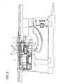
- FIG. 3 is a partial cross-sectional view of the table saw 1 showing the configuration for transmitting the power from the motor 11 to the circular saw 3 via the power transmission member 13.
- a gear 12a is formed around a rotating shaft 12 of the motor 11.
- the power transmission member 13 is provided with a gear 21 that engages with the gear 12a of the rotating shaft 12, a saw shaft 27 that is rotatably supported on the same axis as the gear 21, and a one-way clutch 29 inserted between an inner hole face of the gear 21 and an outer circumference face of the saw shaft 27.
- the circular saw 3 is fixed to the saw shaft 27, by means of attaching plates 23a and 23b and an attaching bolt 25, etc., at a positioning extending from the power transmission member 13.
- the one-way clutch 29 is a clutch that, when the circular saw 3 is rotating in the normal direction of rotation, separates the gear 21 and the saw shaft 27 when the rotation speed of the gear 21 is slower than the rotation speed of the saw shaft 27. Consequently, the rotation speed of the saw shaft 27 is usually greater than or equal to the rotation speed of the gear 21, and the saw shaft 27 rotates idly when the rotation speed of the saw shaft 27 is greater than the rotation speed of the gear 21.
- the one-way clutch 29 can be a clutch wherein sprags, for example, balls, rollers, etc.
- the clutch can be chosen to meet requirements, and is not restricted to a particular type.
- the rotational power of the rotating shaft 12 is transmitted to the gear 21 when the motor 11 rotates.
- the one-way clutch 29 is selected to the engaged state, and the saw shaft 27 is rotated. This transmits the rotational power of the motor 11 to the saw shaft 27.
- the circular saw 3 rotates together with the saw shaft 27, and a user (operator) of the table saw 1 is able to perform cutting operations of the work W.
- the rotation speed of the rotating shaft 12 decreases. Thereupon the rotation speed of the saw shaft 27 becomes greater than the rotation speed of the gear 21, and the saw shaft 27 begins to rotate idly.
- an expanded diameter member 28 is formed on the saw shaft 27.
- the expanded diameter member 28 and the saw shaft 27 may be molded integrally, or may be molded as separate components and fixed together.
- the expanded diameter member 28 and the saw shaft 27 should not rotate relative to one another.
- a saw shaft brake 31 is provided at a peripheral position of the expanded diameter member 28 of the saw shaft 27.
- the saw shaft brake 31 is formed mainly from a sliding block 33, a locking pin 37, and a solenoid 38, etc. As shown in FIG.
- the saw shaft brake 31 consists of the sliding block 33 that is slid during operation to make contact with the expanded diameter member 28 of the saw shaft 27, a spring 35 for causing the sliding block 33 to slide, the locking pin 37 for restraining the sliding block 33 in a waiting position, the solenoid 38 that withdraws the locking pin 37 from the sliding block 33, etc. Further, the saw shaft brake 31 is provided with a pushing rod 39 that pushes the sliding block 33 back to the waiting position, and a spring 39a that energizes the pushing rod 39 to the waiting position. A face 33b of the sliding block 33 is formed in an inclined wedge shape. This face 33b makes contact with the expanded diameter member 28. FIG. 4 shows a state wherein the saw shaft brake 31 is not operating.
- the sliding block 33 is in the waiting position wherein it does not make contact with the expanded diameter member 28 of the saw shaft 27.
- the spring 35 is thoroughly compressed, and the resilient force of the spring 35 is operating upon the sliding block 33.
- This resilient force is a force capable of sliding the sliding block 33 to a position wherein it makes contact with the expanded diameter member 28.
- the locking pin 37 engages with a hole 33a provided in the sliding block 33, thereby restraining the sliding block 33 in the waiting position.
- the locking pin 37 is connected with a needle 38a of the solenoid 38.
- the solenoid 38 keeps the needle 38a protruding when power is not passing therethrough.
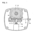
- FIG. 5 shows the saw shaft brake 31 in an operating state.
- Operating the solenoid 38 causes the saw shaft brake 31 to start operation.
- the protruding needle 38a is rapidly withdrawn.
- the locking pin 37 that is connected with the needle 38a is withdrawn from the hole 33a of the sliding block 33.
- the sliding block 33 is thereby released from its restraint by the locking pin 37, and is slid by the resilient force of the spring 35 towards a position whereby it makes contact with the expanded diameter member 28.
- the friction between the sliding block 33 and the expanded diameter member 28 brakes the saw shaft 27.
- the sliding block 33 is pulled further inwards by the friction with the expanded diameter member 28, and the frictional force between the sliding block 33 and the expanded diameter member 28 increases, thereby more strongly braking the saw shaft 27. That is, the rotating circular saw 3 is rapidly halted. Halting the flow of the power through the solenoid 38 and pushing in the pushing rod 39 returns the saw shaft brake 31 to its original state after operation. The pushing rod 39 pushes the sliding block 33 back to the waiting position. When the sliding block 33 is moved to the waiting position, the needle 38a of the solenoid 38 engages with the hole 33a. The saw shaft 27 may be caused to rotate in the reverse direction when the sliding block 33 strongly makes contact with the expanded diameter member 28. By this means, the saw shaft brake 31 can easily be returned to its original state after operation.
- a first radar 46 and a second radar 47 are located at the anterior and posterior respectively of the circular saw 3.
- the first radar 46 monitors a first prescribed area A that is in the vicinity of a location where a blade edge of the circular saw 3 and the work W make contact (a processing location).
- the first prescribed area A is shown in FIG. 6 (the hatched area at the lower right).
- FIG. 6 is a schematic view, viewed from above, of the vicinity of the circular saw 3 of the table saw 1.
- the first radar 46 is located to the anterior of the circular saw 3 below the table 5. Since the first radar 46 is provided below the table 5, a penetrable window 5a through which radio waves penetrate is provided in the table 5 near the anterior edge of the circular saw 3 (see FIG.
- the penetrable window 5a can be formed from a resin plate.
- the second radar 47 is a radar for monitoring a second prescribed area B that extends along the circular saw 3 in the direction in which work is sent.
- the second prescribed area B is shown in FIG. 6.
- the first prescribed area A is encompassed within the second prescribed area B.
- the second radar 47 is attached to the tip of an arm 45 provided at the posterior of the table 5.
- the second radar 47 is located above and to the posterior of the circular saw 3 (the side opposite the operator).
- the second radar 47 is located such that the center thereof is above the surface of the circular saw 3. This minimizes the area of shadow of the circular saw 3 that the second radar 47 is confronted with.
- the first radar 46 will be described in more detail.
- the first radar 46 is provided with a transmitting and receiving antenna 54 for transmitting and receiving radio waves.
- An oscillation circuit 52 for outputting an electrical signal oscillated at a specified frequency is connected with the transmitting and receiving antenna 54 (specifically, with a radio wave transmitting member of the transmitting and receiving antenna 54).
- a clock circuit 50 is connected with the oscillation circuit 52.
- the clock circuit 50 is a circuit for periodically causing the output of the oscillation circuit 52 to be ON or OFF. Radio waves are transmitted from the transmitting and receiving antenna 54 only while an output gate signal is being input from the clock circuit 50 to the oscillation circuit 52.
- a waveform shaping circuit 62 is connected with the transmitting and receiving antenna 54 (specifically, with a radio wave receiving member of the transmitting and receiving antenna 54) via an amplifying circuit 58 and a filter circuit 60.
- the amplifying circuit 58 amplifies the signal of the radio waves received by the transmitting and receiving antenna 54.
- the filter circuit 60 removes noise from the signal amplified by the amplifying circuit 58.
- the waveform shaping circuit 62 shapes the waveform of the signal that was output from the filter circuit 60, then outputs the shaped signal to the controlling member 15.
- the radio waves output from the first radar 46 may have a frequency of 1 to 30 GHz. In the present embodiment, 10.5 GHz microwaves are used.
- the radio wave reflection coefficient of the work W (wood) and the radio wave reflection coefficient of an object other than work W differ greatly with the radio waves of this frequency band. This difference in radio wave reflection coefficients can be utilized to enable discrimination between the work W and objects other than the work W. Specifically, with radio waves of this frequency band, wood - which has a low moisture content - has a low radio wave reflection coefficient and a high penetration coefficient. Conversely, objects having a high moisture content (a hand of the operator, etc.) and metal have a high radio wave reflection coefficient.
- the work W is not a reflector from which radio waves of the above mentioned frequency band are reflected, whereas objects other than the work W, such as a hand of the operator, metal, etc., are reflectors.
- FIG. 8 shows radio waves transmitted from the first radar 46 together with output waveforms of radio waves received by the first radar 46.
- FIG. 8 (A) shows the output gate signal that is input to the oscillation circuit 52 from the clock circuit 50. This shows the period when a high frequency voltage is input to the transmitting and receiving antenna 54 from the oscillation circuit 52.
- FIG. 8 (B) shows the waveform of the high frequency voltage being input from the oscillation circuit 52 to the transmitting and receiving antenna 54.
- FIG. 8 (C) shows the output waveform of a radio wave that is output by the first radar 46 when only work W (wood) is located in the first prescribed area A.
- FIG. 8 (A) shows the output gate signal that is input to the oscillation circuit 52 from the clock circuit 50. This shows the period when a high frequency voltage is input to the transmitting and receiving antenna 54 from the oscillation circuit 52.
- FIG. 8 (B) shows the waveform of the high frequency voltage being input from the oscillation circuit 52 to the transmitting and receiving antenna 54.
- FIG. 8 (D) shows the output waveform of a radio wave that is output by the first radar 46 when work W and a radio wave reflector (for example, a finger of the operator, etc.) are located in the first prescribed area A.
- the output gate signal is input to the oscillation circuit 52 only during periodic time intervals Tp.
- a frequency of 10.5 GHz is output from the oscillation circuit 52 only during the time intervals Tp. This output frequency is transmitted as radio waves from the transmitting and receiving antenna 54.
- the transmitted radio waves and the reflected radio waves thereof are received by the radio wave receiving member of the transmitting and receiving antenna 54.
- peaks 'a' show.received waveforms that were transmitted from the radio wave transmitting member and received directly by the radio wave receiving member.
- the peak 'b' in the figure shows a waveform of a radio wave that was reflected from the wood located in the first prescribed area A and then received.
- the peak 'c' in the figure shows a waveform of a radio wave that was reflected from a radio wave reflector located in the first prescribed area A and then received.
- the reflected waveform 'b' that shows the radio waves reflected from the work W has a low peak voltage.
- the reflected waveform 'c' which shows the radio waves that have penetrated the work W and are reflected from the reflector, has a high peak voltage. Consequently, it is possible to determine whether an object other than the work W exists in the vicinity of the circular saw 3 on the basis of the peak voltages of the output waveforms output by the first radar 46. Furthermore, the time elapsed until the reflected waves are observed (for example, the period t0 ⁇ t1 shown in FIG. 8 (D)) is determined by the distance between the first radar 46 and the reflector. As long as the reflector exists in the first prescribed area A, the reflected waves 'c' may be detected during the period of t0 ⁇ t2. The first radar 46 continues to monitor the reflected waves during the period of t0 ⁇ t2.
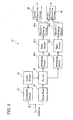
- FIG. 9 is a block diagram showing the configuration of the second radar 47.
- the second radar 47 is provided with a transmitting and receiving antenna 74 for transmitting and receiving radio waves.
- An oscillation circuit 72 is connected with the transmitting and receiving antenna 74 (specifically, with a radio wave transmitting member of the transmitting and receiving antenna 74), and a clock circuit 70 is connected with the oscillation circuit 72.
- the clock circuit 70 periodically transfers the frequency of the voltage that is output from the oscillation circuit 72 to two-phase, and simultaneously switches the state of a switch 78. As a result, as shown in FIG.
- a diode mixer 76 is connected with the transmitting and receiving antenna 74 (specifically, with the radio wave receiving member of the transmitting and receiving antenna 74).
- the receiving antenna 74 receives (1) the radio waves that have been transmitted from the transmitting antenna 74 and that have not been reflected and (2) the radio waves that have been reflected from the reflector.
- the diode mixer 76 multiplies the radio waves of (1) and (2) and outputs detected wave voltages (a so-called waveform detecting circuit).
- the output voltage from the diode mixer 76 varies on the basis of whether or not the reflector is moving towards the second radar 47 (in other words, in the direction in which work is sent).
- the radio waves reflected by the reflector have the same frequency as the radio waves transmitted from the transmitting and receiving antenna 74.
- the radio waves reflected by the reflector have a frequency different from that of the radio waves transmitted by the transmitting and receiving antenna 74 if the reflector is moving.
- the second radar 47 is a radar that measures the speed of movement of the reflector utilizing the frequency of these beats.
- the output voltage of the diode mixer 76 also differs from the frequency of the radio waves output from the transmitting and receiving antenna 74.
- the second radar 47 is a radar that transmits radio waves having mutually differing frequencies, detects the beats generated by these differing frequencies of radio wave, and measures the position of the reflector (the distance from the second radar 47) from the phase difference of the beats.
- the first circuit group consists of an amplifying circuit 80a, a filter circuit 82a and a waveform shaping circuit 84a.
- the second circuit group consists of an amplifying circuit 80b, a filter circuit 82b, and a waveform shaping circuit 84b.
- the first circuit group is connected with the diode mixer 76 when the transmitting and receiving antenna 74 is transmitting radio waves at the first frequency.
- the second circuit group is connected with the diode mixer 76 when the transmitting and receiving antenna 74 is transmitting radio waves at the second frequency.
- the structure and effects of the circuits is identical with those of the circuits used in the first radar 46.
- the second radar 47 is provided with a speed measuring circuit 86 and a phase difference measuring circuit 88.
- the speed measuring circuit 86 is connected with the waveform shaping circuit 84a, and the output voltage of the waveform shaping circuit 84a is input to the speed measuring circuit 86.
- the speed measuring circuit 86 measures the frequency of the beats generated in the output voltage of the waveform shaping circuit 84a (in other words, it measures the speed of the reflector).
- the phase difference measuring circuit 88 is connected with both the waveform shaping circuits 84a and 84b, and the output voltage of both the waveform shaping circuits 84a and 84b are input to the phase difference measuring circuit 88.
- the phase difference measuring circuit 88 is a circuit that measures the phase difference between the output voltages of the waveform shaping circuits 84a and 84b (in other words, it measures the position of the reflector).
- the measurement results of the speed measuring circuit 86 and of the phase difference measuring circuit 88 are both input to the controlling member 15.
- the radio waves utilized by the second radar 47 are 1 to 30 GHz. In the present embodiment, 24.2 GHz microwaves are used. Since it is preferred that the second radar 47 monitors only the surroundings of the circular saw 3, radio waves are used that have a higher frequency than that of the first radar 46 and the directivity of the radio waves is thus increased. Further, the wavelength grows shorter as the frequency of radio waves is made higher. This allows the location and speed of the reflector to be measured accurately. Moreover, the antenna shape and location of the second radar 47 are determined so that a desired directivity (that is, a directivity adequate to monitor the surroundings of the circular saw 3) can be obtained when radio waves at the above frequencies are transmitted.
- a desired directivity that is, a directivity adequate to monitor the surroundings of the circular saw 3
- the present applicant has created power tools wherein the surroundings thereof are monitored by radar, and has applied for patents thereof ( Japanese Patent Application 2002-328837 , Japanese Patent Application 2003-81399 ).
- a technique is set forth for monitoring the surroundings of a power tool by means of radar in Japanese Patent Application 2002-328837 .
- a technique utilizing a microstrip antenna or a patch antenna in a power tool is set forth in Japanese Patent Application 2003-81399 . These techniques can be effectively utilized in the table saw 1.
- the electrical configuration of the table saw 1 is shown in FIG. 11.
- the controlling member 15 is provided with a microcomputer 91.
- the microcomputer 91 is provided with a CPU, ROM, RAM and I/0.
- a program for controlling the table saw 1 is stored in the ROM of the microcomputer 91.
- the controlling member 15 is provided with a solenoid controller 97, a motor controller 99, and a regenerative braking circuit 100.
- the solenoid controller 97, the motor controller 99, and the regenerative braking circuit 100 are connected with the microcomputer 91.
- the solenoid 38 is connected with the solenoid controller 97.
- the solenoid controller 97 operates the solenoid 38.
- the microcomputer 91 gives operating commands for the solenoid 38.
- the motor 11 is connected with the motor controller 99.
- the motor controller 99 controls the driving operation of the motor 11.
- the microcomputer 91 gives driving commands for the motor 11.
- the motor 11 is connected with the regenerative braking circuit 100.
- the regenerative braking circuit 100 closes the circuit to the motor 11 and causes the motor 11 to generate power. By causing the motor 11 to generate power, the regenerative braking circuit 100 reduces the inertial energy of the motor 11 and thus brakes the motor 11.
- the microcomputer 91 gives operating commands for the regenerative braking circuit 100.
- a warning device 102 and a driving switch 55 are connected with the microcomputer 91.
- the warning device 102 is capable of sounding a first warning and a second warning. The first warning and the second warning generate mutually differing alarm sounds.
- the warning device 102 sounds the first warning or the second warning on the basis of commands from the microcomputer 91.
- the table saw 1 is provided with a power supply circuit 101. Power is supplied to each component via the power supply circuit 101.
- the first radar 46 and the second radar 47 are connected with the microcomputer 91.
- the microcomputer 91 detects the received waveforms that are input from the first radar 46, detects the peak 'a' and the peak 'c' shown in FIG. 8, and calculates the period t1 - t0 between these peaks.
- the distance between the circular saw 3 and the reflector is found from this calculated period. It is determined whether the reflector is in the first prescribed area from the distance that has thus been found.
- the frequency of the beats measured by the speed measuring circuit 86, and the phase difference of the beats measured by the phase difference measuring circuit 88 are input from the second radar 47.
- the microcomputer 91 calculates the speed at which the reflector is approaching the circular saw 3 from the frequency of the beats that were input, and calculates the distance between the circular saw 3 and the reflector from the phase difference of the beats that were input.
- a condition-determining map 110 shown in FIG. 12, is stored in the ROM of the microcomputer 91.
- the condition-determining map 110 is a two-dimensional map wherein the distance to the circular saw 3 is shown on the vertical axis, and the speed of approach to the circular saw 3 is shown on the horizontal axis.
- the condition-determining map 110 is divided based on the ratios of risk as to whether an object other than work W will make contact with the circular saw 3.
- the ratios of risk are classified based on pairs of values relating to the distance to the circular saw 3 and the speed of approach to the circular saw 3.
- the condition-determining map 110 has a normal region 111, an abnormal region 112, and a risk region 113. In FIG. 12, the boundary of each region is shown by a solid line.
- the broken lines do not indicate boundaries.
- the normal region 111 is a region showing pairs of values detected during normal processing operations.
- the abnormal region 112 and the risk region 113 are regions showing pairs of values that are not detected during normal processing operations.
- the risk region 113 has a greater proportion of abnormality than the abnormal region 112. These have a higher risk that an object other than work W will make contact with the circular saw 3.
- the abnormal region 112 and the risk region 113 are determined on the basis of the time remaining before the detected object makes contact with the circular saw 3. This remaining time is found from the distance from the circular saw 3 and the speed of approach to the circular saw 3 that have been detected.
- the abnormal region 112 is a region wherein the remaining time is shorter than T1.
- the risk region 113 is a region wherein the remaining time is shorter than T2.
- the period T2 is shorter than the period T1.
- the slope of the broken line 116 shows T1.
- the slope of the broken line 117 shows T2.
- the region below the broken line 116 is a region in which the remaining time is less than T1. This is the abnormal region 112.
- the region below the broken line 117 is a region in which the remaining time is less than T2. This is the risk region 113.
- a region wherein a distance to the circular saw 3 is equal to or less than d1 is also set to be within the abnormal region 112 although it is within the region in which the remaining time is longer than T1. Further, a region in which a distance to the circular saw 3 is equal to or less than d2 is set so as to be within the risk region 113.
- the distance d2 is shorter than the distance d1.
- the distance d1 is a distance wherein an object other than work W must not, for safety reasons, approach the circular saw 3 during normal processing operations of the table saw 1. Consequently, an abnormal state is determined irrespective of the speed of the object when an object other than work W has approached the circular saw 3 within the distance d1.
- a state of risk is determined irrespective of the speed of the object when an object other than work W has approached the circular saw 3 within the distance d2.
- a region wherein the speed of approach to the circular saw 3 is equal to or greater than v1 is set to form the abnormal region 112 although the region, determined from the remaining time, should have been within the normal region 111.
- the speed of approach v1 is a speed at which it is estimated that an object other than work W will not approach the circular saw 3 during normal processing operations of the table saw 1.
- a boundary 114 is formed between the normal region 111 and the abnormal region 112 in the condition-determining map 110. Further, a boundary 115 is formed between the abnormal region 112 and the risk region 113.
- the boundary 114 functions as a first criterion for determining the risk that an object other than work W will make contact with the circular saw 3.
- the boundary 115 functions as a second criterion for determining the risk that an object other than work W will make contact with the circular saw 3.
- the first criterion and the second criterion with the exception of an area that is extremely close to the circular saw 3 - distance from the circular saw 3 is set to become greater as speed increases. Further, relative to the same speed, this distance is longer in the first criterion than in the second criterion.
- the greatest value on the vertical axis is the distance D
- the greatest value on the horizontal axis is the speed v2.
- the distance D is the distance that is furthest from the circular saw 3 of the regions monitored by the first radar 46 and the second radar 47.
- the speed v2 is the greatest speed at which it is estimated an object other than work W will approach the circular saw 3.
- the speed v2 is set using normal usage of the table saw 1 as a reference.
- the microcomputer 91 determines the condition-determining map 110 using the pairs of values of the distance of the reflector from the circular saw 3 and the speed of approach to the circular saw 3 that were detected by the first radar 46 and the second radar 47. By this means, it is possible to determine whether there is a risk that the reflector that has been detected will make contact with the circular saw 3. Should this risk be present, the likelihood of this risk can be determined.
- the sequence of operations of the table saw 1 will now be described using the flowchart of FIG. 13.
- the starting point of the flowchart 13 is the insertion of a power supply switch (not shown) of the table saw 1.
- the table saw 1 is in a waiting state until the operator turns the driving switch 55 ON.
- the driving switch 55 has been turned ON, the process proceeds to step S3.
- the first radar 46 and the second radar 47 begin to operate.
- the microcomputer 91 controls the output voltages of the first radar 46 and the second radar 47 and begins to monitor for reflectors (objects other than work W).
- the microcomputer 91 determines whether a reflector is in the monitored areas (the first prescribed area A and the second prescribed area B).
- step S7 When the presence of a reflector (an object other than work W) is not detected in the monitored areas, the process proceeds to step S7.
- the waveforms received from the first radar 46 immediately after the insertion of the driving switch 55 may be stored in the RAM of the microcomputer 91. These stored waveforms are preliminary period waveforms, and can be utilized for noise processing during subsequent processing of the received waveforms. By this means, the reflected waves of the circular saw 3, etc. can be eliminated from the received waveforms and an object other than work W can thereby be detected accurately.
- step S31 the warning device 102 sounds the second warning, and the operation of the table saw 1 is halted.
- the microcomputer 91 commands the motor controller 99 to drive the motor 11.
- the rotational power of the motor 11 is transmitted to the saw shaft 27 via the one-way clutch 29.
- the circular saw 3 rotates together with the saw shaft 27.
- the first prescribed area A is the area chiefly monitored by the first radar 46. If the presence of a reflector is detected (YES), the process proceeds to step S11. If the presence of a reflector is not detected (NO), the process proceeds to step S21.
- the first prescribed area A is an area in which, for safety reasons, an object other than work W must not be present during normal processing operations.
- the microcomputer 91 gives operating commands to the regenerative braking circuit 100 and the regenerative braking of the motor I 1 occurs.
- the motor 11 is braked, the rotation speed of the gear 21 decreases.
- the one-way clutch 29 causes the gear 21 and the saw shaft 27 to disengage.
- the circular saw 3 and the saw shaft 27 are thus both in a state of inertial rotation.
- the warning device 102 sounds the first warning. By this means, the operator can be informed that there is the risk of an object other than work W making contact with the circular saw 3.
- step S13 of FIG. 13 it is determined whether the reflector has retreated from the first prescribed area A. If the presence of the reflector in the first prescribed area A is not detected (YES), the process proceeds to step S19. If the continuing presence of the reflector in the first prescribed area A is detected (NO), the process proceeds to step S 15. At step S15, the period for which the reflector is remaining in the first prescribed area A is compared with a prescribed period. When the period for which the detected reflector has remained in the first prescribed area A exceeds the prescribed period (YES), the process proceeds to step S 17. In the case where the period that the detected reflector has remained in the first prescribed area A does not exceed the determined period (NO), the process returns to step S13. At step S17, the saw shaft brake 31 operates.
- the microcomputer 91 commands solenoid controller 97 to operate the solenoid 38.
- Operating the solenoid 38 activates the saw shaft brake 31.
- the saw shaft brake 31 forcibly brakes the saw shaft 27, thus halting the saw shaft 27. That is, the rotation of the circular saw 3 is halted.
- the rotation of the circular saw 3 is halted at the point at which it is detected that there is a risk that an object other than work W will make contact with the circular saw 3.
- the saw shaft brake 31 When the saw shaft brake 31 is operating, the rotation speed at the motor 11 side is reduced and the one-way clutch rotates idly. Consequently, the saw shaft brake 31 needs to brake only the components at the rotating tool side (the circular saw 3, the saw shaft 27, etc.).
- step S17 the warning device 102 sounds the second warning, thus informing the operator that the saw shaft brake 31 is operating.
- the operation of the table saw 1 halts.
- step S13 is YES
- step S19 the regenerative braking of the motor 11 is halted at step S19
- the first warning is halted.
- step S21 the process then proceeds to step S21.
- the above sequence is a state wherein the object other than work W temporarily approached the tool and then retreated. For example, the operator may have inadvertently allowed a finger to approach the circular saw 3 and became aware of the risk upon hearing the first warning.
- the regenerative braking of the motor 11 is halted and it is possible to continue operations using the table saw 1.
- step S21 of FIG. 13 it is determined whether the reflector (the object other than work W) is present in the second prescribed area B.
- the second prescribed area B is the area chiefly monitored by the second radar 47.
- the process proceeds to step S23.
- the presence of a reflector is not detected (NO)
- the process returns to step S9.
- the pairs of values relating to the distance to the circular saw 3 of the detected reflector and the speed of approach to the circular saw 3 of the detected reflector are determined using the condition-determining map 110.
- the pairs of values that have been detected are in the abnormal region 112 (YES)
- the process proceeds to step S25.
- step S25 the regenerative braking of the motor 11 is caused and the warning device 102 sounds the first warning. This is identical with step S 11.
- step S27 as with step S23, the degree of risk that the reflector will make contact with the circular saw 3 is determined from the pairs of values relating to the detected distance to the circular saw 3 of the reflector and the detected speed of approach to the circular saw 3 of the reflector.
- the microcomputer 91 compares the detected pairs of values with the condition-determining map 110. When the pairs of values that have been detected are in the risk region 113 of the condition-determining map 110 (YES), the process proceeds to step S29. When the pairs of values that have been detected are not in the risk region 113 of the condition-determining map 110 (NO), to step S33.
- step S29 the saw shaft brake 31 operates. This is identical with step S17. That is, the rotation of the circular saw 3 is halted. The rotation of the circular saw 3 is halted at the point at which it is detected that there is a high risk of an object other than work W making contact with the circular saw 3. Following this, at step S31, the warning device 102 sounds the second warning. The operation of the table saw 1 is halted.
- step S27 determines whether the pairs of values belong in the normal region 111 of the condition-determining map 110.
- the process proceeds to step S35.
- step S35 the regenerative braking of the motor 11 is halted, and the first warning is halted.
- the process then returns to step S9.
- the above sequence is a state wherein an object other than work W temporarily approached the tool and then retreated. For example, the operator inadvertently allowed a finger to approach the circular saw 3 and became aware of the risk upon hearing the first warning.
- step S33 the process returns to step S15. This case shows that the abnormal state is continuing, the regenerative braking of the motor 11 is continued, and the reflector continues to be monitored.
- the table saw 1 is monitored by two radars: the first radar 46 and the second radar 47.
- the first radar 46 mainly monitors the first prescribed area A that is in the vicinity of the processing location of the circular saw 3.
- the first prescribed area A is an area in which an object other than work W must not be present.
- the first radar 46 When an object other than work W enters the first prescribed area A this is promptly detected by the first radar 46, and regenerative braking of the motor 11 is performed. Further, the first warning is sounded.
- the saw shaft brake 31 operates and the circular saw 3 is halted.
- the regenerative braking is a braking in a comparatively gentle manner, and consequently a low load is exerted on the table saw 1.
- the saw shaft brake 31 performs rapid braking by exerting a strong braking force.
- speed has already been reduced by the regenerative braking of the motor 11. Consequently no particularly heavy load is exerted on the saw shaft brake 31, and no particularly strong counter force is exerted on the table saw 1 or on the support of the table saw 1.
- the second radar 47 mainly monitors the second prescribed area B.
- the second prescribed area B is an area in which an object other than work W can be present during normal operation. Consequently, it is not possible to determine the degree of risk using merely the presence or absence of a reflector.
- the second radar 47 detects both the distance of the reflector to the circular saw 3 and the speed of approach of the reflector to the circular saw 3. By this means, in the table saw 1, it is possible to detect the degree of risk as to whether the detected reflector will make contact with the circular saw 3, and to brake the circular saw 3 based on this degree of risk.
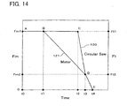
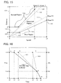
- FIG. 14 shows changes over time in the rotation speed of the circular saw 3 and the motor 11 (number of rotations/unit of time) while the circular saw 3 is being braked on the basis of the results detected by the second radar 47.
- the rotation speed Ft of the circular saw 3 is on the right vertical axis
- the rotation speed Fm of the motor 11 is on the left vertical axis.
- the scale of the left and right vertical axes is magnified with respect to the rate of speed of the motor 11 and the circular saw 3. This allows the relationship between the rotation speed Ft of the circular saw 3 and the rotation speed Fm of the motor 11 to be compared easily.
- the overlapping of the rotation speed of the circular saw 3 and the motor 11 indicates that the circular saw 3 and the motor 11 are rotating in unison.
- FIG. 14 shows a case in which the table saw 1, which is being driven at rated output, has regenerative braking applied to the motor 11 at time t1 (step S25), and in which the saw shaft brake 31 is operated at time t2 (step S29).
- the rotation speed of the circular saw 3 is Ft1
- the rotation speed of the motor 11 is Fm1.
- the changes over time in the rotation speed of the circular saw 3 are shown by the solid line 120 that joins the points A, B, C, D, and E.
- the changes over time in the rotation speed of the motor 11 are shown by the solid line 121 that joins the points A, B, D, and E.
- the regenerative braking of the motor 11 begins, and the rotation speed of the motor 11 decreases (line segment BD).
- This emergency braking is gentle, and no particularly strong counter force is exerted on the motor 11 or on the support thereof.
- the one-way clutch 29 causes the circular saw 3 and the motor 11 to be in a disengaged state.
- the circular saw 3 continues to rotate at approximately the same speed due to inertia.
- the saw shaft brake 31 operates, whereupon the rotation speed of the circular saw 3 falls rapidly.
- the saw shaft brake 31 brakes only the components at the rotating tool side (the circular saw 3, the saw shaft 27, etc.).
- the saw shaft brake 31 can rapidly reduce the rotation speed of the circular saw 3. Further, the load exerted on the saw shaft brake 31 at this juncture is also reduced.
- the regenerative braking of the motor 11 and the saw shaft brake 31 both operate.
- the greatest load is exerted on the saw shaft brake 31 at the times t2 and t3.
- greatest load is exerted at the time t2 when braking of the circular saw 3 that is rotating due to inertia at approximately the rated rotation speed Ft1 begins, and at the time t3 when the one-way clutch 29 causes the circular saw 3 and the motor 11 to be connected again.
- the saw shaft brake 31 can thus be configured so as to be able to withstand the load of these two times t2 and t3.
- the saw shaft brake 31 can be utilized efficiently by designing so that an identical load is exerted on the saw shaft brake 31 at these two times t2 and t3.
- the load exerted on the saw shaft brake 31 at time t3 is determined, more or less, by the rotation speed of the motor 11 at that time.
- the rotation speed of the motor 11 at time t3 varies in accordance with the time at which regenerative braking of the motor 11 begins (time t1). That is, the braking capacity of the regenerative braking circuit 100 and the capacity of the saw shaft brake 31 have a close connection with the time at which regenerative braking of the motor 11 begins and the time at which the saw shaft brake 31 is operated.
- condition-determining map 110 allow the capacity of the regenerative braking circuit 100 and of the saw shaft brake 31 to be effectively utilized. This improves the likelihood that the circular saw 3 will reliably halt operation before the object other than work W makes contact therewith.
- the second prescribed area is monitored by the second radar 47.
- the radio waves utilized by the second radar 47 penetrate the work W and are reflected from the object other than work W. That is, only the object other than work W is an effective reflector.
- the radar it is possible to recognize the object other than work W and to detect the likelihood of this object making contact with the rotating circular saw 3.
- the regenerative braking of the motor 11 and the saw shaft brake 31 are operated based on the degree of likelihood of the object making contact with the rotating circular saw 3.
- the period required for braking the circular saw 3 is ensured.
- the rotation of the circular saw 3 can be halted before the object other than the work W makes contact therewith.
- the regenerative braking circuit 100 and the saw shaft brake 31 have a compact and simple configuration, and can easily return to their original state after an emergency stop.
- contact between the rotating circular saw 3 and an object other than work W can be, as far as possible, prevented.
- the table saw 1 is provided with the safety cover 7. Using this safety cover 7 allows the safety of the user etc. to be further ensured.
- two radars are utilized: the first radar 46 and second radar 47. Each of these radars independently performs monitoring. Consequently, should one of the radars fail, the remaining radar can continue monitoring.
- EMBODIMENT 2 A table saw of Embodiment 2 that utilizes the technique of the present teachings is substantially identical with Embodiment 1, with only portions thereof being modified. Consequently, the description will focus on the parts differing from the table saw 1 of Embodiment 1. The points wherein the table saw of Embodiment 2 differs from the table saw 1 of Embodiment 1 will first be listed.
- the second condition-determining map 130 used in Embodiment 2 will now be described.
- the second condition-determining map 130 shown in FIG. 15 has been modified, relative to the condition-determining map 110 of Embodiment 1, to have a boundary 128 (a first criterion) between a normal region 131 and an abnormal region 132. Specifically, a portion of the boundary 128 (the first criterion) is further upwards, relative to the figure, than its equivalent in the condition-determining map 110 of Embodiment 1 (the broken line 116 shown in FIG.
- a portion of the boundary 129 (the second criterion) is further downwards, relative to the figure, than its equivalent in the condition-determining map 110 of Embodiment 1 (the broken line 117 shown in FIG. 15), and this portion is located on a broken line 127.
- the slope of the broken line 127 shows T4.
- the saw shaft brake 31 is operated when the remaining time (the time until the object other than work that has been detected makes contact with the circular saw 3) is equal to or below T4.
- the time T4 is shorter than the remaining time T2 of Embodiment 1. That is, when an object other than work is approaching the circular saw 3, the shaft brake 31 will be operated at a later time with the table saw of Embodiment 2 than with the table saw 1 of Embodiment 1.
- FIG. 16 shows changes over time in the rotation speed of the circular saw 3 and the motor 11 (number of rotations/unit of time) when the circular saw 3 is braked. These changes over time are required for halting the rotation of the circular saw 3 before the time t4.
- the time t4 is equal to the time t4 shown in FIG. 14 which is earlier than a time when the object makes contact with the circular saw 3.
- the saw shaft brake 31 operates.
- the rotation speed of the circular saw 3 is Ft2 and the rotation speed of the motor 11 is Fm2. That is, the same conditions as with the table saw 1 of Embodiment 1 are obtained at time t3.
- the circular saw 3 is completely halted at time t4.
- the load exerted on the saw shaft brake 31 does not exceed that of Embodiment 1, and there is no damage to the saw shaft brake 31, etc.
- the table saw of Embodiment 2 it is possible in the table saw of Embodiment 2 to stop the circular saw 3 before the time at which the object other than work makes contact with the rotating circular saw 3. That is, contact between the circular saw 3 under rotation and an object other than work W can be, as far as possible, prevented. Since the table saw of Embodiment 2 does not have the one-way clutch, the configuration thereof is simpler.
- EMBODIMENT 3 A table saw of Embodiment 3 for practicing the present teachings is a variant of the table saw 1 of Embodiment 1. Consequently, the description will focus on the parts differing from the table saw 1 of Embodiment 1. The points wherein the table saw of Embodiment 3 differs from the table saw 1 of Embodiment 1 will first be listed.
- a boundary 138 (a first criterion) between a normal region 141 and an abnormal region 142.
- a portion of the boundary 138 (the first criterion) is downward, relative to the figure, than its equivalent in the condition-determining map 110 of Embodiment 1 (the broken line 116 shown in FIG. 17), and this portion is located on a broken line 136.
- the slope of the broken line 136 shows T5.
- the clutch causes the gear 21 and the saw shaft 27 to be in a state wherein power is not transmitted.
- the remaining time T5 is shorter than the remaining time T1 of Embodiment 1. That is, when an object other than work is approaching the circular saw 3, regenerative braking of the motor 11 is performed at a later time with the table saw of Embodiment 3 than with the table saw 1 of Embodiment 1. Further, the clutch simultaneously causes the gear 21 and the saw shaft 27 to be in a state wherein power is not transmitted. Furthermore, a boundary 139 (a second criterion) between the abnormal region 142 and a risk region 143 has been modified.
- a portion of the boundary 139 (the second criterion) is downward, relative to the figure, than its equivalent in the condition-determining map 110 of Embodiment 1 (the broken line 117 shown in FIG. 17), and this portion is located on a broken line 137.
- the slope of the broken line 137 shows T6.
- the saw shaft brake 31 is operated when the remaining time (the time until the object other than work that has been detected makes contact with the circular saw 3) is equal to or less than T6.
- the time T6 is shorter than the remaining time T2 of Embodiment 1. That is, when an object other than work is approaching the circular saw 3, the shaft brake 31 is operated at a later time with the table saw of Embodiment 3 than with the table saw 1 of Embodiment 1.
- FIG. 18, like FIG. 14, shows changes over time in the rotation speed of the circular saw 3 and the motor 11 (number of rotations/unit of time) when the circular saw 3 is braked. These changes over time are required for halting the rotation of the circular saw 3 before the time t4.
- the time t4 is equal to the time t4 shown in FIG. 14 which is earlier than a time when the object makes contact with the circular saw 3.
- regenerative braking of the motor 11 occurs at time t2', and the clutch simultaneously causes the gear 21 and the saw shaft 27 to be in a state wherein power is not transmitted.
- the saw shaft brake 31 is operated at time t3', and the rotation of the circular saw 3 is halted by time t4.
- the changes over time in the rotation speed of the circular saw 3 are shown by the solid line 144 that joins the points A, H, and E.
- the changes over time in the rotation speed of the motor 11 are shown by the solid line 145 that joins the points A, G, and J.
- the clutch causes the gear 21 and the saw shaft 27 to be in a disengaged state.
- the circular saw 3 continues to rotate at approximately the same speed due to inertia.
- the friction between the circular saw 3 and the work W brakes the circular saw 3, and the rotation speed of the circular saw 3 falls.
- the saw shaft brake 31 operates.
- the circular saw 3 is not in an engaged state with the motor 11, which has a large moment of inertia. Consequently, the rotation speed of the circular saw 3 falls rapidly.
- the speed of the circular saw 3 can be reduced without this having any connection with the speed of the motor 11.
- the circular saw 3 is braked rapidly, and is completely halted at time t4. That is, it is not necessary to halt the motor 11 with the table saw of Embodiment 3.
- the regenerative braking circuit 100 can also, for example, be omitted.
- the clutch of the table saw of Embodiment 3 can be, for example, an electromagnetic power clutch, a pneumatic clutch, etc. Furthermore, a centrifugal clutch can also be utilized as an additional brake for braking the motor 11.
- the centrifugal clutch transmits power to the saw shaft 27 when the motor 11 is rotating above a determined number of rotations, and does not transmit power to the saw shaft 27 when the motor 11 is rotating below a determined number of rotations.
- the motor 11 that is rotating at a rated rotation is braked, the rotation speed of the motor 11 falls, and the gear 21 and the saw shaft 27 assume a disengaged state. That is, the driving operation of the motor 11 switches the gear 21 and the saw shaft 27 between an engaged state and a disengaged state when braking is controlled.
- the table saw of this aspect can be realized by replacing the one-way clutch 29 with the centrifugal clutch in the table saw 1 of Embodiment 1.
- the saw brake may be a brake as shown in FIG. 19.
- the saw brake shown in FIG: 19 has a configuration wherein a needle 34a is caused to protrude when power passes through a solenoid 34, and thereupon the sliding block 33 makes contact with the expanded diameter member 28.
- a needle 34a is caused to protrude when power passes through a solenoid 34, and thereupon the sliding block 33 makes contact with the expanded diameter member 28.
Landscapes
- Engineering & Computer Science (AREA)
- Mechanical Engineering (AREA)
- Life Sciences & Earth Sciences (AREA)
- Wood Science & Technology (AREA)
- Forests & Forestry (AREA)
- General Engineering & Computer Science (AREA)
- Radar, Positioning & Navigation (AREA)
- Remote Sensing (AREA)
- Sawing (AREA)
- Radar Systems Or Details Thereof (AREA)
Claims (9)
- Kraftwerkzeug (1) mit einem rotierenden Werkzeug (3) und einem Motor (11) zum Drehen des rotierenden Werkzeugs, und
einem Radar (47) zum Senden von Funkwellen in Richtung eines Bereiches (B) in der Nähe des rotierenden Werkzeugs und zum Empfangen von Funkwellen (c), die von einem innerhalb des Bereiches existierenden Funkwellenreflektor reflektiert werden,
dadurch gekennzeichnet, dass das Kraftwerkzeug ferner aufweist
ein Mittel (86, 88, 91) zum Berechnen eines Abstands zwischen dem Funkwellenreflektor und dem rotierenden Werkzeug (3) und einer Geschwindigkeit der Veränderung des Abstands aus den vom Radar empfangenen, reflektierten Funkwellen,
eine erste Bremse (100) zum Ausüben einer leichten Bremswirkung auf den Motor (11), das rotierende Werkzeug oder ein mit dem rotierenden Werkzeug verbundenes Bauteil (28), wenn der berechnete Abstand und die berechnete Geschwindigkeit ein erstes Kriterium erfüllen, und eine zweite Bremse (31) zum Ausüben einer schnellen Bremswirkung auf das rotierende Werkzeug oder ein mit dem rotierenden Werkzeug verbundenes Bauteil, wenn der berechnete Abstand und die berechnete Geschwindigkeit ein zweites Kriterium erfüllen. - Kraftwerkzeug (1) nach Anspruch 1, bei dem der Abstand im ersten Kriterium und im zweiten Kriterium mit zunehmender Geschwindigkeit zunimmt, und der Abstand, der einer bestimmten Geschwindigkeit im ersten Kriterium entspricht, länger ist als der Abstand, der der gleichen Geschwindigkeit im zweiten Kriterium entspricht.
- Kraftwerkzeug (1) nach Anspruch 1 oder 2, das weiter aufweist
eine zwischen dem rotierenden Werkzeug (3) und dem Motor (11) eingefügte Einwegkupplung (29), wobei die Einwegkupplung das rotierende Werkzeug und den Motor in einen entkuppelten Zustand bringt, falls die Drehgeschwindigkeit auf der Motorseite langsamer ist als die Drehgeschwindigkeit auf der Seite des rotierenden Werkzeugs,
bei dem die erste Bremse (100) die Bremskraft auf ein Bauteil (11) auf der Motorseite der Einwegkupplung ausübt und die zweite Bremse (31) die Bremskraft auf ein Bauteil (28) auf der Seite des rotierenden Werkzeugs der Einwegkupplung ausübt. - Kraftwerkzeug nach Anspruch 1 oder 2, das weiter aufweist
eine zwischen dem rotierenden Werkzeug (3) und dem Motor (11) eingefügte Kupplung, die geeignet ist zum Schalten des rotierenden Werkzeugs und des Motors zwischen einem gekuppelten Zustand und einem entkuppelten Zustand,
bei dem die erste Bremse durch Schalten der Kupplung im entkuppelten Zustand einen Zustand veranlasst, in dem die Bremskraft, die auf das rotierende Werkzeug ausgeübt wird, mittels zwischen dem rotierenden Werkzeug und einem Werk (W) erzeugten Reibung, und die zweite Bremse (31) die Bremskraft auf ein Bauteil (28) an der Seite des rotierenden Werkzeugs der Einwegkupplung ausübt. - Kraftwerkzeug (1) nach einem der Ansprüche 1 bis 4, bei dem die erste Bremse (100) eine regenerative Bremse zum Bremsen eines Elektromotors (11) durch Bringen des Elektromotors zur Erzeugung von Leistung ist.
- Kraftwerkzeug (1) nach einem der Ansprüche 1 bis 5, bei dem die vom Radar benutzte Frequenz der Funkwellen innerhalb des Bereiches von 1 bis 30 GHz liegt.
- Kraftwerkzeug (1) aufweisend:einen Motor (11) zum Bringen eines Werkzeugs (3) zum Rotieren,ein Radar (47) zum Senden von Funkwellen in Richtung eines Bereiches (B) in der Nähe des rotierenden Werkzeugs und zum Empfangen von Funkwellen, die von einem innerhalb des Bereiches existierenden Funkwellenreflektor reflektiert werden,dadurch gekennzeichnet, dass das Kraftwerkzeug weiter aufweisteine zwischen dem rotierenden Werkzeug und dem Motor eingefügte Kupplung (29), die geeignet ist zum Schalten des rotierenden Werkzeugs und des Motors zwischen einem gekuppelten Zustand und einem entkuppelten Zustand,ein Mittel (86, 88, 91) zum Berechnen eines Abstands zwischen dem Funkwellenreflektor und dem rotierenden Werkzeug (3) und einer Geschwindigkeit der Veränderung des Abstands aus den vom Radar empfangenen, reflektierten Funkwellen,ein Mittel (91, 100; 100) zum Schalten der Kupplung in den entkuppelten Zustand, wenn der berechnete Abstand und die berechnete Geschwindigkeit ein erstes Kriterium erfüllen, undeine Werkzeugbremse (31) zum Ausüben einer Bremswirkung auf das rotierende Werkzeug, wenn der berechnete Abstand und die berechnete Geschwindigkeit ein zweites Kriterium erfüllen.
- Kraftwerkzeug (1) nach Anspruch 7, bei dem der Abstand im ersten Kriterium und im zweiten Kriterium mit zunehmender Geschwindigkeit zunimmt, und der Abstand, der einer bestimmten Geschwindigkeit im ersten Kriterium entspricht, länger ist als der Abstand, der der gleichen Geschwindigkeit im zweiten Kriterium entspricht.
- Kraftwerkzeug (1) nach Anspruch 7 oder 8, bei dem die Kupplung eine elektromagnetische Kupplung, eine pneumatische Kupplung oder eine Zentrifugalkupplung ist.
Applications Claiming Priority (2)
| Application Number | Priority Date | Filing Date | Title |
|---|---|---|---|
| JP2003322022A JP2005088248A (ja) | 2003-09-12 | 2003-09-12 | 動力工具 |
| JP2003322022 | 2003-09-12 |
Publications (3)
| Publication Number | Publication Date |
|---|---|
| EP1514656A1 EP1514656A1 (de) | 2005-03-16 |
| EP1514656B1 EP1514656B1 (de) | 2007-03-07 |
| EP1514656B9 true EP1514656B9 (de) | 2007-08-01 |
Family
ID=34132068
Family Applications (1)
| Application Number | Title | Priority Date | Filing Date |
|---|---|---|---|
| EP04020453A Expired - Lifetime EP1514656B9 (de) | 2003-09-12 | 2004-08-27 | Kraftwerkzeug |
Country Status (4)
| Country | Link |
|---|---|
| US (1) | US7084779B2 (de) |
| EP (1) | EP1514656B9 (de) |
| JP (1) | JP2005088248A (de) |
| DE (1) | DE602004005115T2 (de) |
Families Citing this family (71)
| Publication number | Priority date | Publication date | Assignee | Title |
|---|---|---|---|---|
| US20020017179A1 (en) * | 2000-08-14 | 2002-02-14 | Gass Stephen F. | Miter saw with improved safety system |
| US7210383B2 (en) | 2000-08-14 | 2007-05-01 | Sd3, Llc | Detection system for power equipment |
| US7353737B2 (en) | 2001-08-13 | 2008-04-08 | Sd3, Llc | Miter saw with improved safety system |
| US7290472B2 (en) | 2002-01-14 | 2007-11-06 | Sd3, Llc | Miter saw with improved safety system |
| US7100483B2 (en) | 2000-08-14 | 2006-09-05 | Sd3, Llc | Firing subsystem for use in a fast-acting safety system |
| US7308843B2 (en) * | 2000-08-14 | 2007-12-18 | Sd3, Llc | Spring-biased brake mechanism for power equipment |
| US8061245B2 (en) | 2000-09-29 | 2011-11-22 | Sd3, Llc | Safety methods for use in power equipment |
| US6994004B2 (en) | 2000-09-29 | 2006-02-07 | Sd3, Llc | Table saw with improved safety system |
| US7024975B2 (en) | 2000-08-14 | 2006-04-11 | Sd3, Llc | Brake mechanism for power equipment |
| US7171879B2 (en) | 2001-07-02 | 2007-02-06 | Sd3, Llc | Discrete proximity detection system |
| US7509899B2 (en) | 2000-08-14 | 2009-03-31 | Sd3, Llc | Retraction system for use in power equipment |
| US9724840B2 (en) | 1999-10-01 | 2017-08-08 | Sd3, Llc | Safety systems for power equipment |
| US7137326B2 (en) | 2000-08-14 | 2006-11-21 | Sd3, Llc | Translation stop for use in power equipment |
| US20030131703A1 (en) | 2002-01-16 | 2003-07-17 | Gass Stephen F. | Apparatus and method for detecting dangerous conditions in power equipment |
| US7055417B1 (en) | 1999-10-01 | 2006-06-06 | Sd3, Llc | Safety system for power equipment |
| US7712403B2 (en) | 2001-07-03 | 2010-05-11 | Sd3, Llc | Actuators for use in fast-acting safety systems |
| US7077039B2 (en) | 2001-11-13 | 2006-07-18 | Sd3, Llc | Detection system for power equipment |
| US7225712B2 (en) * | 2000-08-14 | 2007-06-05 | Sd3, Llc | Motion detecting system for use in a safety system for power equipment |
| US7600455B2 (en) | 2000-08-14 | 2009-10-13 | Sd3, Llc | Logic control for fast-acting safety system |
| US7836804B2 (en) | 2003-08-20 | 2010-11-23 | Sd3, Llc | Woodworking machines with overmolded arbors |
| US20050041359A1 (en) | 2003-08-20 | 2005-02-24 | Gass Stephen F. | Motion detecting system for use in a safety system for power equipment |
| US9981326B2 (en) * | 2008-08-18 | 2018-05-29 | Sawstop Holding Llc | Table saw |
| US8459157B2 (en) | 2003-12-31 | 2013-06-11 | Sd3, Llc | Brake cartridges and mounting systems for brake cartridges |
| US20030056853A1 (en) | 2001-09-21 | 2003-03-27 | Gass Stephen F. | Router with improved safety system |
| US7350444B2 (en) | 2000-08-14 | 2008-04-01 | Sd3, Llc | Table saw with improved safety system |
| US7610836B2 (en) | 2000-08-14 | 2009-11-03 | Sd3, Llc | Replaceable brake mechanism for power equipment |
| US7827890B2 (en) | 2004-01-29 | 2010-11-09 | Sd3, Llc | Table saws with safety systems and systems to mount and index attachments |
| US8065943B2 (en) | 2000-09-18 | 2011-11-29 | Sd3, Llc | Translation stop for use in power equipment |
| US7098800B2 (en) | 2003-03-05 | 2006-08-29 | Sd3, Llc | Retraction system and motor position for use with safety systems for power equipment |
| US7197969B2 (en) | 2001-09-24 | 2007-04-03 | Sd3, Llc | Logic control with test mode for fast-acting safety system |
| US7231856B2 (en) | 2001-06-13 | 2007-06-19 | Sd3, Llc | Apparatus and method for detecting dangerous conditions in power equipment |
| US7000514B2 (en) | 2001-07-27 | 2006-02-21 | Sd3, Llc | Safety systems for band saws |
| US9927796B2 (en) | 2001-05-17 | 2018-03-27 | Sawstop Holding Llc | Band saw with improved safety system |
| US7536238B2 (en) | 2003-12-31 | 2009-05-19 | Sd3, Llc | Detection systems for power equipment |
| US6857345B2 (en) | 2000-08-14 | 2005-02-22 | Sd3, Llc | Brake positioning system |
| US7707920B2 (en) | 2003-12-31 | 2010-05-04 | Sd3, Llc | Table saws with safety systems |
| US7284467B2 (en) | 2000-08-14 | 2007-10-23 | Sd3, Llc | Apparatus and method for detecting dangerous conditions in power equipment |
| US7472634B2 (en) | 2003-08-20 | 2009-01-06 | Sd3, Llc | Woodworking machines with overmolded arbors |
| US7350445B2 (en) * | 2003-08-20 | 2008-04-01 | Sd3, Llc | Brake cartridge for power equipment |
| JP2006311827A (ja) * | 2005-05-09 | 2006-11-16 | Fuji Heavy Ind Ltd | 刈払機 |
| US20060139618A1 (en) * | 2004-12-29 | 2006-06-29 | Richard Pando | Power tool with electronic distance measurement |
| JP4566806B2 (ja) * | 2005-04-18 | 2010-10-20 | 株式会社マキタ | 動力工具 |
| US7421932B1 (en) | 2005-05-19 | 2008-09-09 | Power Tool Institute | Power cutting tool comprising a radar sensing system |
| FR2894318B1 (fr) * | 2005-12-07 | 2008-03-07 | Lectra Sa | Procede de gestion de securite active pour une machine de travail automatique. |
| DE202006007555U1 (de) * | 2006-05-10 | 2007-09-13 | Fiessler Elektronik Ohg | Sicherheitsvorrichtung für Tisch- und Formatkreissägen |
| DE102007039565A1 (de) * | 2006-09-04 | 2008-04-10 | Robert Bosch Gmbh | Werkzeugmaschinenüberwachungsvorrichtung |
| DE102007041098A1 (de) * | 2006-09-04 | 2008-03-06 | Robert Bosch Gmbh | Werkzeugmaschinenüberwachungsvorrichtung |
| DE102006041756A1 (de) | 2006-09-04 | 2008-03-06 | Robert Bosch Gmbh | Werkzeugmaschinenüberwachungsvorrichtung |
| DE102007041097A1 (de) * | 2006-09-04 | 2008-03-06 | Robert Bosch Gmbh | Werkzeugmaschinenüberwachungsvorrichtung |
| DE102007039570A1 (de) * | 2006-09-04 | 2008-03-06 | Robert Bosch Gmbh | Werkzeugmaschinenüberwachungsvorrichtung |
| US7663492B2 (en) * | 2006-10-03 | 2010-02-16 | Stork Townsend Inc. | Method and means for controlling the operation of a machine based upon the wearing of a sensor by a machine operator |
| DE102006052017B4 (de) * | 2006-11-03 | 2009-03-05 | Homag Holzbearbeitungssysteme Ag | Bearbeitungsmaschine |
| DE102008013055A1 (de) * | 2008-03-06 | 2009-11-12 | Robert Bosch Gmbh | Werkzeugmaschinenüberwachungsvorrichtung |
| US7924164B1 (en) | 2008-11-05 | 2011-04-12 | Brunswick Corporation | Method for sensing the presence of a human body part within a region of a machine tool |
| US8122798B1 (en) | 2008-11-19 | 2012-02-28 | Power Tool Institute | Power cutting tool with proximity sensing system |
| AU2013203666B2 (en) * | 2012-10-10 | 2015-05-28 | Waratah Nz Limited | Method, apparatus, and system for controlling a timber-working device |
| DE102013202442B4 (de) | 2013-02-14 | 2014-09-25 | Hilti Aktiengesellschaft | Verfahren zur Steuerung eines Gerätesystems mit einem Werkzeuggerät und einer motorischen Vorschubeinrichtung |
| KR101472017B1 (ko) * | 2013-05-22 | 2014-12-15 | 정 관 최 | 판재 재단기 |
| US10118308B2 (en) | 2013-10-17 | 2018-11-06 | Sawstop Holding Llc | Systems to mount and index riving knives and spreaders in table saws |
| WO2015096999A1 (en) * | 2013-12-24 | 2015-07-02 | Robert Bosch Gmbh | Power tool with ultrasonic sensor for sensing contact between an implement and an object |
| US10603819B2 (en) | 2015-12-16 | 2020-03-31 | Black & Decker Inc. | Tile saw |
| KR20190015359A (ko) | 2016-05-31 | 2019-02-13 | 쏘스탑 홀딩 엘엘씨 | 능동 부상 경감 기술을 갖춘 동력 공구용 검출 시스템 |
| CN207189852U (zh) * | 2017-06-05 | 2018-04-06 | 米沃奇电动工具公司 | 台锯 |
| DE202017106201U1 (de) * | 2017-10-12 | 2019-01-16 | Wilhelm Altendorf Gmbh & Co. Kg | Sicherheitseinrichtung für Werkzeugmaschinen |
| TWI730281B (zh) | 2018-01-03 | 2021-06-11 | 美商米沃奇電子工具公司 | 電動工具中之電子制動技術 |
| DE112019000228B4 (de) | 2018-02-21 | 2026-05-21 | Ty Batchelor | Hochpräzise erkennung anormaler bewegungen für angetriebene werkzeuge |
| DE102018218725A1 (de) * | 2018-10-31 | 2020-04-30 | Robert Bosch Gmbh | Sicherheitsbremsvorrichtung |
| DE102019205475A1 (de) | 2019-04-16 | 2020-10-22 | Festool Gmbh | Werkzeugvorrichtung und Verfahren |
| CA3120283C (en) * | 2021-03-15 | 2024-06-04 | Mingyang Windeco Technology Corporation | Custom-made blinds & shades cutting machines |
| US12282113B2 (en) * | 2021-08-25 | 2025-04-22 | Kokusai Denki Electric Inc. | Radar system, radar device, and monitoring method |
| US20260084926A1 (en) * | 2024-09-25 | 2026-03-26 | Otis Elevator Company | Exception tool for virtual safety net system |
Family Cites Families (32)
| Publication number | Priority date | Publication date | Assignee | Title |
|---|---|---|---|---|
| US3785230A (en) * | 1972-11-08 | 1974-01-15 | Lokey Tool Inc | Automatic safety brake for rotary blade equipment |
| US4532501A (en) * | 1982-02-02 | 1985-07-30 | E. I. Du Pont De Nemours And Company | Capacitively coupled machine tool safety system |
| US5047752A (en) * | 1989-11-14 | 1991-09-10 | Murata Wiedemann, Inc. | Safety system for a machine tool |
| JP3215502B2 (ja) * | 1992-05-19 | 2001-10-09 | 株式会社小松製作所 | 作業機動作範囲制限装置 |
| CA2095398C (en) * | 1993-05-03 | 2001-06-12 | Kalyan Ghosh | System for detecting human presence in hazardous situations |
| AU5847496A (en) * | 1995-05-24 | 1996-12-11 | New Zealand Logging Industry Research Association Incorporated, The | Improvements in safety equipment for motor driven saws |
| JPH11512803A (ja) * | 1995-09-25 | 1999-11-02 | セレンセン,イェルン | 第1物体と第2物体の間の距離を検知する方法及び装置 |
| EP1061487A1 (de) | 1999-06-17 | 2000-12-20 | Istituto Trentino Di Cultura | Verfahren und Vorrichtung zur automatischen Kontrolle einer Raumregion |
| US6945148B2 (en) * | 2000-09-29 | 2005-09-20 | Sd3, Llc | Miter saw with improved safety system |
| US7610836B2 (en) * | 2000-08-14 | 2009-11-03 | Sd3, Llc | Replaceable brake mechanism for power equipment |
| US7600455B2 (en) * | 2000-08-14 | 2009-10-13 | Sd3, Llc | Logic control for fast-acting safety system |
| US6957601B2 (en) * | 2000-08-14 | 2005-10-25 | Sd3, Llc | Translation stop for use in power equipment |
| US7308843B2 (en) * | 2000-08-14 | 2007-12-18 | Sd3, Llc | Spring-biased brake mechanism for power equipment |
| US20020056349A1 (en) * | 2000-09-29 | 2002-05-16 | Gass Stephen F. | Miter saw with improved safety system |
| US6994004B2 (en) * | 2000-09-29 | 2006-02-07 | Sd3, Llc | Table saw with improved safety system |
| US6877410B2 (en) * | 2000-09-29 | 2005-04-12 | Sd3, Llc | Miter saw with improved safety system |
| US7100483B2 (en) * | 2000-08-14 | 2006-09-05 | Sd3, Llc | Firing subsystem for use in a fast-acting safety system |
| US7024975B2 (en) * | 2000-08-14 | 2006-04-11 | Sd3, Llc | Brake mechanism for power equipment |
| US6920814B2 (en) * | 2000-08-14 | 2005-07-26 | Sd3, Llc | Cutting tool safety system |
| US7284467B2 (en) * | 2000-08-14 | 2007-10-23 | Sd3, Llc | Apparatus and method for detecting dangerous conditions in power equipment |
| US6857345B2 (en) * | 2000-08-14 | 2005-02-22 | Sd3, Llc | Brake positioning system |
| US7137326B2 (en) * | 2000-08-14 | 2006-11-21 | Sd3, Llc | Translation stop for use in power equipment |
| US7210383B2 (en) * | 2000-08-14 | 2007-05-01 | Sd3, Llc | Detection system for power equipment |
| US20020017179A1 (en) * | 2000-08-14 | 2002-02-14 | Gass Stephen F. | Miter saw with improved safety system |
| US7225712B2 (en) * | 2000-08-14 | 2007-06-05 | Sd3, Llc | Motion detecting system for use in a safety system for power equipment |
| US7350444B2 (en) * | 2000-08-14 | 2008-04-01 | Sd3, Llc | Table saw with improved safety system |
| US6880440B2 (en) * | 2000-09-29 | 2005-04-19 | Sd3, Llc | Miter saw with improved safety system |
| US7377199B2 (en) * | 2000-09-29 | 2008-05-27 | Sd3, Llc | Contact detection system for power equipment |
| US7509899B2 (en) * | 2000-08-14 | 2009-03-31 | Sd3, Llc | Retraction system for use in power equipment |
| US6813983B2 (en) * | 2000-09-29 | 2004-11-09 | Sd3, Llc | Power saw with improved safety system |
| US6826988B2 (en) * | 2000-09-29 | 2004-12-07 | Sd3, Llc | Miter saw with improved safety system |
| DE60238424D1 (de) * | 2001-07-11 | 2011-01-05 | Black & Decker Inc | Sicherheitsmechanismen für ein strombetriebenes werkzeug |
-
2003
- 2003-09-12 JP JP2003322022A patent/JP2005088248A/ja active Pending
-
2004
- 2004-08-27 EP EP04020453A patent/EP1514656B9/de not_active Expired - Lifetime
- 2004-08-27 DE DE602004005115T patent/DE602004005115T2/de not_active Expired - Lifetime
- 2004-09-10 US US10/938,975 patent/US7084779B2/en not_active Expired - Lifetime
Also Published As
| Publication number | Publication date |
|---|---|
| EP1514656B1 (de) | 2007-03-07 |
| JP2005088248A (ja) | 2005-04-07 |
| DE602004005115D1 (de) | 2007-04-19 |
| DE602004005115T2 (de) | 2007-11-08 |
| US20050057206A1 (en) | 2005-03-17 |
| US7084779B2 (en) | 2006-08-01 |
| EP1514656A1 (de) | 2005-03-16 |
Similar Documents
| Publication | Publication Date | Title |
|---|---|---|
| EP1514656B1 (de) | Kraftwerkzeug | |
| CA2448479C (en) | Power tools | |
| JP4255679B2 (ja) | 電動工具 | |
| US7965224B2 (en) | Running control system for vehicle | |
| KR100310738B1 (ko) | 자동변속기 자동차의 급출발 방지장치 | |
| US7055417B1 (en) | Safety system for power equipment | |
| US7421932B1 (en) | Power cutting tool comprising a radar sensing system | |
| US20180126973A1 (en) | Electronic parking brake system and control method thereof | |
| JP2000046942A5 (de) | ||
| AU5256798A (en) | Slicer with staged dynamic braking system | |
| US20110308365A1 (en) | Safety device for machine tool | |
| US9919410B2 (en) | Method for controlling an electrical tool | |
| JP2003048172A (ja) | 目標トルク到達を検出する方法及びパワーレンチ | |
| EP2003032A9 (de) | Bremsvorrichtung für ein fahrzeug | |
| CN213469673U (zh) | 电动螺杆切割器 | |
| TW201006603A (en) | Machine tool monitoring device | |
| CN112555407B (zh) | 车辆驻车机构 | |
| JP5479643B1 (ja) | 塵芥車の安全装置 | |
| JP2523028B2 (ja) | 車間距離警報装置 | |
| JP4566806B2 (ja) | 動力工具 | |
| JP3365152B2 (ja) | シャッタ等の開閉制御装置 | |
| CN116890141A (zh) | 切割装置及控制方法 | |
| KR20110046889A (ko) | 운전자 인식에 의한 차량 안전 제어장치와 방법 | |
| KR100536309B1 (ko) | 차량 충돌 방지 장치 및 그 제어 방법 | |
| CN104570917A (zh) | 一种电动切割工具的控制系统及控制方法 |
Legal Events
| Date | Code | Title | Description |
|---|---|---|---|
| PUAI | Public reference made under article 153(3) epc to a published international application that has entered the european phase |
Free format text: ORIGINAL CODE: 0009012 |
|
| AK | Designated contracting states |
Kind code of ref document: A1 Designated state(s): AT BE BG CH CY CZ DE DK EE ES FI FR GB GR HU IE IT LI LU MC NL PL PT RO SE SI SK TR |
|
| AX | Request for extension of the european patent |
Extension state: AL HR LT LV MK |
|
| 17P | Request for examination filed |
Effective date: 20050414 |
|
| GRAP | Despatch of communication of intention to grant a patent |
Free format text: ORIGINAL CODE: EPIDOSNIGR1 |
|
| AKX | Designation fees paid |
Designated state(s): DE FR GB |
|
| GRAS | Grant fee paid |
Free format text: ORIGINAL CODE: EPIDOSNIGR3 |
|
| GRAA | (expected) grant |
Free format text: ORIGINAL CODE: 0009210 |
|
| AK | Designated contracting states |
Kind code of ref document: B1 Designated state(s): DE FR GB |
|
| REG | Reference to a national code |
Ref country code: GB Ref legal event code: FG4D |
|
| REF | Corresponds to: |
Ref document number: 602004005115 Country of ref document: DE Date of ref document: 20070419 Kind code of ref document: P |
|
| REG | Reference to a national code |
Ref country code: DE Ref legal event code: R096 Ref document number: 602004005115 Country of ref document: DE Effective date: 20070419 |
|
| ET | Fr: translation filed | ||
| PLBE | No opposition filed within time limit |
Free format text: ORIGINAL CODE: 0009261 |
|
| STAA | Information on the status of an ep patent application or granted ep patent |
Free format text: STATUS: NO OPPOSITION FILED WITHIN TIME LIMIT |
|
| 26N | No opposition filed |
Effective date: 20071210 |
|
| REG | Reference to a national code |
Ref country code: DE Ref legal event code: R097 Ref document number: 602004005115 Country of ref document: DE Effective date: 20071207 |
|
| REG | Reference to a national code |
Ref country code: FR Ref legal event code: PLFP Year of fee payment: 13 |
|
| REG | Reference to a national code |
Ref country code: FR Ref legal event code: PLFP Year of fee payment: 14 |
|
| REG | Reference to a national code |
Ref country code: FR Ref legal event code: PLFP Year of fee payment: 15 |
|
| PGFP | Annual fee paid to national office [announced via postgrant information from national office to epo] |
Ref country code: GB Payment date: 20230706 Year of fee payment: 20 |
|
| PGFP | Annual fee paid to national office [announced via postgrant information from national office to epo] |
Ref country code: FR Payment date: 20230703 Year of fee payment: 20 Ref country code: DE Payment date: 20230703 Year of fee payment: 20 |
|
| REG | Reference to a national code |
Ref country code: DE Ref legal event code: R071 Ref document number: 602004005115 Country of ref document: DE |
|
| REG | Reference to a national code |
Ref country code: GB Ref legal event code: PE20 Expiry date: 20240826 |
|
| PG25 | Lapsed in a contracting state [announced via postgrant information from national office to epo] |
Ref country code: GB Free format text: LAPSE BECAUSE OF EXPIRATION OF PROTECTION Effective date: 20240826 |
|
| PG25 | Lapsed in a contracting state [announced via postgrant information from national office to epo] |
Ref country code: GB Free format text: LAPSE BECAUSE OF EXPIRATION OF PROTECTION Effective date: 20240826 |