US8122798B1 - Power cutting tool with proximity sensing system - Google Patents
Power cutting tool with proximity sensing system Download PDFInfo
- Publication number
- US8122798B1 US8122798B1 US12/478,559 US47855909A US8122798B1 US 8122798 B1 US8122798 B1 US 8122798B1 US 47855909 A US47855909 A US 47855909A US 8122798 B1 US8122798 B1 US 8122798B1
- Authority
- US
- United States
- Prior art keywords
- electrode
- matrix
- blade
- matrices
- cutting tool
- Prior art date
- Legal status (The legal status is an assumption and is not a legal conclusion. Google has not performed a legal analysis and makes no representation as to the accuracy of the status listed.)
- Active, expires
Links
Images


Classifications
-
- B—PERFORMING OPERATIONS; TRANSPORTING
- B26—HAND CUTTING TOOLS; CUTTING; SEVERING
- B26D—CUTTING; DETAILS COMMON TO MACHINES FOR PERFORATING, PUNCHING, CUTTING-OUT, STAMPING-OUT OR SEVERING
- B26D1/00—Cutting through work characterised by the nature or movement of the cutting member or particular materials not otherwise provided for; Apparatus or machines therefor; Cutting members therefor
- B26D1/01—Cutting through work characterised by the nature or movement of the cutting member or particular materials not otherwise provided for; Apparatus or machines therefor; Cutting members therefor involving a cutting member which does not travel with the work
- B26D1/12—Cutting through work characterised by the nature or movement of the cutting member or particular materials not otherwise provided for; Apparatus or machines therefor; Cutting members therefor involving a cutting member which does not travel with the work having a cutting member moving about an axis
- B26D1/14—Cutting through work characterised by the nature or movement of the cutting member or particular materials not otherwise provided for; Apparatus or machines therefor; Cutting members therefor involving a cutting member which does not travel with the work having a cutting member moving about an axis with a circular cutting member, e.g. disc cutter
-
- B—PERFORMING OPERATIONS; TRANSPORTING
- B23—MACHINE TOOLS; METAL-WORKING NOT OTHERWISE PROVIDED FOR
- B23D—PLANING; SLOTTING; SHEARING; BROACHING; SAWING; FILING; SCRAPING; LIKE OPERATIONS FOR WORKING METAL BY REMOVING MATERIAL, NOT OTHERWISE PROVIDED FOR
- B23D59/00—Accessories specially designed for sawing machines or sawing devices
- B23D59/001—Measuring or control devices, e.g. for automatic control of work feed pressure on band saw blade
-
- B—PERFORMING OPERATIONS; TRANSPORTING
- B26—HAND CUTTING TOOLS; CUTTING; SEVERING
- B26D—CUTTING; DETAILS COMMON TO MACHINES FOR PERFORATING, PUNCHING, CUTTING-OUT, STAMPING-OUT OR SEVERING
- B26D7/00—Details of apparatus for cutting, cutting-out, stamping-out, punching, perforating, or severing by means other than cutting
- B26D7/22—Safety devices specially adapted for cutting machines
- B26D7/24—Safety devices specially adapted for cutting machines arranged to disable the operating means for the cutting member
-
- B—PERFORMING OPERATIONS; TRANSPORTING
- B27—WORKING OR PRESERVING WOOD OR SIMILAR MATERIAL; NAILING OR STAPLING MACHINES IN GENERAL
- B27G—ACCESSORY MACHINES OR APPARATUS FOR WORKING WOOD OR SIMILAR MATERIALS; TOOLS FOR WORKING WOOD OR SIMILAR MATERIALS; SAFETY DEVICES FOR WOOD WORKING MACHINES OR TOOLS
- B27G19/00—Safety guards or devices specially adapted for wood saws; Auxiliary devices facilitating proper operation of wood saws
- B27G19/02—Safety guards or devices specially adapted for wood saws; Auxiliary devices facilitating proper operation of wood saws for circular saws
-
- F—MECHANICAL ENGINEERING; LIGHTING; HEATING; WEAPONS; BLASTING
- F16—ENGINEERING ELEMENTS AND UNITS; GENERAL MEASURES FOR PRODUCING AND MAINTAINING EFFECTIVE FUNCTIONING OF MACHINES OR INSTALLATIONS; THERMAL INSULATION IN GENERAL
- F16P—SAFETY DEVICES IN GENERAL; SAFETY DEVICES FOR PRESSES
- F16P3/00—Safety devices acting in conjunction with the control or operation of a machine; Control arrangements requiring the simultaneous use of two or more parts of the body
- F16P3/12—Safety devices acting in conjunction with the control or operation of a machine; Control arrangements requiring the simultaneous use of two or more parts of the body with means, e.g. feelers, which in case of the presence of a body part of a person in or near the danger zone influence the control or operation of the machine
- F16P3/14—Safety devices acting in conjunction with the control or operation of a machine; Control arrangements requiring the simultaneous use of two or more parts of the body with means, e.g. feelers, which in case of the presence of a body part of a person in or near the danger zone influence the control or operation of the machine the means being photocells or other devices sensitive without mechanical contact
- F16P3/148—Safety devices acting in conjunction with the control or operation of a machine; Control arrangements requiring the simultaneous use of two or more parts of the body with means, e.g. feelers, which in case of the presence of a body part of a person in or near the danger zone influence the control or operation of the machine the means being photocells or other devices sensitive without mechanical contact using capacitive technology
-
- B—PERFORMING OPERATIONS; TRANSPORTING
- B26—HAND CUTTING TOOLS; CUTTING; SEVERING
- B26D—CUTTING; DETAILS COMMON TO MACHINES FOR PERFORATING, PUNCHING, CUTTING-OUT, STAMPING-OUT OR SEVERING
- B26D5/00—Arrangements for operating and controlling machines or devices for cutting, cutting-out, stamping-out, punching, perforating, or severing by means other than cutting
-
- Y—GENERAL TAGGING OF NEW TECHNOLOGICAL DEVELOPMENTS; GENERAL TAGGING OF CROSS-SECTIONAL TECHNOLOGIES SPANNING OVER SEVERAL SECTIONS OF THE IPC; TECHNICAL SUBJECTS COVERED BY FORMER USPC CROSS-REFERENCE ART COLLECTIONS [XRACs] AND DIGESTS
- Y10—TECHNICAL SUBJECTS COVERED BY FORMER USPC
- Y10T—TECHNICAL SUBJECTS COVERED BY FORMER US CLASSIFICATION
- Y10T83/00—Cutting
- Y10T83/081—With randomly actuated stopping means
- Y10T83/088—Responsive to tool detector or work-feed-means detector
- Y10T83/089—Responsive to tool characteristic
-
- Y—GENERAL TAGGING OF NEW TECHNOLOGICAL DEVELOPMENTS; GENERAL TAGGING OF CROSS-SECTIONAL TECHNOLOGIES SPANNING OVER SEVERAL SECTIONS OF THE IPC; TECHNICAL SUBJECTS COVERED BY FORMER USPC CROSS-REFERENCE ART COLLECTIONS [XRACs] AND DIGESTS
- Y10—TECHNICAL SUBJECTS COVERED BY FORMER USPC
- Y10T—TECHNICAL SUBJECTS COVERED BY FORMER US CLASSIFICATION
- Y10T83/00—Cutting
- Y10T83/606—Interrelated tool actuating means and guard means
-
- Y—GENERAL TAGGING OF NEW TECHNOLOGICAL DEVELOPMENTS; GENERAL TAGGING OF CROSS-SECTIONAL TECHNOLOGIES SPANNING OVER SEVERAL SECTIONS OF THE IPC; TECHNICAL SUBJECTS COVERED BY FORMER USPC CROSS-REFERENCE ART COLLECTIONS [XRACs] AND DIGESTS
- Y10—TECHNICAL SUBJECTS COVERED BY FORMER USPC
- Y10T—TECHNICAL SUBJECTS COVERED BY FORMER US CLASSIFICATION
- Y10T83/00—Cutting
- Y10T83/768—Rotatable disc tool pair or tool and carrier
- Y10T83/7684—With means to support work relative to tool[s]
- Y10T83/773—Work-support includes passageway for tool [e.g., slotted table]
Definitions
- the present disclosure generally relates to sensing or detecting systems, and more particularly to sensing or detecting systems for power cutting tools.
- Detection or sensing systems have been developed for use with various kinds of manufacturing equipment and power tools. Such detection systems are operable to trigger some type of reaction mechanism when certain conditions are sensed or detected. For example, it is known to use a capacitive contact sensing system to detect contact between an operator and a blade of a table saw. In such systems, a signal may be capacitively coupled to the blade and the signal on the blade is monitored to detect changes in the signal indicative of contact between the operator and the blade. Such capacitive sensing systems, however, are only practically able to detect contact between the operator and the blade. Such systems cannot practically detect the proximity of the operator to the blade. Detection systems to detect when the operator or other object comes near or in proximity to the blade may be desirable.
- a power cutting tool comprises a cutting surface, a conductive structure, a moveable blade to cut an object located on the cutting surface, and a first electrode matrix comprising an array of electrical conductors.
- a first electrode matrix comprising an array of electrical conductors.
- FIG. 1A is a perspective view of one embodiment of a power cutting tool.
- FIG. 1B is a simplified rear view of the embodiment of the power cutting tool shown in FIG. 1A .
- FIG. 1C is a simplified front view of the embodiment of the power cutting tool shown in FIG. 1A .
- FIG. 2 is a schematic illustration of one embodiment of a capacitive sensing system that may be employed in one embodiment of the power cutting tool shown in FIGS. 1A-C .
- FIG. 3A illustrates one embodiment of a capacitive sensing system for one embodiment of a power cutting tool.
- FIG. 3B illustrates one embodiment of a capacitor sensor matrix for the capacitive sensing system shown in FIG. 3A .
- FIG. 3C illustrates one embodiment of a detection circuit coupled to a capacitor sensor matrix to detect changes in capacitance of any capacitive sensing nodes of the capacitor sensor matrix shown in FIG. 3B .
- FIG. 4 illustrates one embodiment of a capacitive sensing system operating in a first mode.
- FIG. 5 illustrates one embodiment of a capacitive sensing system operating in second mode and a third mode.
- FIG. 6 illustrates one embodiment of a capacitive sensing system operating in a fourth mode.
- FIG. 7 illustrates one embodiment of a capacitive sensing system operating in a fifth mode.
- the embodiments are directed generally to (i) a proximity sensing system for a power cutting tool and (ii) a power cutting tool, such as a table saw, comprising the sensing system for detecting certain conditions with respect to the blade of the cutting tool.
- a proximity sensing system for a power cutting tool such as a table saw
- a power cutting tool such as a table saw
- the use of an overhead frame structure enables accurate detection of the proximity of an object in the detection zones.
- One embodiment is directed to a power cutting tool, such as a table saw, comprising a sensing system for detecting a condition with respect to an exposed, moveable blade of the power cutting tool.
- a sensing system for detecting a condition with respect to an exposed, moveable blade of the power cutting tool.
- the sensing system comprise at least one sensor located above the blade and positioned to (1) monitor one or more volume zones adjacent the blade, (2) detect when an object enters one or more of the zones, and (3) trigger a reaction system in response to the detection.
- the sensing system comprises a frame connected to the cutting platform (e.g., a table where the power cutting tool is a table saw).
- the frame may be spaced apart from and parallel to the cutting surface, and may surround at least a portion the blade.
- the frame may comprise an arrangement of frame sensing elements.
- the elements may be arranged in a rectangular pattern and may be positioned adjacent to each other.
- the elements may be arranged in a rectangular pattern and may be positioned substantially parallel to each other.
- the sensing system also may comprise an arrangement of table sensing elements.
- the table sensing elements may comprise an electrically conductive region on the cutting surface.
- These elements also may be arranged in a rectangular pattern and may be positioned orthogonally relative to each other.
- one or more electric fields may extend between: (1) the individual electrode elements of the table electrode matrix and the frame electrode matrix; (2) the individual electrode elements of the frame electrode matrix; (3) the individual electrode elements of the table electrode matrix; and/or (4) any combination of these configurations to form individual capacitors. Changes in the electric field between any electrode elements of the matrices may indicate a condition proximate to the blade, which may be used to trigger the reaction system.
- the sensing system comprises a plurality of electrode elements forming one first of a capacitive matrix and a suitable conductive structure (e.g., a conductive surface) forming a second side of the capacitive matrix.
- the conductive structure forming the second side of the capacitive matrix may be the frame, the table, the saw blade, throat plate, power line, terminal connected to a common return path for electric current of the motor, or any other suitable conductive structure that may be used as an electrode element of the sensing array.
- the conductive structure may be used as one side of the sensing element. Therefore, a plurality of electrode elements may be arranged to form individual capacitors between the plurality of electrode elements and the conductive object. When energized, one or more electric fields may extend between the conductive structure and the individual electrode elements. Changes in the electric field between any electrode elements and the conductive structure indicate a condition proximate to the blade, which may be used to trigger the reaction system.
- the sensing and/or detection systems described herein may be used with a reaction system, such as those which either retract and/or stop the blade when certain conditions are detected.
- a reaction system which retracts the blade from the cutting zone when certain conditions are detected, is described in U.S. patent application Ser. No. 11/589,344, filed 30 Oct. 2006, which is hereby incorporated by reference.
- the reaction system for the power cutting tool may reduce the RPM of the motor spinning the blade when the certain conditions are detected. Additionally, the reaction system may sound an audible alarm when certain conditions are detected and/or provide a visual indication that the condition(s) has been detected.
- the sensing system may comprise an n ⁇ m frame electrode matrix and an i ⁇ j table electrode matrix.
- the frame and table electrode matrices may operate either individually or in combination on similar principles.
- An electrode matrix may comprise an array of electrical conductors. Electrical voltage differential across the electrode pairs creates an electric field between the electrode pair and thus forms a capacitor with air acting as the dielectric between the electrode pair. Those skilled in the art will appreciate that the electric current into or out of an electrode is proportional to the rate of change of the electric field in the region near the electrode.
- Each energized electrode pair may be referred as a sensing node.
- the electrodes may be arranged as a uni-dimensional or multi-dimensional array of electrical conductors separated by air (or other dielectric). The electrodes may be oriented orthogonally, adjacent, and/or in parallel relative to each other and operate in pairs to form one or more sensing nodes at desired locations on the power cutting tool.
- a high frequency signal from an excitation source may be applied sequentially between pairs of first and second electrodes (e.g., sensing nodes) in the electrical conductor array or sensing matrix.
- the excitation source may be coupled to first and second electrodes to generate an electric field between the electrode pair.
- the current that passes between the first and second electrodes is proportional to the capacitance of the electrode pair.
- the shape of the electric field in the region near the electrodes depends on both the differential voltages applied to the electrodes and on the dielectric constant and conductivity of the objects in proximity of the region. Electrodes may be driven in order to shape the field to optimize detection of objects in a particular region.
- Varying the field with time or applying a high-frequency excitation voltage allows the local field strength near each electrode to be measured by measuring the amount of current drawn into or out of each electrode. Therefore, any suitable configuration of electrodes and differential voltages applied thereto that optimizes the difference in the changes to the electric field that is caused by objects (e.g., wood, fingers) in the region in proximity to or between the electrodes may be employed. Electrodes that are not part of the table or the guard (such as the outer table surface, the throat plate, or the blade) may influence setting up the right field configuration, even if they are not sensed as part of the detection system.
- the electrode sensing matrices may be operated in multiple modes.
- a multiplexer and a switching matrix may be employed to couple selectively the excitation source to the desired electrode pair and to couple a detection circuit to the electrode pair to monitor the effects on capacitance therebetween.
- the electrode pairs forming the sensing matrices may be excited simultaneously, sequentially, or randomly. Switching between the multiple modes may occur in real time, e.g. “on-the-fly.”
- An object placed in proximity of any energized electrode pairs changes the electric field configuration and thereby changes the capacitance between at least one electrode pair, producing a signal that can be sensed. This may be referred to as a capacitive shunt.
- some of the electrical field lines from the first electrode are shunted by the object and do not reach the second electrode. This results in a change in the apparent capacitance at that location.
- the change in capacitance between a transmitter coupled to the first electrode and a receiver coupled to the second electrode may be sensed by a detection circuit.
- the transmitter may be used to provide an excitation source to create an oscillating electric field. If a ground/impedance point, such as an object to be detected, is placed between or in proximity to the transmitter and receiver node electrodes, some of the field lines are shunted away, thus decreasing the apparent capacitance at that point. Accordingly, the total capacitance measured at the receiver node electrode decreases when an object comes close to or in proximity of the induced field at the sensing node. This decrease in capacitance may be sensed by a detection circuit.
- one or more detection circuits may be coupled to the capacitor sensor matrix formed by the various array configurations of electrode pairs.
- a single detection circuit may be coupled to the capacitor sensor matrix by way of a switching matrix.
- the detection circuits are suitable to detect significant changes in the capacitance at the sensing nodes of the capacitor sensor matrix when an object is located near (e.g., in proximity) the activated electrode pair. In another embodiment, this may be referred to herein as the detection zone of a sensing node.
- a controller may be coupled to the detection circuits to register activations when an object is located in the detection zone such that the total capacitance between the electrode pair of the sensing node changes to such an extent as to exceed a predetermined threshold level.
- the controller may comprise preprogrammed threshold levels to determine if the change in capacitance should be registered as an activation event. When the change in capacitance exceeds the predetermined threshold, the controller registers an activation and provides a signal to a reaction system to stop and/or retract the saw blade in the cutting tool, for example.
- FIG. 1A is a perspective view of one embodiment of a power cutting tool 100 .
- the power cutting tool 100 is a table saw comprising a table top or cutting surface 102 (in the x, y plane), a saw blade 104 , and a frame structure 106 above and spaced-apart from the cutting surface 102 (along the z axis).
- the frame structure 106 in the illustrated embodiment is part of a capacitive sensing system 200 that also comprises table electrode matrices 108 A, 108 B, 108 C, and 108 D located on the table top 102 .
- the table electrode matrices 108 A-D each may comprise an array or matrix of electrically conductive regions in the form of a rectangular and orthogonal arrangement of electrically conductive electrode elements 110 arranged in i (rows) along the x axis and j (columns) along the y axis.
- the table electrode matrices 108 A-D substantially surround the blade 104 and define multiple detection zones or sensing nodes relative thereto.
- the table electrode matrices 108 A-D may be embedded in or bonded to the table top 102 and may be formed with an electrically insulating top layer.
- a non-conductive barrier material may be formed or attached over the table electrode matrices 108 A-D to prevent wear and tear of the electrically conductive electrode elements 110 .
- the top layer may be formed or otherwise applied to a metal table top.
- the frame structure 106 may comprise a vertically oriented splitter 112 in the y-z plane positioned behind the blade 104 that extends forwardly over a portion of the exposed blade 104 .
- the splitter 112 may reduce the risk of a kick back condition.
- the frame structure 106 also may comprise an electrically conductive upper frame 114 mounted to the splitter 112 that generally surrounds the blade 104 above the cutting surface 102 .
- the upper frame 114 is rectangular and may be approximately the same size as the table electrode matrices 108 A-D on the table top, but spaced apart from the table electrode matrices 108 A-D by a distance that varies in accordance with the height of the frame 106 relative to the surface, which may vary with the height of the blade 104 .
- the splitter 112 is preferably connected to the frame structure of the blade assembly so that as the blade 104 is elevated or lowered, the splitter 112 maintains a relatively close spacing relationship with the blade 104 as shown in FIG. 1A . Accordingly, the splitter 112 (and hence the upper frame 114 ) may move up and down with the blade 104 .
- the distance between the upper frame 114 and the table electrode matrices 108 A-D can vary.
- FIGS. 1B and 1C are simplified rear and front views, respectively, of the embodiment of the power cutting tool shown in FIG. 1A .
- the upper frame 114 and the table electrode matrices 108 A-D are preferably located parallel with each other.
- the frame structure 106 comprises frame electrode matrices 116 A, 116 B, 116 C, and 116 D.
- the frame electrode matrices 116 A-D each may comprise electrically conductive regions in the form of a rectangular or orthogonal arrangement of electrically conductive electrode elements 310 ( FIG. 3B ) arranged in n (rows) along the x axis and m (columns) along the y axis that substantially surround the blade 104 .
- the frame electrode matrices 116 A-D each may comprise electrically conductive regions in the form of a rectangular or orthogonal arrangement of electrically conductive electrode elements 310 arranged in n (rows) ⁇ m (columns) that substantially surround the blade 104 in other orientations.
- the table electrode matrices 108 A-D and the frame electrode matrices 116 A-D each may comprise the same number of electrode elements, although the embodiments are not limited in this context.
- the frame table electrode matrices 116 A-D may be embedded in or bonded to the frame 106 and may be formed with an electrically insulating top layer.
- a non-conductive barrier material may be formed or attached over the frame electrode matrices 116 A-D to prevent wear and tear of the electrically conductive electrode elements 310 .
- the table electrode matrices 108 A-D located on or adjacent to the cutting surface 102 may be positioned substantially parallel with the frame electrode matrices 116 A-D, respectively.
- the frame structure 106 surrounds the saw blade 104 .
- the table electrode matrices 108 A-B and the respective frame electrode matrices 116 A, B are located on either side of the saw blade 104 .
- the table electrode matrix 108 C and the respective frame electrode matrix 116 C are located in front of the saw blade 104 .
- the table electrode matrix 108 D and the respective frame electrode matrix 116 D are located in the rear of the saw blade 104 .
- the table electrode matrices 108 A-D and the corresponding frame electrode matrices 116 A-D preferably comprise electrically conductive electrode elements 110 .
- the electrically conductive electrode elements 110 are formed as rectangular elements, although in other embodiments electrically conductive electrode elements may be formed of any suitable shape and/or dimension.
- the electrically conductive electrode elements 110 may be electrically energized in pairs to form a capacitive sensing node within the capacitor sensor matrix.
- the electrode pair may be energized relative to each other with an excitation source having sufficient voltage to produce electric field lines 118 that extends between the electrode pair.
- the electric field is diagrammatically illustrated as curved field lines 118 extending between the energized electrode pair.
- the field lines 118 are formed between electrode pairs spaced apart vertically in the z direction.
- the capacitance between the electrode pairs is monitored so that if an object is brought into or near the electric field, the capacitance will necessarily change. If the change in capacitance exceeds a predetermined threshold, it may trigger the reaction system.
- Processing circuitry located in a detection circuit 306 ( FIG. 3 ) or a controller 312 ( FIG. 3 ) can differentiate between various conditions to appropriately trigger the reaction system when a hand of a person, or portion thereof, is detected within the field lines 118 .
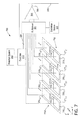
- FIG. 2 is a schematic illustration of one embodiment of a capacitive sensing system 200 that may be employed in one embodiment of the power cutting tool 100 .
- the capacitive sensing system 200 employs an electromagnetic field sensing arrangement.
- the power cutting tool is a table saw comprising a table top or the cutting surface 102 , the saw blade 104 , and the frame structure 106 above and spaced-apart from the cutting surface 102 as shown in FIGS. 1A-C .
- the table electrode matrices 108 A-D are vertically spaced apart from the frame electrode matrices 116 A-D along the z axis and are positioned substantially in parallel with respect to each other.
- the table electrode matrices 108 A-D may be located on the cutting surface 102 and the frame electrode matrices 116 A-D may be located on the overhead frame structure 106 .
- the capacitive sensing system 200 illustrates the cross-coupling between the respective electrode matrices 108 A-B, 116 A-B.
- the electrode matrices 108 A-D, 116 A-D may comprise individual conductive electrode elements 110 formed of various sizes and shapes and may be small relative to the wavelength of the excitation signal.
- the electrode elements 110 may be driven or excited with a voltage or excitation source.
- the current sourced into or out of each electrode element 110 may be measured by one or more electronic elements (e.g., amplifiers, conditioning circuits).
- the electrical currents sourced to the electrode elements 110 are proportional or sensitive to the dielectric constant and conductivity of objects 202 located in the region in proximity to or between the electrode elements 110 , and the coupling of those objects to other electrodes in the system.
- capacitances C 1 -C 5 are shown to assist in the understanding of the operation of the capacitive sensing system 200 . Accordingly, the capacitances C 1 , C 2 , and C 3 (as shown to the left of the saw blade 104 ) are background capacitances measured without the presence of the object 202 between the electrode matrices 108 A-D and 116 A-D. When the object 202 is located or enters the space between the electrode matrices 108 B and 116 B, the background capacitances C 1 , C 2 , and C 3 may change in multiple ways.
- the object 202 may decrease the coupling between the electrode matrices 108 B and 116 B and thus C 1 may decrease.
- the capacitance between the frame electrode matrix 116 B and the object 202 may increase as a result of new, parallel conductive paths formed by C 4 and C 5 .
- the capacitance C 2 may increase because capacitors C 4 and C 5 are now in parallel with it.
- the net effect on any capacitance measurement may be an increase or a decrease in capacitance, depending on the conductivity or impedance of the object 202 , the dielectric constant of the object 202 , and the proximity of the object 202 to other terminals (e.g., ground).
- the capacitive sensing system 200 provides information useful to differentiate between various objects 202 formed of different materials while maintaining sensitivity at some distance above the cutting surface 102 .
- the capacitive sensing system 200 may be configured to be sensitive to the bulk properties of the object 202 in the region proximate or between the electrode matrices 108 A-D and 116 A-D where one type of material does not necessarily shield another. This may be employed, for example, to detect a human hand under a workpiece that is approaching the saw blade 104 . In addition, clothing is unlikely to mask the ability to sense the human hand.
- the capacitive sensing system 200 may be employed to sense the object 202 in multiple modes, each of which is discussed in more detail below.
- the table electrode matrices 108 A-D located on the cutting surface 102 and the overhead frame electrode matrices 116 A-D located in the frame 114 establish electric fields therebetween along the z axis.
- the electric fields may be established between neighboring or adjacent electrode elements 110 of either the table electrode matrices 108 A-D or the frame electrode matrices 116 A-D along either the x or y axes.
- Variability in the dielectric constant and the conductivity of the object 202 will cause variable interruptions or current drains from the field lines 118 , allowing determination of the position of sensed materials or objects based on the location of the affected electrode elements 110 or sensing nodes of either the table electrode matrices 108 A-D or the frame electrode matrices 116 A-D.
- the object 202 may be detected utilizing the electric fields established between neighboring or adjacent electrode elements 110 of the table electrode matrices 108 A-D to sense materials or objects 202 moving along the cutting surface 102 along the x axis.
- the object 202 may be detected utilizing the electric fields established between the neighboring or adjacent electrode elements 110 of the frame electrode matrices 116 A-D to sense materials or objects 202 moving along the cutting surface 102 in the detection zones.
- These various modes of operation may be employed simultaneously, sequentially, or randomly by alternatively energizing a predetermined pair of electrode elements in any one of the matrices 108 A-D, 116 A-D.
- the electric field strength or drain current can be sensed by sensing a change in the capacitor formed by an energized pair of electrode elements to detect the presence of the object 202 .
- the sensing system 200 such as illustrated in FIGS. 1A-C and 2 may sense proximity of the object 202 to the blade 104 and may prevent a slip condition to prevent the object 202 from contacting the blade 104 by physically blocking the object 202 from the blade 104 by the frame 114 . It is also possible to sense conditions that should trigger the reaction system 314 ( FIG. 3 ) at a higher elevation above the table top 102 than can generally be achieved with a capacitive sensing system embedded in the table alone.
- FIG. 3A illustrates one embodiment of a capacitive sensing system 300 for one embodiment of a power cutting tool.
- the capacitive sensing system 300 may be coupled with the power cutting tool 100 and the capacitive sensing system 200 described in FIGS. 1A-C and 2 .
- an excitation source 302 is coupled to a multiplexer 304 to excite or energize the capacitors in a capacitor sensor matrix 308 comprising a top matrix C 1 and a bottom matrix C 2 positioned substantially parallel relative to each other.
- the top matrix C 1 comprises arrays of conductive electrode elements (e.g., frame electrode matrices 116 A, 116 B, 116 C, and 116 D) and the bottom matrix C 2 comprises arrays of conductive electrode elements (e.g., table electrode matrices 108 A, 108 B, 108 C, and 108 D).
- the capacitors may be formed by energizing pairs of the electrode elements in one of multiple modes forming multiple sensing nodes.
- the multiplexer 304 excites individual capacitors in the capacitor sensor matrix 308 .
- the individual capacitors in the capacitor sensor matrix 308 may be excited simultaneously, sequentially, or randomly.
- the multiplexer 304 may comprise additional switching logic or switch matrix circuitry to couple the excitation source 302 to a predetermined capacitor in the capacitor sensor matrix 308 .
- either the top matrix C 1 or the bottom matrix C 2 may be formed of a conductive structure or surface such as the frame structure 106 , the upper frame 114 , the table top or cutting surface 102 , the saw blade 104 , throat plate, power line, terminal connected to a common return path for electric current of the motor, or any other suitable conductive structure that may be used as an electrode element of the sensing array.
- the capacitors are formed by energizing the arrays of conductive electrode elements (e.g., table electrode matrices 108 A, 108 B, 108 C, and 108 D) of the bottom matrix C 2 relative to the conductive structure.
- conductive electrode elements e.g., table electrode matrices 108 A, 108 B, 108 C, and 108 D
- the capacitors are formed by energizing the arrays of conductive electrode elements (e.g., frame electrode matrices 116 A, 116 B, 116 C, and 116 D) of the top matrix C 1 relative to the conductive structure.
- conductive electrode elements e.g., frame electrode matrices 116 A, 116 B, 116 C, and 116 D
- a detection circuit 306 may be coupled to the capacitor sensor matrix 308 to detect any changes in capacitance of any capacitor.
- the detection circuit 306 may comprise multiple detection elements coupled to each capacitor in the capacitor sensor matrix 308 .
- the detection circuit 306 may be implemented as an array of individual amplifiers/detectors.
- the detection circuit 306 may comprise a single detection element (e.g., amplifier/detector) coupled to the capacitor sensor matrix 308 by way of a switching matrix to allow sequential or random coupling or connection to the individual energized electrode pairs forming sensing nodes.
- the multiplexer 304 couples a predetermined capacitor at a sensing node to a corresponding predetermined detection circuit 306 based on the operational mode.
- the multiplexer 304 receives mode select inputs 320 from a controller 312 or other processing device.
- the controller 312 receives the output of the detection circuit 306 and, when appropriate, provides a signal to register an activation condition when the detection circuit 306 senses a change in capacitance in any of the capacitor sensing nodes of the capacitor sensor matrix 308 that is determined to be representative of an object intrusion.
- the capacitance at a sensing node may change when an object comes close (e.g., in proximity) to an energized electrode pair.
- the change in capacitance may be a result of the object 202 being located in the region near, around, proximate, and/or between a pair of electrode elements.
- the detection circuit 306 provides a signal to the controller 312 and it is registered as an activation.
- the controller 312 may comprise preprogrammed threshold levels to determine if the change in capacitance should be registered as an activation event.
- an activation event may be coupled to one or more reaction systems 314 , such as those which either retract and/or stop the blade when certain conditions are detected.
- One such reaction system for example, retracts the blade from the cutting zone when certain conditions are detected, is described in U.S. patent application Ser. No. 11/589,344, filed 30 Oct. 2006, which is hereby incorporated by reference.
- the reaction system 314 for the power cutting tool 100 may reduce the RPM of the motor spinning the saw blade 104 when the certain conditions are detected such as the presence of the object 202 in proximity of or between the energized electrode element pairs.
- reaction system may sound an audible alarm when certain conditions are detected and/or provide a visual indication that the condition(s) has been detected.
- the table top or cutting surface 102 and/or the overhead frame structure 106 may comprise flashing lights that are energized and/or triggered by the reaction system 314 in response to the sensing system 300 detecting the object 202 .
- FIG. 3B illustrates one embodiment of a capacitor sensor matrix 308 .
- the capacitor sensor matrix 308 may be formed as a portion of the table electrode matrix 108 A and the frame electrode matrix 116 A configured to operate in a first mode, for example.
- the operation of the capacitor sensor matrix 308 in the first mode is described with reference to the table electrode matrix 108 A and the frame electrode matrix 116 A.
- the principles of operation also apply to the matrices 108 B-D and 116 B-D.
- the table electrode matrix 108 A may comprise i rows distributed along the x axis and j columns distributed along the y axis to form a two-dimensional array of electrically conductive electrode elements 110 1,1 to 110 i,j .
- the frame electrode matrix 116 A also may comprise i rows distributed along the x axis and j columns distributed along the y axis to form a two-dimensional array of electrically conductive electrode elements 310 1,1 to 310 i,j .
- the capacitive sensing system 300 may be formed as an array of pairs of respective electrically conductive electrode elements 110 1,1 / 310 1,1 to 110 i,j / 310 i,j spaced apart vertically along the z axis and positioned in parallel relative to each other.
- the array of pairs of respective electrically conductive electrode elements 110 1,1 / 310 1,1 to 110 i,j / 310 i,j are energized by the excitation source 302 to create the field lines 118 and form corresponding capacitors C 1,1 to C i,j , which may be referred to as the sensing nodes.
- the table electrode matrix 108 A may be configured as a single conductive structure such as the table top or cutting surface 102 , a power line, throat plate, a terminal connected to a common return path for electric current of the motor, or any other suitable conductive structure that may be used as an electrode element of the sensing array.
- the frame electrode matrix 116 A may be configured as a single conductive structure such as the frame structure 106 , the upper frame 114 , and the saw blade 104 . The embodiments are not limited in this context.
- the multiplexer/switching matrix 304 couples the corresponding pair of vertically separated electrically conductive electrode elements 110 1,1 / 310 1,1 to 110 i,j / 310 i,j to the excitation source 302 to form sensing node capacitors C 1,1 to C i,j .
- the multiplexer/switching matrix 304 also may be employed to couple the capacitors C 1,1 to C i,j to the corresponding detection circuit elements 306 1,1 to 306 i,j ( FIG. 3C ).
- the capacitor C 1,1 sensing node is formed by coupling the excitation source 302 to the pair of electrically conductive electrode elements 110 1,1 and 310 1,1 using the multiplexer/switch matrix 304 and energizing these electrically conductive electrode elements 110 1,1 and 310 1,1 with a suitable amount of energy to create the field lines 118 .
- the pairs of electrically conductive electrode elements are denoted as ( 110 / 310 ) i,j .
- These electrode elements ( 110 / 310 ) 1,1 to ( 110 / 310 ) i,j are coupled to the corresponding detection circuit elements 306 1,1 to 306 i,j .
- the excitation source 302 energizes (e.g., creates a voltage differential to create an electric field) the electrode element pairs ( 110 / 310 ) 1,1 to ( 110 / 310 ) i,j (e.g., sensing nodes) either simultaneously, sequentially, or randomly.
- the electrical current enters or leaves the electrode element pairs ( 110 / 310 ) 1,1 to ( 110 / 310 ) i,j and sets up an electric field as indicated by the vertical field lines 118 .
- the electrode element pairs ( 110 / 310 ) 1,1 to ( 110 / 310 ) i,j may be arranged to operate in pairs and may be oriented orthogonally and/or parallel relative to each other and operate in pairs to form the corresponding capacitors C 1,1 to C i,j .
- a high frequency signal from the excitation source 302 may be applied to the electrode element pairs ( 110 / 310 ) 1,1 to ( 110 / 310 ) i,j .
- the current that passes through the electrode element pairs ( 110 / 310 ) 1,1 to ( 110 / 310 ) i,j is proportional to the capacitance between the first and second electrode element pairs, which are denoted as respective capacitances C 1,1 to C i,j .
- FIG. 3C illustrates one embodiment of a detection circuit 306 coupled to the capacitor sensor matrix 308 to detect changes in capacitance of any of the capacitive sensing nodes of the capacitor sensor matrix 308 .
- the detection circuit 306 comprises multiple detection circuits 306 1,1 - 306 i,j coupled to each respective capacitor C 1,1 to C i,j sensing node and configured to detect any change in their capacitance.
- the detection circuit 306 may be configured to detect any change in the capacitance between the respective electrode element pair ( 110 / 310 ) 1,1-i,j and provides a corresponding detection signal 318 i,j to the controller 312 via a bus 316 , for example.
- the detection signals 318 i,j may indicate a sensed condition to the controller 312 when they exceed a predetermined threshold.
- the detection signal 318 i,j may be digital or analog.
- the controller 312 outputs a signal to the reaction system 314 when the detection signal 318 i,j exceeds the predetermined threshold.
- FIG. 4 illustrates one embodiment of a capacitive sensing system 400 operating in a first mode.
- FIG. 4 also illustrates distortion or interference of the field lines 118 when a virtual ground or impedance point, such as the object 202 , is placed between or in proximity to the sensing node formed by electrode element pair ( 110 / 310 ) 1,1 , for example.
- the object 202 interferes with the field lines 118 created between the energized electrode element pair ( 110 / 310 ) 1,1 .
- some of the vertical field lines 118 from the first electrode 110 1,1 are shunted and do not reach the second electrode 310 1,1 resulting in a change in the apparent capacitance at that sensing node as described in FIG. 2 , for example.
- the vertical field lines 118 are shunted to the same ground or impedance point connected to the excitation source 302 resulting in a change in the apparent capacitance at that sensing node as described in FIG. 2 .
- the capacitive shunt detection method senses the change in capacitance between a transmitter node coupled to the first electrode 110 1,1 and a receiver node coupled to the second electrode 310 1,1 .
- the transmitter node e.g., the first electrode 110 1,1
- the receiver node e.g., the second electrode 310 1,1
- the transmitter creates an oscillating electric field. If a ground or impedance point, such as the object 202 to be detected, is placed proximately or in between the transmitter and receiver nodes (e.g., electrodes 110 1,1 / 310 1,1 ), some of the vertical field lines 118 are shunted away, decreasing the apparent capacitance at the sensing node and the total capacitance measured at the receiver node electrode 310 1,1 decreases.
- FIG. 5 illustrates one embodiment of a capacitive sensing system 500 operating in a second and a third mode.
- the second and third modes of operation of the capacitor sensor matrix 308 in the capacitive sensing system 500 are described with reference to the table electrode matrix 108 A and the frame electrode matrix 116 A portions of the capacitor sensor matrix 308 .
- the principles of operation also apply to the matrices 108 B-D and 116 B-D.
- a table capacitor matrix system 510 comprises a two-dimensional array of (i ⁇ 1) ⁇ (j) individual capacitors formed by energizing neighboring electrode elements in the table x-y plane.
- a capacitor C′ 1,1 sensing node may be formed by energizing adjacent neighboring electrode elements 110 1,1 and 110 2,1 of the table electrode matrix 108 A along the x axis with the excitation source 302 and generating an electric field represented by field lines 518 .
- the table electrode matrix 108 A comprises up to (i ⁇ 1) individual capacitors C′ 1,1 , C′ 2,1 . . .
- the multiplexer/switching matrix 304 may be configured to couple the appropriate adjacent electrode element pairs ( 110 1,1 / 110 2,1 )-( 110 i-1,1 / 110 i,1 ) to form capacitors C′ 1,1 -C′ i-1,1 and coupling these capacitors to the corresponding detection circuits 306 1,1 - 306 i-1,1 , which are generally shown as detection circuit 306 for clarity of illustration.
- the individual detection circuits 306 1,1 - 306 i-1,1 are configured to detect any capacitance change in the capacitors C′ 1,1 -C′ i-1,1 that may occur when the object 202 is placed proximately thereto and thus interrupting, shunting, or otherwise distorting the field lines 518 between any of the capacitors C′ 1,1 -C′ i-1,1 .
- the same principles may be applied to the remaining j columns in the table capacitor matrix 510 along the y axis.
- a frame capacitor matrix 512 comprises a two-dimensional array of (i ⁇ 1) ⁇ (j) individual capacitors formed by energizing neighboring electrode elements in the frame x′-y′ plane, which may be parallel to the table x-y plane.
- a capacitor C′′ 1,1 sensing node may be formed by energizing adjacent neighboring electrode elements 310 1,1 and 310 2,1 of the frame electrode matrix 116 A along the x′ axis with the excitation source 302 and generating an electric field represented by field lines 520 .
- the table electrode matrix 116 A comprises up to (i ⁇ 1) individual capacitors C′′ i-1,1 , C′′ 2,1 . . .
- C′′ i-1,1 formed by sequentially or randomly energizing adjacent electrode element pairs ( 310 1,1 / 310 2,1 ), ( 310 2,1 / 310 3,1 ) . . . to ( 310 i-1,1 / 310 i-1 ) along the x′ axis in the x′-y′ plane, for example.
- the multiplexer/switching matrix 304 may be configured to couple the appropriate pairs of adjacent electrode element pairs ( 310 1,1 / 310 2,1 )-( 310 i-1,1 / 310 i-1,1 ) to form capacitors C′′ 1,1 -C′′ i-1,1 and coupling these capacitors to the corresponding detection circuits 306 1,1 - 306 i-1,1 , which are generally shown as detection circuit 306 for clarity of illustration.
- the individual detection circuits 306 1,1 - 306 i-1,1 are configured to detect any capacitance change in the capacitors C′′ 1,1 -C′′ i-1,1 that may occur when the object 202 is placed in proximately thereto and thus interrupting, shunting, or otherwise distorting the field lines 520 .
- the same principles may be applied to the remaining j columns in the frame capacitor matrix 510 .
- FIG. 6 illustrates one embodiment of a capacitive sensing system 600 operating in a fourth mode.
- the fourth mode of operation of the capacitor sensor matrix 308 in the capacitive sensing system 600 is described with reference to the table electrode matrix 108 A portion of the capacitor sensor matrix 308 .
- the same principles may be applied to the other portions of the table electrode matrices 108 B-D.
- a fourth table capacitor matrix 610 (C′′′) comprises a two-dimensional array of (i) ⁇ (j ⁇ 1) individual capacitors formed by energizing neighboring electrode elements on the horizontal x-y plane.
- a capacitor C′′′ 1,1 sensing node may be formed when the excitation source 302 energizes adjacent neighboring electrode elements 110 1,1 and 110 1,2 of the table electrode matrix 108 A along the y′ axis and generating an electric field represented by field lines 618 .
- the table electrode matrix 108 A comprises up to (j ⁇ 1) individual capacitors C′′′ 1,1 , C′′′ 1,2 . . .
- the multiplexer/switching matrix 304 may be configured to couple the appropriate adjacent electrode element pairs ( 110 1,1 / 110 1,2 )-( 110 1,j-1 / 110 1,j ) to form capacitors C′′′ 1,1 -C′′′ 1,j-1 and coupling these capacitors to the corresponding detection circuits 306 1,1 - 306 1,j-1 , which are generally shown as detection circuit 306 for clarity of illustration.
- the individual detection circuits 306 1,1 - 306 1,j-1 are configured to detect any capacitance change in the capacitors C′′′ 1,1 -C′′′ 1,j-1 that may occur when the object 202 is placed in proximity thereto and thus interrupting, shunting or otherwise distorting the field lines 618 .
- the same principles may be applied to the remaining i rows in the table capacitor matrix 610 .
- FIG. 7 illustrates one embodiment of a capacitive sensing system 700 operating in a fifth mode.
- the fifth mode of operation of the capacitor sensor matrix 308 of the capacitive sensing system 700 is described with reference to the frame electrode matrix 116 A portion of the capacitor sensor matrix 308 .
- the same principles may be applied to the other portions of the table and frame electrode matrices 116 B-D.
- a fifth frame capacitor matrix 710 comprises a two-dimensional array of (i) ⁇ (j ⁇ 1) individual capacitors formed by energizing neighboring electrode elements on the horizontal x′-y′ plane.
- a capacitor C′′′′ 1,1 may be formed when the excitation source 302 energizes adjacent neighboring electrode elements 310 1,1 and 310 1,2 of the table electrode matrix 116 A along the y′ axis and generating an electric field represented by field lines 718 .
- the table electrode matrix 116 A comprises up to (j ⁇ 1) individual capacitors C′′′′ 1,1 , C′′′′ 1,2 . . .
- C′′′′ 1,j-1 formed by sequentially or randomly energizing adjacent electrode element pairs ( 310 1,1 / 310 1,2 ), ( 310 1,2 / 310 1,3 ) . . . to ( 310 1,j-1 / 310 1,j ) along the y′ axis in the x′-y′ plane, for example.
- the multiplexer/switching matrix 304 may be configured to couple the appropriate horizontally adjacent electrode element pairs ( 310 1,1 / 310 1,2 )-( 310 1,j-1 / 310 1,j ) to form capacitors C′′′′ 1,1 -C′′′′ 1,j-1 and coupling these capacitors to the corresponding detection circuits 306 1,1 - 306 1,j-1 , which are generally shown as detection circuit 306 for clarity of illustration.
- the individual detection circuits 306 1,1 - 306 1,j-1 are configured to detect any capacitance change in the capacitors C′′′′ 1,1 -C′′′′ 1,j-1 that may occur when the object 202 is placed proximately thereto and thus interrupting, shunting, or otherwise distorting the field lines 718 .
- the same principles may be applied to the remaining i rows in the frame capacitor matrix 710 .
- the velocity of the object 202 approaching or withdrawing from the blade 104 of the power cutting tool 100 may be determined by sensing the object 202 in an outer detection zone around the blade 104 .
- the detection zone may be formed by 108 A-D or 116 A-D and comprises an array of electrical conductors 110 i,j and 310 i,j .
- the object 202 may be sensed as it traverses between a first electrical conductor 110 1,1 and a second electrical conductor 110 2,1 of the electrode matrix 108 A, for example.
- the controller 312 can compute the time difference between when the object was detected at the first electrical conductor 110 1,1 and when the object was detected at the second electrical conductor 110 2,1 .
- the same principles may be applied to determine the velocity of the object 202 as it traverses any two or more electrical conductors of any of the electrode matrices discussed above.
Abstract
A power cutting tool includes a cutting surface, a conductive structure, and first electrode matrix comprising an array of electrical conductors. A moveable blade used to cut an object is located on the cutting surface. When at least one electrical conductor of the first electrode matrix is energized relative to the conductive structure, an electric field extends between the at least one electrical conductor and the conductive matrix to detect the presence of an object in proximity to the electric field.
Description
This application is a continuation of U.S. application Ser. No. 12/273,877, filed Nov. 19, 2008 now abandoned, titled “POWER CUTTING TOOL WITH PROXIMITY SENSING SYSTEM,” which is incorporated herein by reference in its entirety.
The present disclosure generally relates to sensing or detecting systems, and more particularly to sensing or detecting systems for power cutting tools.
Detection or sensing systems have been developed for use with various kinds of manufacturing equipment and power tools. Such detection systems are operable to trigger some type of reaction mechanism when certain conditions are sensed or detected. For example, it is known to use a capacitive contact sensing system to detect contact between an operator and a blade of a table saw. In such systems, a signal may be capacitively coupled to the blade and the signal on the blade is monitored to detect changes in the signal indicative of contact between the operator and the blade. Such capacitive sensing systems, however, are only practically able to detect contact between the operator and the blade. Such systems cannot practically detect the proximity of the operator to the blade. Detection systems to detect when the operator or other object comes near or in proximity to the blade may be desirable.
In one embodiment, a power cutting tool comprises a cutting surface, a conductive structure, a moveable blade to cut an object located on the cutting surface, and a first electrode matrix comprising an array of electrical conductors. When at least one electrical conductor of the first electrode matrix is energized relative to the conductive structure, an electric field extends between the at least one electrical conductor and the conductive matrix to detect the presence of an object in proximity to the electric field.
The embodiments are directed generally to (i) a proximity sensing system for a power cutting tool and (ii) a power cutting tool, such as a table saw, comprising the sensing system for detecting certain conditions with respect to the blade of the cutting tool. There are several embodiments disclosed herein that relate to overhead frame supports for sensing the presence of an object in proximity to the rotating blade of a table saw. While the embodiments that are shown and described below are implemented in the environment of a table saw, it should be understood that they could also be implemented in other types of power cutting tools, such as miter saws, chop-saws, arm saws, band saws, etc. The use of an overhead frame structure enables accurate detection of the proximity of an object in the detection zones.
One embodiment is directed to a power cutting tool, such as a table saw, comprising a sensing system for detecting a condition with respect to an exposed, moveable blade of the power cutting tool. Several embodiments of the sensing system comprise at least one sensor located above the blade and positioned to (1) monitor one or more volume zones adjacent the blade, (2) detect when an object enters one or more of the zones, and (3) trigger a reaction system in response to the detection.
According to various embodiments, the sensing system comprises a frame connected to the cutting platform (e.g., a table where the power cutting tool is a table saw). The frame may be spaced apart from and parallel to the cutting surface, and may surround at least a portion the blade. The frame may comprise an arrangement of frame sensing elements. In one embodiment, the frame sensing elements may comprise an arrangement of electrically conductive electrode elements arranged in n (rows)×m (columns) (where n=m in certain embodiments, but in other embodiments n≠m) facing the electrically conductive frame and may be referred to herein as a frame electrode matrix. The elements may be arranged in a rectangular pattern and may be positioned adjacent to each other. In one embodiment, the elements may be arranged in a rectangular pattern and may be positioned substantially parallel to each other. The sensing system also may comprise an arrangement of table sensing elements. In one embodiment, the table sensing elements may comprise an electrically conductive region on the cutting surface. The electrically conductive region also may comprise an arrangement of electrically conductive electrode elements arranged in i (rows)×j (columns) (where i=j in certain embodiments and where i=n and j=m in certain embodiments) and referred to herein as a table electrode matrix. These elements also may be arranged in a rectangular pattern and may be positioned orthogonally relative to each other. When energized, one or more electric fields may extend between: (1) the individual electrode elements of the table electrode matrix and the frame electrode matrix; (2) the individual electrode elements of the frame electrode matrix; (3) the individual electrode elements of the table electrode matrix; and/or (4) any combination of these configurations to form individual capacitors. Changes in the electric field between any electrode elements of the matrices may indicate a condition proximate to the blade, which may be used to trigger the reaction system.
In various other embodiments, the sensing system comprises a plurality of electrode elements forming one first of a capacitive matrix and a suitable conductive structure (e.g., a conductive surface) forming a second side of the capacitive matrix. The conductive structure forming the second side of the capacitive matrix may be the frame, the table, the saw blade, throat plate, power line, terminal connected to a common return path for electric current of the motor, or any other suitable conductive structure that may be used as an electrode element of the sensing array. In one embodiment, the conductive structure may be used as one side of the sensing element. Therefore, a plurality of electrode elements may be arranged to form individual capacitors between the plurality of electrode elements and the conductive object. When energized, one or more electric fields may extend between the conductive structure and the individual electrode elements. Changes in the electric field between any electrode elements and the conductive structure indicate a condition proximate to the blade, which may be used to trigger the reaction system.
The sensing and/or detection systems described herein may be used with a reaction system, such as those which either retract and/or stop the blade when certain conditions are detected. One such reaction system, which retracts the blade from the cutting zone when certain conditions are detected, is described in U.S. patent application Ser. No. 11/589,344, filed 30 Oct. 2006, which is hereby incorporated by reference. In addition to or in lieu of such a reaction system, the reaction system for the power cutting tool may reduce the RPM of the motor spinning the blade when the certain conditions are detected. Additionally, the reaction system may sound an audible alarm when certain conditions are detected and/or provide a visual indication that the condition(s) has been detected.
Various embodiments of the sensing system may comprise an n×m frame electrode matrix and an i×j table electrode matrix. For convenience and clarity the following embodiments of frame and table electrode matrices will be described as matrices comprising i×j electrode elements, where n=i and j=m. In various embodiments, the sensing system may be formed by a 1×1 element matrix wherein either n=m=1 or i=j=1. For example, n=m=1 when a conductive structure such as the frame forms one first of the capacitive matrix. Similarly, i=j=1 when a conductive structure such as the conductive table forms a first side of the capacitive matrix. The frame and table electrode matrices may operate either individually or in combination on similar principles. An electrode matrix may comprise an array of electrical conductors. Electrical voltage differential across the electrode pairs creates an electric field between the electrode pair and thus forms a capacitor with air acting as the dielectric between the electrode pair. Those skilled in the art will appreciate that the electric current into or out of an electrode is proportional to the rate of change of the electric field in the region near the electrode. Each energized electrode pair may be referred as a sensing node. The electrodes may be arranged as a uni-dimensional or multi-dimensional array of electrical conductors separated by air (or other dielectric). The electrodes may be oriented orthogonally, adjacent, and/or in parallel relative to each other and operate in pairs to form one or more sensing nodes at desired locations on the power cutting tool.
A high frequency signal from an excitation source may be applied sequentially between pairs of first and second electrodes (e.g., sensing nodes) in the electrical conductor array or sensing matrix. The excitation source may be coupled to first and second electrodes to generate an electric field between the electrode pair. The current that passes between the first and second electrodes is proportional to the capacitance of the electrode pair. More generally, the shape of the electric field in the region near the electrodes depends on both the differential voltages applied to the electrodes and on the dielectric constant and conductivity of the objects in proximity of the region. Electrodes may be driven in order to shape the field to optimize detection of objects in a particular region. Varying the field with time or applying a high-frequency excitation voltage, for example, allows the local field strength near each electrode to be measured by measuring the amount of current drawn into or out of each electrode. Therefore, any suitable configuration of electrodes and differential voltages applied thereto that optimizes the difference in the changes to the electric field that is caused by objects (e.g., wood, fingers) in the region in proximity to or between the electrodes may be employed. Electrodes that are not part of the table or the guard (such as the outer table surface, the throat plate, or the blade) may influence setting up the right field configuration, even if they are not sensed as part of the detection system.
The electrode sensing matrices may be operated in multiple modes. To accommodate multi-mode operation of the sensing matrices, in one embodiment, a multiplexer and a switching matrix may be employed to couple selectively the excitation source to the desired electrode pair and to couple a detection circuit to the electrode pair to monitor the effects on capacitance therebetween. The electrode pairs forming the sensing matrices may be excited simultaneously, sequentially, or randomly. Switching between the multiple modes may occur in real time, e.g. “on-the-fly.” An object placed in proximity of any energized electrode pairs changes the electric field configuration and thereby changes the capacitance between at least one electrode pair, producing a signal that can be sensed. This may be referred to as a capacitive shunt. For example, when the object is placed in proximity of any energized electrode pairs, some of the electrical field lines from the first electrode are shunted by the object and do not reach the second electrode. This results in a change in the apparent capacitance at that location.
When an object is placed between or in proximity of any sensing node, the change in capacitance between a transmitter coupled to the first electrode and a receiver coupled to the second electrode may be sensed by a detection circuit. The transmitter may be used to provide an excitation source to create an oscillating electric field. If a ground/impedance point, such as an object to be detected, is placed between or in proximity to the transmitter and receiver node electrodes, some of the field lines are shunted away, thus decreasing the apparent capacitance at that point. Accordingly, the total capacitance measured at the receiver node electrode decreases when an object comes close to or in proximity of the induced field at the sensing node. This decrease in capacitance may be sensed by a detection circuit.
In one embodiment, one or more detection circuits may be coupled to the capacitor sensor matrix formed by the various array configurations of electrode pairs. In one embodiment, a single detection circuit may be coupled to the capacitor sensor matrix by way of a switching matrix. In either embodiment, the detection circuits are suitable to detect significant changes in the capacitance at the sensing nodes of the capacitor sensor matrix when an object is located near (e.g., in proximity) the activated electrode pair. In another embodiment, this may be referred to herein as the detection zone of a sensing node. A controller may be coupled to the detection circuits to register activations when an object is located in the detection zone such that the total capacitance between the electrode pair of the sensing node changes to such an extent as to exceed a predetermined threshold level. The controller may comprise preprogrammed threshold levels to determine if the change in capacitance should be registered as an activation event. When the change in capacitance exceeds the predetermined threshold, the controller registers an activation and provides a signal to a reaction system to stop and/or retract the saw blade in the cutting tool, for example.
In the illustrated embodiment, the frame structure 106 may comprise a vertically oriented splitter 112 in the y-z plane positioned behind the blade 104 that extends forwardly over a portion of the exposed blade 104. The splitter 112 may reduce the risk of a kick back condition. The frame structure 106 also may comprise an electrically conductive upper frame 114 mounted to the splitter 112 that generally surrounds the blade 104 above the cutting surface 102. In the illustrated embodiment, the upper frame 114 is rectangular and may be approximately the same size as the table electrode matrices 108A-D on the table top, but spaced apart from the table electrode matrices 108A-D by a distance that varies in accordance with the height of the frame 106 relative to the surface, which may vary with the height of the blade 104. This is because the splitter 112 is preferably connected to the frame structure of the blade assembly so that as the blade 104 is elevated or lowered, the splitter 112 maintains a relatively close spacing relationship with the blade 104 as shown in FIG. 1A . Accordingly, the splitter 112 (and hence the upper frame 114) may move up and down with the blade 104. Thus, the distance between the upper frame 114 and the table electrode matrices 108A-D can vary.
The table electrode matrices 108A-D located on or adjacent to the cutting surface 102 may be positioned substantially parallel with the frame electrode matrices 116A-D, respectively. The frame structure 106 surrounds the saw blade 104. In the illustrated embodiment, the table electrode matrices 108A-B and the respective frame electrode matrices 116A, B are located on either side of the saw blade 104. The table electrode matrix 108C and the respective frame electrode matrix 116C are located in front of the saw blade 104. And the table electrode matrix 108D and the respective frame electrode matrix 116D are located in the rear of the saw blade 104. The table electrode matrices 108A-D and the corresponding frame electrode matrices 116A-D preferably comprise electrically conductive electrode elements 110. In the illustrated embodiment, the electrically conductive electrode elements 110 are formed as rectangular elements, although in other embodiments electrically conductive electrode elements may be formed of any suitable shape and/or dimension.
The electrically conductive electrode elements 110 may be electrically energized in pairs to form a capacitive sensing node within the capacitor sensor matrix. The electrode pair may be energized relative to each other with an excitation source having sufficient voltage to produce electric field lines 118 that extends between the electrode pair. The electric field is diagrammatically illustrated as curved field lines 118 extending between the energized electrode pair. As diagrammatically illustrated in FIGS. 1B and 1C , in one embodiment, the field lines 118 are formed between electrode pairs spaced apart vertically in the z direction. The capacitance between the electrode pairs is monitored so that if an object is brought into or near the electric field, the capacitance will necessarily change. If the change in capacitance exceeds a predetermined threshold, it may trigger the reaction system. Processing circuitry located in a detection circuit 306 (FIG. 3 ) or a controller 312 (FIG. 3 ) can differentiate between various conditions to appropriately trigger the reaction system when a hand of a person, or portion thereof, is detected within the field lines 118.
In one embodiment, the table electrode matrices 108A-D may be located on the cutting surface 102 and the frame electrode matrices 116A-D may be located on the overhead frame structure 106. The capacitive sensing system 200 illustrates the cross-coupling between the respective electrode matrices 108A-B, 116A-B. As previously discussed, the electrode matrices 108A-D, 116A-D may comprise individual conductive electrode elements 110 formed of various sizes and shapes and may be small relative to the wavelength of the excitation signal. The electrode elements 110 may be driven or excited with a voltage or excitation source. The current sourced into or out of each electrode element 110 may be measured by one or more electronic elements (e.g., amplifiers, conditioning circuits). The electrical currents sourced to the electrode elements 110 are proportional or sensitive to the dielectric constant and conductivity of objects 202 located in the region in proximity to or between the electrode elements 110, and the coupling of those objects to other electrodes in the system.
For convenience and clarity, capacitances C1-C5 are shown to assist in the understanding of the operation of the capacitive sensing system 200. Accordingly, the capacitances C1, C2, and C3 (as shown to the left of the saw blade 104) are background capacitances measured without the presence of the object 202 between the electrode matrices 108A-D and 116A-D. When the object 202 is located or enters the space between the electrode matrices 108B and 116B, the background capacitances C1, C2, and C3 may change in multiple ways. For example, if the object 202 is grounded (or if the object 202 comprises a large capacitance or impedance to ground), it may decrease the coupling between the electrode matrices 108B and 116B and thus C1 may decrease. Alternatively, the capacitance between the frame electrode matrix 116B and the object 202 may increase as a result of new, parallel conductive paths formed by C4 and C5. Thus, the capacitance C2 may increase because capacitors C4 and C5 are now in parallel with it. The net effect on any capacitance measurement may be an increase or a decrease in capacitance, depending on the conductivity or impedance of the object 202, the dielectric constant of the object 202, and the proximity of the object 202 to other terminals (e.g., ground). Thus, the capacitive sensing system 200 provides information useful to differentiate between various objects 202 formed of different materials while maintaining sensitivity at some distance above the cutting surface 102.
The capacitive sensing system 200 may be configured to be sensitive to the bulk properties of the object 202 in the region proximate or between the electrode matrices 108A-D and 116A-D where one type of material does not necessarily shield another. This may be employed, for example, to detect a human hand under a workpiece that is approaching the saw blade 104. In addition, clothing is unlikely to mask the ability to sense the human hand.
The capacitive sensing system 200 may be employed to sense the object 202 in multiple modes, each of which is discussed in more detail below. In one mode of operation, the table electrode matrices 108A-D located on the cutting surface 102 and the overhead frame electrode matrices 116A-D located in the frame 114 establish electric fields therebetween along the z axis. In other modes, the electric fields may be established between neighboring or adjacent electrode elements 110 of either the table electrode matrices 108A-D or the frame electrode matrices 116A-D along either the x or y axes. Variability in the dielectric constant and the conductivity of the object 202 will cause variable interruptions or current drains from the field lines 118, allowing determination of the position of sensed materials or objects based on the location of the affected electrode elements 110 or sensing nodes of either the table electrode matrices 108A-D or the frame electrode matrices 116A-D. Alternatively or in conjunction therewith, in other modes of operation, the object 202 may be detected utilizing the electric fields established between neighboring or adjacent electrode elements 110 of the table electrode matrices 108A-D to sense materials or objects 202 moving along the cutting surface 102 along the x axis. In yet other modes, the object 202 may be detected utilizing the electric fields established between the neighboring or adjacent electrode elements 110 of the frame electrode matrices 116A-D to sense materials or objects 202 moving along the cutting surface 102 in the detection zones. These various modes of operation may be employed simultaneously, sequentially, or randomly by alternatively energizing a predetermined pair of electrode elements in any one of the matrices 108A-D, 116A-D. In any of these operating modes, the electric field strength or drain current can be sensed by sensing a change in the capacitor formed by an energized pair of electrode elements to detect the presence of the object 202.
In one embodiment, the sensing system 200 such as illustrated in FIGS. 1A-C and 2 may sense proximity of the object 202 to the blade 104 and may prevent a slip condition to prevent the object 202 from contacting the blade 104 by physically blocking the object 202 from the blade 104 by the frame 114. It is also possible to sense conditions that should trigger the reaction system 314 (FIG. 3 ) at a higher elevation above the table top 102 than can generally be achieved with a capacitive sensing system embedded in the table alone.
In various embodiments, either the top matrix C1 or the bottom matrix C2 may be formed of a conductive structure or surface such as the frame structure 106, the upper frame 114, the table top or cutting surface 102, the saw blade 104, throat plate, power line, terminal connected to a common return path for electric current of the motor, or any other suitable conductive structure that may be used as an electrode element of the sensing array. In the embodiment where the top matrix C1 is formed of a conductive structure or surface (e.g., the frame structure 106, the upper frame 114, the saw blade 104), the capacitors are formed by energizing the arrays of conductive electrode elements (e.g., table electrode matrices 108A, 108B, 108C, and 108D) of the bottom matrix C2 relative to the conductive structure. In the embodiment where the bottom matrix C2 is formed of a single conductive structure (the table top or cutting surface 102, a power line, throat plate, a terminal connected to a common return path for electric current of the motor), the capacitors are formed by energizing the arrays of conductive electrode elements (e.g., frame electrode matrices 116A, 116B, 116C, and 116D) of the top matrix C1 relative to the conductive structure. The embodiments, however, are not limited in this context.
A detection circuit 306 may be coupled to the capacitor sensor matrix 308 to detect any changes in capacitance of any capacitor. In one embodiment, the detection circuit 306 may comprise multiple detection elements coupled to each capacitor in the capacitor sensor matrix 308. The detection circuit 306 may be implemented as an array of individual amplifiers/detectors. In other embodiments, the detection circuit 306 may comprise a single detection element (e.g., amplifier/detector) coupled to the capacitor sensor matrix 308 by way of a switching matrix to allow sequential or random coupling or connection to the individual energized electrode pairs forming sensing nodes.
The multiplexer 304 couples a predetermined capacitor at a sensing node to a corresponding predetermined detection circuit 306 based on the operational mode. The multiplexer 304 receives mode select inputs 320 from a controller 312 or other processing device.
The controller 312 receives the output of the detection circuit 306 and, when appropriate, provides a signal to register an activation condition when the detection circuit 306 senses a change in capacitance in any of the capacitor sensing nodes of the capacitor sensor matrix 308 that is determined to be representative of an object intrusion. As previously discussed, the capacitance at a sensing node may change when an object comes close (e.g., in proximity) to an energized electrode pair. As described in FIG. 2 , the change in capacitance may be a result of the object 202 being located in the region near, around, proximate, and/or between a pair of electrode elements. If the total capacitance between the energized electrode pair changes to such an extent that a set threshold is exceeded, the detection circuit 306 provides a signal to the controller 312 and it is registered as an activation. The controller 312 may comprise preprogrammed threshold levels to determine if the change in capacitance should be registered as an activation event.
As previously discussed, an activation event may be coupled to one or more reaction systems 314, such as those which either retract and/or stop the blade when certain conditions are detected. One such reaction system, for example, retracts the blade from the cutting zone when certain conditions are detected, is described in U.S. patent application Ser. No. 11/589,344, filed 30 Oct. 2006, which is hereby incorporated by reference. In addition to or in lieu of such a reaction system, the reaction system 314 for the power cutting tool 100 may reduce the RPM of the motor spinning the saw blade 104 when the certain conditions are detected such as the presence of the object 202 in proximity of or between the energized electrode element pairs. Additionally, the reaction system may sound an audible alarm when certain conditions are detected and/or provide a visual indication that the condition(s) has been detected. In one embodiment, the table top or cutting surface 102 and/or the overhead frame structure 106 may comprise flashing lights that are energized and/or triggered by the reaction system 314 in response to the sensing system 300 detecting the object 202.
As previously discussed, in one embodiment, the table electrode matrix 108A may be configured as a single conductive structure such as the table top or cutting surface 102, a power line, throat plate, a terminal connected to a common return path for electric current of the motor, or any other suitable conductive structure that may be used as an electrode element of the sensing array. In another embodiment, the frame electrode matrix 116A may be configured as a single conductive structure such as the frame structure 106, the upper frame 114, and the saw blade 104. The embodiments are not limited in this context.
In the first mode of operation, the multiplexer/switching matrix 304 couples the corresponding pair of vertically separated electrically conductive electrode elements 110 1,1/310 1,1 to 110 i,j/310 i,j to the excitation source 302 to form sensing node capacitors C1,1 to Ci,j. The multiplexer/switching matrix 304 also may be employed to couple the capacitors C1,1 to Ci,j to the corresponding detection circuit elements 306 1,1 to 306 i,j (FIG. 3C ). For example, in the first mode of operation, the capacitor C1,1 sensing node is formed by coupling the excitation source 302 to the pair of electrically conductive electrode elements 110 1,1 and 310 1,1 using the multiplexer/switch matrix 304 and energizing these electrically conductive electrode elements 110 1,1 and 310 1,1 with a suitable amount of energy to create the field lines 118. For convenience and clarity the pairs of electrically conductive electrode elements are denoted as (110/310)i,j. These electrode elements (110/310)1,1 to (110/310)i,j are coupled to the corresponding detection circuit elements 306 1,1 to 306 i,j.
The excitation source 302 energizes (e.g., creates a voltage differential to create an electric field) the electrode element pairs (110/310)1,1 to (110/310)i,j (e.g., sensing nodes) either simultaneously, sequentially, or randomly. The electrical current enters or leaves the electrode element pairs (110/310)1,1 to (110/310)i,j and sets up an electric field as indicated by the vertical field lines 118. The electrode element pairs (110/310)1,1 to (110/310)i,j may be arranged to operate in pairs and may be oriented orthogonally and/or parallel relative to each other and operate in pairs to form the corresponding capacitors C1,1 to Ci,j. A high frequency signal from the excitation source 302 may be applied to the electrode element pairs (110/310)1,1 to (110/310)i,j. The current that passes through the electrode element pairs (110/310)1,1 to (110/310)i,j is proportional to the capacitance between the first and second electrode element pairs, which are denoted as respective capacitances C1,1 to Ci,j.
In the second mode of operation, a table capacitor matrix system 510 (C′) comprises a two-dimensional array of (i−1)×(j) individual capacitors formed by energizing neighboring electrode elements in the table x-y plane. As shown, a capacitor C′1,1 sensing node may be formed by energizing adjacent neighboring electrode elements 110 1,1 and 110 2,1 of the table electrode matrix 108A along the x axis with the excitation source 302 and generating an electric field represented by field lines 518. In a first column (j=1), the table electrode matrix 108A comprises up to (i−1) individual capacitors C′1,1, C′2,1 . . . to C′i-1,1 formed by sequentially or randomly energizing adjacent electrode element pairs (110 1,1/110 2,1), (110 2,1/110 3,1) . . . to (110 i-1,1/110 i,1) along the x′ axis, for example. The multiplexer/switching matrix 304 may be configured to couple the appropriate adjacent electrode element pairs (110 1,1/110 2,1)-(110 i-1,1/110 i,1) to form capacitors C′1,1-C′i-1,1 and coupling these capacitors to the corresponding detection circuits 306 1,1-306 i-1,1, which are generally shown as detection circuit 306 for clarity of illustration. As previously discussed, the individual detection circuits 306 1,1-306 i-1,1 are configured to detect any capacitance change in the capacitors C′1,1-C′i-1,1 that may occur when the object 202 is placed proximately thereto and thus interrupting, shunting, or otherwise distorting the field lines 518 between any of the capacitors C′1,1-C′i-1,1. The same principles may be applied to the remaining j columns in the table capacitor matrix 510 along the y axis.
In the third mode of operation, a frame capacitor matrix 512 (C″) comprises a two-dimensional array of (i−1)×(j) individual capacitors formed by energizing neighboring electrode elements in the frame x′-y′ plane, which may be parallel to the table x-y plane. As shown, a capacitor C″1,1 sensing node may be formed by energizing adjacent neighboring electrode elements 310 1,1 and 310 2,1 of the frame electrode matrix 116A along the x′ axis with the excitation source 302 and generating an electric field represented by field lines 520. In the first column (j=1), the table electrode matrix 116A comprises up to (i−1) individual capacitors C″i-1,1, C″2,1 . . . to C″i-1,1 formed by sequentially or randomly energizing adjacent electrode element pairs (310 1,1/310 2,1), (310 2,1/310 3,1) . . . to (310 i-1,1/310 i-1) along the x′ axis in the x′-y′ plane, for example. The multiplexer/switching matrix 304 may be configured to couple the appropriate pairs of adjacent electrode element pairs (310 1,1/310 2,1)-(310 i-1,1/310 i-1,1) to form capacitors C″1,1-C″i-1,1 and coupling these capacitors to the corresponding detection circuits 306 1,1-306 i-1,1, which are generally shown as detection circuit 306 for clarity of illustration. As previously discussed, the individual detection circuits 306 1,1-306 i-1,1 are configured to detect any capacitance change in the capacitors C″1,1-C″i-1,1 that may occur when the object 202 is placed in proximately thereto and thus interrupting, shunting, or otherwise distorting the field lines 520. The same principles may be applied to the remaining j columns in the frame capacitor matrix 510.
In the fourth mode of operation, a fourth table capacitor matrix 610 (C′″) comprises a two-dimensional array of (i)×(j−1) individual capacitors formed by energizing neighboring electrode elements on the horizontal x-y plane. As shown, a capacitor C′″1,1 sensing node may be formed when the excitation source 302 energizes adjacent neighboring electrode elements 110 1,1 and 110 1,2 of the table electrode matrix 108A along the y′ axis and generating an electric field represented by field lines 618. In the first row (i=1), the table electrode matrix 108A comprises up to (j−1) individual capacitors C′″1,1, C′″1,2 . . . to C′″1,j-1 formed by sequentially or randomly energizing adjacent electrode element pairs (110 1,1/110 1,2), (110 1,2/110 1,3) . . . to (110 1,j-1/110 1,j) along the y axis, for example. The multiplexer/switching matrix 304 may be configured to couple the appropriate adjacent electrode element pairs (110 1,1/110 1,2)-(110 1,j-1/110 1,j) to form capacitors C′″1,1-C′″1,j-1 and coupling these capacitors to the corresponding detection circuits 306 1,1-306 1,j-1, which are generally shown as detection circuit 306 for clarity of illustration. As previously discussed, the individual detection circuits 306 1,1-306 1,j-1 are configured to detect any capacitance change in the capacitors C′″1,1-C′″1,j-1 that may occur when the object 202 is placed in proximity thereto and thus interrupting, shunting or otherwise distorting the field lines 618. The same principles may be applied to the remaining i rows in the table capacitor matrix 610.
In the fifth mode of operation, a fifth frame capacitor matrix 710 (C″″) comprises a two-dimensional array of (i)×(j−1) individual capacitors formed by energizing neighboring electrode elements on the horizontal x′-y′ plane. As shown, a capacitor C″″1,1 may be formed when the excitation source 302 energizes adjacent neighboring electrode elements 310 1,1 and 310 1,2 of the table electrode matrix 116A along the y′ axis and generating an electric field represented by field lines 718. In the first row (i=1), the table electrode matrix 116A comprises up to (j−1) individual capacitors C″″1,1, C″″1,2 . . . to C″″1,j-1 formed by sequentially or randomly energizing adjacent electrode element pairs (310 1,1/310 1,2), (310 1,2/310 1,3) . . . to (310 1,j-1/310 1,j) along the y′ axis in the x′-y′ plane, for example. The multiplexer/switching matrix 304 may be configured to couple the appropriate horizontally adjacent electrode element pairs (310 1,1/310 1,2)-(310 1,j-1/310 1,j) to form capacitors C″″1,1-C″″1,j-1 and coupling these capacitors to the corresponding detection circuits 306 1,1-306 1,j-1, which are generally shown as detection circuit 306 for clarity of illustration. As previously discussed, the individual detection circuits 306 1,1-306 1,j-1 are configured to detect any capacitance change in the capacitors C″″1,1-C″″1,j-1 that may occur when the object 202 is placed proximately thereto and thus interrupting, shunting, or otherwise distorting the field lines 718. The same principles may be applied to the remaining i rows in the frame capacitor matrix 710.
In any of the embodiments described above with reference to FIGS. 1-7 , the velocity of the object 202 approaching or withdrawing from the blade 104 of the power cutting tool 100 may be determined by sensing the object 202 in an outer detection zone around the blade 104. The detection zone may be formed by 108A-D or 116A-D and comprises an array of electrical conductors 110 i,j and 310 i,j. The object 202 may be sensed as it traverses between a first electrical conductor 110 1,1 and a second electrical conductor 110 2,1 of the electrode matrix 108A, for example. Once the object 202 has been detected at the first and second electrical conductors 110 1,1 and 110 2,1, the controller 312 can compute the time difference between when the object was detected at the first electrical conductor 110 1,1 and when the object was detected at the second electrical conductor 110 2,1. The same principles may be applied to determine the velocity of the object 202 as it traverses any two or more electrical conductors of any of the electrode matrices discussed above.
It will be appreciated that, for convenience and clarity, spatial terms such as “vertical” and “horizontal” are used herein with respect to the drawings. However, the electrode matrices may be employed in many orientations and positions, and these terms are not intended to be limiting and absolute.
While various embodiments have been shown and described, it should be understood that other modifications, substitutions and alternatives are apparent to one of ordinary skill in the art. Such modifications, substitutions, and alternatives can be made without departing from the scope of the appended claims.
Claims (5)
1. A power cutting tool comprising:
a horizontal cutting surface;
a moveable blade to cut an object located on the cutting surface, the blade having two lateral sides;
a first electrode matrix on the cutting surface and comprising a first array of electrical conductors;
a frame spaced vertically apart from and facing the cutting surface and comprising a second electrode matrix comprising a second array of electrical conductors, wherein the frame extends laterally beyond the lateral sides of the blade;
a multiplexor connected to the first and second electrode matrices for selectively connecting an electrical conductor of the first and second electrode matrices to an energy source;
a controller connected to the multiplexor for controlling the multiplexor such that:
in a first mode, vertically-oriented electric fields are generated between the electrical conductors of the first electrode matrix and the electrical conductors of the second electrode matrix;
in a second mode, lower horizontally-oriented electric fields are generated between electrical conductors first electrode matrix and upper horizontally-oriented electric fields are generated between the electrical conductor of the second electrode matrix; and
wherein the controller automatically switches between the first and second modes; and
a detector circuit connected to the first and second electrode matrices for detecting a presence of an object in proximity to the blade.
2. The power cutting tool of claim 1 , wherein the electrical conductors of the first electrode matrix are arranged adjacent to each other and the electrical conductors of the second electrode matrix are arranged adjacent to each other.
3. The power cutting tool of claim 1 , wherein first and second electrode matrices are positioned parallel to each other.
4. The power cutting tool of claim 1 , further comprising:
a reaction system coupled to the controller, the reaction system to take a danger-mitigating reaction with respect to the blade when a dangerous condition is detected by the detection circuit.
5. The power cutting tool of claim 1 , wherein the electrical conductors of the first electrode matrix are arranged adjacent to each other along a first axis.
Priority Applications (1)
| Application Number | Priority Date | Filing Date | Title |
|---|---|---|---|
| US12/478,559 US8122798B1 (en) | 2008-11-19 | 2009-06-04 | Power cutting tool with proximity sensing system |
Applications Claiming Priority (2)
| Application Number | Priority Date | Filing Date | Title |
|---|---|---|---|
| US27387708A | 2008-11-19 | 2008-11-19 | |
| US12/478,559 US8122798B1 (en) | 2008-11-19 | 2009-06-04 | Power cutting tool with proximity sensing system |
Related Parent Applications (1)
| Application Number | Title | Priority Date | Filing Date |
|---|---|---|---|
| US27387708A Continuation | 2008-11-19 | 2008-11-19 |
Publications (1)
| Publication Number | Publication Date |
|---|---|
| US8122798B1 true US8122798B1 (en) | 2012-02-28 |
Family
ID=45694372
Family Applications (1)
| Application Number | Title | Priority Date | Filing Date |
|---|---|---|---|
| US12/478,559 Active 2029-05-08 US8122798B1 (en) | 2008-11-19 | 2009-06-04 | Power cutting tool with proximity sensing system |
Country Status (1)
| Country | Link |
|---|---|
| US (1) | US8122798B1 (en) |
Cited By (33)
| Publication number | Priority date | Publication date | Assignee | Title |
|---|---|---|---|---|
| US20100147125A1 (en) * | 2008-12-16 | 2010-06-17 | Georg Stellmann | Power tool |
| US20110154965A1 (en) * | 2009-12-25 | 2011-06-30 | Canon Kabushiki Kaisha | Scrap stacking apparatus and sheet processing apparatus |
| US20120167729A1 (en) * | 2010-12-17 | 2012-07-05 | Jeff Buchanan | Safety system and method for cuttinig machine |
| US20120202421A1 (en) * | 2011-02-04 | 2012-08-09 | Research In Motion Limited | Mobile wireless communications device to detect movement of an adjacent non-radiating object and associated methods |
| US20120312137A1 (en) * | 2009-12-17 | 2012-12-13 | Robert Bosch Gmbh | Machine Tool Monitoring Device |
| GB2505046A (en) * | 2012-06-29 | 2014-02-19 | Bosch Gmbh Robert | Capacitive sensor system having a safety function and an operating function |
| US20140251105A1 (en) * | 2013-03-11 | 2014-09-11 | Robert Bosch Tool Corporation | Power Tool With Ferrous Contaminant Detection |
| US8950305B1 (en) * | 2011-08-09 | 2015-02-10 | Innovative Engineering Solutions, Inc. | Saw brake |
| US20150107430A1 (en) * | 2013-10-17 | 2015-04-23 | Sd3, Llc | Inserts for table saws |
| US20150122093A1 (en) * | 2012-05-25 | 2015-05-07 | Microm International Gmbh | Microtome and method for controlling a safety device of a microtome |
| US20160263769A1 (en) * | 2015-03-12 | 2016-09-15 | Robert Bosch Tool Corporation | Object Proximity Detection in a Saw |
| US9559515B2 (en) | 2012-06-29 | 2017-01-31 | Robert Bosch Gmbh | Method for switching a sensor system between modes and switchable sensor system |
| US9724840B2 (en) | 1999-10-01 | 2017-08-08 | Sd3, Llc | Safety systems for power equipment |
| CN107543022A (en) * | 2016-06-24 | 2018-01-05 | 罗伯特·博世有限公司 | For the apparatus and method for the security for improving cutting saw equipment |
| US9890504B2 (en) | 2012-12-12 | 2018-02-13 | Vermeer Manufacturing Company | Systems and methods for sensing wear of reducing elements of a material reducing machine |
| US9927796B2 (en) | 2001-05-17 | 2018-03-27 | Sawstop Holding Llc | Band saw with improved safety system |
| IT201600106657A1 (en) * | 2016-10-24 | 2018-04-24 | Scm Group Spa | Improved machine for processing wooden parts and the like and its method of operation. |
| US20180261559A1 (en) * | 2017-03-07 | 2018-09-13 | International Business Machines Corporation | Security arrangement for integrated circuits using arrays of capacitive elements |
| US10322522B2 (en) | 2015-03-12 | 2019-06-18 | Robert Bosch Tool Corporation | Electrical configuration for object detection system in a saw |
| US10369642B2 (en) | 2015-03-12 | 2019-08-06 | Robert Bosch Tool Corporation | Power tool with protected circuit board orientation |
| US10382614B2 (en) * | 2012-08-31 | 2019-08-13 | Analog Devices, Inc. | Capacitive gesture detection system and methods thereof |
| US10427227B2 (en) | 2015-03-12 | 2019-10-01 | Robert Bosch Tool Corporation | Drop arm reset method |
| US10493543B2 (en) | 2015-03-12 | 2019-12-03 | Robert Bosch Tool Corporation | Power tool motor with reduced electrical noise |
| DE102018215885A1 (en) * | 2018-09-19 | 2020-03-19 | Robert Bosch Gmbh | Food slicer |
| TWI693137B (en) * | 2015-03-12 | 2020-05-11 | 德商羅伯特博斯奇股份有限公司 | Object proximity detection in a saw |
| US10758989B2 (en) | 2015-03-12 | 2020-09-01 | Robert Bosch Tool Corporation | System and method for sensing cable fault detection in a saw |
| US10786854B2 (en) | 2015-03-12 | 2020-09-29 | Robert Bosch Tool Corporation | Table saw with electrically isolated arbor shaft |
| US10799964B2 (en) | 2015-03-12 | 2020-10-13 | Robert Bosch Tool Corporation | Table saw with pulley alignment mechanism |
| US10821529B2 (en) | 2015-03-12 | 2020-11-03 | Robert Bosch Tool Corporation | Power tool with improved belt tensioning |
| US11085582B2 (en) | 2017-08-30 | 2021-08-10 | Milwaukee Electric Tool Corporation | Power tool having object detection |
| WO2022002756A1 (en) * | 2020-07-01 | 2022-01-06 | Festool Gmbh | Power tools and methods of operating power tools |
| IT202100000956A1 (en) | 2021-01-20 | 2022-07-20 | Scm Group Spa | PROXIMITY DETECTION SYSTEM FOR WORKING TOOLS, RELATED WORKING MACHINE AND RELATED PROXIMITY DETECTION METHOD. |
| US20220297252A1 (en) * | 2019-09-02 | 2022-09-22 | Robert Bosch Gmbh | Machine Tool Device |
Citations (33)
| Publication number | Priority date | Publication date | Assignee | Title |
|---|---|---|---|---|
| US4170013A (en) | 1978-07-28 | 1979-10-02 | The United States Of America As Represented By The Secretary Of The Navy | Stripline patch antenna |
| US5081406A (en) | 1990-06-26 | 1992-01-14 | Saf-T-Margin, Inc. | Proximity responsive capacitance sensitive method, system, and associated electrical circuitry for use in controlling mechanical and electro-mechanical equipment |
| WO1996037350A1 (en) | 1995-05-24 | 1996-11-28 | The New Zealand Logging Industry Research Association Incorporated | Improvements in safety equipment for motor driven saws |
| US5942975A (en) | 1995-09-25 | 1999-08-24 | Soerensen; Joern | Method and a device for sensing the distance between a first object and a second object |
| US6418829B1 (en) | 1994-05-06 | 2002-07-16 | Thomas Stanley Pilchowski | Power tool safety device |
| US20020170399A1 (en) | 1999-10-01 | 2002-11-21 | Gass Stephen F. | Safety systems for power equipment |
| US20030071727A1 (en) * | 2001-10-17 | 2003-04-17 | Haag Ronald Helmut | Non-contact obstacle detection system utilizing ultra sensitive capacitive sensing |
| US20030131703A1 (en) | 2002-01-16 | 2003-07-17 | Gass Stephen F. | Apparatus and method for detecting dangerous conditions in power equipment |
| EP1422022A1 (en) | 2002-11-12 | 2004-05-26 | Makita Corporation | Power tools |
| US6813983B2 (en) | 2000-09-29 | 2004-11-09 | Sd3, Llc | Power saw with improved safety system |
| US6853300B2 (en) | 2003-06-05 | 2005-02-08 | Kuo Lung Kuan | Saw cover safety sensing device |
| US20050066784A1 (en) | 2000-09-29 | 2005-03-31 | Gass Stephen F. | Safety methods for use in power equipment |
| US20050139057A1 (en) | 2003-12-31 | 2005-06-30 | Gass Stephen F. | Table saws with safety systems |
| US20050155473A1 (en) | 2003-12-31 | 2005-07-21 | Gass Stephen F. | Dectection systems for power equipment |
| US6922153B2 (en) | 2003-05-13 | 2005-07-26 | Credo Technology Corporation | Safety detection and protection system for power tools |
| US20060096425A1 (en) | 2003-04-29 | 2006-05-11 | Keller David V | System and method for rapidly stopping a spinning table saw blade |
| US20060101960A1 (en) | 2003-03-10 | 2006-05-18 | Smith Matthew A | Optical proximity device for power tools |
| US20060123960A1 (en) | 2001-08-13 | 2006-06-15 | Gass Stephen F | Safety systems for power equipment |
| US20060123964A1 (en) | 2000-09-29 | 2006-06-15 | Gass Stephen F | Table saw with improved safety system |
| US7077039B2 (en) | 2001-11-13 | 2006-07-18 | Sd3, Llc | Detection system for power equipment |
| US7084779B2 (en) | 2003-09-12 | 2006-08-01 | Makita Corporation | Power tool |
| US7171879B2 (en) | 2001-07-02 | 2007-02-06 | Sd3, Llc | Discrete proximity detection system |
| US7173537B2 (en) | 2002-12-23 | 2007-02-06 | Robert Bosch Gmbh | Device for protecting against accidental contact and method for protecting against accidental contact of a displaceable part |
| US7210383B2 (en) | 2000-08-14 | 2007-05-01 | Sd3, Llc | Detection system for power equipment |
| US7225712B2 (en) | 2000-08-14 | 2007-06-05 | Sd3, Llc | Motion detecting system for use in a safety system for power equipment |
| US7231856B2 (en) | 2001-06-13 | 2007-06-19 | Sd3, Llc | Apparatus and method for detecting dangerous conditions in power equipment |
| US7284467B2 (en) | 2000-08-14 | 2007-10-23 | Sd3, Llc | Apparatus and method for detecting dangerous conditions in power equipment |
| US20080041204A1 (en) | 2000-08-14 | 2008-02-21 | Gass Stephen F | Apparatus and method for detecting dangerous conditions in power equipment |
| US7352355B2 (en) * | 2002-10-28 | 2008-04-01 | Delphi Technologies, Inc. | Transparent overlay input device |
| US7377199B2 (en) | 2000-09-29 | 2008-05-27 | Sd3, Llc | Contact detection system for power equipment |
| US20080173147A1 (en) | 2007-01-22 | 2008-07-24 | Credo Technology Corporation & Robert Bosch Gmbh | Proximity sensor for stationary power tools |
| US7541816B1 (en) * | 2008-05-05 | 2009-06-02 | Generalplus Technology Inc. | Capacitive sensor |
| US20100037739A1 (en) * | 2005-06-01 | 2010-02-18 | Anderson Will H | Power cutting tool with overhead sensing system |
-
2009
- 2009-06-04 US US12/478,559 patent/US8122798B1/en active Active
Patent Citations (41)
| Publication number | Priority date | Publication date | Assignee | Title |
|---|---|---|---|---|
| US4170013A (en) | 1978-07-28 | 1979-10-02 | The United States Of America As Represented By The Secretary Of The Navy | Stripline patch antenna |
| US5081406A (en) | 1990-06-26 | 1992-01-14 | Saf-T-Margin, Inc. | Proximity responsive capacitance sensitive method, system, and associated electrical circuitry for use in controlling mechanical and electro-mechanical equipment |
| US6418829B1 (en) | 1994-05-06 | 2002-07-16 | Thomas Stanley Pilchowski | Power tool safety device |
| WO1996037350A1 (en) | 1995-05-24 | 1996-11-28 | The New Zealand Logging Industry Research Association Incorporated | Improvements in safety equipment for motor driven saws |
| US5942975A (en) | 1995-09-25 | 1999-08-24 | Soerensen; Joern | Method and a device for sensing the distance between a first object and a second object |
| US20020170399A1 (en) | 1999-10-01 | 2002-11-21 | Gass Stephen F. | Safety systems for power equipment |
| US20080041204A1 (en) | 2000-08-14 | 2008-02-21 | Gass Stephen F | Apparatus and method for detecting dangerous conditions in power equipment |
| US7284467B2 (en) | 2000-08-14 | 2007-10-23 | Sd3, Llc | Apparatus and method for detecting dangerous conditions in power equipment |
| US20070199622A1 (en) | 2000-08-14 | 2007-08-30 | Gass Stephen F | Detection system for power equipment |
| US7225712B2 (en) | 2000-08-14 | 2007-06-05 | Sd3, Llc | Motion detecting system for use in a safety system for power equipment |
| US7210383B2 (en) | 2000-08-14 | 2007-05-01 | Sd3, Llc | Detection system for power equipment |
| US7377199B2 (en) | 2000-09-29 | 2008-05-27 | Sd3, Llc | Contact detection system for power equipment |
| US20080295660A1 (en) | 2000-09-29 | 2008-12-04 | Gass Stephen F | Contact detection system for power equipment |
| US6813983B2 (en) | 2000-09-29 | 2004-11-09 | Sd3, Llc | Power saw with improved safety system |
| US20050066784A1 (en) | 2000-09-29 | 2005-03-31 | Gass Stephen F. | Safety methods for use in power equipment |
| US20060123964A1 (en) | 2000-09-29 | 2006-06-15 | Gass Stephen F | Table saw with improved safety system |
| US7231856B2 (en) | 2001-06-13 | 2007-06-19 | Sd3, Llc | Apparatus and method for detecting dangerous conditions in power equipment |
| US20070131071A1 (en) | 2001-07-02 | 2007-06-14 | Gass Stephen F | Discrete proximity detection system |
| US7171879B2 (en) | 2001-07-02 | 2007-02-06 | Sd3, Llc | Discrete proximity detection system |
| US20060123960A1 (en) | 2001-08-13 | 2006-06-15 | Gass Stephen F | Safety systems for power equipment |
| US20030071727A1 (en) * | 2001-10-17 | 2003-04-17 | Haag Ronald Helmut | Non-contact obstacle detection system utilizing ultra sensitive capacitive sensing |
| US7077039B2 (en) | 2001-11-13 | 2006-07-18 | Sd3, Llc | Detection system for power equipment |
| US7421315B2 (en) | 2001-11-13 | 2008-09-02 | Sd3, Llc | Detection system for power equipment |
| US20090000443A1 (en) | 2001-11-13 | 2009-01-01 | Gass Stephen F | Detection system for power equipment |
| US20030131703A1 (en) | 2002-01-16 | 2003-07-17 | Gass Stephen F. | Apparatus and method for detecting dangerous conditions in power equipment |
| US7352355B2 (en) * | 2002-10-28 | 2008-04-01 | Delphi Technologies, Inc. | Transparent overlay input device |
| EP1422022A1 (en) | 2002-11-12 | 2004-05-26 | Makita Corporation | Power tools |
| US6959631B2 (en) | 2002-11-12 | 2005-11-01 | Makita Corporation | Power tools |
| US7047854B2 (en) | 2002-11-12 | 2006-05-23 | Makita Corporation | Power tools |
| US7173537B2 (en) | 2002-12-23 | 2007-02-06 | Robert Bosch Gmbh | Device for protecting against accidental contact and method for protecting against accidental contact of a displaceable part |
| US20060101960A1 (en) | 2003-03-10 | 2006-05-18 | Smith Matthew A | Optical proximity device for power tools |
| US20060096425A1 (en) | 2003-04-29 | 2006-05-11 | Keller David V | System and method for rapidly stopping a spinning table saw blade |
| US6922153B2 (en) | 2003-05-13 | 2005-07-26 | Credo Technology Corporation | Safety detection and protection system for power tools |
| US20050268767A1 (en) | 2003-05-13 | 2005-12-08 | Credo Technology Corporation | Safety detection and protection system for power tools |
| US6853300B2 (en) | 2003-06-05 | 2005-02-08 | Kuo Lung Kuan | Saw cover safety sensing device |
| US7084779B2 (en) | 2003-09-12 | 2006-08-01 | Makita Corporation | Power tool |
| US20050139057A1 (en) | 2003-12-31 | 2005-06-30 | Gass Stephen F. | Table saws with safety systems |
| US20050155473A1 (en) | 2003-12-31 | 2005-07-21 | Gass Stephen F. | Dectection systems for power equipment |
| US20100037739A1 (en) * | 2005-06-01 | 2010-02-18 | Anderson Will H | Power cutting tool with overhead sensing system |
| US20080173147A1 (en) | 2007-01-22 | 2008-07-24 | Credo Technology Corporation & Robert Bosch Gmbh | Proximity sensor for stationary power tools |
| US7541816B1 (en) * | 2008-05-05 | 2009-06-02 | Generalplus Technology Inc. | Capacitive sensor |
Cited By (56)
| Publication number | Priority date | Publication date | Assignee | Title |
|---|---|---|---|---|
| US9724840B2 (en) | 1999-10-01 | 2017-08-08 | Sd3, Llc | Safety systems for power equipment |
| US9927796B2 (en) | 2001-05-17 | 2018-03-27 | Sawstop Holding Llc | Band saw with improved safety system |
| US8875609B2 (en) * | 2008-12-16 | 2014-11-04 | Robert Bosch Gmbh | Power tool |
| US20100147125A1 (en) * | 2008-12-16 | 2010-06-17 | Georg Stellmann | Power tool |
| US8925433B2 (en) * | 2009-12-17 | 2015-01-06 | Robert Bosch Gmbh | Machine tool monitoring device |
| US20120312137A1 (en) * | 2009-12-17 | 2012-12-13 | Robert Bosch Gmbh | Machine Tool Monitoring Device |
| US8480070B2 (en) * | 2009-12-25 | 2013-07-09 | Canon Kabushiki Kaisha | Scrap stacking apparatus and sheet processing apparatus |
| US20110154965A1 (en) * | 2009-12-25 | 2011-06-30 | Canon Kabushiki Kaisha | Scrap stacking apparatus and sheet processing apparatus |
| US11548083B2 (en) | 2010-02-19 | 2023-01-10 | Sawstop Holding Llc | Inserts for table saws |
| US8528452B2 (en) | 2010-12-17 | 2013-09-10 | Jeff Buchanan | Safety system and method for cutting machine |
| US9044760B2 (en) | 2010-12-17 | 2015-06-02 | Jeff Buchanan | Wearable safety device for cutting machine |
| US8322259B2 (en) * | 2010-12-17 | 2012-12-04 | Jeff Buchanan | Safety system and method for cuttinig machine |
| US20120167729A1 (en) * | 2010-12-17 | 2012-07-05 | Jeff Buchanan | Safety system and method for cuttinig machine |
| US20120202421A1 (en) * | 2011-02-04 | 2012-08-09 | Research In Motion Limited | Mobile wireless communications device to detect movement of an adjacent non-radiating object and associated methods |
| US8950305B1 (en) * | 2011-08-09 | 2015-02-10 | Innovative Engineering Solutions, Inc. | Saw brake |
| US20150122093A1 (en) * | 2012-05-25 | 2015-05-07 | Microm International Gmbh | Microtome and method for controlling a safety device of a microtome |
| US9559515B2 (en) | 2012-06-29 | 2017-01-31 | Robert Bosch Gmbh | Method for switching a sensor system between modes and switchable sensor system |
| GB2505046B (en) * | 2012-06-29 | 2018-09-19 | Bosch Gmbh Robert | Method for operating a sensor system and sensor system |
| GB2505046A (en) * | 2012-06-29 | 2014-02-19 | Bosch Gmbh Robert | Capacitive sensor system having a safety function and an operating function |
| US10382614B2 (en) * | 2012-08-31 | 2019-08-13 | Analog Devices, Inc. | Capacitive gesture detection system and methods thereof |
| US10947678B2 (en) | 2012-12-12 | 2021-03-16 | Vermeer Manufacturing Company | Systems and methods for sensing wear of reducing elements of a material reducing machine |
| US10415195B2 (en) | 2012-12-12 | 2019-09-17 | Vermeer Manufacturing Company | Systems and methods for sensing wear of reducing elements of a material reducing machine |
| US9890504B2 (en) | 2012-12-12 | 2018-02-13 | Vermeer Manufacturing Company | Systems and methods for sensing wear of reducing elements of a material reducing machine |
| US20140251105A1 (en) * | 2013-03-11 | 2014-09-11 | Robert Bosch Tool Corporation | Power Tool With Ferrous Contaminant Detection |
| US20150107430A1 (en) * | 2013-10-17 | 2015-04-23 | Sd3, Llc | Inserts for table saws |
| US9919369B2 (en) * | 2013-10-17 | 2018-03-20 | Sawstop Holding Llc | Inserts for table saws |
| US10099399B2 (en) * | 2015-03-12 | 2018-10-16 | Robert Bosch Tool Corporation | Object proximity detection in a saw |
| EP3268188B1 (en) * | 2015-03-12 | 2021-05-12 | Robert Bosch GmbH | Object proximity detection in a saw |
| US20160263769A1 (en) * | 2015-03-12 | 2016-09-15 | Robert Bosch Tool Corporation | Object Proximity Detection in a Saw |
| CN107567365A (en) * | 2015-03-12 | 2018-01-09 | 罗伯特·博世有限公司 | Object proximity detection in saw |
| AU2016228983B2 (en) * | 2015-03-12 | 2018-11-01 | Robert Bosch Gmbh | Object proximity detection in a saw |
| US10322522B2 (en) | 2015-03-12 | 2019-06-18 | Robert Bosch Tool Corporation | Electrical configuration for object detection system in a saw |
| US10369642B2 (en) | 2015-03-12 | 2019-08-06 | Robert Bosch Tool Corporation | Power tool with protected circuit board orientation |
| WO2016145199A1 (en) | 2015-03-12 | 2016-09-15 | Robert Bosch Gmbh | Object proximity detection in a saw |
| CN107567365B (en) * | 2015-03-12 | 2019-09-13 | 罗伯特·博世有限公司 | Object proximity detection in saw |
| KR20170127001A (en) * | 2015-03-12 | 2017-11-20 | 로베르트 보쉬 게엠베하 | Detection of object proximity at top |
| US10427227B2 (en) | 2015-03-12 | 2019-10-01 | Robert Bosch Tool Corporation | Drop arm reset method |
| US10493543B2 (en) | 2015-03-12 | 2019-12-03 | Robert Bosch Tool Corporation | Power tool motor with reduced electrical noise |
| US10875211B2 (en) | 2015-03-12 | 2020-12-29 | Robert Bosch Gmbh | Electrical configuration for object detection system in a saw |
| US10821529B2 (en) | 2015-03-12 | 2020-11-03 | Robert Bosch Tool Corporation | Power tool with improved belt tensioning |
| TWI693137B (en) * | 2015-03-12 | 2020-05-11 | 德商羅伯特博斯奇股份有限公司 | Object proximity detection in a saw |
| US10799964B2 (en) | 2015-03-12 | 2020-10-13 | Robert Bosch Tool Corporation | Table saw with pulley alignment mechanism |
| US10758989B2 (en) | 2015-03-12 | 2020-09-01 | Robert Bosch Tool Corporation | System and method for sensing cable fault detection in a saw |
| US10786854B2 (en) | 2015-03-12 | 2020-09-29 | Robert Bosch Tool Corporation | Table saw with electrically isolated arbor shaft |
| CN107543022A (en) * | 2016-06-24 | 2018-01-05 | 罗伯特·博世有限公司 | For the apparatus and method for the security for improving cutting saw equipment |
| IT201600106657A1 (en) * | 2016-10-24 | 2018-04-24 | Scm Group Spa | Improved machine for processing wooden parts and the like and its method of operation. |
| US10593632B2 (en) * | 2017-03-07 | 2020-03-17 | International Business Machines Corporation | Security arrangement for integrated circuits using arrays of capacitive elements |
| US20180261559A1 (en) * | 2017-03-07 | 2018-09-13 | International Business Machines Corporation | Security arrangement for integrated circuits using arrays of capacitive elements |
| US11085582B2 (en) | 2017-08-30 | 2021-08-10 | Milwaukee Electric Tool Corporation | Power tool having object detection |
| US11674642B2 (en) | 2017-08-30 | 2023-06-13 | Milwaukee Electric Tool Corporation | Power tool having object detection |
| EP3636402A3 (en) * | 2018-09-19 | 2020-07-29 | Robert Bosch GmbH | Food cutting device with safety unit |
| DE102018215885A1 (en) * | 2018-09-19 | 2020-03-19 | Robert Bosch Gmbh | Food slicer |
| US20220297252A1 (en) * | 2019-09-02 | 2022-09-22 | Robert Bosch Gmbh | Machine Tool Device |
| WO2022002756A1 (en) * | 2020-07-01 | 2022-01-06 | Festool Gmbh | Power tools and methods of operating power tools |
| IT202100000956A1 (en) | 2021-01-20 | 2022-07-20 | Scm Group Spa | PROXIMITY DETECTION SYSTEM FOR WORKING TOOLS, RELATED WORKING MACHINE AND RELATED PROXIMITY DETECTION METHOD. |
| EP4035853A1 (en) | 2021-01-20 | 2022-08-03 | SCM Group S.p.A. | Proximity detection system for working tools, relevant working machine and proximity detection method thereof |
Similar Documents
| Publication | Publication Date | Title |
|---|---|---|
| US8122798B1 (en) | Power cutting tool with proximity sensing system | |
| US7548075B2 (en) | Proximity sensor for X-ray apparatus | |
| JP5054039B2 (en) | Configuration for generating electric field and sensor device including the configuration | |
| WO2006121867B1 (en) | Electrostatic monitoring system | |
| US8354850B2 (en) | Methods and systems for detecting the presence, or determining the location or the size, or detecting changes of material properties, of an object within a predefined space | |
| US5519329A (en) | Sensor for circuit tracer | |
| CA2402660C (en) | Obstruction sensing system utilizing physical shielding to prevent errant detection | |
| EP3238132A1 (en) | Fingerprint sensor employing an integrated noise rejection structure | |
| HK1101113A1 (en) | Device and apparatus for detecting moisture | |
| AU2015201572A1 (en) | Agricultural moisture sensor with co-planar electrodes | |
| WO2004099800A3 (en) | Measuring device, and method for locating a partial discharge | |
| CN108432138A (en) | Input unit with the function triggering carried out according to the operating force of measurement by capacitance or control and the adaptation carried out by capacitance touch detection | |
| US4377783A (en) | Moisture detector | |
| KR20120102643A (en) | System and method for reducing cart alarms and increasing sensitivity in an eas system with metal shielding detection | |
| Karlsson et al. | A capacitive sensor for the detection of humans in a robot cell | |
| MX2011004130A (en) | Sensor device for detecting an object in a detection area. | |
| US3748578A (en) | Wood veneer moisture detection equipment located on a production line | |
| KR20140045378A (en) | Capacitive sensor and method for detecting a number of objects | |
| US20070126291A1 (en) | Sensor assembly and sensing system for sensing human tissue in a protected area of a machine | |
| SE0900033A1 (en) | A generally useful capacitive sensor | |
| CN112154311B (en) | Parallel redundant capacitance sensing device | |
| JPH06288888A (en) | Method and apparatus for measurement of density of snow | |
| US11385270B2 (en) | Capacitance-type sensing system and wearable device for indirect contact | |
| EP4035853A1 (en) | Proximity detection system for working tools, relevant working machine and proximity detection method thereof | |
| Karlsson | A capacitance sensor for safeguarding operators of industrial robots |
Legal Events
| Date | Code | Title | Description |
|---|---|---|---|
| STCF | Information on status: patent grant |
Free format text: PATENTED CASE |
|
| CC | Certificate of correction | ||
| FPAY | Fee payment |
Year of fee payment: 4 |
|
| MAFP | Maintenance fee payment |
Free format text: PAYMENT OF MAINTENANCE FEE, 8TH YEAR, LARGE ENTITY (ORIGINAL EVENT CODE: M1552); ENTITY STATUS OF PATENT OWNER: LARGE ENTITY Year of fee payment: 8 |
|
| MAFP | Maintenance fee payment |
Free format text: PAYMENT OF MAINTENANCE FEE, 12TH YEAR, LARGE ENTITY (ORIGINAL EVENT CODE: M1553); ENTITY STATUS OF PATENT OWNER: LARGE ENTITY Year of fee payment: 12 |