EP1514645A1 - Tournevis avec embrayage limitateur de couple - Google Patents
Tournevis avec embrayage limitateur de couple Download PDFInfo
- Publication number
- EP1514645A1 EP1514645A1 EP04011866A EP04011866A EP1514645A1 EP 1514645 A1 EP1514645 A1 EP 1514645A1 EP 04011866 A EP04011866 A EP 04011866A EP 04011866 A EP04011866 A EP 04011866A EP 1514645 A1 EP1514645 A1 EP 1514645A1
- Authority
- EP
- European Patent Office
- Prior art keywords
- limiting
- screwing tool
- torque according
- transmitted torque
- handle
- Prior art date
- Legal status (The legal status is an assumption and is not a legal conclusion. Google has not performed a legal analysis and makes no representation as to the accuracy of the status listed.)
- Granted
Links
Images


Classifications
-
- B—PERFORMING OPERATIONS; TRANSPORTING
- B25—HAND TOOLS; PORTABLE POWER-DRIVEN TOOLS; MANIPULATORS
- B25B—TOOLS OR BENCH DEVICES NOT OTHERWISE PROVIDED FOR, FOR FASTENING, CONNECTING, DISENGAGING OR HOLDING
- B25B23/00—Details of, or accessories for, spanners, wrenches, screwdrivers
- B25B23/14—Arrangement of torque limiters or torque indicators in wrenches or screwdrivers
- B25B23/142—Arrangement of torque limiters or torque indicators in wrenches or screwdrivers specially adapted for hand operated wrenches or screwdrivers
- B25B23/1422—Arrangement of torque limiters or torque indicators in wrenches or screwdrivers specially adapted for hand operated wrenches or screwdrivers torque indicators or adjustable torque limiters
- B25B23/1427—Arrangement of torque limiters or torque indicators in wrenches or screwdrivers specially adapted for hand operated wrenches or screwdrivers torque indicators or adjustable torque limiters by mechanical means
-
- A—HUMAN NECESSITIES
- A61—MEDICAL OR VETERINARY SCIENCE; HYGIENE
- A61B—DIAGNOSIS; SURGERY; IDENTIFICATION
- A61B17/00—Surgical instruments, devices or methods, e.g. tourniquets
- A61B17/56—Surgical instruments or methods for treatment of bones or joints; Devices specially adapted therefor
- A61B17/58—Surgical instruments or methods for treatment of bones or joints; Devices specially adapted therefor for osteosynthesis, e.g. bone plates, screws, setting implements or the like
- A61B17/88—Osteosynthesis instruments; Methods or means for implanting or extracting internal or external fixation devices
- A61B17/8875—Screwdrivers, spanners or wrenches
-
- B—PERFORMING OPERATIONS; TRANSPORTING
- B25—HAND TOOLS; PORTABLE POWER-DRIVEN TOOLS; MANIPULATORS
- B25B—TOOLS OR BENCH DEVICES NOT OTHERWISE PROVIDED FOR, FOR FASTENING, CONNECTING, DISENGAGING OR HOLDING
- B25B15/00—Screwdrivers
- B25B15/02—Screwdrivers operated by rotating the handle
-
- B—PERFORMING OPERATIONS; TRANSPORTING
- B25—HAND TOOLS; PORTABLE POWER-DRIVEN TOOLS; MANIPULATORS
- B25B—TOOLS OR BENCH DEVICES NOT OTHERWISE PROVIDED FOR, FOR FASTENING, CONNECTING, DISENGAGING OR HOLDING
- B25B23/00—Details of, or accessories for, spanners, wrenches, screwdrivers
- B25B23/0007—Connections or joints between tool parts
- B25B23/0042—Connection means between screwdriver handle and screwdriver shaft
-
- B—PERFORMING OPERATIONS; TRANSPORTING
- B25—HAND TOOLS; PORTABLE POWER-DRIVEN TOOLS; MANIPULATORS
- B25G—HANDLES FOR HAND IMPLEMENTS
- B25G1/00—Handle constructions
- B25G1/04—Handle constructions telescopic; extensible; sectional
- B25G1/043—Handle constructions telescopic; extensible; sectional for screwdrivers, wrenches or spanners
- B25G1/046—Handle constructions telescopic; extensible; sectional for screwdrivers, wrenches or spanners with free-turning section at end of handle remote from tool
-
- B—PERFORMING OPERATIONS; TRANSPORTING
- B25—HAND TOOLS; PORTABLE POWER-DRIVEN TOOLS; MANIPULATORS
- B25G—HANDLES FOR HAND IMPLEMENTS
- B25G1/00—Handle constructions
- B25G1/10—Handle constructions characterised by material or shape
- B25G1/12—Handle constructions characterised by material or shape electrically insulating material
- B25G1/125—Handle constructions characterised by material or shape electrically insulating material for screwdrivers, wrenches or spanners
-
- B—PERFORMING OPERATIONS; TRANSPORTING
- B25—HAND TOOLS; PORTABLE POWER-DRIVEN TOOLS; MANIPULATORS
- B25G—HANDLES FOR HAND IMPLEMENTS
- B25G3/00—Attaching handles to the implements
- B25G3/02—Socket, tang, or like fixings
- B25G3/12—Locking and securing devices
- B25G3/18—Locking and securing devices comprising catches or pawls
-
- A—HUMAN NECESSITIES
- A61—MEDICAL OR VETERINARY SCIENCE; HYGIENE
- A61B—DIAGNOSIS; SURGERY; IDENTIFICATION
- A61B17/00—Surgical instruments, devices or methods, e.g. tourniquets
- A61B2017/0046—Surgical instruments, devices or methods, e.g. tourniquets with a releasable handle; with handle and operating part separable
- A61B2017/00464—Surgical instruments, devices or methods, e.g. tourniquets with a releasable handle; with handle and operating part separable for use with different instruments
-
- A—HUMAN NECESSITIES
- A61—MEDICAL OR VETERINARY SCIENCE; HYGIENE
- A61B—DIAGNOSIS; SURGERY; IDENTIFICATION
- A61B90/00—Instruments, implements or accessories specially adapted for surgery or diagnosis and not covered by any of the groups A61B1/00 - A61B50/00, e.g. for luxation treatment or for protecting wound edges
- A61B90/03—Automatic limiting or abutting means, e.g. for safety
- A61B2090/031—Automatic limiting or abutting means, e.g. for safety torque limiting
Definitions
- the invention relates to a screwing tool with a device for adjusting a preselected torque, when it reaches the transmission of the torque from the drive part in the driven part interrupted becomes.
- Devices of this type are in relatively many embodiments known both for use in power wrenches and in Hand screwdrivers. In the known devices come different Systems for use.
- a screwdriver with torque limiter according to US 5,746,298 has a complicated structure of the clutch mechanism, whose parts Made of metal.
- a shaft In a handle, a shaft is mounted, the shaft has a hexagonal tail, which consists of finger-like segments of an in Longitudinal partially slotted sleeve is embraced.
- One in the longitudinal direction adjustable collar in the hollow of the handle encloses the finger-like Segments and acts with a radial force in this way, a corresponding one Radial force acts on the ends of the finger-like segments the hexagonal end of the shaft.
- a system which consists essentially of axial ball or roller bearings, which is biased by a coil spring are.
- the balls or rollers sit in the bearing discs molded locking recesses and are held there by the bias.
- One of the bearing washers is connected to the drive part, the other with the stripping section. If the torque exceeds a predetermined value, then the force acting in the circumferential direction is greater than that by the bias the spring in the seat of the ball or rollers acting positive and frictional Force, the balls or rollers get out of the detent wells, the bearing discs twist against each other, the torque transmission will be interrupted.
- the drive part consists of a Shaft with a plate-like enlargement of the shaft at one end.
- the plate-like enlargement has at the front side in the circumferential direction a wave-shaped toothing and forms a driver element.
- the second driver element forms a same plate-like magnification Gearing on the shaft end of the driven part.
- From OS 101 43 181 A1 is a device for limiting the of a Wrenching tool transmissible torque known.
- the coupling between drive part - the handle and driven part - the shaft - consists in essentially from a cage sleeve with slot-like openings of the Sleeve wall and balls that protrude into the slots with part of their body, with the main part of the body, however, in locking recesses of Antiktellern engage, which in turn by a compression spring on the balls are braced against each other.
- the balls are made pressed the locking recesses in the openings of the sleeve wall, the Torque transmission is interrupted.
- the construction corresponds to Basic principle of the construction described in OS 26 47 996.
- the construction according to OS 101 43 181 A1 is expensive to manufacture because the coupling is made of precision metal parts.
- a shaft has a spherical end surface for transmitting an axial force on the inner surface of the upper handle portion, the axial force of a coil spring is transmitted in the direction of the upper handle portion on a socket which rotatably mounted on the shaft is.
- the bushing has teeth on the end face facing the upper grip part and grooves on the circumference into which ribs engage, which project radially from the inside of the grip cavity. A torque is introduced from the handle into the bush via these ribs and, via the end-side toothing, into a second toothing, which is formed on the underside of a plate-like enlargement of the shank.
- the two gears have in one direction beveled, in the other direction straight, parallel to the axis of the shaft extending flanks. If a torque is applied in the direction of the oblique tooth flanks, then the toothing of the bushing lifts from the toothing on the plate of the shank when a torque set by the spring tension is exceeded. As a result, the introduction of the torque is interrupted by the handle in the shaft.
- a disadvantage of this construction is that the axial force of the spring on the teeth of the plate of the shaft and thus acts on its spherical surface on the inner surface of the handle. This axial force is superimposed by the axial force that is introduced when using the screwdriver from the hand over the handle and the shaft in the blade of the screwdriver.
- the friction in the region of the contact surface of the end surface of the shaft with the inner surface of the handle is relatively high.
- the tripping torque is influenced not only by the spring tension but also by the axial force exerted by the hand, the desired tripping torque is not met with accuracy in practice.
- the object is to develop a screwing tool with a device for limiting a preselected torque, which is inexpensive to produce, can be loaded with torques required in the scope height, is quickly adjustable and its functional accuracy is maintained over a long period of use.
- This object is achieved by the subject invention having the features of claim 1.
- the essential features of the subject invention are: to be initiated by a handle as a drive part in the blade as a driven part torques are transmitted at two points in a torque limiting mechanism having two arranged on a toothed sleeve couplings which arranged by a clutch between the compression spring, preferably a Coil spring to be biased.
- the couplings consist of two cylindrical parts.
- the locking bush is positively and slidably connected by an internal toothing with the external toothing of the toothed sleeve.
- the other part of the couplings, the drive bush is connected by a toothing with the handle, the toothed sleeve is rotatably guided over the Zahnkamm- surfaces in a bore of Mit videbüchse.
- the mutually facing end faces of the coupling parts have interlocking teeth. Due to the bias of the spring, the teeth are held in engagement until the torque introduced via the driving bush connected to the handle is so great that it releases the frictional engagement acting in the toothing, causing the teeth to rotate relative to one another and disengage that the transmission of the torque is interrupted.
- the interlocking teeth of locking bushings and Mit psychologybüchsen is suitably chosen in their tooth profile so that the teeth have ⁇ in the direction of rotation when screwing at an angle obliquely rising tooth flanks, the tooth edges slightly rounded and the tooth combs are flattened or rounded.
- the tooth flanks in the direction of rotation for loosening screws run at an angle of 0 ° or at a very small angle relative to the axis of rotation of the device, since when turning screws the required torque is determined only by the more or less firm seat of the screw but not by a defined specification.
- it is avoided with a flank angle of 0 ° that the screw when re-engaging the gears on inclined flanks is rotated back.
- the rear clutch is axially displaced by acting on a circumferentially obliquely rising annular surface on the rear end of the Mitauerbüchse the same rising end face of an adjusting disc, which can be rotated from the rear end of the handle. Due to the axial displacement of the rear clutch, the bias of the compression spring, thereby the frictional engagement in the teeth of the clutches and thus the height of the tripping torque changes.
- the rear of the adjusting is provided in the circumferential direction with a relatively fine spur toothing. At the bottom of the cavity of the cap, a locking disk is inserted and rotatably connected via a circumferential toothing with the cap.
- the locking disk On the adjusting disk facing side, the locking disk has a spur gear toothing, which corresponds to the spur toothing on the back of the adjusting disc.
- the axial force of the spring presses the adjusting disc with its toothing into the toothing of the locking disc via the rear coupling.
- the respective positions are fixed, which result in setting a desired release torque by turning the adjusting.
- the blade of a screwdriver or a shaft with recording head for interchangeable tools is used fixed or replaceable.
- the blade or the shaft Upon rotation of the toothed sleeve, the blade or the shaft are taken from the toothed sleeve.
- the toothed sleeve is supported axially at the bottom of a hole in the adjusting disc.
- the axial force exerted by the user's hand during use of the screwing tool is thus transferred from the handle / cap to the toothed sleeve via the locking disk and the adjusting disk.
- the biasing force of the spring acts only on the two couplings, but not on the thrust bearing of the toothed sleeve.
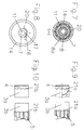
- the torque screwdriver consists of a blade whose shaft (1) has a non-circular profile cross-section - for example, a hexagonal profile cross-section - in a toothed sleeve (2) sits and until shortly before rear end is enough.
- the toothed sleeve (2) has on the circumference a substantially running over the length of toothing (2a), wherein the teeth preferably have a rectangular tooth profile.
- the two locking bushes (3a, 3b) serve with their cylindrical peripheral surface as a guide and for radial support of the mechanism described below in the cavity of the handle (14) which is closed by the cap (20).
- an internal toothing (3d Fig. 5) engage the locking bushes in the toothing (2 a) of the profile sleeve (2).
- the locking bushes On one end face, have a toothing (21) which has a wave-shaped or rounded at the tips tooth profile.
- the toothing (21) engages in a corresponding toothing of Mit videbüchsen (4, 5) of the first and second clutch.
- the Mit videbüchse (4) has on the toothing (21) opposite end side a rectangular spur toothing (4a) which engages in a uniform toothing in the handle (14) without play.
- the adjusting disc (6) is provided at the obliquely rising annular surface (12) opposite end face with a fine toothing (6a) and has on this page also a pin (7) in the holes in the locking disc (8) and the cap (20) of the handle is guided.
- a hexagon socket (11) is formed in the example, in which a key for adjusting the adjusting disc (6) can engage.
- a locking disc (8) is arranged, which has on the outer circumference a rectangular toothing (8a) which engages in a uniform internal toothing in the handle (14).
- the adjusting disc (6) facing the end face of the locking disc (8) also has a fine toothing (6a) which engages in the uniform toothing of the adjusting disc (6).
- the driving bush (5) is moved axially along the rising annular surface (12) together with the locking bush (3b) and thereby changes the bias of the coil spring (9). If a torque is transmitted to the driver bushes (4, 5) via the handle (14) and its internal toothings (4a, 15), this torque is transmitted to the toothed sleeve (2) via the detent bushings (3a, 3b) the shaft (1) forwarded.
- the bias of the coil spring (9) determines up to which torque the teeth (21) of the locking bushes (3a, 3b) and driving bushings (4, 5) remain in engagement before by rotating against each other, the transmission of the torque to the shaft (1 ) interrupt.
- 11 shows a longitudinal section through the screwing tool, in which the rear coupling parts (3b, 5) are displaced further forward by turning the adjusting disc (6) and the spring (9) is thereby pressed together and more strongly pretensioned. It can be seen here between the adjusting disc (6), or their lower portion of the obliquely rising annular surface (12) and the driving bush (5) resulting gap.
- the adjustable torque range can be determined and displayed on a scale (16, 17) at the end of the handle.
- the compression spring (9), or their spring characteristic the desired torque range can be set. It is also possible to cover with a screwdriver various torque ranges by the cap (20) unscrewed from the handle (14), the spring (9) replaced by a spring with a different characteristic and then the mechanism, cap and handle are reinstalled , As shown in Fig. 2, the adjusting disc (6) continues to serve as a bearing for the end portion (10) of the toothed sleeve (2), in particular as an axial bearing.
- FIG. 3 shows a cross section, along the line AA in FIG. 1, only through the region of the clamping device (18, 19) in the embodiment in which the shaft is replaceably inserted into the toothed sleeve.
- the clamping device (18) is formed integrally with the toothed sleeve as a cylindrical projection and has a spring tongue or a spring saddle (19) which projects inwardly into the cavity in the toothed sleeve and is resiliently deflected radially when inserting the shaft into the cavity , The spring tension of the deflected tongue or saddle holds the shaft in its axial position.
- the clamping device (18) can also be arranged between the two clutches, covered by the spring (9).
- the profile of the toothed sleeve (2) is not carried out in the region of the clamping device, the toothed sleeve slightly increased in diameter at this point.
- An alternative embodiment of the clamping device may consist of a band-ring spring and a ball, wherein the ball is seated in a radial bore in the toothed sleeve, something in the cavity (2b) protrudes the toothed sleeve and is attacked from the outside by the spring force of the band ring spring. If a shaft (1) is inserted into the cavity, the ball is radially outwardly displaced and the band-ring spring acts with a clamping force on the shaft.
- Fig. 4 the section B-B can be seen:
- Fig. 5 the section C-C, it can be seen how the locking bush (3b) with her cylindrical peripheral surface in the cavity of the handle (14) rotatably mounted and supported - as well as the locking bushing (3a) - and a Internal toothing (3d) connected to the external toothing (2a) of the toothed sleeve (2) is.
- Fig. 7 shows how the locking disc (8) on the external toothing (8a) is non-rotatably connected to the handle (14) and the pin (7) with the hexagon inner profile (11) rotatably mounted in the locking disc (8) is.
- the mark (16) on the pin (7) and the scale (17) on the cap (20) is shown as a principle.
- the screwing tool is expediently let into the cap a dial or be attached in another way, where the adjustable torque range is displayed directly. As stated above, it depends on the spring characteristic of the inserted spring (9) and is determined by calibration.
- the construction of adjusting disc (6) and driving sleeve (5) - with the inclined rising annular surfaces (12) allows a very accurate calibration.
- the increase angle of the annular surface (12) on the driver sleeve (5) and adjusting disc (6) determines the extent to which the transmittable torque changes at a certain displacement angle of the adjusting disc (6).
- the driver sleeve (5) and locking bushing (3b) are displaced only by a small distance and thus the spring (9) changed by this distance in length at a certain adjustment angle, correspondingly low is the change in the spring bias and the transmittable torque.
- Figures 9 and 10 show the couplings with different designs (21a, 21b) of the tooth forms. Due to the tooth shape, the torque range also be influenced. Is the flank angle ( ⁇ ) related on the axis of rotation of the clutch, large, so the teeth are smaller Torque slip past each other as if the angle ⁇ is small. Is the Flank angle 0 °, as in Fig. 10 in the direction of rotation to the left, so releases the clutch in this direction no longer off. In addition, at lower Loosening resistance of the screw, a reverse rotation of the screw avoided.
- Figures 11 and 12 show a more accurate form of the subsequent wave-shaped Tooth profiles of the toothing (21) shown in Figures 1, 2, 9, 10th and 11 is shown only in principle.
- the arrangement of two clutches and the other construction design according to the invention make it possible to transmit higher torques than if only one clutch were present, because the specific load of the components is lower, in particular the engaged form elements.
- the torque to be transmitted from the handle to the shaft is introduced into the transmission device at two points, namely via the front toothing (4a) of the driving bush (4) and via the toothing (5a) of the driving bush (5) or the internal toothing (15) of the handle (14).
- the burden of a transmission point for the torque or a clutch thus halved compared to such a device with only one clutch. It is therefore possible, all components except for the shaft (1), the spring (9) and the discs (13) made of plastic of suitable types by injection molding.
- Polyamide (PA) and polyoxymethylene (POM) have been found to be suitable types of plastic, especially as mating in those parts which interact in a sliding manner.
- a pairing was found to be particularly advantageous in which POM is compounded with Teflon.
- the friction of the mutually sliding surfaces is additionally reduced, in particular on the toothing (21) of latching and driving bush.
- influences of the friction are again reduced to the tripping torque and further increases the accuracy of the device.
- screwing tools with a preselected torque limiting device are also used in orthopedic surgery and it is necessary to sterilize them after use. Dry air sterilizers reach a temperature of 180 ° C. At this temperature, no permanent change in shape should occur on the parts of the screwing tool.
- the screwing tool is therefore made of plastics whose dimensional stability is still guaranteed up to a temperature of about 220 ° C.
- Parts such as the toothed sleeve (2) the latching bushes (3a, 3b) the Mitauerbüchsen (4, 5) the adjusting disc (6) the locking disc (8) or individual of these parts may alternatively be made of metal, for example as sintered parts in one Metal composition and / or metal mating, the good sliding properties, which are against each other, or even made of steel, stretched or formed by pressing.
- the handle (14) and the cap (20) may be made of metal about die-cast aluminum, and have a surface finished by anodization.
- the handle, cap and other, in particular statically loaded part may be made of stainless steel, such as wax-melting or powdered metal in the injection molding sintering process.
- the metal version is considered, if with the same dimensions as in the plastic version higher torques to be transmitted or, when used in orthopedic surgery, an unrestricted sterilization should be given. Since in an embodiment of the handle made of metal for weight reduction she wall thickness of sufficient durability is designed less on the requirements for a good feel, is provided in a variant of the main body of the handle, which has a non-circular outer contour in cross-section, a grip sleeve preferably elastic plastic, whose outer shape is designed according to ergonomic requirements.
- This grip sleeve is removed after use from the body and disposed of, especially if it is made of a resilient, less temperature-resistant plastic and can not be sterilized.
- This embodiment variant is shown by way of example in FIG. 13. In it are (14) the handle made of metal, (22) the grip sleeve made of elastic plastic.
- the setting device for the data to be transmitted is also advantageous Torque.
- the interaction of the obliquely rising ring surfaces (12) and the fine toothing (6a) on the locking disc (8) and on the adjusting disc (6) allow small adjustment steps, thus a precise adjustment the bias of the spring (9) and thus the tripping torque.
- the bias of the spring holds the locking disc in the set Location firm.
- the biasing force of the spring (9) is evenly distributed to both clutches, and on the one hand via the Mitauerbüchse (4 ), on the other side via the adjusting disc (6) and locking disc (8) in the handle (14) or the cap (20) derived, the tensioning force does not act with axial load on the toothed sleeve and the axial bearing.
Applications Claiming Priority (2)
| Application Number | Priority Date | Filing Date | Title |
|---|---|---|---|
| DE10341697 | 2003-09-10 | ||
| DE10341697A DE10341697B3 (de) | 2003-09-10 | 2003-09-10 | Schraubwerkzeug mit einer Vorrichtung zur Begrenzung des übertragenen Drehmomentes |
Publications (2)
| Publication Number | Publication Date |
|---|---|
| EP1514645A1 true EP1514645A1 (fr) | 2005-03-16 |
| EP1514645B1 EP1514645B1 (fr) | 2006-06-28 |
Family
ID=32946504
Family Applications (1)
| Application Number | Title | Priority Date | Filing Date |
|---|---|---|---|
| EP04011866A Active EP1514645B1 (fr) | 2003-09-10 | 2004-05-19 | Tournevis avec embrayage limitateur de couple |
Country Status (8)
| Country | Link |
|---|---|
| US (1) | US7197968B2 (fr) |
| EP (1) | EP1514645B1 (fr) |
| JP (1) | JP4478152B2 (fr) |
| CN (1) | CN100417496C (fr) |
| AT (1) | ATE331592T1 (fr) |
| DE (2) | DE10341697B3 (fr) |
| ES (1) | ES2268537T3 (fr) |
| WO (1) | WO2005023493A2 (fr) |
Cited By (3)
| Publication number | Priority date | Publication date | Assignee | Title |
|---|---|---|---|---|
| EP2594367A1 (fr) | 2011-11-07 | 2013-05-22 | PB Swiss Tools GmbH | Outil de vissage doté d'un dispositif de limitation du couple transmis |
| CN105232124A (zh) * | 2015-10-13 | 2016-01-13 | 广州聚生生物科技有限公司 | 一种徒手置钉外固定系统 |
| CN106470629A (zh) * | 2014-06-30 | 2017-03-01 | 德普伊新特斯产品公司 | 螺丝刀 |
Families Citing this family (96)
| Publication number | Priority date | Publication date | Assignee | Title |
|---|---|---|---|---|
| US7127955B2 (en) * | 2004-03-12 | 2006-10-31 | Bondhus Corporation | Torque limiting handle |
| US7272998B1 (en) * | 2004-06-16 | 2007-09-25 | Gauthier Michael T | Torque-limiting mechanism |
| TW200626309A (en) * | 2005-01-26 | 2006-08-01 | Chang-Chuan Lee | Torque screwdriver |
| US20070006692A1 (en) | 2005-07-11 | 2007-01-11 | Phan Christopher U | Torque limiting device |
| US8021366B2 (en) | 2005-07-11 | 2011-09-20 | Kyphon Sarl | Axial load limiting system and methods |
| JP4905647B2 (ja) * | 2006-02-14 | 2012-03-28 | 朝日インテック株式会社 | 医療用具 |
| US8105003B2 (en) * | 2006-09-08 | 2012-01-31 | Cardiac Pacemakers, Inc. | Method and apparatus for a fastener and a fastener cover including a sealable opening |
| ITVE20060075A1 (it) * | 2006-11-30 | 2008-06-01 | Silca Spa | Morsetto perfezionato di macchina per la cifratura di chiavi.- |
| US8814880B2 (en) * | 2006-12-28 | 2014-08-26 | Craig M. McAllister | Device and method for mounting an object on a bone |
| CN100509297C (zh) * | 2007-03-20 | 2009-07-08 | 力帆实业(集团)股份有限公司 | 一种扭力器 |
| WO2009023723A2 (fr) * | 2007-08-13 | 2009-02-19 | Thompson Cary A | Fixations de ski |
| US7793560B2 (en) * | 2007-09-11 | 2010-09-14 | Black & Decker Inc. | Transmission and variable radially expanding spring clutch assembly |
| WO2009134346A2 (fr) * | 2008-04-28 | 2009-11-05 | David Bryan Robinson | Procédés et appareil pour traverser des occlusions dans des vaisseaux sanguins |
| US7762164B2 (en) * | 2008-06-02 | 2010-07-27 | Eca Medical Instruments | Torque-limiting device |
| US8109183B2 (en) * | 2008-06-06 | 2012-02-07 | Black & Decker Inc. | Impact resistant tool bit and tool bit holder |
| EP2140978B1 (fr) * | 2008-07-01 | 2012-11-28 | Metabowerke GmbH | Vis autotaraudeuse à frapper |
| US8028608B2 (en) * | 2009-04-07 | 2011-10-04 | Depuy Products, Inc. | Torque-limiting fastener driver |
| US8430868B2 (en) * | 2009-04-23 | 2013-04-30 | Cardiac Pacemakers, Inc. | Axial-force limiting torque wrench for use with implantable medical devices |
| US8051751B2 (en) * | 2009-07-17 | 2011-11-08 | Hern Juei Co., Ltd. | Lockable torque-limiting driver |
| US8540580B2 (en) | 2009-08-12 | 2013-09-24 | Black & Decker Inc. | Tool bit or tool holder for power tool |
| FR2954689B1 (fr) * | 2009-12-28 | 2012-12-21 | Sterispine | Dispositif et methode pour la chirurgie rachidienne. |
| US8486116B2 (en) * | 2010-01-08 | 2013-07-16 | Biomet Manufacturing Ring Corporation | Variable angle locking screw |
| US9431868B2 (en) * | 2010-01-19 | 2016-08-30 | Tolomatic, Inc. | Manual override device for an electric actuator and method for use |
| US8141463B2 (en) * | 2010-01-28 | 2012-03-27 | Jin-Tsai Lai | Hand tool for adjusting torsion |
| US9132536B2 (en) | 2010-05-06 | 2015-09-15 | Eca Medical Instruments | Cannulated ultra high torque device |
| EP2566411B1 (fr) | 2010-05-06 | 2019-12-04 | ECA Medical Instruments | Dispositif à couple ultra-haut |
| US8365641B2 (en) * | 2010-05-12 | 2013-02-05 | Terry Daglow | Torque wrench |
| US20120059385A1 (en) | 2010-07-07 | 2012-03-08 | Orthohelix Surgical Designs, Inc. | Variable angle depth limited fastener driver and variable angle fixation system for use in orthopedic plates |
| US9162350B2 (en) | 2010-07-28 | 2015-10-20 | Eca Medical Instruments | Robust nose torque-limiting device |
| US9241751B2 (en) * | 2010-07-28 | 2016-01-26 | Eca Medical Instruments | Cannulated torque device and tip engagement |
| US8408104B2 (en) * | 2010-11-03 | 2013-04-02 | Yih Cheng Factory Co., Ltd. | Screwdriver for exerting an adjustable maximum value of torque |
| US8728129B2 (en) | 2011-01-07 | 2014-05-20 | Biomet Manufacturing, Llc | Variable angled locking screw |
| US9242357B2 (en) | 2011-02-19 | 2016-01-26 | Eca Medical Instruments | Enhanced high torque device |
| CN102078216B (zh) * | 2011-03-07 | 2012-03-14 | 宋艳芹 | 手术用骨螺钉改锥 |
| CN102078215B (zh) * | 2011-03-07 | 2012-03-14 | 鞠传宝 | 骨螺钉专用改锥 |
| TW201240776A (en) * | 2011-04-14 | 2012-10-16 | Zhen-Chang Cai | Torque screwdriver |
| TWI396608B (zh) * | 2011-06-03 | 2013-05-21 | Kabo Tool Co | 電子式扭力螺絲起子 |
| TWI457209B (zh) * | 2012-07-09 | 2014-10-21 | Kabo Tool Co | Hand tools of the torque body |
| WO2014035496A1 (fr) | 2012-08-30 | 2014-03-06 | Eca Medical Instruments | Base destinée à un dispositif sélectionnable, jetable, de limitation de couples de torsion |
| US9016175B2 (en) * | 2012-09-05 | 2015-04-28 | Matatakitoyo Tool Co., Ltd. | Clutch for torque-exerting device |
| US8973475B2 (en) * | 2012-10-19 | 2015-03-10 | Jin Tsai LAI | Torsion adjusting structure of a screwdriver |
| CA2899036C (fr) * | 2013-01-23 | 2021-02-16 | Eca Medical Instruments | Dispositifs de couple jetables en plastique renforces |
| US20150082937A1 (en) | 2013-03-15 | 2015-03-26 | Guardair Corp. | Locking handle |
| TWI495546B (en) * | 2013-05-15 | 2015-08-11 | Torque adjustment device for screwdriver | |
| TWI537106B (zh) * | 2013-05-20 | 2016-06-11 | Kabo Tool Co | Torque wrenches for torque correction and their torque correction methods |
| US9555526B1 (en) | 2013-06-28 | 2017-01-31 | Gauthier Biomedical, Inc. | Selectively lockable torque-limiting mechanism |
| GB2521205A (en) * | 2013-12-13 | 2015-06-17 | Ching-Shu Huang | Tool driver |
| ITMI20140074U1 (it) * | 2014-02-26 | 2015-08-26 | Elesa Spa | Impugnatura perfezionata. |
| IL231928A0 (en) * | 2014-04-03 | 2014-08-31 | Mis Implants Technologies Ltd | Rotatable tightening device with integral torque limiter |
| DE102014109200A1 (de) * | 2014-07-01 | 2016-01-07 | Aesculap Ag | Medizinischer Schraubendreher, Schaft für den medizinischen Schraubendreher und Verfahren zum Einbringen von Pedikelschrauben |
| CN104161583B (zh) * | 2014-08-18 | 2016-04-13 | 东莞乐域光电科技有限公司 | 一种具有计数及自毁功能的医用扭力工具 |
| WO2016027176A1 (fr) * | 2014-08-20 | 2016-02-25 | Tecres S.P.A. | Poignée d'application de couple et unité de distribution équipée d'une telle poignée |
| CN105459004B (zh) * | 2014-09-11 | 2017-07-04 | 瞬丰实业有限公司 | 扭矩调节装置及一种具有此扭矩调节装置的工具 |
| KR101635613B1 (ko) * | 2014-11-27 | 2016-07-04 | 임영철 | 열박음 공구척 |
| DE102015102771A1 (de) * | 2015-02-26 | 2016-09-01 | Paul Hettich Gmbh & Co. Kg | Schubkasten und Blendenträger für eine Frontblende eines Schubkastens |
| EP3087935B1 (fr) | 2015-04-17 | 2019-05-22 | Greatbatch Ltd. | Limiteur de couple à deux étages |
| EP3097886B1 (fr) | 2015-05-29 | 2019-11-13 | Greatbatch Ltd. | Limiteur de couple à mécanisme de forme lobée |
| US10279146B2 (en) | 2015-06-02 | 2019-05-07 | Eca Medical Instruments | Cannulated disposable torque limiting device with plastic shaft |
| TWI614094B (zh) * | 2015-06-16 | 2018-02-11 | Mijy Land Industrial Co Ltd | 可調整動態負載精度之自動起子 |
| CN105105839B (zh) * | 2015-09-22 | 2017-08-01 | 杭州承诺医疗科技有限公司 | 一种医用扭力螺丝刀 |
| US10343269B2 (en) | 2015-10-07 | 2019-07-09 | Eca Medical Instruments | Hypocycloid reduction gearless spring washer torque limiting device |
| EP3359839B1 (fr) | 2015-10-07 | 2021-06-02 | ECA Medical Instruments | Entraînement de couple compact sans engrenage |
| EP3359341B1 (fr) | 2015-10-07 | 2020-12-16 | ECA Medical Instruments | Dispositif à couple élevé à rondelle à ressort sans engrenage |
| WO2017062068A1 (fr) * | 2015-10-07 | 2017-04-13 | Eca Medical Instruments | Entraînement à couple sans engrenage |
| US11203102B2 (en) | 2015-10-07 | 2021-12-21 | Eca Medical Instruments | Gearless in-line torque limited device |
| CN105500292B (zh) * | 2016-01-12 | 2017-07-21 | 浙江工业职业技术学院 | 多功能扭力套装工具 |
| CN105710817A (zh) * | 2016-04-27 | 2016-06-29 | 厦门南旗佰特精密工具制造有限公司 | 精密电动螺丝刀 |
| CN105773505A (zh) * | 2016-04-27 | 2016-07-20 | 厦门南旗佰特精密工具制造有限公司 | 螺丝刀扭力调节装置 |
| DE102016113355A1 (de) * | 2016-07-20 | 2018-01-25 | B. Braun Melsungen Ag | Medizintechnische Klemmvorrichtung mit Rutschkupplung |
| EP3507523B1 (fr) | 2016-08-30 | 2023-05-10 | ECA Medical Instruments | Tampon de vitesse hypocycloïde |
| DE102016122442A1 (de) * | 2016-11-22 | 2018-05-24 | Audi Ag | Pressvorrichtung zum Pressen eines Brennstoffzellenstapels und Brennstoffzellenvorrichtung mit Pressvorrichtung |
| FI127464B (fi) * | 2017-02-17 | 2018-06-29 | Innotia Eesti Oue | Mekaaninen suojakytkin |
| JP6763574B2 (ja) * | 2017-02-23 | 2020-09-30 | Tone株式会社 | トルクドライバー |
| CN106964822B (zh) * | 2017-05-15 | 2022-11-08 | 丹阳市剑庐工具有限公司 | 高扭柄旋具 |
| CN108071706A (zh) * | 2017-12-05 | 2018-05-25 | 王凯 | 一种基于离心块控制钢珠驱动的建筑使用的扭矩限制器 |
| US10856924B2 (en) * | 2017-12-21 | 2020-12-08 | Globus Medical Inc. | Headless compression screw driver system |
| DE102018100832A1 (de) * | 2018-01-16 | 2019-09-19 | Böllhoff Verbindungstechnik GmbH | Einbauwerkzeug für einen Drahtgewindeeinsatz |
| DE102018112068A1 (de) * | 2018-05-18 | 2019-11-21 | Wera Werkzeuge Gmbh | Schraubwerkzeug zur Übertragung zwei fest eingestellter Drehmomente |
| WO2019238932A1 (fr) * | 2018-06-15 | 2019-12-19 | Wera Werkzeuge Gmbh | Dispositif limiteur de couple et son procédé d'étalonnage |
| WO2020125677A1 (fr) * | 2018-12-18 | 2020-06-25 | 天臣国际医疗科技股份有限公司 | Ensemble bouton rotatif et agrafeuse circulaire de type tube |
| US11441611B2 (en) * | 2019-02-27 | 2022-09-13 | Carefusion 303, Inc. | Torque limiting connector |
| US20220125489A1 (en) | 2019-03-26 | 2022-04-28 | Neo Medical Sa | System for Tightening an Orthopedic Set Screw at Two Different Torque Levels |
| AT522457B1 (de) * | 2019-05-17 | 2020-11-15 | Blum Gmbh Julius | Möbelbeschlag |
| CN110338880B (zh) * | 2019-07-18 | 2020-06-12 | 中国人民解放军东部战区总医院 | 用于关节软骨损伤的修复工装 |
| CN110575241A (zh) * | 2019-09-23 | 2019-12-17 | 河海大学常州校区 | 一种骨科取钉装置 |
| CN110584771A (zh) * | 2019-09-24 | 2019-12-20 | 西安交通大学医学院第二附属医院 | 一种骨科螺钉的松动与拆卸装置及基于其松动与拆除骨科螺钉的方法 |
| CN111643231A (zh) * | 2020-05-25 | 2020-09-11 | 天衍医疗器材有限公司 | 可调节扭力的万向棘轮改锥 |
| TWI749773B (zh) * | 2020-09-17 | 2021-12-11 | 超立榮實業有限公司 | 扭力扳手之扭力輸出機構 |
| US20220111502A1 (en) * | 2020-10-09 | 2022-04-14 | Milwaukee Electric Tool Corporation | Torque stick for a rotary impact tool |
| CN113059533B (zh) * | 2021-03-12 | 2023-07-25 | 河北工业职业技术学院 | 联动旋丝装置 |
| CN113447176B (zh) * | 2021-06-17 | 2022-04-01 | 人本股份有限公司 | 双半外圈轴承摩擦力矩检测装置 |
| TWI830102B (zh) * | 2021-12-15 | 2024-01-21 | 超立榮實業有限公司 | 扭力扳手之扭力輸出機構 |
| TWI782823B (zh) * | 2021-12-16 | 2022-11-01 | 特典工具股份有限公司 | 扭力工具 |
| US20230255645A1 (en) * | 2022-02-11 | 2023-08-17 | Arthrex, Inc. | Surgical impact driver adaptors for applying directed torque and linear impact loads during surgical procedures |
| CN114789420B (zh) * | 2022-05-31 | 2024-03-26 | 苏州浪潮智能科技有限公司 | 一种可调扭矩螺丝刀 |
| DE102022114689A1 (de) | 2022-06-10 | 2023-12-21 | Wera Werkzeuge Gmbh | Schraubwerkzeug mit Drehmomentbegrenzungseinrichtung |
Citations (5)
| Publication number | Priority date | Publication date | Assignee | Title |
|---|---|---|---|---|
| US2335574A (en) * | 1942-11-13 | 1943-11-30 | Thompson | Safety turning device for tightening bolts, screws, or the like |
| DE884780C (de) * | 1951-05-20 | 1953-07-30 | Karl Wilhelm Urbach | Einsatzstueck fuer Schraubenschluessel zum Ausueben bestimmter einstellbarer Drehmomente |
| DE2427352A1 (de) * | 1974-06-06 | 1975-12-18 | Ulrich Schmidt | Vorsatzschraubendreher |
| DE2647996A1 (de) * | 1975-11-06 | 1977-05-12 | Dresser Ind | Schraubenzieher mit drehmomentbegrenzung |
| EP1092510A2 (fr) * | 1999-10-11 | 2001-04-18 | Kapman AB | Tournevis dynamométrique |
Family Cites Families (11)
| Publication number | Priority date | Publication date | Assignee | Title |
|---|---|---|---|---|
| US2410971A (en) * | 1943-12-10 | 1946-11-12 | Parker Appliance Co | Screw driver |
| US2396040A (en) * | 1944-10-30 | 1946-03-05 | Frank L Darling | Screw driver |
| US2884103A (en) * | 1954-04-08 | 1959-04-28 | Chicago Pneumatic Tool Co | Predetermined torque release mechanism |
| US2797564A (en) * | 1954-08-11 | 1957-07-02 | Joseph C Bonneau | Adjustable torque tool |
| US2771804A (en) * | 1955-05-09 | 1956-11-27 | Scully Jones & Co | Predetermined torque release wrench |
| DE2447352A1 (de) | 1974-10-04 | 1976-04-15 | Teves Gmbh Alfred | Hydraulische bremsanlage mit einem druckspeicher |
| CN2082663U (zh) * | 1990-06-11 | 1991-08-14 | 杨其昌 | 可调定力组合螺丝起子 |
| CN2183856Y (zh) * | 1994-03-10 | 1994-11-30 | 邵琦 | 具有扭矩控制的紧固工具 |
| CN2239329Y (zh) * | 1995-10-25 | 1996-11-06 | 许忠庆 | 微调扭力扳手 |
| US5746298A (en) * | 1996-07-19 | 1998-05-05 | Snap-On Technologies, Inc. | Adjustable torque-limiting mini screwdriver |
| DE10143181B4 (de) * | 2001-09-04 | 2005-03-03 | Willi Hahn Gmbh & Co. Kg | Vorrichtung zur Begrenzung des von einem Schraubwerkzeug übertragbaren Drehmoments |
-
2003
- 2003-09-10 DE DE10341697A patent/DE10341697B3/de not_active Expired - Fee Related
-
2004
- 2004-05-19 DE DE502004000869T patent/DE502004000869D1/de active Active
- 2004-05-19 ES ES04011866T patent/ES2268537T3/es active Active
- 2004-05-19 AT AT04011866T patent/ATE331592T1/de not_active IP Right Cessation
- 2004-05-19 EP EP04011866A patent/EP1514645B1/fr active Active
- 2004-09-08 JP JP2006525923A patent/JP4478152B2/ja active Active
- 2004-09-08 CN CNB2004800260874A patent/CN100417496C/zh active Active
- 2004-09-08 WO PCT/IB2004/002917 patent/WO2005023493A2/fr active Application Filing
-
2005
- 2005-05-10 US US11/126,087 patent/US7197968B2/en active Active
Patent Citations (5)
| Publication number | Priority date | Publication date | Assignee | Title |
|---|---|---|---|---|
| US2335574A (en) * | 1942-11-13 | 1943-11-30 | Thompson | Safety turning device for tightening bolts, screws, or the like |
| DE884780C (de) * | 1951-05-20 | 1953-07-30 | Karl Wilhelm Urbach | Einsatzstueck fuer Schraubenschluessel zum Ausueben bestimmter einstellbarer Drehmomente |
| DE2427352A1 (de) * | 1974-06-06 | 1975-12-18 | Ulrich Schmidt | Vorsatzschraubendreher |
| DE2647996A1 (de) * | 1975-11-06 | 1977-05-12 | Dresser Ind | Schraubenzieher mit drehmomentbegrenzung |
| EP1092510A2 (fr) * | 1999-10-11 | 2001-04-18 | Kapman AB | Tournevis dynamométrique |
Cited By (4)
| Publication number | Priority date | Publication date | Assignee | Title |
|---|---|---|---|---|
| EP2594367A1 (fr) | 2011-11-07 | 2013-05-22 | PB Swiss Tools GmbH | Outil de vissage doté d'un dispositif de limitation du couple transmis |
| CN106470629A (zh) * | 2014-06-30 | 2017-03-01 | 德普伊新特斯产品公司 | 螺丝刀 |
| US10271888B2 (en) | 2014-06-30 | 2019-04-30 | DePuy Synthes Products, Inc. | Hex screwdriver handle |
| CN105232124A (zh) * | 2015-10-13 | 2016-01-13 | 广州聚生生物科技有限公司 | 一种徒手置钉外固定系统 |
Also Published As
| Publication number | Publication date |
|---|---|
| ES2268537T3 (es) | 2007-03-16 |
| DE502004000869D1 (de) | 2006-08-10 |
| JP4478152B2 (ja) | 2010-06-09 |
| EP1514645B1 (fr) | 2006-06-28 |
| DE10341697B3 (de) | 2004-10-07 |
| ATE331592T1 (de) | 2006-07-15 |
| CN1849200A (zh) | 2006-10-18 |
| CN100417496C (zh) | 2008-09-10 |
| WO2005023493A2 (fr) | 2005-03-17 |
| WO2005023493A3 (fr) | 2005-05-12 |
| US20060016300A1 (en) | 2006-01-26 |
| JP2007504960A (ja) | 2007-03-08 |
| US7197968B2 (en) | 2007-04-03 |
Similar Documents
| Publication | Publication Date | Title |
|---|---|---|
| EP1514645B1 (fr) | Tournevis avec embrayage limitateur de couple | |
| DE69921250T2 (de) | Automatische Spindel-Sperre | |
| EP0635658B1 (fr) | Transmission à trains épicycloidaux équipée d'un limitateur de couple et son application dans des outils à main | |
| DE102018100054B4 (de) | Verriegelbarer Drehmomentschlüssel mit einem Hinweiston | |
| EP2564960B1 (fr) | Mandrin pour un outil | |
| WO2003017857A1 (fr) | Dispositif permettant de limiter un couple a transmettre | |
| EP0577981B1 (fr) | Tête pour une pièce à main médicale ou dentaire comportant un outil de traitement oscillant | |
| EP2851155A2 (fr) | Mécanisme à rochet à denture fine | |
| EP1132173A2 (fr) | Outil de transmission de couple | |
| EP2594367B1 (fr) | Outil de vissage doté d'un dispositif de limitation du couple transmis | |
| DE10161356B4 (de) | Schraubgerät | |
| DE10030114A1 (de) | Handstück für medizinische Zwecke, insbesondere für eine ärztliche oder zahnärztliche Behandlungseinrichtung, vorzugsweise für eine spanabhebende Bearbeitung eines Zahn-Wurzelkanals | |
| EP0239670A2 (fr) | Machine motorisée avec réglage du couple, en particulier outillages électriques | |
| AT412643B (de) | Hubeinrichtung | |
| EP0925762B1 (fr) | Outil pour une pièce à main contre-angle ou droite avec dispositif de serrage détachable pour l'outil, en particulier pour des fins médicales | |
| DE4102014C2 (de) | Handgeführte Elektrowerkzeugmaschine mit Überlastkupplung | |
| DE10143181B4 (de) | Vorrichtung zur Begrenzung des von einem Schraubwerkzeug übertragbaren Drehmoments | |
| DE102004061482B4 (de) | Schraubwerkzeug mit einstellbarer Drehmomentbegrenzungseinrichtung | |
| DE20314486U1 (de) | Schraubwerkzeug mit einer Vorrichtung zur Begrenzung des übertragenen Drehmomentes | |
| DE202008001334U1 (de) | Schraubenschlüssel | |
| DE4425961A1 (de) | Planetengetriebe und dessen Verwendung | |
| DE10346456A1 (de) | Knarre für medizinische und zahnmedizinische Zwecke | |
| DE102004007372B4 (de) | Schraubwerkzeug | |
| DE202014001166U1 (de) | Handwerkzeug mit einer Drehzahl-Anzeigefunktion | |
| DE2502600C3 (de) | Vorrichtung zum Verändern der Spurweite, insbesondere von landwirtschaftlichen Fahrzeugen |
Legal Events
| Date | Code | Title | Description |
|---|---|---|---|
| PUAI | Public reference made under article 153(3) epc to a published international application that has entered the european phase |
Free format text: ORIGINAL CODE: 0009012 |
|
| AK | Designated contracting states |
Kind code of ref document: A1 Designated state(s): AT BE BG CH CY CZ DE DK EE ES FI FR GB GR HU IE IT LI LU MC NL PL PT RO SE SI SK TR |
|
| AX | Request for extension of the european patent |
Extension state: AL HR LT LV MK |
|
| 17P | Request for examination filed |
Effective date: 20050315 |
|
| 17Q | First examination report despatched |
Effective date: 20050530 |
|
| GRAP | Despatch of communication of intention to grant a patent |
Free format text: ORIGINAL CODE: EPIDOSNIGR1 |
|
| GRAS | Grant fee paid |
Free format text: ORIGINAL CODE: EPIDOSNIGR3 |
|
| AKX | Designation fees paid |
Designated state(s): AT BE BG CH CY CZ DE DK EE ES FI FR GB GR HU IE IT LI LU MC NL PL PT RO SE SI SK TR |
|
| GRAA | (expected) grant |
Free format text: ORIGINAL CODE: 0009210 |
|
| AK | Designated contracting states |
Kind code of ref document: B1 Designated state(s): AT BE BG CH CY CZ DE DK EE ES FI FR GB GR HU IE IT LI LU MC NL PL PT RO SE SI SK TR |
|
| PG25 | Lapsed in a contracting state [announced via postgrant information from national office to epo] |
Ref country code: IT Free format text: LAPSE BECAUSE OF FAILURE TO SUBMIT A TRANSLATION OF THE DESCRIPTION OR TO PAY THE FEE WITHIN THE PRESCRIBED TIME-LIMIT;WARNING: LAPSES OF ITALIAN PATENTS WITH EFFECTIVE DATE BEFORE 2007 MAY HAVE OCCURRED AT ANY TIME BEFORE 2007. THE CORRECT EFFECTIVE DATE MAY BE DIFFERENT FROM THE ONE RECORDED. Effective date: 20060628 Ref country code: SK Free format text: LAPSE BECAUSE OF FAILURE TO SUBMIT A TRANSLATION OF THE DESCRIPTION OR TO PAY THE FEE WITHIN THE PRESCRIBED TIME-LIMIT Effective date: 20060628 Ref country code: NL Free format text: LAPSE BECAUSE OF FAILURE TO SUBMIT A TRANSLATION OF THE DESCRIPTION OR TO PAY THE FEE WITHIN THE PRESCRIBED TIME-LIMIT Effective date: 20060628 Ref country code: FI Free format text: LAPSE BECAUSE OF FAILURE TO SUBMIT A TRANSLATION OF THE DESCRIPTION OR TO PAY THE FEE WITHIN THE PRESCRIBED TIME-LIMIT Effective date: 20060628 Ref country code: IE Free format text: LAPSE BECAUSE OF FAILURE TO SUBMIT A TRANSLATION OF THE DESCRIPTION OR TO PAY THE FEE WITHIN THE PRESCRIBED TIME-LIMIT Effective date: 20060628 Ref country code: PL Free format text: LAPSE BECAUSE OF FAILURE TO SUBMIT A TRANSLATION OF THE DESCRIPTION OR TO PAY THE FEE WITHIN THE PRESCRIBED TIME-LIMIT Effective date: 20060628 Ref country code: SI Free format text: LAPSE BECAUSE OF FAILURE TO SUBMIT A TRANSLATION OF THE DESCRIPTION OR TO PAY THE FEE WITHIN THE PRESCRIBED TIME-LIMIT Effective date: 20060628 Ref country code: RO Free format text: LAPSE BECAUSE OF FAILURE TO SUBMIT A TRANSLATION OF THE DESCRIPTION OR TO PAY THE FEE WITHIN THE PRESCRIBED TIME-LIMIT Effective date: 20060628 Ref country code: CZ Free format text: LAPSE BECAUSE OF FAILURE TO SUBMIT A TRANSLATION OF THE DESCRIPTION OR TO PAY THE FEE WITHIN THE PRESCRIBED TIME-LIMIT Effective date: 20060628 |
|
| REG | Reference to a national code |
Ref country code: GB Ref legal event code: FG4D Free format text: NOT ENGLISH |
|
| REG | Reference to a national code |
Ref country code: CH Ref legal event code: EP |
|
| REG | Reference to a national code |
Ref country code: IE Ref legal event code: FG4D Free format text: LANGUAGE OF EP DOCUMENT: GERMAN |
|
| REF | Corresponds to: |
Ref document number: 502004000869 Country of ref document: DE Date of ref document: 20060810 Kind code of ref document: P |
|
| PG25 | Lapsed in a contracting state [announced via postgrant information from national office to epo] |
Ref country code: DK Free format text: LAPSE BECAUSE OF FAILURE TO SUBMIT A TRANSLATION OF THE DESCRIPTION OR TO PAY THE FEE WITHIN THE PRESCRIBED TIME-LIMIT Effective date: 20060928 Ref country code: SE Free format text: LAPSE BECAUSE OF FAILURE TO SUBMIT A TRANSLATION OF THE DESCRIPTION OR TO PAY THE FEE WITHIN THE PRESCRIBED TIME-LIMIT Effective date: 20060928 |
|
| GBT | Gb: translation of ep patent filed (gb section 77(6)(a)/1977) |
Effective date: 20061004 |
|
| PG25 | Lapsed in a contracting state [announced via postgrant information from national office to epo] |
Ref country code: PT Free format text: LAPSE BECAUSE OF FAILURE TO SUBMIT A TRANSLATION OF THE DESCRIPTION OR TO PAY THE FEE WITHIN THE PRESCRIBED TIME-LIMIT Effective date: 20061128 |
|
| NLV1 | Nl: lapsed or annulled due to failure to fulfill the requirements of art. 29p and 29m of the patents act | ||
| REG | Reference to a national code |
Ref country code: IE Ref legal event code: FD4D |
|
| REG | Reference to a national code |
Ref country code: ES Ref legal event code: FG2A Ref document number: 2268537 Country of ref document: ES Kind code of ref document: T3 |
|
| PLBE | No opposition filed within time limit |
Free format text: ORIGINAL CODE: 0009261 |
|
| STAA | Information on the status of an ep patent application or granted ep patent |
Free format text: STATUS: NO OPPOSITION FILED WITHIN TIME LIMIT |
|
| EN | Fr: translation not filed | ||
| 26N | No opposition filed |
Effective date: 20070329 |
|
| BERE | Be: lapsed |
Owner name: FELO-WERKZEUGFABRIK HOLLAND-LETZ G.M.B.H. Effective date: 20070531 |
|
| PG25 | Lapsed in a contracting state [announced via postgrant information from national office to epo] |
Ref country code: MC Free format text: LAPSE BECAUSE OF NON-PAYMENT OF DUE FEES Effective date: 20070531 |
|
| PG25 | Lapsed in a contracting state [announced via postgrant information from national office to epo] |
Ref country code: BE Free format text: LAPSE BECAUSE OF NON-PAYMENT OF DUE FEES Effective date: 20070531 |
|
| PG25 | Lapsed in a contracting state [announced via postgrant information from national office to epo] |
Ref country code: GR Free format text: LAPSE BECAUSE OF FAILURE TO SUBMIT A TRANSLATION OF THE DESCRIPTION OR TO PAY THE FEE WITHIN THE PRESCRIBED TIME-LIMIT Effective date: 20060929 Ref country code: FR Free format text: LAPSE BECAUSE OF FAILURE TO SUBMIT A TRANSLATION OF THE DESCRIPTION OR TO PAY THE FEE WITHIN THE PRESCRIBED TIME-LIMIT Effective date: 20070511 |
|
| PG25 | Lapsed in a contracting state [announced via postgrant information from national office to epo] |
Ref country code: BG Free format text: LAPSE BECAUSE OF FAILURE TO SUBMIT A TRANSLATION OF THE DESCRIPTION OR TO PAY THE FEE WITHIN THE PRESCRIBED TIME-LIMIT Effective date: 20060928 |
|
| PG25 | Lapsed in a contracting state [announced via postgrant information from national office to epo] |
Ref country code: EE Free format text: LAPSE BECAUSE OF FAILURE TO SUBMIT A TRANSLATION OF THE DESCRIPTION OR TO PAY THE FEE WITHIN THE PRESCRIBED TIME-LIMIT Effective date: 20060628 |
|
| PG25 | Lapsed in a contracting state [announced via postgrant information from national office to epo] |
Ref country code: AT Free format text: LAPSE BECAUSE OF NON-PAYMENT OF DUE FEES Effective date: 20070519 |
|
| PGRI | Patent reinstated in contracting state [announced from national office to epo] |
Ref country code: IT Effective date: 20080801 |
|
| PG25 | Lapsed in a contracting state [announced via postgrant information from national office to epo] |
Ref country code: FR Free format text: LAPSE BECAUSE OF FAILURE TO SUBMIT A TRANSLATION OF THE DESCRIPTION OR TO PAY THE FEE WITHIN THE PRESCRIBED TIME-LIMIT Effective date: 20060628 |
|
| REG | Reference to a national code |
Ref country code: CH Ref legal event code: PL |
|
| PG25 | Lapsed in a contracting state [announced via postgrant information from national office to epo] |
Ref country code: LI Free format text: LAPSE BECAUSE OF NON-PAYMENT OF DUE FEES Effective date: 20080531 Ref country code: CH Free format text: LAPSE BECAUSE OF NON-PAYMENT OF DUE FEES Effective date: 20080531 |
|
| PG25 | Lapsed in a contracting state [announced via postgrant information from national office to epo] |
Ref country code: CY Free format text: LAPSE BECAUSE OF FAILURE TO SUBMIT A TRANSLATION OF THE DESCRIPTION OR TO PAY THE FEE WITHIN THE PRESCRIBED TIME-LIMIT Effective date: 20060628 Ref country code: LU Free format text: LAPSE BECAUSE OF NON-PAYMENT OF DUE FEES Effective date: 20070519 |
|
| PG25 | Lapsed in a contracting state [announced via postgrant information from national office to epo] |
Ref country code: HU Free format text: LAPSE BECAUSE OF FAILURE TO SUBMIT A TRANSLATION OF THE DESCRIPTION OR TO PAY THE FEE WITHIN THE PRESCRIBED TIME-LIMIT Effective date: 20061229 Ref country code: TR Free format text: LAPSE BECAUSE OF FAILURE TO SUBMIT A TRANSLATION OF THE DESCRIPTION OR TO PAY THE FEE WITHIN THE PRESCRIBED TIME-LIMIT Effective date: 20060628 |
|
| PGFP | Annual fee paid to national office [announced via postgrant information from national office to epo] |
Ref country code: IT Payment date: 20230531 Year of fee payment: 20 Ref country code: ES Payment date: 20230621 Year of fee payment: 20 Ref country code: DE Payment date: 20230525 Year of fee payment: 20 |
|
| PGFP | Annual fee paid to national office [announced via postgrant information from national office to epo] |
Ref country code: GB Payment date: 20230522 Year of fee payment: 20 |