EP1514645A1 - Screwdriver with torque limiting clutch - Google Patents
Screwdriver with torque limiting clutch Download PDFInfo
- Publication number
- EP1514645A1 EP1514645A1 EP04011866A EP04011866A EP1514645A1 EP 1514645 A1 EP1514645 A1 EP 1514645A1 EP 04011866 A EP04011866 A EP 04011866A EP 04011866 A EP04011866 A EP 04011866A EP 1514645 A1 EP1514645 A1 EP 1514645A1
- Authority
- EP
- European Patent Office
- Prior art keywords
- limiting
- screwing tool
- torque according
- transmitted torque
- handle
- Prior art date
- Legal status (The legal status is an assumption and is not a legal conclusion. Google has not performed a legal analysis and makes no representation as to the accuracy of the status listed.)
- Granted
Links
Images


Classifications
-
- B—PERFORMING OPERATIONS; TRANSPORTING
- B25—HAND TOOLS; PORTABLE POWER-DRIVEN TOOLS; MANIPULATORS
- B25B—TOOLS OR BENCH DEVICES NOT OTHERWISE PROVIDED FOR, FOR FASTENING, CONNECTING, DISENGAGING OR HOLDING
- B25B23/00—Details of, or accessories for, spanners, wrenches, screwdrivers
- B25B23/14—Arrangement of torque limiters or torque indicators in wrenches or screwdrivers
- B25B23/142—Arrangement of torque limiters or torque indicators in wrenches or screwdrivers specially adapted for hand operated wrenches or screwdrivers
- B25B23/1422—Arrangement of torque limiters or torque indicators in wrenches or screwdrivers specially adapted for hand operated wrenches or screwdrivers torque indicators or adjustable torque limiters
- B25B23/1427—Arrangement of torque limiters or torque indicators in wrenches or screwdrivers specially adapted for hand operated wrenches or screwdrivers torque indicators or adjustable torque limiters by mechanical means
-
- A—HUMAN NECESSITIES
- A61—MEDICAL OR VETERINARY SCIENCE; HYGIENE
- A61B—DIAGNOSIS; SURGERY; IDENTIFICATION
- A61B17/00—Surgical instruments, devices or methods, e.g. tourniquets
- A61B17/56—Surgical instruments or methods for treatment of bones or joints; Devices specially adapted therefor
- A61B17/58—Surgical instruments or methods for treatment of bones or joints; Devices specially adapted therefor for osteosynthesis, e.g. bone plates, screws, setting implements or the like
- A61B17/88—Osteosynthesis instruments; Methods or means for implanting or extracting internal or external fixation devices
- A61B17/8875—Screwdrivers, spanners or wrenches
-
- B—PERFORMING OPERATIONS; TRANSPORTING
- B25—HAND TOOLS; PORTABLE POWER-DRIVEN TOOLS; MANIPULATORS
- B25B—TOOLS OR BENCH DEVICES NOT OTHERWISE PROVIDED FOR, FOR FASTENING, CONNECTING, DISENGAGING OR HOLDING
- B25B15/00—Screwdrivers
- B25B15/02—Screwdrivers operated by rotating the handle
-
- B—PERFORMING OPERATIONS; TRANSPORTING
- B25—HAND TOOLS; PORTABLE POWER-DRIVEN TOOLS; MANIPULATORS
- B25B—TOOLS OR BENCH DEVICES NOT OTHERWISE PROVIDED FOR, FOR FASTENING, CONNECTING, DISENGAGING OR HOLDING
- B25B23/00—Details of, or accessories for, spanners, wrenches, screwdrivers
- B25B23/0007—Connections or joints between tool parts
- B25B23/0042—Connection means between screwdriver handle and screwdriver shaft
-
- B—PERFORMING OPERATIONS; TRANSPORTING
- B25—HAND TOOLS; PORTABLE POWER-DRIVEN TOOLS; MANIPULATORS
- B25G—HANDLES FOR HAND IMPLEMENTS
- B25G1/00—Handle constructions
- B25G1/04—Handle constructions telescopic; extensible; sectional
- B25G1/043—Handle constructions telescopic; extensible; sectional for screwdrivers, wrenches or spanners
- B25G1/046—Handle constructions telescopic; extensible; sectional for screwdrivers, wrenches or spanners with free-turning section at end of handle remote from tool
-
- B—PERFORMING OPERATIONS; TRANSPORTING
- B25—HAND TOOLS; PORTABLE POWER-DRIVEN TOOLS; MANIPULATORS
- B25G—HANDLES FOR HAND IMPLEMENTS
- B25G1/00—Handle constructions
- B25G1/10—Handle constructions characterised by material or shape
- B25G1/12—Handle constructions characterised by material or shape electrically insulating material
- B25G1/125—Handle constructions characterised by material or shape electrically insulating material for screwdrivers, wrenches or spanners
-
- B—PERFORMING OPERATIONS; TRANSPORTING
- B25—HAND TOOLS; PORTABLE POWER-DRIVEN TOOLS; MANIPULATORS
- B25G—HANDLES FOR HAND IMPLEMENTS
- B25G3/00—Attaching handles to the implements
- B25G3/02—Socket, tang, or like fixings
- B25G3/12—Locking and securing devices
- B25G3/18—Locking and securing devices comprising catches or pawls
-
- A—HUMAN NECESSITIES
- A61—MEDICAL OR VETERINARY SCIENCE; HYGIENE
- A61B—DIAGNOSIS; SURGERY; IDENTIFICATION
- A61B17/00—Surgical instruments, devices or methods, e.g. tourniquets
- A61B2017/0046—Surgical instruments, devices or methods, e.g. tourniquets with a releasable handle; with handle and operating part separable
- A61B2017/00464—Surgical instruments, devices or methods, e.g. tourniquets with a releasable handle; with handle and operating part separable for use with different instruments
-
- A—HUMAN NECESSITIES
- A61—MEDICAL OR VETERINARY SCIENCE; HYGIENE
- A61B—DIAGNOSIS; SURGERY; IDENTIFICATION
- A61B90/00—Instruments, implements or accessories specially adapted for surgery or diagnosis and not covered by any of the groups A61B1/00 - A61B50/00, e.g. for luxation treatment or for protecting wound edges
- A61B90/03—Automatic limiting or abutting means, e.g. for safety
- A61B2090/031—Automatic limiting or abutting means, e.g. for safety torque limiting
Definitions
- the invention relates to a screwing tool with a device for adjusting a preselected torque, when it reaches the transmission of the torque from the drive part in the driven part interrupted becomes.
- Devices of this type are in relatively many embodiments known both for use in power wrenches and in Hand screwdrivers. In the known devices come different Systems for use.
- a screwdriver with torque limiter according to US 5,746,298 has a complicated structure of the clutch mechanism, whose parts Made of metal.
- a shaft In a handle, a shaft is mounted, the shaft has a hexagonal tail, which consists of finger-like segments of an in Longitudinal partially slotted sleeve is embraced.
- One in the longitudinal direction adjustable collar in the hollow of the handle encloses the finger-like Segments and acts with a radial force in this way, a corresponding one Radial force acts on the ends of the finger-like segments the hexagonal end of the shaft.
- a system which consists essentially of axial ball or roller bearings, which is biased by a coil spring are.
- the balls or rollers sit in the bearing discs molded locking recesses and are held there by the bias.
- One of the bearing washers is connected to the drive part, the other with the stripping section. If the torque exceeds a predetermined value, then the force acting in the circumferential direction is greater than that by the bias the spring in the seat of the ball or rollers acting positive and frictional Force, the balls or rollers get out of the detent wells, the bearing discs twist against each other, the torque transmission will be interrupted.
- the drive part consists of a Shaft with a plate-like enlargement of the shaft at one end.
- the plate-like enlargement has at the front side in the circumferential direction a wave-shaped toothing and forms a driver element.
- the second driver element forms a same plate-like magnification Gearing on the shaft end of the driven part.
- From OS 101 43 181 A1 is a device for limiting the of a Wrenching tool transmissible torque known.
- the coupling between drive part - the handle and driven part - the shaft - consists in essentially from a cage sleeve with slot-like openings of the Sleeve wall and balls that protrude into the slots with part of their body, with the main part of the body, however, in locking recesses of Antiktellern engage, which in turn by a compression spring on the balls are braced against each other.
- the balls are made pressed the locking recesses in the openings of the sleeve wall, the Torque transmission is interrupted.
- the construction corresponds to Basic principle of the construction described in OS 26 47 996.
- the construction according to OS 101 43 181 A1 is expensive to manufacture because the coupling is made of precision metal parts.
- a shaft has a spherical end surface for transmitting an axial force on the inner surface of the upper handle portion, the axial force of a coil spring is transmitted in the direction of the upper handle portion on a socket which rotatably mounted on the shaft is.
- the bushing has teeth on the end face facing the upper grip part and grooves on the circumference into which ribs engage, which project radially from the inside of the grip cavity. A torque is introduced from the handle into the bush via these ribs and, via the end-side toothing, into a second toothing, which is formed on the underside of a plate-like enlargement of the shank.
- the two gears have in one direction beveled, in the other direction straight, parallel to the axis of the shaft extending flanks. If a torque is applied in the direction of the oblique tooth flanks, then the toothing of the bushing lifts from the toothing on the plate of the shank when a torque set by the spring tension is exceeded. As a result, the introduction of the torque is interrupted by the handle in the shaft.
- a disadvantage of this construction is that the axial force of the spring on the teeth of the plate of the shaft and thus acts on its spherical surface on the inner surface of the handle. This axial force is superimposed by the axial force that is introduced when using the screwdriver from the hand over the handle and the shaft in the blade of the screwdriver.
- the friction in the region of the contact surface of the end surface of the shaft with the inner surface of the handle is relatively high.
- the tripping torque is influenced not only by the spring tension but also by the axial force exerted by the hand, the desired tripping torque is not met with accuracy in practice.
- the object is to develop a screwing tool with a device for limiting a preselected torque, which is inexpensive to produce, can be loaded with torques required in the scope height, is quickly adjustable and its functional accuracy is maintained over a long period of use.
- This object is achieved by the subject invention having the features of claim 1.
- the essential features of the subject invention are: to be initiated by a handle as a drive part in the blade as a driven part torques are transmitted at two points in a torque limiting mechanism having two arranged on a toothed sleeve couplings which arranged by a clutch between the compression spring, preferably a Coil spring to be biased.
- the couplings consist of two cylindrical parts.
- the locking bush is positively and slidably connected by an internal toothing with the external toothing of the toothed sleeve.
- the other part of the couplings, the drive bush is connected by a toothing with the handle, the toothed sleeve is rotatably guided over the Zahnkamm- surfaces in a bore of Mit videbüchse.
- the mutually facing end faces of the coupling parts have interlocking teeth. Due to the bias of the spring, the teeth are held in engagement until the torque introduced via the driving bush connected to the handle is so great that it releases the frictional engagement acting in the toothing, causing the teeth to rotate relative to one another and disengage that the transmission of the torque is interrupted.
- the interlocking teeth of locking bushings and Mit psychologybüchsen is suitably chosen in their tooth profile so that the teeth have ⁇ in the direction of rotation when screwing at an angle obliquely rising tooth flanks, the tooth edges slightly rounded and the tooth combs are flattened or rounded.
- the tooth flanks in the direction of rotation for loosening screws run at an angle of 0 ° or at a very small angle relative to the axis of rotation of the device, since when turning screws the required torque is determined only by the more or less firm seat of the screw but not by a defined specification.
- it is avoided with a flank angle of 0 ° that the screw when re-engaging the gears on inclined flanks is rotated back.
- the rear clutch is axially displaced by acting on a circumferentially obliquely rising annular surface on the rear end of the Mitauerbüchse the same rising end face of an adjusting disc, which can be rotated from the rear end of the handle. Due to the axial displacement of the rear clutch, the bias of the compression spring, thereby the frictional engagement in the teeth of the clutches and thus the height of the tripping torque changes.
- the rear of the adjusting is provided in the circumferential direction with a relatively fine spur toothing. At the bottom of the cavity of the cap, a locking disk is inserted and rotatably connected via a circumferential toothing with the cap.
- the locking disk On the adjusting disk facing side, the locking disk has a spur gear toothing, which corresponds to the spur toothing on the back of the adjusting disc.
- the axial force of the spring presses the adjusting disc with its toothing into the toothing of the locking disc via the rear coupling.
- the respective positions are fixed, which result in setting a desired release torque by turning the adjusting.
- the blade of a screwdriver or a shaft with recording head for interchangeable tools is used fixed or replaceable.
- the blade or the shaft Upon rotation of the toothed sleeve, the blade or the shaft are taken from the toothed sleeve.
- the toothed sleeve is supported axially at the bottom of a hole in the adjusting disc.
- the axial force exerted by the user's hand during use of the screwing tool is thus transferred from the handle / cap to the toothed sleeve via the locking disk and the adjusting disk.
- the biasing force of the spring acts only on the two couplings, but not on the thrust bearing of the toothed sleeve.
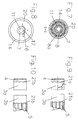
- the torque screwdriver consists of a blade whose shaft (1) has a non-circular profile cross-section - for example, a hexagonal profile cross-section - in a toothed sleeve (2) sits and until shortly before rear end is enough.
- the toothed sleeve (2) has on the circumference a substantially running over the length of toothing (2a), wherein the teeth preferably have a rectangular tooth profile.
- the two locking bushes (3a, 3b) serve with their cylindrical peripheral surface as a guide and for radial support of the mechanism described below in the cavity of the handle (14) which is closed by the cap (20).
- an internal toothing (3d Fig. 5) engage the locking bushes in the toothing (2 a) of the profile sleeve (2).
- the locking bushes On one end face, have a toothing (21) which has a wave-shaped or rounded at the tips tooth profile.
- the toothing (21) engages in a corresponding toothing of Mit videbüchsen (4, 5) of the first and second clutch.
- the Mit videbüchse (4) has on the toothing (21) opposite end side a rectangular spur toothing (4a) which engages in a uniform toothing in the handle (14) without play.
- the adjusting disc (6) is provided at the obliquely rising annular surface (12) opposite end face with a fine toothing (6a) and has on this page also a pin (7) in the holes in the locking disc (8) and the cap (20) of the handle is guided.
- a hexagon socket (11) is formed in the example, in which a key for adjusting the adjusting disc (6) can engage.
- a locking disc (8) is arranged, which has on the outer circumference a rectangular toothing (8a) which engages in a uniform internal toothing in the handle (14).
- the adjusting disc (6) facing the end face of the locking disc (8) also has a fine toothing (6a) which engages in the uniform toothing of the adjusting disc (6).
- the driving bush (5) is moved axially along the rising annular surface (12) together with the locking bush (3b) and thereby changes the bias of the coil spring (9). If a torque is transmitted to the driver bushes (4, 5) via the handle (14) and its internal toothings (4a, 15), this torque is transmitted to the toothed sleeve (2) via the detent bushings (3a, 3b) the shaft (1) forwarded.
- the bias of the coil spring (9) determines up to which torque the teeth (21) of the locking bushes (3a, 3b) and driving bushings (4, 5) remain in engagement before by rotating against each other, the transmission of the torque to the shaft (1 ) interrupt.
- 11 shows a longitudinal section through the screwing tool, in which the rear coupling parts (3b, 5) are displaced further forward by turning the adjusting disc (6) and the spring (9) is thereby pressed together and more strongly pretensioned. It can be seen here between the adjusting disc (6), or their lower portion of the obliquely rising annular surface (12) and the driving bush (5) resulting gap.
- the adjustable torque range can be determined and displayed on a scale (16, 17) at the end of the handle.
- the compression spring (9), or their spring characteristic the desired torque range can be set. It is also possible to cover with a screwdriver various torque ranges by the cap (20) unscrewed from the handle (14), the spring (9) replaced by a spring with a different characteristic and then the mechanism, cap and handle are reinstalled , As shown in Fig. 2, the adjusting disc (6) continues to serve as a bearing for the end portion (10) of the toothed sleeve (2), in particular as an axial bearing.
- FIG. 3 shows a cross section, along the line AA in FIG. 1, only through the region of the clamping device (18, 19) in the embodiment in which the shaft is replaceably inserted into the toothed sleeve.
- the clamping device (18) is formed integrally with the toothed sleeve as a cylindrical projection and has a spring tongue or a spring saddle (19) which projects inwardly into the cavity in the toothed sleeve and is resiliently deflected radially when inserting the shaft into the cavity , The spring tension of the deflected tongue or saddle holds the shaft in its axial position.
- the clamping device (18) can also be arranged between the two clutches, covered by the spring (9).
- the profile of the toothed sleeve (2) is not carried out in the region of the clamping device, the toothed sleeve slightly increased in diameter at this point.
- An alternative embodiment of the clamping device may consist of a band-ring spring and a ball, wherein the ball is seated in a radial bore in the toothed sleeve, something in the cavity (2b) protrudes the toothed sleeve and is attacked from the outside by the spring force of the band ring spring. If a shaft (1) is inserted into the cavity, the ball is radially outwardly displaced and the band-ring spring acts with a clamping force on the shaft.
- Fig. 4 the section B-B can be seen:
- Fig. 5 the section C-C, it can be seen how the locking bush (3b) with her cylindrical peripheral surface in the cavity of the handle (14) rotatably mounted and supported - as well as the locking bushing (3a) - and a Internal toothing (3d) connected to the external toothing (2a) of the toothed sleeve (2) is.
- Fig. 7 shows how the locking disc (8) on the external toothing (8a) is non-rotatably connected to the handle (14) and the pin (7) with the hexagon inner profile (11) rotatably mounted in the locking disc (8) is.
- the mark (16) on the pin (7) and the scale (17) on the cap (20) is shown as a principle.
- the screwing tool is expediently let into the cap a dial or be attached in another way, where the adjustable torque range is displayed directly. As stated above, it depends on the spring characteristic of the inserted spring (9) and is determined by calibration.
- the construction of adjusting disc (6) and driving sleeve (5) - with the inclined rising annular surfaces (12) allows a very accurate calibration.
- the increase angle of the annular surface (12) on the driver sleeve (5) and adjusting disc (6) determines the extent to which the transmittable torque changes at a certain displacement angle of the adjusting disc (6).
- the driver sleeve (5) and locking bushing (3b) are displaced only by a small distance and thus the spring (9) changed by this distance in length at a certain adjustment angle, correspondingly low is the change in the spring bias and the transmittable torque.
- Figures 9 and 10 show the couplings with different designs (21a, 21b) of the tooth forms. Due to the tooth shape, the torque range also be influenced. Is the flank angle ( ⁇ ) related on the axis of rotation of the clutch, large, so the teeth are smaller Torque slip past each other as if the angle ⁇ is small. Is the Flank angle 0 °, as in Fig. 10 in the direction of rotation to the left, so releases the clutch in this direction no longer off. In addition, at lower Loosening resistance of the screw, a reverse rotation of the screw avoided.
- Figures 11 and 12 show a more accurate form of the subsequent wave-shaped Tooth profiles of the toothing (21) shown in Figures 1, 2, 9, 10th and 11 is shown only in principle.
- the arrangement of two clutches and the other construction design according to the invention make it possible to transmit higher torques than if only one clutch were present, because the specific load of the components is lower, in particular the engaged form elements.
- the torque to be transmitted from the handle to the shaft is introduced into the transmission device at two points, namely via the front toothing (4a) of the driving bush (4) and via the toothing (5a) of the driving bush (5) or the internal toothing (15) of the handle (14).
- the burden of a transmission point for the torque or a clutch thus halved compared to such a device with only one clutch. It is therefore possible, all components except for the shaft (1), the spring (9) and the discs (13) made of plastic of suitable types by injection molding.
- Polyamide (PA) and polyoxymethylene (POM) have been found to be suitable types of plastic, especially as mating in those parts which interact in a sliding manner.
- a pairing was found to be particularly advantageous in which POM is compounded with Teflon.
- the friction of the mutually sliding surfaces is additionally reduced, in particular on the toothing (21) of latching and driving bush.
- influences of the friction are again reduced to the tripping torque and further increases the accuracy of the device.
- screwing tools with a preselected torque limiting device are also used in orthopedic surgery and it is necessary to sterilize them after use. Dry air sterilizers reach a temperature of 180 ° C. At this temperature, no permanent change in shape should occur on the parts of the screwing tool.
- the screwing tool is therefore made of plastics whose dimensional stability is still guaranteed up to a temperature of about 220 ° C.
- Parts such as the toothed sleeve (2) the latching bushes (3a, 3b) the Mitauerbüchsen (4, 5) the adjusting disc (6) the locking disc (8) or individual of these parts may alternatively be made of metal, for example as sintered parts in one Metal composition and / or metal mating, the good sliding properties, which are against each other, or even made of steel, stretched or formed by pressing.
- the handle (14) and the cap (20) may be made of metal about die-cast aluminum, and have a surface finished by anodization.
- the handle, cap and other, in particular statically loaded part may be made of stainless steel, such as wax-melting or powdered metal in the injection molding sintering process.
- the metal version is considered, if with the same dimensions as in the plastic version higher torques to be transmitted or, when used in orthopedic surgery, an unrestricted sterilization should be given. Since in an embodiment of the handle made of metal for weight reduction she wall thickness of sufficient durability is designed less on the requirements for a good feel, is provided in a variant of the main body of the handle, which has a non-circular outer contour in cross-section, a grip sleeve preferably elastic plastic, whose outer shape is designed according to ergonomic requirements.
- This grip sleeve is removed after use from the body and disposed of, especially if it is made of a resilient, less temperature-resistant plastic and can not be sterilized.
- This embodiment variant is shown by way of example in FIG. 13. In it are (14) the handle made of metal, (22) the grip sleeve made of elastic plastic.
- the setting device for the data to be transmitted is also advantageous Torque.
- the interaction of the obliquely rising ring surfaces (12) and the fine toothing (6a) on the locking disc (8) and on the adjusting disc (6) allow small adjustment steps, thus a precise adjustment the bias of the spring (9) and thus the tripping torque.
- the bias of the spring holds the locking disc in the set Location firm.
- the biasing force of the spring (9) is evenly distributed to both clutches, and on the one hand via the Mitauerbüchse (4 ), on the other side via the adjusting disc (6) and locking disc (8) in the handle (14) or the cap (20) derived, the tensioning force does not act with axial load on the toothed sleeve and the axial bearing.
Abstract
Description
Die Erfindung betrifft ein Schraubwerkzeug mit einer Vorrichtung zum Einstellen eines vorgewählten Drehmomentes, bei dessen Erreichen die Übertragung des Drehmomentes von dem Antriebsteil in das Abtriebsteil unterbrochen wird. Vorrichtungen dieser Gattung sind in relativ vielen Ausführungsarten bekannt, sowohl zum Einsatz bei Kraftschraubern als auch bei Hand- Schraubwerkzeugen. Bei den bekannten Vorrichtungen kommen verschiedene Systeme zur Anwendung.The invention relates to a screwing tool with a device for adjusting a preselected torque, when it reaches the transmission of the torque from the drive part in the driven part interrupted becomes. Devices of this type are in relatively many embodiments known both for use in power wrenches and in Hand screwdrivers. In the known devices come different Systems for use.
Von besonderem Interesse sind im Bereich der Erfindung solche Systeme, bei denen das Antriebsteil achszentrisch zum Abtriebsteil angeordnet ist.Of particular interest in the field of the invention are such systems, in which the drive part is arranged achszentrisch to the output part.
Die im Vergleich mit dem Erfindungsgegenstand zu beachtenden Systeme werden beispielhaft mit ihrem Funktionsprinzip beschrieben:The systems to be considered in comparison with the subject invention are described by way of example with their functional principle:
Ein Schraubendreher mit Drehmomentbegrenzung gemäß US 5,746,298
weist einen komplizierten Aufbau der Kupplungsmechanik auf, deren Teile
aus Metall bestehen. In einem Griff ist ein Schaft gelagert, der Schaft weist
ein sechseckiges Endstück auf, das von fingerartigen Segmenten einer in
Längsrichtung teilweise geschlitzten Hülse umgriffen wird. Ein in Längsrichtung
in der Höhlung des Griffes verstellbarer Kragen umschließt die fingerartigen
Segmente und wirkt mit einer Radialkraft auf diese Weise ein, eine entsprechende
Radialkraft wirkt von den Enden der fingerartigen Segmente auf
das sechseckige Endstück des Schaftes. Je näher der Kragen am Ende der
fingerartigen Segmente steht, um so geringer ist deren Möglichkeit, radial
auszufedern und ein Durchdrehen des sechseckigen Endstückes zu erlauben
- um so höher ist also das Auslöse-Drehmoment. Die Kupplung ist teuer
in der Herstellung. Zum Voreinstellen eines Auslösedrehmomentes muss der
Griff teilweise demontiert werden, (Spalte 6, Zeilen 42 bis 49), das System ist
zu umständlich für Einsatz mit wechselnden Drehmomenten. A screwdriver with torque limiter according to US 5,746,298
has a complicated structure of the clutch mechanism, whose parts
Made of metal. In a handle, a shaft is mounted, the shaft has
a hexagonal tail, which consists of finger-like segments of an in
Longitudinal partially slotted sleeve is embraced. One in the longitudinal direction
adjustable collar in the hollow of the handle encloses the finger-like
Segments and acts with a radial force in this way, a corresponding one
Radial force acts on the ends of the finger-like segments
the hexagonal end of the shaft. The closer the collar is at the end of the
finger-like segments is, the lower is their ability to radial
auszufedern and allow a spin of the hexagonal end piece
- So the higher is the tripping torque. The coupling is expensive
in production. For presetting a triggering torque, the
Handle to be partially dismantled, (
Aus OS 26 47 996 ist ein System bekannt, das im wesentlichen aus Axial-Kugel- oder Rollenlagern besteht, welche durch eine Schraubenfeder vorgespannt sind. Die Kugeln oder Rollen sitzen dabei in in den Lagerscheiben eingeformten Rastmulden und werden dort durch die Vorspannung gehalten. Eine der Lagerscheiben ist mit dem Antriebsteil verbunden, die andere mit dem Abtriebsteil. Übersteigt das Drehmoment einen vorgegebenen Wert, so wird die in Umfangsrichtung wirkende Kraft größer als die durch die Vorspannung der Feder im Sitz der Kugel oder Rollen wirkende form- und reibungsschlüssige Kraft, die Kugeln oder Rollen steigen aus den Rastmulden, die Lagerscheiben verdrehen sich gegeneinander, die DrehmomentÜbertragung wird unterbrochen.From OS 26 47 996 a system is known which consists essentially of axial ball or roller bearings, which is biased by a coil spring are. The balls or rollers sit in the bearing discs molded locking recesses and are held there by the bias. One of the bearing washers is connected to the drive part, the other with the stripping section. If the torque exceeds a predetermined value, then the force acting in the circumferential direction is greater than that by the bias the spring in the seat of the ball or rollers acting positive and frictional Force, the balls or rollers get out of the detent wells, the bearing discs twist against each other, the torque transmission will be interrupted.
Bei einer Vorrichtung gemäß OS 24 27 352 besteht das Antriebsteil aus einem Schaft mit einer tellerartigen Vergrößerung des Schaftes an einem Ende. Die tellerartige Vergrößerung weist an der Stirnseite in Umfangsrichtung eine wellenförmige Verzahnung auf und bildet ein Mitnehmer-Element. Das zweite Mitnehmer-Element bildet eine gleiche tellerartige Vergrößerung mit Verzahnung am Schaftende des Abtriebsteiles. Durch eine Druckfeder, ein Paket von Tellerfedern oder eine Schraubenfeder, werden die Mitnehmer - Elemente aufeinander gepreßt.In a device according to OS 24 27 352, the drive part consists of a Shaft with a plate-like enlargement of the shaft at one end. The plate-like enlargement has at the front side in the circumferential direction a wave-shaped toothing and forms a driver element. The second driver element forms a same plate-like magnification Gearing on the shaft end of the driven part. By a compression spring, a Package of disc springs or a coil spring, become the driver - Elements pressed together.
Aus OS 101 43 181 A1 ist eine Vorrichtung zur Begrenzung des von einem Schraubwerkzeug übertragbaren Drehmomentes bekannt. Die Kupplung zwischen Antriebsteil - dem Griff- und Abtriebsteil - dem Schaft - besteht im wesentlichen aus einer Käfighülse mit schlitzartigen Durchbrechungen der Hülsenwand und Kugeln, die mit einem Teil ihres Körper in die Schlitze hineinragen, mit dem Hauptteil des Körper jedoch in Rastvertiefungen von Andrucktellern eingreifen, welche ihrerseits durch eine Druckfeder über die Kugeln gegeneinander verspannt sind. Bei Überschreiten eines durch die Vorspannung der Feder vorgegebenen Drehmomentes werden die Kugeln aus den Rastvertiefungen in die Durchbrechungen der Hülsenwand gedrückt, die Drehmomentübertragung wird unterbrochen. Die Konstruktion entspricht im Grundprinzip der in OS 26 47 996 beschriebenen Konstruktion. From OS 101 43 181 A1 is a device for limiting the of a Wrenching tool transmissible torque known. The coupling between drive part - the handle and driven part - the shaft - consists in essentially from a cage sleeve with slot-like openings of the Sleeve wall and balls that protrude into the slots with part of their body, with the main part of the body, however, in locking recesses of Andrucktellern engage, which in turn by a compression spring on the balls are braced against each other. When exceeding one by the bias the spring predetermined torque, the balls are made pressed the locking recesses in the openings of the sleeve wall, the Torque transmission is interrupted. The construction corresponds to Basic principle of the construction described in OS 26 47 996.
Die Konstruktion gemäß OS 101 43 181 A1 ist in der Herstellung teuer, weil die Kupplung aus Präzisionsteilen aus Metall besteht.The construction according to OS 101 43 181 A1 is expensive to manufacture because the coupling is made of precision metal parts.
Bei einem Schraubendreher mit Drehmomentbegrenzung gemäß EP 1 092
510 A2 weist ein Schaft eine ballige Endfläche auf zur Übertragung einer
Axialkraft auf die innere Oberfläche des oberen Griffteiles, die Axialkraft einer
Schraubenfeder wird in Richtung zum oberen Griffteil auf eine Buchse übertragen
welche drehbar auf dem Schaft aufgesteckt ist. Die Buchse weist auf
der zum oberen Griffteil hinwendeten Stirnseite eine Verzahnung und am
Umfang Nuten auf, in die Rippen eingreifen, welche von der Innenseite der
Griffhöhlung radial vorstehen. Über diese Rippen wird ein Drehmoment vom
Griff in die Buchse eingeleitet und über die stirnseitige Verzahnung in eine
zweite Verzahnung, die auf der Unterseite einer tellerartigen Vergrößerung
des Schaftes eingeformt ist. Die beiden Verzahnungen weisen in einer Richtung
abgeschrägte, in der anderen Richtung gerade, parallel zur Achse des
Schaftes verlaufende Flanken auf.
Wird ein Drehmoment in Richtung der schräg verlaufenden Zahnflanken aufgebracht,
so hebt sich die Verzahnung der Buchse aus der Verzahnung am
Teller des Schaftes, wenn ein durch die Federspannung eingestelltes
Drehmoment überschritten wird. Dadurch wird die Einleitung des Drehmomentes
vom Griff in den Schaft unterbrochen. Nachteilig ein dieser Konstruktion
ist, dass die Axialkraft der Feder über die Verzahnung auf den Teller des
Schaftes und somit über seine ballige Endfläche auf die innere Oberfläche
des Griffes wirkt. Diese Axialkraft überlagert sich mit der Axialkraft, die bei
Benutzung des Schraubendrehers von der Hand über den Griff und den
Schaft in die Klinge des Schraubendrehers eingeleitet wird. Das hat zur Folge,
dass die Reibung im Bereich der Anlagefläche der Endfläche des Schaftes
mit der inneren Oberfläche des Griffes relativ hoch ist. Infolgedessen wird
das Auslöse-Drehmoment nicht alleine durch die Federspannung, sondern
auch durch die von der Hand ausgeübten Axialkraft beeinflußt, das gewünschte
Auslösedrehmoment wird in der Praxis nicht mit Genauigkeit eingehalten. In a screwdriver with torque limiter according to
If a torque is applied in the direction of the oblique tooth flanks, then the toothing of the bushing lifts from the toothing on the plate of the shank when a torque set by the spring tension is exceeded. As a result, the introduction of the torque is interrupted by the handle in the shaft. A disadvantage of this construction is that the axial force of the spring on the teeth of the plate of the shaft and thus acts on its spherical surface on the inner surface of the handle. This axial force is superimposed by the axial force that is introduced when using the screwdriver from the hand over the handle and the shaft in the blade of the screwdriver. As a result, the friction in the region of the contact surface of the end surface of the shaft with the inner surface of the handle is relatively high. As a result, the tripping torque is influenced not only by the spring tension but also by the axial force exerted by the hand, the desired tripping torque is not met with accuracy in practice.
Vorteilhaft ist zwar, dass die wesentlichen Teile aus Kunststoff im Spritzgießverfahren hergestellt sind, nachteilig ist jedoch, dass bei dieser Konstruktion nur relativ niedrige Drehmomente übertragen werden können. Bei höheren Drehmomenten treten plastische Verformungen an wichtigen Elementen der Mechanik auf, die Auslösegenauigkeit vermindert sich stark, unter Umständen ist die Funktion überhaupt nicht mehr gewährleistet.Although it is advantageous that the essential parts made of plastic by injection molding are disadvantageous, however, that in this construction only relatively low torques can be transmitted. At higher Torques occur plastic deformation on important elements of the Mechanics on, the tripping accuracy decreases greatly, under certain circumstances the function is no longer guaranteed.
Die bekannten Ausführungen sind relativ teuer in der Herstellung, weil sie im Aufbau kompliziert und die Teile zumeist aus Metall hergestellt sind. Auch ist die Einstellung oft nicht einfach durchzuführen und die Ungenauigkeit beim Auslösen zu hoch. In neuerer Zeit erhöht sich der Bedarf für Schraubwerkzeuge mit einstellbaren Höchstwerten für das übertragene Drehmoment, wobei der Auslöse-Drehmoment in einem gewissen Bereich variabel einstellbar sein soll. Anwendungsgebiete sind die Montage, auch im Service, von elektrischen Bauteilen, die Verschraubung von Kunststoffteilen und die Befestigung von Schneidplatten von Zerspanungswerkzeugen. Mit dem steigenden Bedarf ist die Forderung der Anwender verbunden, derartige Schraubwerkzeuge kostengünstiger anzubieten.The known designs are relatively expensive to manufacture because they are in the Structure complicated and the parts are mostly made of metal. Also is Often the attitude is not easy to carry out and the inaccuracy of Trigger too high. Recently, the need for screwdriving tools has increased with adjustable maximum values for the transmitted torque, wherein the tripping torque can be variably adjusted in a certain range should be. Fields of application are the assembly, also in the service of electrical Components, the screwing of plastic parts and the attachment of inserts of cutting tools. With the rising Demand is the requirement of users associated with such screwing tools to offer cheaper.
Die Aufgabe ist es, ein Schraubwerkzeug mit einer Vorrichtung zur Begrenzung
eines vorgewählten Drehmomentes zu entwickeln, das kostengünstig
herstellbar ist, mit Drehmomenten der im Anwendungsbereich geforderten
Höhe belastet werden kann, schnell verstellbar ist und dessen Funktionsgenauigkeit
über eine lange Gebrauchsdauer erhalten bleibt. Diese Aufgabe
wird durch den Erfindungsgegenstand mit den Merkmalen von Anspruch 1
gelöst.
Die wesentlichen Merkmale des Erfindungsgegenstandes sind: die von einem
Griff als Antriebsteil in die Klinge als Abtriebsteil einzuleitenden
Drehmomente werden an zwei Stellen in eine Drehmoment-Begrenzungsmechanik
übertragen, die zwei auf einer Zahnhülse angeordneten Kupplungen
aufweist welche durch eine zwischen den Kupplungen angeordnete
Druckfeder, vorzugsweise eine Schraubenfeder, mit einer Vorspannung beaufschlagt
werden. Die Kupplungen bestehen aus zwei zylindrischen Teilen. The object is to develop a screwing tool with a device for limiting a preselected torque, which is inexpensive to produce, can be loaded with torques required in the scope height, is quickly adjustable and its functional accuracy is maintained over a long period of use. This object is achieved by the subject invention having the features of
The essential features of the subject invention are: to be initiated by a handle as a drive part in the blade as a driven part torques are transmitted at two points in a torque limiting mechanism having two arranged on a toothed sleeve couplings which arranged by a clutch between the compression spring, preferably a Coil spring to be biased. The couplings consist of two cylindrical parts.
Je ein Teil der beiden Kupplungen, die Rastbuchse, ist durch eine Innenverzahnung
mit der Außenverzahnung der Zahnhülse formschlüssig und verschiebbar
verbunden. Das andere Teil der Kupplungen, die Mitnehmerbüchse,
ist durch eine Verzahnung mit dem Griff verbunden, die Zahnhülse ist
über die Zahnkamm- Flächen in einer Bohrung der Mitnehmerbüchse drehbar
geführt. Die einander zugekehrten Stirnseiten der Kupplungsteile weisen
ineinandergreifende Verzahnungen auf. Durch die Vorspannung der Feder
werden die Verzahnungen in Eingriff gehalten, bis das über die mit dem Griff
verbundenen Mitnehmerbüchse eingeleitete Drehmoment so groß ist, dass
es den in der Verzahnung wirkenden Reibungs- Formschluß löst, die Zähne
sich gegeneinander verdrehen und außer Eingriff kommen, so daß die Übertragung
des Drehmomentes unterbrochen wird. Die ineinander greifende
Verzahnung von Rastbuchsen und Mitnehmerbüchsen wird zweckmäßigerweise
in ihrem Zahnprofil so gewählt, dass die Zähne in Drehrichtung beim
Einschrauben unter einem Winkel α schräg ansteigende Zahnflanken aufweisen,
die Zahnkanten leicht abgerundet und die Zahnkämme abgeflacht
oder ebenfalls abgerundet sind. Die Zahnflanken in Drehrichtung zum Lösen
von Schrauben verlaufen dagegen unter einem Winkel von 0° oder unter einem
sehr kleinen Winkel, bezogen auf die Drehachse der Vorrichtung, da
beim Ausdrehen von Schrauben das erforderliche Drehmoment nur durch
den mehr oder weniger festen Sitz der Schraube bestimmt wird, nicht aber
durch eine definierte Vorgabe. Außerdem wird bei einem Flankenwinkel von
0° vermieden, dass die Schraube beim Wiedereingreifen der Verzahnungen
über schräge Flanken wieder zurückgedreht wird.
Zum Einstellen des Auslöse- Drehmomentes wird die hintere Kupplung axial
verschoben, indem auf eine in Umfangsrichtung schräg ansteigende Ringfläche
an der hinteren Stirnseite der Mitnehmerbüchse die in gleicher Weise
ansteigende Stirnseite einer Verstellscheibe einwirkt, die von dem Hinterende
des Griffes aus verdreht werden kann. Durch die axiale Verschiebung der
hinteren Kupplung verändert sich die Vorspannung der Druckfeder, dadurch
der Reibungs- Formschluß in der Verzahnung der Kupplungen und somit die
Höhe des Auslöse- Drehmomentes.
Die Rückseite der Verstellscheibe ist in Umfangsrichtung mit einer relativ feinen
Stirnverzahnung versehen. Am Boden der Höhlung der Kappe ist eine
Rastscheibe eingesetzt und über eine Umfangsverzahnung drehfest mit der
Kappe verbunden. Auf der Verstellscheibe zugewendeten Seite weist die
Rastscheibe eine Stirnverzahnung auf, die der Stirnverzahnung an der Rückseite
der Verstellscheibe entspricht. Die Axialkraft der Feder presst über
hintere Kupplung die Verstellscheibe mit ihrer Verzahnung in die Verzahnung
der Rastscheibe. Im Zusammenwirken der beiden Verzahnungen werden die
jeweiligen Positionen fixiert, die sich beim Einstellen eines gewünschten
Auslösedrehmomentes durch Verdrehen der Verstellscheibe ergeben.
In die Zahnhülse ist die Klinge eines Schraubendrehers oder ein Schaft mit
Aufnahmekopf für auswechselbare Werkzeuge fest oder auswechselbar eingesetzt.
Bei Drehung der Zahnhülse werden die Klinge oder der Schaft von
der Zahnhülse mitgenommen.
Die Zahnhülse stützt sich axial am Grund einer Bohrung in der Verstellscheibe
ab. Die beim Gebrauch des Schraubwerkzeuges von der Hand des Benutzers
ausgeübte Axialkraft wird somit von Griff / Kappe über die Rastscheibe
und die Verstellscheibe auf die Zahnhülse übertragen. Die Vorspannkraft
der Feder wirkt nur auf die beiden Kupplungen, nicht jedoch auch
auf das Axiallager der Zahnhülse.Depending on a part of the two clutches, the locking bush is positively and slidably connected by an internal toothing with the external toothing of the toothed sleeve. The other part of the couplings, the drive bush, is connected by a toothing with the handle, the toothed sleeve is rotatably guided over the Zahnkamm- surfaces in a bore of Mitnehmerbüchse. The mutually facing end faces of the coupling parts have interlocking teeth. Due to the bias of the spring, the teeth are held in engagement until the torque introduced via the driving bush connected to the handle is so great that it releases the frictional engagement acting in the toothing, causing the teeth to rotate relative to one another and disengage that the transmission of the torque is interrupted. The interlocking teeth of locking bushings and Mitnehmerbüchsen is suitably chosen in their tooth profile so that the teeth have α in the direction of rotation when screwing at an angle obliquely rising tooth flanks, the tooth edges slightly rounded and the tooth combs are flattened or rounded. The tooth flanks in the direction of rotation for loosening screws, however, run at an angle of 0 ° or at a very small angle relative to the axis of rotation of the device, since when turning screws the required torque is determined only by the more or less firm seat of the screw but not by a defined specification. In addition, it is avoided with a flank angle of 0 °, that the screw when re-engaging the gears on inclined flanks is rotated back.
To set the release torque, the rear clutch is axially displaced by acting on a circumferentially obliquely rising annular surface on the rear end of the Mitnehmerbüchse the same rising end face of an adjusting disc, which can be rotated from the rear end of the handle. Due to the axial displacement of the rear clutch, the bias of the compression spring, thereby the frictional engagement in the teeth of the clutches and thus the height of the tripping torque changes.
The rear of the adjusting is provided in the circumferential direction with a relatively fine spur toothing. At the bottom of the cavity of the cap, a locking disk is inserted and rotatably connected via a circumferential toothing with the cap. On the adjusting disk facing side, the locking disk has a spur gear toothing, which corresponds to the spur toothing on the back of the adjusting disc. The axial force of the spring presses the adjusting disc with its toothing into the toothing of the locking disc via the rear coupling. In cooperation of the two gears the respective positions are fixed, which result in setting a desired release torque by turning the adjusting.
In the toothed sleeve, the blade of a screwdriver or a shaft with recording head for interchangeable tools is used fixed or replaceable. Upon rotation of the toothed sleeve, the blade or the shaft are taken from the toothed sleeve.
The toothed sleeve is supported axially at the bottom of a hole in the adjusting disc. The axial force exerted by the user's hand during use of the screwing tool is thus transferred from the handle / cap to the toothed sleeve via the locking disk and the adjusting disk. The biasing force of the spring acts only on the two couplings, but not on the thrust bearing of the toothed sleeve.
Der Erfindungsgegenstand wird durch die Zeichnungen beispielhaft dargestellt.
Es zeigen:
- Fig. 1
- einen Längsschnitt durch das Schraubwerkzeug mit einer Vorrichtung
zur Begrenzung eines vorgewählten Drehmomentes mit den offenliegenden
Teilen der Vorrichtung.
Darin sind:- (1) der Schaft (Abtriebsteil)
- (2) die Zahnhülse mit Außenverzahnung
- (2a) die Außenverzahnung der Zahnhülse
- (3a) die Rastbuchse der ersten Kupplung
- (3b) die Rastbuchse der zweiten Kupplung
- (4) die Mitnehmerbuchse der ersten Kupplung
- (4a) die Stirnverzahnung der Mitnehmerbüchse
- (5) die Mitnehmerbüchse der zweiten Kupplung
- (5a) die Außenverzahnung der Mitnehmerbüchse (5)
- (21) die Stirnverzahnung an den Rastbuchsen (3a, 3b) und Mitnehmerbüchsen (4, 5)
- (6) die Verstellscheibe
- (6a) eine feine Stirnverzahnung an den einander zugewandten Stirnseiten der Verstellscheibe (6) und der Rastscheibe (8)
- (7) ein mit der Verstellscheibe einstückig verbundener Zapfen
- (8) die Rastscheibe
- (8a) die Umfangsverzahnung der Rastscheibe (8)
- (9) die Druckfeder (Schraubenfeder)
- (11) eine in den Zapfen (7) eingeformte Höhlung
- (12) in Umfangsrichtung schräg ansteigende Ringflächen
- (13) Stahlscheiben
- (14) der Griff
- (15) die Innenverzahnung im Griff
- (18) eine Klemmeinrichtung zum axialen Halten eines in der Zahnhülse (2) auswechselbar gelagerten Schaftes (1)
- (19) eine Federzunge oder Federsattel in der Klemmeinrichtung, einstückig eingeformt
- (20) die Kappe
- Fig. 2
- einen zweiten Längsschnitt, der in der unteren Hälfte bis zu dem in der
Zahnhülse gelagerten Schaft führt.
Darin sind:- (1) der in der Zahnhülse (2) gelagerte Schaft
- (2) die Zahnhülse mit Außenverzahnung
- (2a) die Außenverzahnung der Zahnhülse
- (3a) die Rastbuchse der ersten Kupplung
- (3b) die Rastbuchse der zweiten Kupplung
- (4) die Mitnehmerbüchse der ersten Kupplung
- (4a) eine Stirnverzahnung der Mitnehmerbüchse
- (5) die Mitnehmerbüchse
- (5a) die Außenverzahnung der Mitnehmerbüchse (5)
- (21) die Stirnverzahnung an den Rastbuchsen (3a, 3b) und Mitnehmerbüchsen (4, 5)
- (6) die Verstellscheibe
- (6a) eine feine Stirnverzahnung an den einander zugewandten Stirnseiten der Verstellscheibe (6) und der Rastscheibe (8)
- (7) ein mit der Verstellscheibe einstückig verbundener Zapfen
- (8) die Rastscheibe
- (8a) die Umfangsverzahnung der Rastscheibe (8)
- (9) die Druckfeder (Schraubenfeder)
- (10) der Endabschnitt der Zahnhülse (2)
- (11) eine in den Zapfen (7) eingeformte Höhlung
- (12) in Umfangsrichtung schräg ansteigende Ringflächen
- (14) der Griff
- (20) die Kappe
- Fig. 3
- einen Querschnitt entlang der Linie A-A in Fig. 1 durch den Bereich
der Klemmvorrichtung zum axialen Halten eines in der Höhlung der
Zahnhülse auswechselbar gelagerten Schaftes, die linke Seite stellt
die Situation mit eingesetztem Schaft dar, die rechte Seite ohne eingesetzten
Schaft
Darin sind:- (1) der Schaft (Abtriebsteil)
- (2b) die Höhlung der Zahnhülse (2)
- (14) der Griff
- (18) die Klemmeinrichtung
- (19) die Federzunge der Klemmeinrichtung
- Fig. 4.
- einen Querschnitt entlang der Linie B-B in Fig. 1 ohne in die
Zahnhülse (2) eingesetzten Schaft (1).
Darin sind:- (2) die Zahnhülse mit Außenverzahnung
- (2a) die Außenverzahnung der Zahnhülse
- (2b) die Höhlung der Zahnhülse (2)
- (4a) die Stirnverzahnung der Mitnehmerbüchse (4)
- (14) der Griff
- Fig. 5.
- einen Querschnitt entlang der Linie C-C in Fig. 1 ohne in die
Zahnhülse (2) eingesetzten Schaft (1).
Darin sind:- (2) die Zahnhülse mit Außenverzahnung
- (2a) die Außenverzahnung der Zahnhülse
- (2b) die Höhlung der Zahnhülse (2)
- (3b) eine Rastbuchse
- (3d) die Innenverzahnung der Rastbuchse (3b)
- (14) der Griff
- Fig. 6.
- einen Querschnitt entlang der Linie D-D in Fig. 1 ohne in die
Zahnhülse (2) eingesetzten Schaft (1).
Darin sind:- (2) die Zahnhülse mit Außenverzahnung
- (2a) die Außenverzahnung der Zahnhülse
- (2b) die Höhlung der Zahnhülse (2)
- (5) eine Mitnehmerbüchse
- (5a) die Umfangsverzahnung der Mitnehmerbüchse
- (14) der Griff
- (15) die Innenverzahnung des Griffes
- Fig. 7.
- einen Querschnitt entlang der Linie E-E in Fig. 1.
Darin sind:- (7) der Zapfen der Stellscheibe (6)
- (8) eine Rastscheibe
- (8a) die Umfangsverzahnung der Rastscheibe (8)
- (14) der Griff
- (20) die Kappe
- Fig. 8.
- eine Ansicht von hinten auf die Kappe des Griffes mit der Skalierung
für die Auslöse-Drehmoment-Einstellung
Darin sind:- (7) der Zapfen
- (11) das Innenprofil im Zapfen
- (14) der Griff
- (16) die Markierung auf dem Zapfen (7)
- (17) die Skala auf der Kappe (20)
- (20) die Kappe
- Fig. 9
- eine Seitenansicht der Rastbuchsen
3a und 3b sowie der Mitnehmerbuchsen 4und 5.
Darin ist:- (21a) eine Verzahnung mit ungleich schrägen Zahnflanken
- (α) der Flankenwinkel bezogen auf die Drehachse
- Fig. 10
- eine Seitenansicht der Rastbuchsen
3a und 3b sowie der Mitnehmerbuchsen 4und 5.
Darin ist:- (21b) eine Verzahnung, bei der der Winkel der Zahnflanken in einer Drehrichtung 0° in Bezug auf die Drehachse beträgt
- Fig. 11
- zeigt einen Längsschnitt in dem die hintere Kupplung weiter nach
vorne verschoben und die Feder stärker vorgespannt ist.
Darin sind:- (3a, 3b) die zwei Rastbuchsen
- (5) eine Mitnehmerbüchse
- (6) eine Verstellscheibe
- (7) ein mit der Verstellscheibe einstückig verbundener Zapfen
- (9) eine Druckfeder (Schraubenfeder)
- (11) eine in den Zapfen (7) eingeformte Höhlung
- Fig. 12
- zeigt einen vergrößerten Ausschnitt der wellenförmigen Verzahnung (21) an den Rastbuchsen (3a, 3b) und Mitnehmerbuchsen (4, 5)
Show it:
- Fig. 1
- a longitudinal section through the screwing with a device for limiting a preselected torque with the exposed parts of the device.
In it are:- (1) the shaft (driven part)
- (2) the toothed sleeve with external toothing
- (2a) the external toothing of the toothed sleeve
- (3a) the locking bush of the first clutch
- (3b) the locking bush of the second clutch
- (4) the driving bush of the first clutch
- (4a) the spur toothing of the driving bush
- (5) the drive bush of the second clutch
- (5a) the outer toothing of the driving bush (5)
- (21) the spur toothing on the locking bushings (3a, 3b) and driving bushes (4, 5)
- (6) the adjusting disc
- (6a) a fine spur toothing on the mutually facing end faces of the adjusting disc (6) and the locking disc (8)
- (7) a pin integrally connected to the adjusting disc
- (8) the locking disc
- (8a) the peripheral toothing of the locking disc (8)
- (9) the compression spring (coil spring)
- (11) a cavity formed in the pin (7)
- (12) in the circumferential direction obliquely rising annular surfaces
- (13) Steel discs
- (14) the handle
- (15) the internal teeth in the handle
- (18) a clamping device for axially holding a shaft (1) which is exchangeably mounted in the toothed sleeve (2)
- (19) a spring tongue or spring saddle in the clamping device, integrally molded
- (20) the cap
- Fig. 2
- a second longitudinal section, which leads in the lower half up to the shaft mounted in the tooth sleeve.
In it are:- (1) the shaft mounted in the toothed sleeve (2)
- (2) the toothed sleeve with external toothing
- (2a) the external toothing of the toothed sleeve
- (3a) the locking bush of the first clutch
- (3b) the locking bush of the second clutch
- (4) the drive bush of the first clutch
- (4a) an end toothing of the driving bush
- (5) the driving bush
- (5a) the outer toothing of the driving bush (5)
- (21) the spur toothing on the locking bushings (3a, 3b) and driving bushes (4, 5)
- (6) the adjusting disc
- (6a) a fine spur toothing on the mutually facing end faces of the adjusting disc (6) and the locking disc (8)
- (7) a pin integrally connected to the adjusting disc
- (8) the locking disc
- (8a) the peripheral toothing of the locking disc (8)
- (9) the compression spring (coil spring)
- (10) the end portion of the toothed sleeve (2)
- (11) a cavity formed in the pin (7)
- (12) in the circumferential direction obliquely rising annular surfaces
- (14) the handle
- (20) the cap
- Fig. 3
- a cross-section along the line AA in Fig. 1 by the region of the clamping device for axially holding a replaceable in the cavity of the tooth sleeve mounted shaft, the left side represents the situation with inserted shaft, the right side without inserted shaft
In it are:- (1) the shaft (driven part)
- (2b) the cavity of the toothed sleeve (2)
- (14) the handle
- (18) the clamping device
- (19) the spring tongue of the clamping device
- Fig. 4.
- a cross section along the line BB in Fig. 1 without inserted into the toothed sleeve (2) shank (1).
In it are:- (2) the toothed sleeve with external toothing
- (2a) the external toothing of the toothed sleeve
- (2b) the cavity of the toothed sleeve (2)
- (4a) the spur toothing of the driving bush (4)
- (14) the handle
- Fig. 5.
- a cross section along the line CC in Fig. 1 without in the toothed sleeve (2) inserted shaft (1).
In it are:- (2) the toothed sleeve with external toothing
- (2a) the external toothing of the toothed sleeve
- (2b) the cavity of the toothed sleeve (2)
- (3b) a locking bush
- (3d) the internal toothing of the locking bush (3b)
- (14) the handle
- Fig. 6.
- a cross section along the line DD in Fig. 1 without in the toothed sleeve (2) inserted shaft (1).
In it are:- (2) the toothed sleeve with external toothing
- (2a) the external toothing of the toothed sleeve
- (2b) the cavity of the toothed sleeve (2)
- (5) a driving bush
- (5a) the circumferential toothing of the driving bush
- (14) the handle
- (15) the internal toothing of the handle
- Fig. 7.
- a cross section along the line EE in Fig. 1st
In it are:- (7) the pin of the adjusting disc (6)
- (8) a locking disk
- (8a) the peripheral toothing of the locking disc (8)
- (14) the handle
- (20) the cap
- Fig. 8.
- a view from the back on the cap of the handle with the scale for the trigger torque setting
In it are:- (7) the pin
- (11) the inner profile in the pin
- (14) the handle
- (16) the marking on the pin (7)
- (17) the scale on the cap (20)
- (20) the cap
- Fig. 9
- a side view of the locking
bushes Mitnehmerbuchsen
In it is:- (21a) a toothing with uneven beveled tooth flanks
- (α) the flank angle with respect to the axis of rotation
- Fig. 10
- a side view of the locking
bushes Mitnehmerbuchsen
In it is:- (21b) a toothing in which the angle of the tooth flanks in a rotational direction is 0 ° with respect to the axis of rotation
- Fig. 11
- shows a longitudinal section in which the rear clutch moved further forward and the spring is biased more.
In it are:- (3a, 3b) the two locking bushes
- (5) a driving bush
- (6) an adjusting disc
- (7) a pin integrally connected to the adjusting disc
- (9) a compression spring (coil spring)
- (11) a cavity formed in the pin (7)
- Fig. 12
- shows an enlarged section of the wave-shaped toothing (21) on the locking bushes (3a, 3b) and Mitnehmerbuchsen (4, 5)
Wie Fig. 1 und 2 zeigen, besteht der Drehmoment-Schraubendreher gemäß
der Erfindung aus einer Klinge, deren Schaft (1) einen unrunden Profilquerschnitt
- zum Beispiel einen Sechskant-Profilquerschnitt - aufweist, in einer
Zahnhülse (2) sitzt und bis kurz vor deren hinteres Ende reicht. Die Zahnhülse
(2) weist am Umfang eine im wesentlichen über die Länge laufende Verzahnung
(2a) auf, wobei die Zähne vorzugsweise ein Rechteck-Zahnprofil
haben. Auf die Zahnhülse (2) sind die vordere und hintere Rastbuchse (3a,
3b) der ersten und zweiten Kupplung aufgesteckt. Die beiden Rastbuchsen
(3a, 3b) dienen mit ihrer zylindrischen Umfangsfläche auch als Führung und
zur radialen Abstützung der nachfolgend beschriebenen Mechanik in der
Höhlung des Griffes (14), welche durch die Kappe (20) verschlossen ist.
Mit einer Innenverzahnung (3d Fig. 5) greifen die Rastbuchsen in die Verzahnung
(2a) der Profilhülse (2) ein. An einer Stirnseite weisen die
Rastbuchsen eine Verzahnung (21) auf, die ein wellenförmiges oder an den
Spitzen abgerundetes Zahnprofil hat. Die Verzahnung (21) greift in eine entsprechende
Verzahnung der Mitnehmerbüchsen (4, 5) der ersten und zweiten
Kupplung ein. Die Mitnehmerbüchse (4) weist an der der Verzahnung
(21) gegenüberliegenden Stirnseite eine Rechteck-Stirnverzahnung (4a) auf,
die in eine gleichförmige Verzahnung im Griff (14) spielfrei eingreift. Dies ist
die eine Stelle, an der das Drehmoment vom Griff in die Derhmoment-Begrenzungs-Mechanik
eingeleitet wird. Zwischen den Rastbuchse (3a, 3b)
ist eine Druckfeder (9) vorgespannt angeordnet, wobei zwei Stahlscheiben
(13) die Auflage für die Schraubenfeder bilden. Die Mitnehmerbüchse (5)
weist an der der Verzahnung (21) gegenüberliegenden Stirnseite eine in
Umfangsrichtung ansteigende Ringfläche (12) auf. Diese Ringfläche liegt an
einer gleichförmigen Ringfläche einer Verstellscheibe (6) an. Am Umfang
weist die Mitnehmerbüchse (5) eine Verzahnung (5a) auf, mit der sie in eine
entsprechende Innenverzahnung (15) in der Höhlung des Griffes (14) eingreift.
Die ist die zweite Stelle, an der das Drehmoment vom Griff in die
Drehmomen-Begrenzung-Mechanik eingeleitet wird. Die Verstellscheibe (6)
ist an der der schräg aufsteigenden Ringfläche (12) gegenüberliegenden
Stirnseite mit einer feinen Verzahnung (6a) versehen und weist auf dieser
Seite weiterhin einen Zapfen (7) auf, der in Bohrungen in der Rastscheibe (8)
und der Kappe (20) des Griffes geführt ist. In den Zapfen (7) ist im Beispiel
ein Innensechskantprofil (11) eingeformt, in das ein Schlüssel zum Verstellen
der Verstellscheibe (6) eingreifen kann. Zwischen der Verstellscheibe (6) und
der Kappe (20) ist eine Rastscheibe (8) angeordnet, die am Außenumfang
eine Rechteck-Verzahnung (8a) aufweist, welche in eine gleichförmige Innenverzahnung
im Griff (14) eingreift. Die der Verstellscheibe (6) zugewandte
Stirnseite der Rastscheibe (8) weist ebenfalls eine feine Verzahnung
(6a) auf, die in die gleichförmige Verzahnung der Verstellscheibe (6) eingreift.
Durch Drehen der Verstellscheibe (6) wird über die ansteigende Ringfläche
(12) die Mitnehmerbüchse (5) zusammen mit der Rastbüchse (3b) axial verschoben
und dadurch die Vorspannung der Schraubenfeder (9) verändert.
Wird über den Griff (14) und dessen Innenverzahnungen (4a, 15) ein
Drehmoment auf die Mitnehmerbüchsen (4, 5) übertragen, so wird dieses
Drehmoment über die Rastbuchsen (3a, 3b) auf die Zahnhülse (2) und.von
dieser auf den Schaft (1) weitergeleitet. Die Vorspannung der Schraubenfeder
(9) bestimmt, bis zu welchem Drehmoment die Verzahnungen (21) der
Rastbuchsen (3a, 3b) und Mitnehmerbüchsen (4, 5) im Eingriff bleiben, bevor
sie durch Verdrehen gegeneinander die Weiterleitung des Drehmomentes
auf den Schaft (1) unterbrechen.
Fig. 11 zeigt einen Längsschnitt durch das Schraubwerkzeug, bei dem die
hinteren Kupplungsteile (3b, 5) durch Verdrehen der Verstellscheibe (6) weiter
nach vorne verschoben sind und die Feder (9) dadurch zusammengepresst
und stärker vorgespannt ist. Zu erkennen ist dabei der zwischen der
Verstellscheibe (6), beziehungsweise deren niedriger Bereich der schräg ansteigenden
Ringfläche (12) und der Mitnehmerbüchse (5) entstandene Spalt.
Durch Drehen der Verstellscheibe (6) kann also ein bestimmtes, auf den
Schaft (1) zu übertragendes Drehmoment eingestellt werden. Durch eine Kalibrierung
kann der einstellbare Drehmoment-Bereich ermittelt und an einer
Skala (16, 17) am Griffende dargestellt werden. Durch Auswahl der Druckfeder
(9), beziehungsweise deren Federkennlinie, kann der gewünschte
Drehmoment-Bereich festgelegt werden. Es ist auch möglich, mit einem
Schraubendreher verschiedene Drehmoment-Bereiche abzudecken, indem
die Kappe (20) vom Griff (14) abgeschraubt, die Feder (9) durch eine Feder
mit anderer Kennlinie ausgetauscht und anschließend die Mechanik, Kappe
und Griff wieder montiert werden. Wie Fig. 2 zeigt, dient die Verstellscheibe
(6) weiterhin als Lager für den Endabschnitt (10) der Zahnhülse (2), insbesondere
als Axial-Lager. Die auftretenden Axialkräfte werden von der Verstellscheibe
(6) über die Rastscheibe (8) in die Kappe (20) eingeleitet, beziehungsweise
werden bei Benutzung des Schraubendrehers die von der Benutzerhand
in den Griff (14) und die Kappe (20) eingeleitete Axialkraft in umgekehrter
Richtung zum Schaft (1) geleitet.
Der Schaft (1) ist bei einer Ausführung gemäß Fig. 2 fest in die Zahnhülse (2)
eingesetzt.
Figur 3 zeigt einen Querschnitt, entlang der Linie A-A in Fig. 1, nur durch den
Bereich der Klemmvorrichtung (18, 19) bei der Ausführung, bei der der
Schaft auswechselbar in die Zahnhülse eingesetzt ist. Er wird dabei in der
vorgeformten, sich in Längsrichtung erstreckenden Höhlung in der Zahnhülse
drehfest geführt und durch eine Klemmeinrichtung (18) am vorderen Ende
der Zahnhülse (2) festgehalten. Die Klemmeinrichtung (18) ist einstückig mit
der Zahnhülse als zylindrischer Ansatz ausgebildet und weist eine Federzunge
oder einen Federsattel (19) auf, welche / welcher nach innen in die Höhlung
in der Zahnhülse vorsteht und beim Einstecken des Schaftes in die
Höhlung federnd radial ausgelenkt wird. Die Federspannung der ausgelenkten
Zunge oder des Sattels hält den Schaft in seiner axialen Lage fest.
Die Klemmeinrichtung (18) kann auch zwischen den beiden Kupplungen angeordnet
sein, abgedeckt durch die Feder (9). Das Profil der Zahnhülse (2)
ist in dem Bereich der Klemmeinrichtung nicht durchgeführt, die Zahnhülse
an dieser Stelle im Durchmesser etwas vergrößert. Eine alternative Ausführung
der Klemmeinrichtung kann aus einer Band-Ringfeder und einer Kugel
bestehen, wobei die Kugel in einer Radialbohrung in der Zahnhülse sitzt, etwas
in die Höhlung (2b) der Zahnhülse hineinragt und von außen durch die
Federkraft der Band- Ringfeder beanschlagt wird. Wird ein Schaft (1) in die
Höhlung eingeführt, wird die Kugel nach außen radial verdrängt und die
Band- Ringfeder wirkt mit einer Klemmkraft auf den Schaft.As shown in FIGS. 1 and 2, the torque screwdriver according to the invention consists of a blade whose shaft (1) has a non-circular profile cross-section - for example, a hexagonal profile cross-section - in a toothed sleeve (2) sits and until shortly before rear end is enough. The toothed sleeve (2) has on the circumference a substantially running over the length of toothing (2a), wherein the teeth preferably have a rectangular tooth profile. On the toothed sleeve (2) the front and rear locking bushing (3a, 3b) of the first and second coupling are attached. The two locking bushes (3a, 3b) serve with their cylindrical peripheral surface as a guide and for radial support of the mechanism described below in the cavity of the handle (14) which is closed by the cap (20). With an internal toothing (3d Fig. 5) engage the locking bushes in the toothing (2 a) of the profile sleeve (2). On one end face, the locking bushes have a toothing (21) which has a wave-shaped or rounded at the tips tooth profile. The toothing (21) engages in a corresponding toothing of Mitnehmerbüchsen (4, 5) of the first and second clutch. The Mitnehmerbüchse (4) has on the toothing (21) opposite end side a rectangular spur toothing (4a) which engages in a uniform toothing in the handle (14) without play. This is the one point where the torque from the handle is introduced into the torque limiting mechanism. Between the locking bush (3a, 3b), a compression spring (9) is arranged biased, wherein two steel discs (13) form the support for the coil spring. The Mitnehmerbüchse (5) has on the toothing (21) opposite end face on a rising annular surface (12). This annular surface bears against a uniform annular surface of an adjusting disc (6). At the periphery, the driving bush (5) has a toothing (5a), with which it engages in a corresponding internal toothing (15) in the cavity of the handle (14). This is the second point at which torque is transferred from the handle to the torque limiting mechanism. The adjusting disc (6) is provided at the obliquely rising annular surface (12) opposite end face with a fine toothing (6a) and has on this page also a pin (7) in the holes in the locking disc (8) and the cap (20) of the handle is guided. In the pin (7) a hexagon socket (11) is formed in the example, in which a key for adjusting the adjusting disc (6) can engage. Between the adjusting disc (6) and the cap (20) a locking disc (8) is arranged, which has on the outer circumference a rectangular toothing (8a) which engages in a uniform internal toothing in the handle (14). The adjusting disc (6) facing the end face of the locking disc (8) also has a fine toothing (6a) which engages in the uniform toothing of the adjusting disc (6).
By turning the adjusting disc (6), the driving bush (5) is moved axially along the rising annular surface (12) together with the locking bush (3b) and thereby changes the bias of the coil spring (9). If a torque is transmitted to the driver bushes (4, 5) via the handle (14) and its internal toothings (4a, 15), this torque is transmitted to the toothed sleeve (2) via the detent bushings (3a, 3b) the shaft (1) forwarded. The bias of the coil spring (9) determines up to which torque the teeth (21) of the locking bushes (3a, 3b) and driving bushings (4, 5) remain in engagement before by rotating against each other, the transmission of the torque to the shaft (1 ) interrupt.
11 shows a longitudinal section through the screwing tool, in which the rear coupling parts (3b, 5) are displaced further forward by turning the adjusting disc (6) and the spring (9) is thereby pressed together and more strongly pretensioned. It can be seen here between the adjusting disc (6), or their lower portion of the obliquely rising annular surface (12) and the driving bush (5) resulting gap. By turning the adjusting disc (6), it is therefore possible to set a specific torque to be transmitted to the shaft (1). By calibration, the adjustable torque range can be determined and displayed on a scale (16, 17) at the end of the handle. By selecting the compression spring (9), or their spring characteristic, the desired torque range can be set. It is also possible to cover with a screwdriver various torque ranges by the cap (20) unscrewed from the handle (14), the spring (9) replaced by a spring with a different characteristic and then the mechanism, cap and handle are reinstalled , As shown in Fig. 2, the adjusting disc (6) continues to serve as a bearing for the end portion (10) of the toothed sleeve (2), in particular as an axial bearing. The axial forces occurring are introduced from the adjusting disc (6) via the locking disc (8) in the cap (20), or when using the screwdriver the axial force introduced by the user's hand into the handle (14) and the cap (20) in reverse Direction to the shaft (1) passed.
The shaft (1) is firmly inserted into the toothed sleeve (2) in an embodiment according to FIG. 2.
FIG. 3 shows a cross section, along the line AA in FIG. 1, only through the region of the clamping device (18, 19) in the embodiment in which the shaft is replaceably inserted into the toothed sleeve. He is doing rotatably guided in the preformed, extending in the longitudinal direction cavity in the toothed sleeve and held by a clamping device (18) at the front end of the toothed sleeve (2). The clamping device (18) is formed integrally with the toothed sleeve as a cylindrical projection and has a spring tongue or a spring saddle (19) which projects inwardly into the cavity in the toothed sleeve and is resiliently deflected radially when inserting the shaft into the cavity , The spring tension of the deflected tongue or saddle holds the shaft in its axial position.
The clamping device (18) can also be arranged between the two clutches, covered by the spring (9). The profile of the toothed sleeve (2) is not carried out in the region of the clamping device, the toothed sleeve slightly increased in diameter at this point. An alternative embodiment of the clamping device may consist of a band-ring spring and a ball, wherein the ball is seated in a radial bore in the toothed sleeve, something in the cavity (2b) protrudes the toothed sleeve and is attacked from the outside by the spring force of the band ring spring. If a shaft (1) is inserted into the cavity, the ball is radially outwardly displaced and the band-ring spring acts with a clamping force on the shaft.
In Fig. 4, dem Schnitt B-B sind zu erkennen: Die Stirnverzahnung (4a), mit der die Mitnehmerbüchse (4), in den Griff (14) eingreift und die Mitnehmerbüchse undrehbar mit ihm verbindet, außerdem die in der der Mitnehmerbüchse (4) drehbar gelagerte Zahnhülse (2) mit ihrer Außenverzahnung (2a) und der Höhlung (2b) zur Aufnahme eines Sechskantschaftes (1).In Fig. 4, the section B-B can be seen: The spur toothing (4a), with the drive sleeve (4), in the handle (14) engages and the drive bushing non-rotatable connects with him, as well as in the driver box (4) rotatably mounted toothed sleeve (2) with its external toothing (2a) and the cavity (2b) for receiving a hex shank (1).
In Fig. 5 dem Schnitt C-C, ist zu erkennen, wie die Rastbuchse (3b) mit ihrer zylindrischen Umfangsfläche in der Höhlung des Griffes (14) drehbar gelagert und abgestützt ist - ebenso wie die Rastbuchse (3a) - und über eine Innenverzahnung (3d) mit der Außenverzahnung (2a) der Zahnhülse (2) verbunden ist.In Fig. 5 the section C-C, it can be seen how the locking bush (3b) with her cylindrical peripheral surface in the cavity of the handle (14) rotatably mounted and supported - as well as the locking bushing (3a) - and a Internal toothing (3d) connected to the external toothing (2a) of the toothed sleeve (2) is.
In Fig. 6, dem Schnitt D-D, ist zu erkennen, dass die Mitnehmerbüchse (5) über die Außenverzahnung (5a) mit der Innenverzahnung (15) des Griffes (14) verbunden, die Zahnhülse (2) ist in der Bohrung der Mitnehmerbüchse (5) drehbar gelagert.In Fig. 6, the section D-D, it can be seen that the Mitnehmerbüchse (5) via the external toothing (5a) with the internal toothing (15) of the handle (14) connected, the toothed sleeve (2) is in the bore of the driving bush (5) rotatably mounted.
Fig. 7, der Schnitt E-E, zeigt, wie die Rastscheibe (8) über die Außenverzahnung (8a) undrehbar mit dem Griff (14) verbunden ist und der Zapfen (7) mit dem Sechskant- Innenprofil (11) drehbar in der Rastscheibe (8) gelagert ist.Fig. 7, the section E-E, shows how the locking disc (8) on the external toothing (8a) is non-rotatably connected to the handle (14) and the pin (7) with the hexagon inner profile (11) rotatably mounted in the locking disc (8) is.
In Fig. 8 ist die Markierung (16) am Zapfen (7) und die Skalierung (17) an der
Kappe (20) als Prinzip dargestellt. Am Schraubwerkzeug wird zweckmäßigerweise
in die Kappe eine Skalenscheibe eingelassen oder in anderer Weise
befestigt sein, an der der einstellbare Drehmomentbereich unmittelbar
angezeigt ist. Wie zuvor ausgeführt, hängt er von der Federkennlinie der eingesetzten
Feder (9) ab und wird durch eine Kalibrierung ermittelt. Die Konstruktion
von Verstellscheibe (6) und Mitnehmerhülse (5) - mit den schräg
ansteigenden Ringflächen (12) ermöglicht eine sehr genaue Kalibrierung.
Der Steigerungswinkel der Ringfläche (12) an der Mitnehmerhülse (5) und
Verstellscheibe (6) bestimmt, in welchem Maße sich das übertragbare
Drehmoment bei einem bestimmten Verstellwinkel der Verstellscheibe (6)
verändert. Ist der Steigerungswinkel kein, werden bei einem bestimmten
Verstellwinkel die Mitnehmerhülse (5) und Rastbuchse (3b) nur um eine geringe
Wegstrecke verschoben und damit die Feder (9) um diese Wegstrecke
in ihrer Länge verändert, entsprechend gering ist die Veränderung der
Feder-Vorspannung und des übertragbaren Drehmomentes.
Für den Gebrauch ist es zweckmäßig, den jeweiligen Drehmomentbereich so
zu unterteilen, dass Zwischenwerte in zweckmäßiger Stufung eingestellt
werden können, zum Beispiel in Stufungen von 0,1 Nm oder 0,2 Nm. Im Zusammenwirken
mit einer vorgewählten Feder geschieht dies konstruktiv
durch die Wahl der Teilung der Verzahnung (6a), die die Verstellscheibe (6)
mit der Rastscheibe (8) verbindet.
Entsprechend dieser Zahnteilung verändert sich stufenweise beim Verdrehen
der Verstellscheibe (6) die Vorspannung der Feder (9) und damit das übertragbare
Drehmoment bis zum Auslösen der Rastbuchsen (3a, 3b).In Fig. 8, the mark (16) on the pin (7) and the scale (17) on the cap (20) is shown as a principle. The screwing tool is expediently let into the cap a dial or be attached in another way, where the adjustable torque range is displayed directly. As stated above, it depends on the spring characteristic of the inserted spring (9) and is determined by calibration. The construction of adjusting disc (6) and driving sleeve (5) - with the inclined rising annular surfaces (12) allows a very accurate calibration. The increase angle of the annular surface (12) on the driver sleeve (5) and adjusting disc (6) determines the extent to which the transmittable torque changes at a certain displacement angle of the adjusting disc (6). If the angle of elevation is not, the driver sleeve (5) and locking bushing (3b) are displaced only by a small distance and thus the spring (9) changed by this distance in length at a certain adjustment angle, correspondingly low is the change in the spring bias and the transmittable torque.
For use, it is expedient to subdivide the respective torque range so that intermediate values can be set in an appropriate grading, for example in increments of 0.1 Nm or 0.2 Nm. In cooperation with a preselected spring, this is done constructively by the choice of the pitch of the toothing (6a), which connects the adjusting disc (6) with the locking disc (8).
In accordance with this pitch, the pretensioning of the spring (9) and thus the transmittable torque until the release of the locking bushes (3a, 3b) changes stepwise during rotation of the adjusting disc (6).
Die Figuren 9 und 10 zeigen die Kupplungen mit unterschiedlichen Ausführungen (21a, 21b) der Zahnformen. Durch die Zahnform kann der Drehmomentbereich ebenfalls beeinflusst werden. Ist der Flankenwinkel (α) bezogen auf die Drehachse der Kupplung, groß, so werden die Zähne bei kleinerem Drehmoment aneinander vorbeigleiten als wenn der Winkel α klein ist. Ist der Flankenwinkel 0°, wie in Fig. 10 in Drehrichtung nach links, so löst die Kupplung in dieser Drehrichtung nicht mehr aus. Außerdem wird, bei geringeren Losdreh- Widerstand der Schraube, ein Rückdrehen der Schraube vermieden.Figures 9 and 10 show the couplings with different designs (21a, 21b) of the tooth forms. Due to the tooth shape, the torque range also be influenced. Is the flank angle (α) related on the axis of rotation of the clutch, large, so the teeth are smaller Torque slip past each other as if the angle α is small. Is the Flank angle 0 °, as in Fig. 10 in the direction of rotation to the left, so releases the clutch in this direction no longer off. In addition, at lower Loosening resistance of the screw, a reverse rotation of the screw avoided.
Die Figuren 11 und 12 zeigen eine genauere Form des anschließen wellenförmigen Zahnprofiles der Verzahnung (21), die in den Figuren 1, 2, 9, 10 und 11 nur im Prinzip dargestellt ist.Figures 11 and 12 show a more accurate form of the subsequent wave-shaped Tooth profiles of the toothing (21) shown in Figures 1, 2, 9, 10th and 11 is shown only in principle.
Die Anordnung von zwei Kupplungen und die übrige Konstruktionsausführung
gemäß der Erfindung ermöglichen, höhere Drehmomente zu übertragen,
als wenn nur eine Kupplung vorhanden wäre, weil die spezifische Belastung
der Bauteile geringer ist, insbesondere der in Eingriff befindlichen Formelemente.
Dazu trägt bei, dass das vom Griff auf den Schaft zu übertragene
Drehmoment an zwei Stellen in die Übertragungsvorrichtung eingeleitet
wird, nämlich über die Stirnverzahnung (4a) der Mitnehmerbüchse (4) und
über die Verzahnung (5a) der Mitnehmerbüchse (5) beziehungsweise der
Innenverzahnung (15) des Griffes (14). Die Belastung einer Übertragungsstelle
für das Drehmoment beziehungsweise einer Kupplung halbiert sich
also im Vergleich zu einer solchen Vorrichtung mit nur einer Kupplung.
Es ist deshalb möglich, alle Bauteile bis auf den Schaft (1), die Feder (9) und
die Scheiben (13) aus Kunststoff geeigneter Typen im Spritzgießverfahren
herzustellen.
Als geeignet Kunststoff-Typen wurden Polyamid (PA) und Polyoxymethylen
(POM) gefunden, insbesondere als Paarung bei solchen Teilen, die gleitend
zusammenwirken. Als besonders vorteilhaft wurde ein Paarung gefunden,
bei der POM mit Teflon kompoundiert ist. Dadurch wird die Reibung der aufeinander
gleitenden Flächen zusätzlich vermindert, insbesondere an der
Verzahnung (21) von Rast- und Mitnehmerbüchse. Hierdurch werden wiederum
Einflüsse der Reibung auf das Auslöse- Drehmoment vermindert und
die Genauigkeit der Vorrichtung weiter erhöht.
Schraubwerkzeuge mit einer Vorrichtung zur Begrenzung eines vorgewählten
Drehmomentes werden jedoch auch in der orthopädischen Chirurgie benutzt
und es ist erforderlich, diese nach Gebrauch zu sterilisieren. In Trokkenluft
- Sterilisiergeräten wird eine Temperatur von 180°C erreicht. Bei dieser
Temperatur soll keine bleibende Formänderung an den Teilen des
Schraubwerkzeuges auftreten. In einer Sonderausführung wird das
Schraubwerkzeug deshalb aus Kunststoffen hergestellt, deren Formstabilität
bis zu einer Temperatur von ca. 220°C noch gewährleistet ist.
Teile, wie die Zahnhülse (2) die Rastbüchsen (3a, 3b) die Mitnehmerbüchsen
(4, 5) die Verstellscheibe (6) die Rastscheibe (8) oder einzelne dieser Teile
können alternativ auch aus Metall hergestellt sein, zum Beispiel als Sinterteile
in einer Metallzusammensetzung und/oder Metall-Paarung, die gute
Gleiteigenschaften, die gegeneinander aufweisen, oder auch aus Stahl,
spannen oder durch Pressen geformt.
Auch der Griff (14) und die Kappe (20) können aus Metall etwa aus Aluminium-
druckguss hergestellt sein, und eine durch Eloxieren veredelte Oberfläche
aufweisen. Schließlich können Griff, Kappe und andere, insbesondere
statisch belastete Teil, aus Edelstahl gefertigt sein, etwa im Wachs- Ausschmelzverfahren
oder aus Pulvermetall im Spritzgieß- Sinterverfahren. Die
Metallausführung kommt in Betracht, wenn bei gleichen Abmessungen wie
bei der Kunststoffausführung höhere Drehmomente übertragen werden sollen
oder, bei Verwendung in der orthopädischen Chirurgie, eine uneingeschränkte
Sterilisierbarkeit gegeben sein soll. Da bei einer Ausführung des
Griffes aus Metall zur Gewichtsminderung sie Wanddicke einer ausreichenden
Haltbarkeit ausgelegt wird, weniger nach den Anforderungen an eine
gute Haptik, ist in einer Ausführungsvariante vorgesehen auf den Grundkörper
des Griffes, der im Querschnitt eine unrunde Außenkontur aufweist, eine
Griffhülse aus vorzugsweise elastischem Kunststoff aufzustecken, deren Außenform
nach Anforderungen der Ergonomie gestaltet ist. Diese Griffhülse
wird nach Gebrauch vom Grundkörper abgezogen und entsorgt, insbesondere,
wenn sie aus einem elastischen, weniger temperaturbeständigen Kunststoff
hergestellt ist und nicht sterilisiert werden kann. Diese Ausführungsvariante
ist in Fig. 13 beispielhaft dargestellt. Darin sind (14) der Griff aus Metall,
(22) die Griffhülse aus elastischem Kunststoff.The arrangement of two clutches and the other construction design according to the invention make it possible to transmit higher torques than if only one clutch were present, because the specific load of the components is lower, in particular the engaged form elements. Contributing to this is that the torque to be transmitted from the handle to the shaft is introduced into the transmission device at two points, namely via the front toothing (4a) of the driving bush (4) and via the toothing (5a) of the driving bush (5) or the internal toothing (15) of the handle (14). The burden of a transmission point for the torque or a clutch thus halved compared to such a device with only one clutch. It is therefore possible, all components except for the shaft (1), the spring (9) and the discs (13) made of plastic of suitable types by injection molding.
Polyamide (PA) and polyoxymethylene (POM) have been found to be suitable types of plastic, especially as mating in those parts which interact in a sliding manner. A pairing was found to be particularly advantageous in which POM is compounded with Teflon. As a result, the friction of the mutually sliding surfaces is additionally reduced, in particular on the toothing (21) of latching and driving bush. As a result, influences of the friction are again reduced to the tripping torque and further increases the accuracy of the device.
However, screwing tools with a preselected torque limiting device are also used in orthopedic surgery and it is necessary to sterilize them after use. Dry air sterilizers reach a temperature of 180 ° C. At this temperature, no permanent change in shape should occur on the parts of the screwing tool. In a special version, the screwing tool is therefore made of plastics whose dimensional stability is still guaranteed up to a temperature of about 220 ° C.
Parts such as the toothed sleeve (2) the latching bushes (3a, 3b) the Mitnehmerbüchsen (4, 5) the adjusting disc (6) the locking disc (8) or individual of these parts may alternatively be made of metal, for example as sintered parts in one Metal composition and / or metal mating, the good sliding properties, which are against each other, or even made of steel, stretched or formed by pressing.
Also, the handle (14) and the cap (20) may be made of metal about die-cast aluminum, and have a surface finished by anodization. Finally, the handle, cap and other, in particular statically loaded part may be made of stainless steel, such as wax-melting or powdered metal in the injection molding sintering process. The metal version is considered, if with the same dimensions as in the plastic version higher torques to be transmitted or, when used in orthopedic surgery, an unrestricted sterilization should be given. Since in an embodiment of the handle made of metal for weight reduction she wall thickness of sufficient durability is designed less on the requirements for a good feel, is provided in a variant of the main body of the handle, which has a non-circular outer contour in cross-section, a grip sleeve preferably elastic plastic, whose outer shape is designed according to ergonomic requirements. This grip sleeve is removed after use from the body and disposed of, especially if it is made of a resilient, less temperature-resistant plastic and can not be sterilized. This embodiment variant is shown by way of example in FIG. 13. In it are (14) the handle made of metal, (22) the grip sleeve made of elastic plastic.
Vorteilhaft ausgeführt ist auch die Einstelleinrichtung für das zu übertragene Drehmoment. Das Zusammenwirken der schräg ansteigenden Ringflächen (12) und die feine Verzahnung (6a) an der Rastscheibe (8) und an der Verstellscheibe (6) ermöglichen kleine Verstellschritte, somit eine genaue Einstellung der Vorspannung der Feder (9) und somit des Auslöse-Drehmomentes. Die Vorspannung der Feder hält die Rastscheibe in der eingestellten Lage fest. Durch die Wahl eines kleinen Steigerungswinkel der Ringfläche (12) können die übertragbaren Drehmomente besonders fein und genau eingestellt werden. Ein so ausgestattetes Schraubwerkzeug kann deshalb auch zum Kalibrieren anderer Drehmoment anzeigenden Geräte benutzt werden oder dort, wo es darauf ankommt, ein Grenzdrehmoment besonders genau einzuhalten.The setting device for the data to be transmitted is also advantageous Torque. The interaction of the obliquely rising ring surfaces (12) and the fine toothing (6a) on the locking disc (8) and on the adjusting disc (6) allow small adjustment steps, thus a precise adjustment the bias of the spring (9) and thus the tripping torque. The bias of the spring holds the locking disc in the set Location firm. By choosing a small angle of increase of Ring surface (12), the transferable torques particularly fine and be set exactly. A so equipped screwing tool can therefore also for calibrating other torque indicating devices be used or where it matters, a limit torque to follow exactly.
Durch die achszentrische Anordnung von zwei Kupplungen bestehend aus
den Rastbuchsen (3a, 3b) und den damit zusammenwirkenden Mitnehmerbüchsen
(4, 5) wird die Vorspannungskraft der Feder (9) gleichmäßig auf
beide Kupplungen verteilt, und auf der einen Seite über die Mitnehmerbüchse
(4), auf der anderen Seite über die Verstellscheibe (6) und Rastscheibe
(8) in den Griff (14) beziehungsweise die Kappe (20) abgeleitet, die Verspannungskraft
wirkt nicht mit axialer Belastung auf die Zahnhülse und deren
Axial-Lager. Es wird vermieden, dass durch eine auf die die axiale Lagerung
der Zahnhülse (2) wirkende Vorspannungskraft die Reibung in deren axialen
Lagerung erhöht und dadurch die übertragenden Drehmomente vom Griff
zum Schaft beeinflußt werden, was zu Ungenauigkeiten beim Auslöse-Drehmoment
führen würde.
Vorteilhaft ist bei der Konstruktion gemäß der Erfindung, dass die Montage
aller Bauteile auf einfache Weise möglich, so dass ein Drehmoment-Schraubwerkzeug
gemäß der Erfindung kostengünstig herstellbar ist, eine
hohe Funktionsgenauigkeit und lange Lebensdauer hat.Due to the achszentrische arrangement of two couplings consisting of the locking bushings (3a, 3b) and the cooperating Mitnehmerbüchsen (4, 5), the biasing force of the spring (9) is evenly distributed to both clutches, and on the one hand via the Mitnehmerbüchse (4 ), on the other side via the adjusting disc (6) and locking disc (8) in the handle (14) or the cap (20) derived, the tensioning force does not act with axial load on the toothed sleeve and the axial bearing. It is avoided that by a force acting on the axial bearing of the toothed sleeve (2) biasing force increases the friction in the axial bearing and thereby the transmitted torque from the handle to the shaft are affected, which would lead to inaccuracies in the triggering torque.
An advantage of the construction according to the invention that the assembly of all components in a simple manner possible, so that a torque wrench according to the invention is inexpensive to produce, has a high functional accuracy and long life.
Claims (33)
Applications Claiming Priority (2)
| Application Number | Priority Date | Filing Date | Title |
|---|---|---|---|
| DE10341697A DE10341697B3 (en) | 2003-09-10 | 2003-09-10 | Screwdriver used as a hand screwdriver comprises couplings each consisting of a locking bushing, a catch bushing and a pressure spring with a pre-tension between the couplings on a toothed casing |
| DE10341697 | 2003-09-10 |
Publications (2)
| Publication Number | Publication Date |
|---|---|
| EP1514645A1 true EP1514645A1 (en) | 2005-03-16 |
| EP1514645B1 EP1514645B1 (en) | 2006-06-28 |
Family
ID=32946504
Family Applications (1)
| Application Number | Title | Priority Date | Filing Date |
|---|---|---|---|
| EP04011866A Active EP1514645B1 (en) | 2003-09-10 | 2004-05-19 | Screwdriver with torque limiting clutch |
Country Status (8)
| Country | Link |
|---|---|
| US (1) | US7197968B2 (en) |
| EP (1) | EP1514645B1 (en) |
| JP (1) | JP4478152B2 (en) |
| CN (1) | CN100417496C (en) |
| AT (1) | ATE331592T1 (en) |
| DE (2) | DE10341697B3 (en) |
| ES (1) | ES2268537T3 (en) |
| WO (1) | WO2005023493A2 (en) |
Cited By (3)
| Publication number | Priority date | Publication date | Assignee | Title |
|---|---|---|---|---|
| EP2594367A1 (en) | 2011-11-07 | 2013-05-22 | PB Swiss Tools GmbH | Screw tool with a device for limiting the transferred torque |
| CN105232124A (en) * | 2015-10-13 | 2016-01-13 | 广州聚生生物科技有限公司 | Bare-handed nail implantation external fixation system |
| CN106470629A (en) * | 2014-06-30 | 2017-03-01 | 德普伊新特斯产品公司 | Screwdriver |
Families Citing this family (96)
| Publication number | Priority date | Publication date | Assignee | Title |
|---|---|---|---|---|
| US7127955B2 (en) * | 2004-03-12 | 2006-10-31 | Bondhus Corporation | Torque limiting handle |
| US7272998B1 (en) * | 2004-06-16 | 2007-09-25 | Gauthier Michael T | Torque-limiting mechanism |
| TW200626309A (en) * | 2005-01-26 | 2006-08-01 | Chang-Chuan Lee | Torque screwdriver |
| US20070006692A1 (en) | 2005-07-11 | 2007-01-11 | Phan Christopher U | Torque limiting device |
| US8021365B2 (en) | 2005-07-11 | 2011-09-20 | Kyphon Sarl | Surgical device having interchangeable components and methods of use |
| JP4905647B2 (en) * | 2006-02-14 | 2012-03-28 | 朝日インテック株式会社 | Medical tools |
| US8105003B2 (en) * | 2006-09-08 | 2012-01-31 | Cardiac Pacemakers, Inc. | Method and apparatus for a fastener and a fastener cover including a sealable opening |
| ITVE20060075A1 (en) | 2006-11-30 | 2008-06-01 | Silca Spa | REFINED MACHINE CLAMP FOR KEY ENGRAVING - |
| US8814880B2 (en) * | 2006-12-28 | 2014-08-26 | Craig M. McAllister | Device and method for mounting an object on a bone |
| CN100509297C (en) * | 2007-03-20 | 2009-07-08 | 力帆实业(集团)股份有限公司 | Torsional unit |
| US8246071B2 (en) * | 2007-08-13 | 2012-08-21 | Cary A. Thompson, III | Ski bindings |
| US7793560B2 (en) * | 2007-09-11 | 2010-09-14 | Black & Decker Inc. | Transmission and variable radially expanding spring clutch assembly |
| EP2291128B1 (en) * | 2008-04-28 | 2016-08-31 | Bridgepoint Medical, Inc. | Apparatus for crossing occlusions in blood vessels |
| US7762164B2 (en) * | 2008-06-02 | 2010-07-27 | Eca Medical Instruments | Torque-limiting device |
| US8109183B2 (en) * | 2008-06-06 | 2012-02-07 | Black & Decker Inc. | Impact resistant tool bit and tool bit holder |
| EP2140978B1 (en) * | 2008-07-01 | 2012-11-28 | Metabowerke GmbH | Impact wrench |
| US8028608B2 (en) * | 2009-04-07 | 2011-10-04 | Depuy Products, Inc. | Torque-limiting fastener driver |
| US8430868B2 (en) * | 2009-04-23 | 2013-04-30 | Cardiac Pacemakers, Inc. | Axial-force limiting torque wrench for use with implantable medical devices |
| US8051751B2 (en) * | 2009-07-17 | 2011-11-08 | Hern Juei Co., Ltd. | Lockable torque-limiting driver |
| US8540580B2 (en) | 2009-08-12 | 2013-09-24 | Black & Decker Inc. | Tool bit or tool holder for power tool |
| FR2954689B1 (en) * | 2009-12-28 | 2012-12-21 | Sterispine | DEVICE AND METHOD FOR SPINAL SURGERY. |
| US8486116B2 (en) | 2010-01-08 | 2013-07-16 | Biomet Manufacturing Ring Corporation | Variable angle locking screw |
| US9431868B2 (en) * | 2010-01-19 | 2016-08-30 | Tolomatic, Inc. | Manual override device for an electric actuator and method for use |
| US8141463B2 (en) * | 2010-01-28 | 2012-03-27 | Jin-Tsai Lai | Hand tool for adjusting torsion |
| WO2011139902A2 (en) | 2010-05-06 | 2011-11-10 | Eca Medical Instruments | Ultra high torque device |
| WO2011139905A2 (en) | 2010-05-06 | 2011-11-10 | Eca Medical Instruments | Cannulated ultra high torque device |
| US8365641B2 (en) * | 2010-05-12 | 2013-02-05 | Terry Daglow | Torque wrench |
| US20120059385A1 (en) | 2010-07-07 | 2012-03-08 | Orthohelix Surgical Designs, Inc. | Variable angle depth limited fastener driver and variable angle fixation system for use in orthopedic plates |
| US9162350B2 (en) * | 2010-07-28 | 2015-10-20 | Eca Medical Instruments | Robust nose torque-limiting device |
| WO2012015660A2 (en) * | 2010-07-28 | 2012-02-02 | Eca Medical Instruments | Cannulated torque device and tip engagement |
| US8408104B2 (en) * | 2010-11-03 | 2013-04-02 | Yih Cheng Factory Co., Ltd. | Screwdriver for exerting an adjustable maximum value of torque |
| US8728129B2 (en) | 2011-01-07 | 2014-05-20 | Biomet Manufacturing, Llc | Variable angled locking screw |
| WO2012112591A2 (en) * | 2011-02-19 | 2012-08-23 | Eca Medical Instruments | International application for enhanced high torque device |
| CN102078215B (en) * | 2011-03-07 | 2012-03-14 | 鞠传宝 | Special bolt driver for bone screw |
| CN102078216B (en) * | 2011-03-07 | 2012-03-14 | 宋艳芹 | Bone screw screwdriver for operation |
| TW201240776A (en) * | 2011-04-14 | 2012-10-16 | Zhen-Chang Cai | Torque screwdriver |
| TWI396608B (en) * | 2011-06-03 | 2013-05-21 | Kabo Tool Co | Electrical torque screwdriver |
| TWI457209B (en) * | 2012-07-09 | 2014-10-21 | Kabo Tool Co | Hand tools of the torque body |
| WO2014035496A1 (en) | 2012-08-30 | 2014-03-06 | Eca Medical Instruments | Base for disposable selectable torque limiting device |
| US9016175B2 (en) * | 2012-09-05 | 2015-04-28 | Matatakitoyo Tool Co., Ltd. | Clutch for torque-exerting device |
| US8973475B2 (en) * | 2012-10-19 | 2015-03-10 | Jin Tsai LAI | Torsion adjusting structure of a screwdriver |
| WO2014116437A1 (en) * | 2013-01-23 | 2014-07-31 | Eca Medical Instruments | Fortified plastic disposable torque devices |
| US20150082937A1 (en) | 2013-03-15 | 2015-03-26 | Guardair Corp. | Locking handle |
| TWI495546B (en) * | 2013-05-15 | 2015-08-11 | Torque adjustment device for screwdriver | |
| TWI537106B (en) * | 2013-05-20 | 2016-06-11 | Kabo Tool Co | Torque wrenches for torque correction and their torque correction methods |
| US9555526B1 (en) | 2013-06-28 | 2017-01-31 | Gauthier Biomedical, Inc. | Selectively lockable torque-limiting mechanism |
| GB2521205A (en) * | 2013-12-13 | 2015-06-17 | Ching-Shu Huang | Tool driver |
| ITMI20140074U1 (en) * | 2014-02-26 | 2015-08-26 | Elesa Spa | IMPROVED HANDLE. |
| IL231928A0 (en) * | 2014-04-03 | 2014-08-31 | Mis Implants Technologies Ltd | A rotatable fastening device with an integral torque limiter |
| DE102014109200A1 (en) * | 2014-07-01 | 2016-01-07 | Aesculap Ag | Medical screwdriver, shaft for the medical screwdriver and method for introducing pedicle screws |
| CN104161583B (en) * | 2014-08-18 | 2016-04-13 | 东莞乐域光电科技有限公司 | A kind of medical dynamic torque tool with counting and self-destroying function |
| JP2017528209A (en) * | 2014-08-20 | 2017-09-28 | テクレス・ソシエタ・ペル・アチオニTecres S.P.A. | Handle for applying torque and delivery unit with such a handle |
| CN105459004B (en) * | 2014-09-11 | 2017-07-04 | 瞬丰实业有限公司 | Torque adjusting device and a kind of instrument with this torque adjusting device |
| KR101635613B1 (en) * | 2014-11-27 | 2016-07-04 | 임영철 | shrink fit chuck |
| DE102015102771A1 (en) * | 2015-02-26 | 2016-09-01 | Paul Hettich Gmbh & Co. Kg | Drawer and cover carrier for a front panel of a drawer |
| EP3087935B1 (en) | 2015-04-17 | 2019-05-22 | Greatbatch Ltd. | Two stage torque limiter |
| EP3097886B1 (en) | 2015-05-29 | 2019-11-13 | Greatbatch Ltd. | Torque limiter having lobed shaped mechanism |
| US10279146B2 (en) | 2015-06-02 | 2019-05-07 | Eca Medical Instruments | Cannulated disposable torque limiting device with plastic shaft |
| TWI614094B (en) * | 2015-06-16 | 2018-02-11 | Mijy Land Industrial Co Ltd | Automatic screwdriver that can adjust dynamic load accuracy |
| CN105105839B (en) * | 2015-09-22 | 2017-08-01 | 杭州承诺医疗科技有限公司 | A kind of medical torque screwdrivers |
| US10343269B2 (en) | 2015-10-07 | 2019-07-09 | Eca Medical Instruments | Hypocycloid reduction gearless spring washer torque limiting device |
| EP3359838B1 (en) * | 2015-10-07 | 2021-07-21 | ECA Medical Instruments | Gearless spring torque drive |
| EP3359837B1 (en) | 2015-10-07 | 2021-08-11 | ECA Medical Instruments | Gearless torque drive |
| WO2017062651A1 (en) | 2015-10-07 | 2017-04-13 | Eca Medical Instruments | Gearless spring washer high torque device |
| US11203102B2 (en) | 2015-10-07 | 2021-12-21 | Eca Medical Instruments | Gearless in-line torque limited device |
| CN105500292B (en) * | 2016-01-12 | 2017-07-21 | 浙江工业职业技术学院 | Multi-functional torsion sheathing tool |
| CN105710817A (en) * | 2016-04-27 | 2016-06-29 | 厦门南旗佰特精密工具制造有限公司 | Precise electric screwdriver |
| CN105773505A (en) * | 2016-04-27 | 2016-07-20 | 厦门南旗佰特精密工具制造有限公司 | Screwdriver torsion adjusting device |
| DE102016113355A1 (en) * | 2016-07-20 | 2018-01-25 | B. Braun Melsungen Ag | Medical-technical clamping device with slip clutch |
| WO2018044343A1 (en) | 2016-08-30 | 2018-03-08 | Eca Medical Instruments | Hypocycloid speed buffer |
| DE102016122442A1 (en) * | 2016-11-22 | 2018-05-24 | Audi Ag | Pressing device for pressing a fuel cell stack and fuel cell device with pressing device |
| FI127464B (en) * | 2017-02-17 | 2018-06-29 | Innotia Eesti Oue | Mechanical safety switch |
| JP6763574B2 (en) * | 2017-02-23 | 2020-09-30 | Tone株式会社 | Torque driver |
| CN106964822B (en) * | 2017-05-15 | 2022-11-08 | 丹阳市剑庐工具有限公司 | High-twist handle screwdriver |
| CN108071706A (en) * | 2017-12-05 | 2018-05-25 | 王凯 | The torque limiter that a kind of building based on centrifugal-block control steel ball driving uses |
| US10856924B2 (en) * | 2017-12-21 | 2020-12-08 | Globus Medical Inc. | Headless compression screw driver system |
| DE102018100832A1 (en) * | 2018-01-16 | 2019-09-19 | Böllhoff Verbindungstechnik GmbH | Installation tool for a wire thread insert |
| DE102018112068A1 (en) | 2018-05-18 | 2019-11-21 | Wera Werkzeuge Gmbh | Wrench for transmitting two fixed torques |
| EP3807051A1 (en) * | 2018-06-15 | 2021-04-21 | Wera Werkzeuge GmbH | Torque-limiting device and method for the calibration thereof |
| WO2020125677A1 (en) * | 2018-12-18 | 2020-06-25 | 天臣国际医疗科技股份有限公司 | Rotary knob assembly and circular-tube-type stapler |
| US11441611B2 (en) * | 2019-02-27 | 2022-09-13 | Carefusion 303, Inc. | Torque limiting connector |
| EP3946102A1 (en) | 2019-03-26 | 2022-02-09 | Neo Medical SA | System for tightening an orthopedic set screw at two different torque levels |
| AT522457B1 (en) * | 2019-05-17 | 2020-11-15 | Blum Gmbh Julius | Furniture fittings |
| CN110338880B (en) * | 2019-07-18 | 2020-06-12 | 中国人民解放军东部战区总医院 | A restore frock for articular cartilage damage |
| CN110575241A (en) * | 2019-09-23 | 2019-12-17 | 河海大学常州校区 | Orthopedics nail taking device |
| CN110584771A (en) * | 2019-09-24 | 2019-12-20 | 西安交通大学医学院第二附属医院 | Loosening and disassembling device for orthopedic screws and method for loosening and disassembling orthopedic screws based on loosening and disassembling device |
| CN111643231A (en) * | 2020-05-25 | 2020-09-11 | 天衍医疗器材有限公司 | Universal ratchet screwdriver capable of adjusting torque force |
| TWI749773B (en) * | 2020-09-17 | 2021-12-11 | 超立榮實業有限公司 | Torque output mechanism of torque wrench |
| US20220111502A1 (en) * | 2020-10-09 | 2022-04-14 | Milwaukee Electric Tool Corporation | Torque stick for a rotary impact tool |
| CN113059533B (en) * | 2021-03-12 | 2023-07-25 | 河北工业职业技术学院 | Linkage spinning device |
| CN113447176B (en) * | 2021-06-17 | 2022-04-01 | 人本股份有限公司 | Double-half outer ring bearing friction torque detection device |
| TWI830102B (en) * | 2021-12-15 | 2024-01-21 | 超立榮實業有限公司 | Torque output mechanism of torque wrench |
| TWI782823B (en) * | 2021-12-16 | 2022-11-01 | 特典工具股份有限公司 | Torque tool |
| US20230255645A1 (en) * | 2022-02-11 | 2023-08-17 | Arthrex, Inc. | Surgical impact driver adaptors for applying directed torque and linear impact loads during surgical procedures |
| CN114789420B (en) * | 2022-05-31 | 2024-03-26 | 苏州浪潮智能科技有限公司 | Screw driver with adjustable torque |
| DE102022114689A1 (en) | 2022-06-10 | 2023-12-21 | Wera Werkzeuge Gmbh | Screwing tool with torque limiting device |
Citations (5)
| Publication number | Priority date | Publication date | Assignee | Title |
|---|---|---|---|---|
| US2335574A (en) * | 1942-11-13 | 1943-11-30 | Thompson | Safety turning device for tightening bolts, screws, or the like |
| DE884780C (en) * | 1951-05-20 | 1953-07-30 | Karl Wilhelm Urbach | Insert for screw wrenches to exercise certain adjustable torques |
| DE2427352A1 (en) * | 1974-06-06 | 1975-12-18 | Ulrich Schmidt | Interchangeable screwdriver attachment for electric drill - fits into a cylindrical tube having hexagonal shaped internal cross-section |
| DE2647996A1 (en) * | 1975-11-06 | 1977-05-12 | Dresser Ind | SCREWDRIVER WITH TORQUE LIMITER |
| EP1092510A2 (en) * | 1999-10-11 | 2001-04-18 | Kapman AB | Torque limited screwdriver |
Family Cites Families (11)
| Publication number | Priority date | Publication date | Assignee | Title |
|---|---|---|---|---|
| US2410971A (en) * | 1943-12-10 | 1946-11-12 | Parker Appliance Co | Screw driver |
| US2396040A (en) * | 1944-10-30 | 1946-03-05 | Frank L Darling | Screw driver |
| US2884103A (en) * | 1954-04-08 | 1959-04-28 | Chicago Pneumatic Tool Co | Predetermined torque release mechanism |
| US2797564A (en) * | 1954-08-11 | 1957-07-02 | Joseph C Bonneau | Adjustable torque tool |
| US2771804A (en) * | 1955-05-09 | 1956-11-27 | Scully Jones & Co | Predetermined torque release wrench |
| DE2447352A1 (en) | 1974-10-04 | 1976-04-15 | Teves Gmbh Alfred | Hydraulic brakes with pressure reservoir - using mineral oil without oxidation inhibitors to compensate for piston leaks |
| CN2082663U (en) * | 1990-06-11 | 1991-08-14 | 杨其昌 | Combined screw driver capable of setting up definite force |
| CN2183856Y (en) * | 1994-03-10 | 1994-11-30 | 邵琦 | Torque controlling fastening tool |
| CN2239329Y (en) * | 1995-10-25 | 1996-11-06 | 许忠庆 | Trimming torque spanner |
| US5746298A (en) * | 1996-07-19 | 1998-05-05 | Snap-On Technologies, Inc. | Adjustable torque-limiting mini screwdriver |
| DE10143181B4 (en) * | 2001-09-04 | 2005-03-03 | Willi Hahn Gmbh & Co. Kg | Device for limiting the torque that can be transmitted by a screwing tool |
-
2003
- 2003-09-10 DE DE10341697A patent/DE10341697B3/en not_active Expired - Fee Related
-
2004
- 2004-05-19 DE DE502004000869T patent/DE502004000869D1/en active Active
- 2004-05-19 ES ES04011866T patent/ES2268537T3/en active Active
- 2004-05-19 AT AT04011866T patent/ATE331592T1/en not_active IP Right Cessation
- 2004-05-19 EP EP04011866A patent/EP1514645B1/en active Active
- 2004-09-08 WO PCT/IB2004/002917 patent/WO2005023493A2/en active Application Filing
- 2004-09-08 JP JP2006525923A patent/JP4478152B2/en active Active
- 2004-09-08 CN CNB2004800260874A patent/CN100417496C/en active Active
-
2005
- 2005-05-10 US US11/126,087 patent/US7197968B2/en active Active
Patent Citations (5)
| Publication number | Priority date | Publication date | Assignee | Title |
|---|---|---|---|---|
| US2335574A (en) * | 1942-11-13 | 1943-11-30 | Thompson | Safety turning device for tightening bolts, screws, or the like |
| DE884780C (en) * | 1951-05-20 | 1953-07-30 | Karl Wilhelm Urbach | Insert for screw wrenches to exercise certain adjustable torques |
| DE2427352A1 (en) * | 1974-06-06 | 1975-12-18 | Ulrich Schmidt | Interchangeable screwdriver attachment for electric drill - fits into a cylindrical tube having hexagonal shaped internal cross-section |
| DE2647996A1 (en) * | 1975-11-06 | 1977-05-12 | Dresser Ind | SCREWDRIVER WITH TORQUE LIMITER |
| EP1092510A2 (en) * | 1999-10-11 | 2001-04-18 | Kapman AB | Torque limited screwdriver |
Cited By (4)
| Publication number | Priority date | Publication date | Assignee | Title |
|---|---|---|---|---|
| EP2594367A1 (en) | 2011-11-07 | 2013-05-22 | PB Swiss Tools GmbH | Screw tool with a device for limiting the transferred torque |
| CN106470629A (en) * | 2014-06-30 | 2017-03-01 | 德普伊新特斯产品公司 | Screwdriver |
| US10271888B2 (en) | 2014-06-30 | 2019-04-30 | DePuy Synthes Products, Inc. | Hex screwdriver handle |
| CN105232124A (en) * | 2015-10-13 | 2016-01-13 | 广州聚生生物科技有限公司 | Bare-handed nail implantation external fixation system |
Also Published As
| Publication number | Publication date |
|---|---|
| DE502004000869D1 (en) | 2006-08-10 |
| JP4478152B2 (en) | 2010-06-09 |
| ES2268537T3 (en) | 2007-03-16 |
| DE10341697B3 (en) | 2004-10-07 |
| CN1849200A (en) | 2006-10-18 |
| ATE331592T1 (en) | 2006-07-15 |
| JP2007504960A (en) | 2007-03-08 |
| CN100417496C (en) | 2008-09-10 |
| WO2005023493A3 (en) | 2005-05-12 |
| US20060016300A1 (en) | 2006-01-26 |
| WO2005023493A2 (en) | 2005-03-17 |
| US7197968B2 (en) | 2007-04-03 |
| EP1514645B1 (en) | 2006-06-28 |
Similar Documents
| Publication | Publication Date | Title |
|---|---|---|
| EP1514645B1 (en) | Screwdriver with torque limiting clutch | |
| DE69921250T2 (en) | Automatic spindle lock | |
| EP0635658B1 (en) | Planetary gearing with torque limiter and its use in hand tools | |
| DE102018100054B4 (en) | Lockable torque wrench with a beep | |
| EP2564960B1 (en) | Collet chuck for a tool | |
| WO2003017857A1 (en) | Device for limiting torque to be transferred | |
| EP0577981B1 (en) | Head for a medical or dental handpiece comprising an oscillating treatment tool | |
| EP2851155A2 (en) | Ratchet with fine toothing | |
| EP1132173A2 (en) | Torque transmission tool | |
| EP2594367B1 (en) | Screw tool with a device for limiting the transferred torque | |
| DE10161356B4 (en) | screwdriving | |
| DE10030114A1 (en) | Dental hand piece for a dental instrument to remove material working of a tooth root canal has a setting device to selectively activate and deactivate an arrangement for reducing the torque | |
| EP0239670A2 (en) | Motor-driven machine with torque adjustment, in particular an electrical hand tool | |
| AT412643B (en) | LIFTING | |
| EP0925762B1 (en) | Tool for an angled or straight hand-piece with a releasable chuck device for the tool, in particular for medical purposes | |
| DE4102014C2 (en) | Hand-held power tool with overload clutch | |
| DE10143181B4 (en) | Device for limiting the torque that can be transmitted by a screwing tool | |
| DE102004061482B4 (en) | Screwdriving tool with adjustable torque limiting device | |
| DE20314486U1 (en) | Screw driver with torque restrictor includes magnetic coupling with inner and outer bodies joined in one piece of magnetic material and with permanent magnets oppositely pole with inner body moved steplessly by adjuster | |
| DE202008001334U1 (en) | wrench | |
| DE4425961A1 (en) | Planetary gear unit and its use | |
| DE10346456A1 (en) | Ratchet for medical and dental purposes | |
| DE102004007372B4 (en) | Wrench | |
| DE202014001166U1 (en) | Hand tool with a speed indicator function | |
| DE2502600C3 (en) | Device for changing the track width, in particular of agricultural vehicles |
Legal Events
| Date | Code | Title | Description |
|---|---|---|---|
| PUAI | Public reference made under article 153(3) epc to a published international application that has entered the european phase |
Free format text: ORIGINAL CODE: 0009012 |
|
| AK | Designated contracting states |
Kind code of ref document: A1 Designated state(s): AT BE BG CH CY CZ DE DK EE ES FI FR GB GR HU IE IT LI LU MC NL PL PT RO SE SI SK TR |
|
| AX | Request for extension of the european patent |
Extension state: AL HR LT LV MK |
|
| 17P | Request for examination filed |
Effective date: 20050315 |
|
| 17Q | First examination report despatched |
Effective date: 20050530 |
|
| GRAP | Despatch of communication of intention to grant a patent |
Free format text: ORIGINAL CODE: EPIDOSNIGR1 |
|
| GRAS | Grant fee paid |
Free format text: ORIGINAL CODE: EPIDOSNIGR3 |
|
| AKX | Designation fees paid |
Designated state(s): AT BE BG CH CY CZ DE DK EE ES FI FR GB GR HU IE IT LI LU MC NL PL PT RO SE SI SK TR |
|
| GRAA | (expected) grant |
Free format text: ORIGINAL CODE: 0009210 |
|
| AK | Designated contracting states |
Kind code of ref document: B1 Designated state(s): AT BE BG CH CY CZ DE DK EE ES FI FR GB GR HU IE IT LI LU MC NL PL PT RO SE SI SK TR |
|
| PG25 | Lapsed in a contracting state [announced via postgrant information from national office to epo] |
Ref country code: IT Free format text: LAPSE BECAUSE OF FAILURE TO SUBMIT A TRANSLATION OF THE DESCRIPTION OR TO PAY THE FEE WITHIN THE PRESCRIBED TIME-LIMIT;WARNING: LAPSES OF ITALIAN PATENTS WITH EFFECTIVE DATE BEFORE 2007 MAY HAVE OCCURRED AT ANY TIME BEFORE 2007. THE CORRECT EFFECTIVE DATE MAY BE DIFFERENT FROM THE ONE RECORDED. Effective date: 20060628 Ref country code: SK Free format text: LAPSE BECAUSE OF FAILURE TO SUBMIT A TRANSLATION OF THE DESCRIPTION OR TO PAY THE FEE WITHIN THE PRESCRIBED TIME-LIMIT Effective date: 20060628 Ref country code: NL Free format text: LAPSE BECAUSE OF FAILURE TO SUBMIT A TRANSLATION OF THE DESCRIPTION OR TO PAY THE FEE WITHIN THE PRESCRIBED TIME-LIMIT Effective date: 20060628 Ref country code: FI Free format text: LAPSE BECAUSE OF FAILURE TO SUBMIT A TRANSLATION OF THE DESCRIPTION OR TO PAY THE FEE WITHIN THE PRESCRIBED TIME-LIMIT Effective date: 20060628 Ref country code: IE Free format text: LAPSE BECAUSE OF FAILURE TO SUBMIT A TRANSLATION OF THE DESCRIPTION OR TO PAY THE FEE WITHIN THE PRESCRIBED TIME-LIMIT Effective date: 20060628 Ref country code: PL Free format text: LAPSE BECAUSE OF FAILURE TO SUBMIT A TRANSLATION OF THE DESCRIPTION OR TO PAY THE FEE WITHIN THE PRESCRIBED TIME-LIMIT Effective date: 20060628 Ref country code: SI Free format text: LAPSE BECAUSE OF FAILURE TO SUBMIT A TRANSLATION OF THE DESCRIPTION OR TO PAY THE FEE WITHIN THE PRESCRIBED TIME-LIMIT Effective date: 20060628 Ref country code: RO Free format text: LAPSE BECAUSE OF FAILURE TO SUBMIT A TRANSLATION OF THE DESCRIPTION OR TO PAY THE FEE WITHIN THE PRESCRIBED TIME-LIMIT Effective date: 20060628 Ref country code: CZ Free format text: LAPSE BECAUSE OF FAILURE TO SUBMIT A TRANSLATION OF THE DESCRIPTION OR TO PAY THE FEE WITHIN THE PRESCRIBED TIME-LIMIT Effective date: 20060628 |
|
| REG | Reference to a national code |
Ref country code: GB Ref legal event code: FG4D Free format text: NOT ENGLISH |
|
| REG | Reference to a national code |
Ref country code: CH Ref legal event code: EP |
|
| REG | Reference to a national code |
Ref country code: IE Ref legal event code: FG4D Free format text: LANGUAGE OF EP DOCUMENT: GERMAN |
|
| REF | Corresponds to: |
Ref document number: 502004000869 Country of ref document: DE Date of ref document: 20060810 Kind code of ref document: P |
|
| PG25 | Lapsed in a contracting state [announced via postgrant information from national office to epo] |
Ref country code: DK Free format text: LAPSE BECAUSE OF FAILURE TO SUBMIT A TRANSLATION OF THE DESCRIPTION OR TO PAY THE FEE WITHIN THE PRESCRIBED TIME-LIMIT Effective date: 20060928 Ref country code: SE Free format text: LAPSE BECAUSE OF FAILURE TO SUBMIT A TRANSLATION OF THE DESCRIPTION OR TO PAY THE FEE WITHIN THE PRESCRIBED TIME-LIMIT Effective date: 20060928 |
|
| GBT | Gb: translation of ep patent filed (gb section 77(6)(a)/1977) |
Effective date: 20061004 |
|
| PG25 | Lapsed in a contracting state [announced via postgrant information from national office to epo] |
Ref country code: PT Free format text: LAPSE BECAUSE OF FAILURE TO SUBMIT A TRANSLATION OF THE DESCRIPTION OR TO PAY THE FEE WITHIN THE PRESCRIBED TIME-LIMIT Effective date: 20061128 |
|
| NLV1 | Nl: lapsed or annulled due to failure to fulfill the requirements of art. 29p and 29m of the patents act | ||
| REG | Reference to a national code |
Ref country code: IE Ref legal event code: FD4D |
|
| REG | Reference to a national code |
Ref country code: ES Ref legal event code: FG2A Ref document number: 2268537 Country of ref document: ES Kind code of ref document: T3 |
|
| PLBE | No opposition filed within time limit |
Free format text: ORIGINAL CODE: 0009261 |
|
| STAA | Information on the status of an ep patent application or granted ep patent |
Free format text: STATUS: NO OPPOSITION FILED WITHIN TIME LIMIT |
|
| EN | Fr: translation not filed | ||
| 26N | No opposition filed |
Effective date: 20070329 |
|
| BERE | Be: lapsed |
Owner name: FELO-WERKZEUGFABRIK HOLLAND-LETZ G.M.B.H. Effective date: 20070531 |
|
| PG25 | Lapsed in a contracting state [announced via postgrant information from national office to epo] |
Ref country code: MC Free format text: LAPSE BECAUSE OF NON-PAYMENT OF DUE FEES Effective date: 20070531 |
|
| PG25 | Lapsed in a contracting state [announced via postgrant information from national office to epo] |
Ref country code: BE Free format text: LAPSE BECAUSE OF NON-PAYMENT OF DUE FEES Effective date: 20070531 |
|
| PG25 | Lapsed in a contracting state [announced via postgrant information from national office to epo] |
Ref country code: GR Free format text: LAPSE BECAUSE OF FAILURE TO SUBMIT A TRANSLATION OF THE DESCRIPTION OR TO PAY THE FEE WITHIN THE PRESCRIBED TIME-LIMIT Effective date: 20060929 Ref country code: FR Free format text: LAPSE BECAUSE OF FAILURE TO SUBMIT A TRANSLATION OF THE DESCRIPTION OR TO PAY THE FEE WITHIN THE PRESCRIBED TIME-LIMIT Effective date: 20070511 |
|
| PG25 | Lapsed in a contracting state [announced via postgrant information from national office to epo] |
Ref country code: BG Free format text: LAPSE BECAUSE OF FAILURE TO SUBMIT A TRANSLATION OF THE DESCRIPTION OR TO PAY THE FEE WITHIN THE PRESCRIBED TIME-LIMIT Effective date: 20060928 |
|
| PG25 | Lapsed in a contracting state [announced via postgrant information from national office to epo] |
Ref country code: EE Free format text: LAPSE BECAUSE OF FAILURE TO SUBMIT A TRANSLATION OF THE DESCRIPTION OR TO PAY THE FEE WITHIN THE PRESCRIBED TIME-LIMIT Effective date: 20060628 |
|
| PG25 | Lapsed in a contracting state [announced via postgrant information from national office to epo] |
Ref country code: AT Free format text: LAPSE BECAUSE OF NON-PAYMENT OF DUE FEES Effective date: 20070519 |
|
| PGRI | Patent reinstated in contracting state [announced from national office to epo] |
Ref country code: IT Effective date: 20080801 |
|
| PG25 | Lapsed in a contracting state [announced via postgrant information from national office to epo] |
Ref country code: FR Free format text: LAPSE BECAUSE OF FAILURE TO SUBMIT A TRANSLATION OF THE DESCRIPTION OR TO PAY THE FEE WITHIN THE PRESCRIBED TIME-LIMIT Effective date: 20060628 |
|
| REG | Reference to a national code |
Ref country code: CH Ref legal event code: PL |
|
| PG25 | Lapsed in a contracting state [announced via postgrant information from national office to epo] |
Ref country code: LI Free format text: LAPSE BECAUSE OF NON-PAYMENT OF DUE FEES Effective date: 20080531 Ref country code: CH Free format text: LAPSE BECAUSE OF NON-PAYMENT OF DUE FEES Effective date: 20080531 |
|
| PG25 | Lapsed in a contracting state [announced via postgrant information from national office to epo] |
Ref country code: CY Free format text: LAPSE BECAUSE OF FAILURE TO SUBMIT A TRANSLATION OF THE DESCRIPTION OR TO PAY THE FEE WITHIN THE PRESCRIBED TIME-LIMIT Effective date: 20060628 Ref country code: LU Free format text: LAPSE BECAUSE OF NON-PAYMENT OF DUE FEES Effective date: 20070519 |
|
| PG25 | Lapsed in a contracting state [announced via postgrant information from national office to epo] |
Ref country code: HU Free format text: LAPSE BECAUSE OF FAILURE TO SUBMIT A TRANSLATION OF THE DESCRIPTION OR TO PAY THE FEE WITHIN THE PRESCRIBED TIME-LIMIT Effective date: 20061229 Ref country code: TR Free format text: LAPSE BECAUSE OF FAILURE TO SUBMIT A TRANSLATION OF THE DESCRIPTION OR TO PAY THE FEE WITHIN THE PRESCRIBED TIME-LIMIT Effective date: 20060628 |
|
| PGFP | Annual fee paid to national office [announced via postgrant information from national office to epo] |
Ref country code: IT Payment date: 20230531 Year of fee payment: 20 Ref country code: ES Payment date: 20230621 Year of fee payment: 20 Ref country code: DE Payment date: 20230525 Year of fee payment: 20 |
|
| PGFP | Annual fee paid to national office [announced via postgrant information from national office to epo] |
Ref country code: GB Payment date: 20230522 Year of fee payment: 20 |