EP1514625B1 - Bohrsteuerverfahren - Google Patents
Bohrsteuerverfahren Download PDFInfo
- Publication number
- EP1514625B1 EP1514625B1 EP03730592A EP03730592A EP1514625B1 EP 1514625 B1 EP1514625 B1 EP 1514625B1 EP 03730592 A EP03730592 A EP 03730592A EP 03730592 A EP03730592 A EP 03730592A EP 1514625 B1 EP1514625 B1 EP 1514625B1
- Authority
- EP
- European Patent Office
- Prior art keywords
- tool
- boring
- torque
- forward path
- cutting
- Prior art date
- Legal status (The legal status is an assumption and is not a legal conclusion. Google has not performed a legal analysis and makes no representation as to the accuracy of the status listed.)
- Expired - Lifetime
Links
Images


Classifications
-
- B—PERFORMING OPERATIONS; TRANSPORTING
- B23—MACHINE TOOLS; METAL-WORKING NOT OTHERWISE PROVIDED FOR
- B23B—TURNING; BORING
- B23B47/00—Constructional features of components specially designed for boring or drilling machines; Accessories therefor
-
- B—PERFORMING OPERATIONS; TRANSPORTING
- B23—MACHINE TOOLS; METAL-WORKING NOT OTHERWISE PROVIDED FOR
- B23B—TURNING; BORING
- B23B35/00—Methods for boring or drilling, or for working essentially requiring the use of boring or drilling machines; Use of auxiliary equipment in connection with such methods
-
- B—PERFORMING OPERATIONS; TRANSPORTING
- B23—MACHINE TOOLS; METAL-WORKING NOT OTHERWISE PROVIDED FOR
- B23Q—DETAILS, COMPONENTS, OR ACCESSORIES FOR MACHINE TOOLS, e.g. ARRANGEMENTS FOR COPYING OR CONTROLLING; MACHINE TOOLS IN GENERAL CHARACTERISED BY THE CONSTRUCTION OF PARTICULAR DETAILS OR COMPONENTS; COMBINATIONS OR ASSOCIATIONS OF METAL-WORKING MACHINES, NOT DIRECTED TO A PARTICULAR RESULT
- B23Q15/00—Automatic control or regulation of feed movement, cutting velocity or position of tool or work
- B23Q15/007—Automatic control or regulation of feed movement, cutting velocity or position of tool or work while the tool acts upon the workpiece
- B23Q15/08—Control or regulation of cutting velocity
-
- B—PERFORMING OPERATIONS; TRANSPORTING
- B23—MACHINE TOOLS; METAL-WORKING NOT OTHERWISE PROVIDED FOR
- B23Q—DETAILS, COMPONENTS, OR ACCESSORIES FOR MACHINE TOOLS, e.g. ARRANGEMENTS FOR COPYING OR CONTROLLING; MACHINE TOOLS IN GENERAL CHARACTERISED BY THE CONSTRUCTION OF PARTICULAR DETAILS OR COMPONENTS; COMBINATIONS OR ASSOCIATIONS OF METAL-WORKING MACHINES, NOT DIRECTED TO A PARTICULAR RESULT
- B23Q17/00—Arrangements for observing, indicating or measuring on machine tools
- B23Q17/09—Arrangements for observing, indicating or measuring on machine tools for indicating or measuring cutting pressure or for determining cutting-tool condition, e.g. cutting ability, load on tool
- B23Q17/0952—Arrangements for observing, indicating or measuring on machine tools for indicating or measuring cutting pressure or for determining cutting-tool condition, e.g. cutting ability, load on tool during machining
- B23Q17/0961—Arrangements for observing, indicating or measuring on machine tools for indicating or measuring cutting pressure or for determining cutting-tool condition, e.g. cutting ability, load on tool during machining by measuring power, current or torque of a motor
-
- G—PHYSICS
- G05—CONTROLLING; REGULATING
- G05B—CONTROL OR REGULATING SYSTEMS IN GENERAL; FUNCTIONAL ELEMENTS OF SUCH SYSTEMS; MONITORING OR TESTING ARRANGEMENTS FOR SUCH SYSTEMS OR ELEMENTS
- G05B2219/00—Program-control systems
- G05B2219/30—Nc systems
- G05B2219/49—Nc machine tool, till multiple
- G05B2219/49079—Control cutting torque, force
-
- Y—GENERAL TAGGING OF NEW TECHNOLOGICAL DEVELOPMENTS; GENERAL TAGGING OF CROSS-SECTIONAL TECHNOLOGIES SPANNING OVER SEVERAL SECTIONS OF THE IPC; TECHNICAL SUBJECTS COVERED BY FORMER USPC CROSS-REFERENCE ART COLLECTIONS [XRACs] AND DIGESTS
- Y10—TECHNICAL SUBJECTS COVERED BY FORMER USPC
- Y10T—TECHNICAL SUBJECTS COVERED BY FORMER US CLASSIFICATION
- Y10T408/00—Cutting by use of rotating axially moving tool
- Y10T408/16—Cutting by use of rotating axially moving tool with control means energized in response to activator stimulated by condition sensor
- Y10T408/17—Cutting by use of rotating axially moving tool with control means energized in response to activator stimulated by condition sensor to control infeed
- Y10T408/172—Responsive to Tool
-
- Y—GENERAL TAGGING OF NEW TECHNOLOGICAL DEVELOPMENTS; GENERAL TAGGING OF CROSS-SECTIONAL TECHNOLOGIES SPANNING OVER SEVERAL SECTIONS OF THE IPC; TECHNICAL SUBJECTS COVERED BY FORMER USPC CROSS-REFERENCE ART COLLECTIONS [XRACs] AND DIGESTS
- Y10—TECHNICAL SUBJECTS COVERED BY FORMER USPC
- Y10T—TECHNICAL SUBJECTS COVERED BY FORMER US CLASSIFICATION
- Y10T408/00—Cutting by use of rotating axially moving tool
- Y10T408/18—Cutting by use of rotating axially moving tool with stopping upon completion of prescribed operation
-
- Y—GENERAL TAGGING OF NEW TECHNOLOGICAL DEVELOPMENTS; GENERAL TAGGING OF CROSS-SECTIONAL TECHNOLOGIES SPANNING OVER SEVERAL SECTIONS OF THE IPC; TECHNICAL SUBJECTS COVERED BY FORMER USPC CROSS-REFERENCE ART COLLECTIONS [XRACs] AND DIGESTS
- Y10—TECHNICAL SUBJECTS COVERED BY FORMER USPC
- Y10T—TECHNICAL SUBJECTS COVERED BY FORMER US CLASSIFICATION
- Y10T408/00—Cutting by use of rotating axially moving tool
- Y10T408/23—Cutting by use of rotating axially moving tool including means to cause Tool to progressively vibrate toward work
Definitions
- the present invention relates to a boring control method for boring deep holes while minimizing the working time and number of steps of a machine tool.
- JP-6 155 246 discloses a method according to the preamble of claim 1.
- the invention consists in a boring control method as defined in Claim 1.
- the boring control method of the present invention is defined in claim 1.
- an embodiment of the present invention is characterized by the fact that:
- S TR several tens of milliseconds
- N S several times
- the mean value (TR) is calculated and taken as the detected torque rate (TR)
- the torque rate (TR) is used here to express the
- the boring process can also be executed so that:
- the boring control method of the present invention is characterized by the fact that the boring process, including a withdrawal and spot-checking process which has a condition that a predetermined limiting step number N is not exceeded, can be executed so that:
- the setting of the limiting step number N varies according to working conditions such as the tool diameter, material of the workpiece, length of the hole-bottom and the like; however, if extreme wear and damage of the tool, and resulting reutilization, are taken into account, it is desirable that the limiting step number be set at ten or less.
- the boring control method corresponding to Claim 5 of the present invention is a boring control method for a machine tool, in which a mist generator that produces a mist-form mixture of a cutting liquid and compressed air and that cools a tool with the minimum cutting liquid supply amount (Q) is provided in a main shaft unit that holds and rotates the tool, the machine tool has a function that controls the mist generation conditions of the mist generator, and the machine tool includes a device that controls the tool cooling conditions including variations over time during operation using the mist control means basically disclosed in Japanese Patent Application Laid-Open (Kokai) No.
- the respective steps in the boring process are determined only by a torque limit value (TR LIM ) which is a specified predetermined threshold value, and working is continued up to this torque limit value. Accordingly, the working distance can be extended to the torque limit value while suppressing damage to the tool. Consequently, the present invention has the effect of minimizing the final step number f, which is the total number of steps. Furthermore, since each step is worked under fixed working conditions comprised of a specified pattern comprising the main shaft rotation number (S) and feeding rate (F), the present invention has the effect of minimizing the working time to the hole-bottom (Zf).
- TR LIM torque limit value
- the condition that the step number f of the final step (Sf) does not exceed the predetermined limiting step number N can also be set in the boring process; accordingly, the present invention has the effect of suppressing extreme wear, damage and scratching of the tool, and also has the effect of being suitable for reutilization of the tool.
- the forward path step biting process (SnGi) can be set at the time of the initiation of working in each step in the boring process, and the processes can be initiated at a relatively slow feeding rate (F) so that a rise in the load torque caused by unstable conditions such as wear, the dispersion of heat and the like during the biting of the cutting tip of the tool can be suppressed; accordingly, the working distance can be extended to the torque limit value, and an effect that suppresses damage to the tool can also be obtained.
- F relatively slow feeding rate
- the forward path step withdrawal point process (SfGe) can be set at the time of the completion of working of the final step in the boring process, and the feeding rate (F) can be decelerated from the working feeding rate to the withdrawal point feeding rate, so that working instability of the cutting tip of the tool during withdrawal point working can be ameliorated, thus suppressing a rise in the load torque. Accordingly, the working distance can be extended to the torque limit value, and the present invention also has an effect that suppresses damage to the tool.
- the boring control method corresponding to Claim 2 of the present invention is compared with the method corresponding to Claim 1, it is seen that the boring control method of Claim 2 has an increased number of steps, and the tool cooling effect is greatly increased; accordingly, the main shaft torque rate is gradually reduced, the final step (Sf) number f is reduced, and the present invention has an effect that suppresses damage to the tool.
- Figure 1 is an outline process explanatory diagram of the boring control method showing Embodiment 1 of the present invention
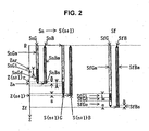
- Figure 2 is a detailed process explanatory diagram of a boring control method showing Embodiment 2.
- Figure 3 is a partially abbreviated explanatory diagram showing the variation characteristics of the main shaft torque rate corresponding to various processes in the boring control method corresponding to Claim 1, which illustrates Embodiment 3.
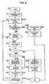
- Figure 4 is an outline process flow chart of the boring control method, showing Embodiment 4.
- Figure 5 is an abbreviated explanatory diagram of the apparatus using the boring control method corresponding to Claim 5, which illustrates Embodiment 5.
- Figure 6 is a partially abbreviated explanatory diagram showing the variation characteristics of the main shaft torque rate corresponding to various processes in the boring control method corresponding to Claim 5, which illustrates Embodiment 6.
- the boring control method corresponding to Claim 1 is a boring control method for a machine tool in which deep holes are automatically bored using the central control means (20) that performs a boring process by program control using a tool (1) as a cutting implement, while constantly detecting the load torque of the tool using torque detection means, and while checking the position of the tip end portion of the tool from a desired reference point (R) in the Z axis direction of the workpiece (10) to the hole-bottom (Zf) using a Z axis movement device (6); and this method is characterized by the fact that the boring process is executed so that:
- the boring control method corresponding to Claim 5 of the present invention is a boring control method for a machine tool which automatically bores deep holes using a central control means (20) that performs a boring process by program control using a tool (1) as a cutting implement while constantly detecting the load torque of the tool using torque detection means, and while checking the position of the tip end portion of the tool from a desired reference point (R) in the direction of Z axis of a workpiece (10) to the hole-bottom (Zf) using a Z axis movement device (6), characterized in that :
- the boring process can also be executed so that:
- the above-described return path step process (SnB) can be constructed from a return path step return process (SnBs) and a return path step movement process (SnBm).
- the working then shifts to the (n + 1)st step (Sn +
- the boring process of the final (f) step (Sf) can be executed so that:
- S TR approximately 16 ms
- the mean value (TR) is calculated and taken as the detected torque rate (TR)
- the torque rate (TR) is used here to express the
- the boring process of Embodiment 4 includes a withdrawal and spot-checking process which has a condition that a predetermined limiting step number does not exceeded N number of steps.
- the boring process is characterized by the following steps: namely, the process is initiated in a stage (P0); subsequently, in a reference point movement process of a stage (P1), the tool (1) is moved to a reference point (R); subsequently, in the forward path step cutting process (SnGd) of a stage (P2), boring cutting is initiated; subsequently, in the hole-bottom reaching process of a stage (P3), if the tool does not reach the hole-bottom (Zf), then go to (NO), and boring cutting is continued; then, in the torque limit process of a subsequent stage (P4), in cases where the load torque exceeds the torque limit value (TR LIM ) which is a specified predetermined threshold value, then go to (YES), and the feeding rate (F) of the tool is
- the boring control method corresponding to Claim 5 of the present invention is a boring control method for a machine tool in which a mist generator (2a) that produces a mist-form mixture of a cutting liquid and compressed air and that cools a tool with the minimum cutting liquid supply amount (Q) is provided in the main shaft unit (2) that holds and rotates a tool (1), the machine tool has a function that controls the mist generation conditions of the mist generator, and the machine tool comprises a device that controls the tool cooling conditions including variations over time during operation using the mist control means (5) basically disclosed in Japanese Patent Application Laid-Open (Kokai) No.
- Embodiment 5 is characterized by the fact that boring that bores deep holes automatically is performed using a central control means (20) that performs a boring process by program control while checking the position of the tip end portion of the tool from a desired reference point (R) in the Z axis direction of the workpiece (10) to a hole-bottom (Zf) using a Z axis movement device (6) via a movement control means (7), a torque detection means that detects the load torque of the tool detect the load current of a main shaft motor (which rotationally drives the main shaft unit) at a specified sampling time using a main shaft control means (8), and the mist control means that controls the mist generation conditions also controls the cutting liquid supply amount (Q) using a cutting liquid supply means (3) or also controls and ensures the air pressure (Pr) of the compressed air that is supplied using a compressed air supply means (4).
- a central control means (20) that performs a boring process by program control while checking the position of the tip end portion of the tool from a desired reference point (R)
- the tool cooling conditions are increased in stages as the steps increase. Accordingly, the limiting step number N was set at 4. Ordinarily, however, the number of the final step (Sf) of working is f ⁇ 2.
- the present invention is worked in the configurations described above and has the merits described below.
- the respective steps in the boring process are determined only by a specified predetermined torque limit value, working is continued up to this torque limit value, so that the working distance can be extended to the torque limit value while suppressing damage to the tool. Accordingly, the present invention has the merit of minimizing the total number of steps f. Furthermore, since each step is performed under fixed working conditions comprised of a specified pattern, the present invention has the merit of minimizing the working time.
- the present invention has the merit of suppressing extreme wear, damage and scratching of the tool, and also has the merit of being suitable for reutilization of the fool.
- a forward path step biting process (SnGi) can be set in the boring process at the time of initiation of working in each step, and these steps can be initiated with the feeding rate (F) set at a relatively low feeding rate, so that a rise in the load torque caused by unstable conditions resulting from wear, the dispersion of heat or the like during biting of the cutting tip of the tool can be suppressed. Accordingly, the working distance can be extended to the torque limit value, and an effect that suppresses damage to the tool can also be obtained.
- a forward path step withdrawal point process (SfGe) can be set in the boring process in the interval following the completion of working in the final step, so that this process can be performed with the feeding rate (F) reduced from the working feeding rate to the withdrawal point feeding rate, thus reducing working instability of the cutting tip of the tool during withdrawal point working so that a rise in the load torque can be suppressed. Accordingly, the working distance can be extended to the torque limit value, and an effect that suppresses damage to the tool can also be obtained.
- the tool cooling effect is increased in stages as the steps increase. Accordingly, the main shaft torque rate gradually decreases, and the total step number f is reduced compared to the method corresponding to Claim 1, so that an effect that suppresses damage to the tool is obtained.
Landscapes
- Engineering & Computer Science (AREA)
- Mechanical Engineering (AREA)
- Automatic Control Of Machine Tools (AREA)
- Drilling And Boring (AREA)
- Numerical Control (AREA)
- Electrical Discharge Machining, Electrochemical Machining, And Combined Machining (AREA)
- Earth Drilling (AREA)
- Nitrogen Condensed Heterocyclic Rings (AREA)
- Medicines Containing Material From Animals Or Micro-Organisms (AREA)
- Compounds Of Unknown Constitution (AREA)
Claims (6)
- Ein Bohrsteuerverfahren für ein unter Verwendung eines zentralen Steuermittels (20) automatisch tiefe Löcher bohrendes Maschinenwerkzeug, das ein Bohrverfahren mittels Programmsteuerung durchführt, während das Lastdrehmoment eines Werkzeugs (1) mittels eines Drehmomenterfassungsmittels konstant erfasst wird und während eine Stellung des Kopfendabschnitts des Werkzeugs unter Verwendung einer Z-Achsenbewegungsvorrichtung (6) von einem gewünschten Bezugspunkt (R) in einer Richtung der Z-Achse eines Werkstücks (10) zu einem Lochboden (Zf) geprüft wird, wobei das Bohrverfahren
dadurch gekennzeichnet
ist, dass in einem ersten Schritt (S1)
ein Vorwartswegschrittvorgang (S1G), welcher einen ersten einen Bohr-Schneidvorgang darstellenden Vorwärtswegschneidvorgang (S1Gd) umfasst, von dem Bezugspunkt (R) aus unter festen Betriebsbedingungen eingeleitet wird, die eine Hauptwellen-Drehzahl (S), die eine Drehzahl des Werkzeugs ist, und eine Vorschubgeschwindigkeit (F) des Werkzeugs umfasst;
mit Hilfe des Drehmomenterfassungsmittels, welches das Lastdrehmoment des Werkzeugs (1) erfasst, ein Arbeitsstrom eines Hauptwellenmotors fortlaufend erfasst wird, so dass der Arbeitsstrom bei einer vorgegebenen Probenahmezeit (STR) und bei einer vorgegebenen Lesefrequenz (Ns) abgelesen werden kann, so dass ein Mittelwert errechnet und als ein erfasster Drehmomentwert (TR) genommen wird, und der Drehmomentwert (TR) mit einem Drehmoment-Grenzwert (TRLIM) innerhalb einer vorgegebenen Erfassungszeit (ΔT) verglichen wird;
die Vorschubgeschwindigkeit (F) des Werkzeugs angehalten wird, sobald der Drehmomentwert (TR) den Drehmoment-Grenzwert (TRUM) überschreitet, der einen bestimmten vorgegebenen Schwellenwert darstellt, so dass eine Position, bei der das Werkzeug angehalten wird, als ein erster geschnittener Lochboden (Z1) genommen wird, und
das Werkzeug unter festen Rückziehbedingungen in einem Rückwärtswegschrittverfahren (S1B) auf den Bezugspunkt (R) zurückgezogen wird; und anschließend in einem zweiten Schritt (S2) das Werkzeug von dem Bezugspunkt (R) in einem Vorwärtswegschritt-Bewegungsvorgang (S2Gm) eines Vorwärtswegschritt-Vorgang (S2G) in die Nähe des ersten geschnittenen Lochbodens (Z1) bewegt wird und einen zweiten Vorwärtswegschritt-Schneidvorgang (S2Gd), der ein Bohr-Schneidvorgang ist, unter den vorgegebenen Betriebsbedingungen eingeleitet wird,
mit Hilfe des Drehmomenterfassungsmittels, welches das Lastdrehmoment des Werkzeugs (1) erfasst, ein Arbeitsstrom eines Hauptwollenmotors fortlaufend erfasst wird, so dass der Arbeitsstrom bei einer vorgegebenen Probenahmezeit (STR) und bei einer vorgegebenen Lesefrequenz (NS) abgelesen werden kann, so dass ein Mittelwert errechnet und als ein erfasster Drehmomentwert (TR) genommen wird, und der Drehmomentwert (TR) mit einem Drehmoment-Grenzwert (TRUM) innerhalb einer vorgegebenen Erfassungszeit (ΔT) verglichen wird;
die Vorschubgeschwindigkeit (F) des Werkzeugs angehalten wird, sobald der Lastdrehzahlwert (TR) den Lastdrehzahl-Grenzwert (TRUM) überschreitet, so dass eine Position, bei der das Werkzeug angehalten wird, als ein zweiter gefräster Lochboden (Z2) genommen wird, und das Werkzeug unter den vorgegebenen Rückziehbedingungen auf den Bezugspunkt (R) in einem Rückwärtswegschrittverfahren (S2B) zurückgezogen wird, und
ein solcher Schritt (Sn) wiederholt wird; und
in einem letzten (f) Schritt (Sf)
das Werkzeug den Lochboden (Zf) erreicht und die Vorschubgeschwindigkeit (F) des Werkzeugs in einem Vorwärtswegschritt-Schneidverfahren (SfGd) abgeschaltet wird, und
das Werkzeug unter den vorgegebenen Rückziehbedingungen in einem Rückwärtswegschrittverfahren (SfB) zurückgezogen wird und das Bohrverfahren beendet wird. - Das Bohrverfahren nach Anspruch 1,
dadurch gekennzeichnet,
dass eine Bedingung aufgestellt wird, wonach eine Schrittzahl f eine vorgegebene Grenzschrittzahl N nicht überschreitet, und
ein Rückzieh- und Stichprobenvorgang bei dem Bohrverfahren vorgesehen ist, so dass spätestens, wenn die Schrittzahl f N erreicht und das Lastdrehmoment den Drehmomentgrenzwert überschreitet, die Vorschubgeschwindigkeit (F) des Werkzeugs angehalten wird, der Bohrvorgang unterbrochen wird und das Werkzeug zurückgezogen wird und ein Schneidkopf des Werkzeugs überprüft wird. - Das Bohrsteuerverfahren nach Anspruch 1 oder 2,
dadurch gekennzeichnet,
dass der jeweils wiederholte Schritt (Sn) einen Vorwärtswegschritt-Angreifvorgang (SfGi) zu Beginn eines Arbeitsvorgangs einschließt und der letzte (f) Schritt (Sf) einen Vorwärtswegschritt-Angreifvorgang (SfGi) zu Beginn eines Arbeitsvorgangs einschließt. - Das Bohrsteuerverfahren nach einem der Ansprüche 1, 2 und 3,
dadurch gekennzeichnet,
dass der letzte (f) Schritt (Sf) einen Vorwärtswegschritt-Rückziehpunktvorgang (SfGe) umfasst, bei dem, wenn eine Werkzeug-Schneidspitze sich einer Position eines Lochboden-Ziels auf eine bestimmte Entfernung nähert, ein Heranarbeiten an das Lochboden-Ziel durchgeführt wird, wobei die Vorschubgeschwindigkeit (F) von einer Arbeitsvorschubgeschwindigkeit auf eine Rückführpunkt-Vorschubgeschwindigkeit herabgesetzt wird. - Ein Bohrsteuerverfahren nach Anspruch 1,
dadurch gekennzeichnet,
dass ein Nebelgenerator (2a), der ein eine Schneidflüssigkeit und Druckluft umfassendes nebelförmiges Gemisch erzeugt und der das Werkzeug bei minimaler Schneidflüssigkeitszufuhrmenge (Q) bis zur Schneidspitze zwangsläufig kühlt, im Innern einer das Werkzeug haltenden und drehenden Hauptwelleneinheit (2) angeordnet ist, und
dass Werkzeugkühlungsbedingungen einschließlich Abweichungen während der Gesamtzeit des Betriebs unter Verwendung eines Nebelsteuerungsmittels (5) gesteuert werden, das die Nebelerzeugungsbedingungen des Nebelgenerators steuert. - Das Bohrsteuerverfahren nach Anspruch 5,
dadurch gekennzeichnet,
dass eine Bedingung eingestellt wird, dass eine Schrittzahl f eine vorgegebene Grenzschrittzahl N nicht überschreitet, und
bei dem Bohrvorgang ein Rückzieh- und Stichprobenvorgang vorgesehen ist, so dass spätestens, wenn die Schrittzahl f N erreicht und das Lastdrehmoment den Drehmomentgrenzwert überschreitet, die Vorschubgeschwindigkeit (F) des Werkzeugs angehalten wird, der Bohrvorgang unterbrochen wird und das Werkzeug zurückgezogen und ein Schneidkopf des Werkzeugs überprüft wird.
Applications Claiming Priority (3)
| Application Number | Priority Date | Filing Date | Title |
|---|---|---|---|
| JP2002158851A JP3533650B2 (ja) | 2002-05-31 | 2002-05-31 | 穴開け加工制御方法 |
| JP2002158851 | 2002-05-31 | ||
| PCT/JP2003/006427 WO2003101651A1 (fr) | 2002-05-31 | 2003-05-22 | Procede de controle d'alesage |
Publications (3)
| Publication Number | Publication Date |
|---|---|
| EP1514625A1 EP1514625A1 (de) | 2005-03-16 |
| EP1514625A4 EP1514625A4 (de) | 2008-07-30 |
| EP1514625B1 true EP1514625B1 (de) | 2010-09-15 |
Family
ID=29706496
Family Applications (1)
| Application Number | Title | Priority Date | Filing Date |
|---|---|---|---|
| EP03730592A Expired - Lifetime EP1514625B1 (de) | 2002-05-31 | 2003-05-22 | Bohrsteuerverfahren |
Country Status (7)
| Country | Link |
|---|---|
| US (1) | US7172034B2 (de) |
| EP (1) | EP1514625B1 (de) |
| JP (1) | JP3533650B2 (de) |
| KR (1) | KR100734200B1 (de) |
| AT (1) | ATE481196T1 (de) |
| DE (1) | DE60334214D1 (de) |
| WO (1) | WO2003101651A1 (de) |
Families Citing this family (18)
| Publication number | Priority date | Publication date | Assignee | Title |
|---|---|---|---|---|
| DE102006016448A1 (de) | 2006-04-07 | 2007-10-11 | Robert Bosch Gmbh | Elektrowerkzeugmaschine und Verfahren zum Betreiben derselben |
| KR100870190B1 (ko) * | 2008-01-21 | 2008-11-24 | (주)현화 | 내부에 공간을 형성하여 3단계 지압효과를 발휘하는신발바닥창 |
| US8424426B2 (en) * | 2008-04-11 | 2013-04-23 | Honda Motor Co., Ltd. | Method and device for boring non-round hole |
| JP5278758B2 (ja) * | 2009-05-15 | 2013-09-04 | 本田技研工業株式会社 | カム駆動装置及び加工方法 |
| JP5622463B2 (ja) | 2010-07-09 | 2014-11-12 | 株式会社スギノマシン | 穴あけ加工制御方法および穴あけ加工装置 |
| CN101954570B (zh) * | 2010-08-11 | 2012-02-22 | 云顶汽车部件股份有限公司 | 用两阶式刀杆加工倒沉孔及倒角的加工方法 |
| JP2013184266A (ja) * | 2012-03-09 | 2013-09-19 | Hitachi Koki Co Ltd | 電動工具及び電動工具システム |
| CN103111650A (zh) * | 2013-01-25 | 2013-05-22 | 西北工业大学 | 一种可倾斜主轴数控铣床钻孔加工方法 |
| KR102092968B1 (ko) * | 2013-06-10 | 2020-03-24 | 두산공작기계 주식회사 | 회전 절삭공구의 초기 축방향 절삭 깊이 설정방법 및 제어장치 |
| DE102013224759A1 (de) * | 2013-12-03 | 2015-06-03 | Robert Bosch Gmbh | Werkzeugmaschinenvorrichtung |
| CN106457498B (zh) * | 2014-05-26 | 2019-04-23 | 诺瓦特公司 | 工件加工的方法、系统和存储介质 |
| ITUB20152150A1 (it) * | 2015-07-14 | 2017-01-14 | Mep S P A | procedimento e dispositivo per gestione del tagliente, nelle macchine utensili per il taglio dei metalli |
| CN105500111A (zh) * | 2015-12-25 | 2016-04-20 | 鼎奇(天津)主轴科技有限公司 | 一种机床主轴空载摩擦力矩测试方法及控制系统 |
| CA3038618A1 (en) * | 2016-09-28 | 2018-04-05 | Chetocorporation, S.A. | System and method for operating a cutting machine |
| JP6871221B2 (ja) | 2018-11-14 | 2021-05-12 | ファナック株式会社 | 数値制御装置 |
| JP6966412B2 (ja) | 2018-11-15 | 2021-11-17 | ファナック株式会社 | 数値制御装置 |
| CN112936101B (zh) * | 2021-01-29 | 2022-11-01 | 天津中屹铭科技有限公司 | 一种应用于自动化打磨切割设备的柔性控制方法 |
| EP4063049A1 (de) * | 2021-03-24 | 2022-09-28 | Airbus Operations, S.L.U. | Vorrichtung und verfahren zum bohren mit automatischer bohrparameteranpassung |
Family Cites Families (15)
| Publication number | Priority date | Publication date | Assignee | Title |
|---|---|---|---|---|
| JPS5775712A (en) * | 1980-10-30 | 1982-05-12 | Brother Ind Ltd | Borer equipped with step feed function |
| US4536849A (en) * | 1982-09-08 | 1985-08-20 | Cincinnati Milacron Inc. | Machine operation monitor |
| US4612831A (en) * | 1985-02-19 | 1986-09-23 | Lehmkuhl Robert A | Automatic boring tool |
| JPS62246408A (ja) * | 1986-04-18 | 1987-10-27 | Fanuc Ltd | 深穴ドリルサイクル制御方式 |
| JPH01146642A (ja) * | 1987-12-03 | 1989-06-08 | Fanuc Ltd | 切削工具の停止制御装置 |
| US4944643A (en) * | 1989-05-08 | 1990-07-31 | Lehmkuhl Robert A | Torque thrust and surface sensing device |
| JPH03190612A (ja) * | 1989-12-15 | 1991-08-20 | Nippon Pneumatic Mfg Co Ltd | 穴明け加工方法および装置 |
| JPH03281113A (ja) * | 1990-03-30 | 1991-12-11 | Babcock Hitachi Kk | マシンニングセンタ |
| US5378091A (en) * | 1992-06-17 | 1995-01-03 | Makino Milling Machine Co., Ltd. | Method and apparatus for machining a workpiece |
| JP3256302B2 (ja) * | 1992-11-26 | 2002-02-12 | 株式会社日平トヤマ | 加工機の工具破損防止装置 |
| US5349337A (en) * | 1992-12-15 | 1994-09-20 | Eoa Systems, Inc. | Apparatus and method for controlling peck drilling |
| JP3363958B2 (ja) * | 1993-07-13 | 2003-01-08 | ファナック株式会社 | ドリル加工方式 |
| DE19632401A1 (de) * | 1996-08-12 | 1998-02-19 | Delmag Maschinenfabrik | Bohrgerät |
| JP3603051B2 (ja) * | 2001-06-22 | 2004-12-15 | 東芝機械株式会社 | 数値制御工作機械の送り速度・加速度制御方法および数値制御装置 |
| FI118306B (fi) * | 2001-12-07 | 2007-09-28 | Sandvik Tamrock Oy | Menetelmä ja laitteisto kallionporauslaitteen toiminnan ohjaamiseksi |
-
2002
- 2002-05-31 JP JP2002158851A patent/JP3533650B2/ja not_active Expired - Fee Related
-
2003
- 2003-05-22 WO PCT/JP2003/006427 patent/WO2003101651A1/ja not_active Ceased
- 2003-05-22 US US10/516,214 patent/US7172034B2/en not_active Expired - Lifetime
- 2003-05-22 DE DE60334214T patent/DE60334214D1/de not_active Expired - Lifetime
- 2003-05-22 KR KR1020047017903A patent/KR100734200B1/ko not_active Expired - Fee Related
- 2003-05-22 EP EP03730592A patent/EP1514625B1/de not_active Expired - Lifetime
- 2003-05-22 AT AT03730592T patent/ATE481196T1/de not_active IP Right Cessation
Also Published As
| Publication number | Publication date |
|---|---|
| DE60334214D1 (de) | 2010-10-28 |
| US20050226692A1 (en) | 2005-10-13 |
| WO2003101651A1 (fr) | 2003-12-11 |
| KR100734200B1 (ko) | 2007-07-02 |
| EP1514625A1 (de) | 2005-03-16 |
| US7172034B2 (en) | 2007-02-06 |
| KR20050016868A (ko) | 2005-02-21 |
| JP2004001120A (ja) | 2004-01-08 |
| JP3533650B2 (ja) | 2004-05-31 |
| ATE481196T1 (de) | 2010-10-15 |
| EP1514625A4 (de) | 2008-07-30 |
Similar Documents
| Publication | Publication Date | Title |
|---|---|---|
| EP1514625B1 (de) | Bohrsteuerverfahren | |
| CN103153508B (zh) | 打孔加工控制方法以及打孔加工装置 | |
| US7092786B2 (en) | Tool damage/abnormality detecting device | |
| EP1407853B1 (de) | Vorrichtung zur Überwachung oder Vermeidung eines Werkzeugbruchs | |
| US6665579B2 (en) | Control method for bar material feeder of NC lathe and NC lathe | |
| KR101942002B1 (ko) | 지능형 절삭유 분사장치 및 이의 분사방법 | |
| CN107931855B (zh) | 切管机卡管抑制方法及激光切管机 | |
| CN104656475A (zh) | 在非常停止时保护刀具和被加工物的电动机控制装置 | |
| CN101281400A (zh) | 一种数控深孔钻床双重过载保护方法 | |
| US20130134238A1 (en) | Cutting fluid ejection apparatus | |
| US5011345A (en) | Contour machining method and apparatus for printed circuit board | |
| US4221141A (en) | Method and apparatus for feeding bar stock to a machine tool | |
| JP3117939U (ja) | タッピング装置 | |
| WO2022009797A1 (ja) | 数値制御装置及び制御方法 | |
| JP3636895B2 (ja) | 主軸移動型立形工作機械用の棒状工作物供給装置および主軸移動型立形工作機械における棒状工作物供給方法 | |
| JP7523930B2 (ja) | 棒材供給装置、棒材供給装置を備えた工作機械、棒材供給装置の制御方法 | |
| JP3327133B2 (ja) | クーラントの流出量制御方法および流出量制御装置 | |
| JP4487593B2 (ja) | ドリル加工機能付き工作機械 | |
| JPS63150137A (ja) | 適応制御装置 | |
| KR100337381B1 (ko) | 수동선반의 바이트 파손방지 방법 | |
| JPH04240011A (ja) | 穴開け加工方式 | |
| US20240310812A1 (en) | Method for operating a machine tool and/or production machine | |
| JPH09234524A (ja) | パイプ加工機におけるワ−クのセット状態の制御方法 | |
| JP2022072601A (ja) | 工作機械 | |
| JPH07185920A (ja) | ワークの穴明け切断加工方法及び同加工ライン装置 |
Legal Events
| Date | Code | Title | Description |
|---|---|---|---|
| PUAI | Public reference made under article 153(3) epc to a published international application that has entered the european phase |
Free format text: ORIGINAL CODE: 0009012 |
|
| 17P | Request for examination filed |
Effective date: 20041213 |
|
| AK | Designated contracting states |
Kind code of ref document: A1 Designated state(s): AT BE BG CH CY CZ DE DK EE ES FI FR GB GR HU IE IT LI LU MC NL PT RO SE SI SK TR |
|
| AX | Request for extension of the european patent |
Extension state: AL LT LV MK |
|
| DAX | Request for extension of the european patent (deleted) | ||
| A4 | Supplementary search report drawn up and despatched |
Effective date: 20080702 |
|
| 17Q | First examination report despatched |
Effective date: 20081027 |
|
| GRAP | Despatch of communication of intention to grant a patent |
Free format text: ORIGINAL CODE: EPIDOSNIGR1 |
|
| GRAS | Grant fee paid |
Free format text: ORIGINAL CODE: EPIDOSNIGR3 |
|
| GRAA | (expected) grant |
Free format text: ORIGINAL CODE: 0009210 |
|
| AK | Designated contracting states |
Kind code of ref document: B1 Designated state(s): AT BE BG CH CY CZ DE DK EE ES FI FR GB GR HU IE IT LI LU MC NL PT RO SE SI SK TR |
|
| REG | Reference to a national code |
Ref country code: GB Ref legal event code: FG4D Ref country code: CH Ref legal event code: EP |
|
| REG | Reference to a national code |
Ref country code: IE Ref legal event code: FG4D |
|
| REF | Corresponds to: |
Ref document number: 60334214 Country of ref document: DE Date of ref document: 20101028 Kind code of ref document: P |
|
| REG | Reference to a national code |
Ref country code: NL Ref legal event code: VDEP Effective date: 20100915 |
|
| PG25 | Lapsed in a contracting state [announced via postgrant information from national office to epo] |
Ref country code: FI Free format text: LAPSE BECAUSE OF FAILURE TO SUBMIT A TRANSLATION OF THE DESCRIPTION OR TO PAY THE FEE WITHIN THE PRESCRIBED TIME-LIMIT Effective date: 20100915 Ref country code: AT Free format text: LAPSE BECAUSE OF FAILURE TO SUBMIT A TRANSLATION OF THE DESCRIPTION OR TO PAY THE FEE WITHIN THE PRESCRIBED TIME-LIMIT Effective date: 20100915 |
|
| PG25 | Lapsed in a contracting state [announced via postgrant information from national office to epo] |
Ref country code: SI Free format text: LAPSE BECAUSE OF FAILURE TO SUBMIT A TRANSLATION OF THE DESCRIPTION OR TO PAY THE FEE WITHIN THE PRESCRIBED TIME-LIMIT Effective date: 20100915 Ref country code: CY Free format text: LAPSE BECAUSE OF FAILURE TO SUBMIT A TRANSLATION OF THE DESCRIPTION OR TO PAY THE FEE WITHIN THE PRESCRIBED TIME-LIMIT Effective date: 20100915 |
|
| PG25 | Lapsed in a contracting state [announced via postgrant information from national office to epo] |
Ref country code: SE Free format text: LAPSE BECAUSE OF FAILURE TO SUBMIT A TRANSLATION OF THE DESCRIPTION OR TO PAY THE FEE WITHIN THE PRESCRIBED TIME-LIMIT Effective date: 20100915 Ref country code: GR Free format text: LAPSE BECAUSE OF FAILURE TO SUBMIT A TRANSLATION OF THE DESCRIPTION OR TO PAY THE FEE WITHIN THE PRESCRIBED TIME-LIMIT Effective date: 20101216 |
|
| PG25 | Lapsed in a contracting state [announced via postgrant information from national office to epo] |
Ref country code: SK Free format text: LAPSE BECAUSE OF FAILURE TO SUBMIT A TRANSLATION OF THE DESCRIPTION OR TO PAY THE FEE WITHIN THE PRESCRIBED TIME-LIMIT Effective date: 20100915 Ref country code: CZ Free format text: LAPSE BECAUSE OF FAILURE TO SUBMIT A TRANSLATION OF THE DESCRIPTION OR TO PAY THE FEE WITHIN THE PRESCRIBED TIME-LIMIT Effective date: 20100915 Ref country code: RO Free format text: LAPSE BECAUSE OF FAILURE TO SUBMIT A TRANSLATION OF THE DESCRIPTION OR TO PAY THE FEE WITHIN THE PRESCRIBED TIME-LIMIT Effective date: 20100915 Ref country code: EE Free format text: LAPSE BECAUSE OF FAILURE TO SUBMIT A TRANSLATION OF THE DESCRIPTION OR TO PAY THE FEE WITHIN THE PRESCRIBED TIME-LIMIT Effective date: 20100915 Ref country code: PT Free format text: LAPSE BECAUSE OF FAILURE TO SUBMIT A TRANSLATION OF THE DESCRIPTION OR TO PAY THE FEE WITHIN THE PRESCRIBED TIME-LIMIT Effective date: 20110117 Ref country code: NL Free format text: LAPSE BECAUSE OF FAILURE TO SUBMIT A TRANSLATION OF THE DESCRIPTION OR TO PAY THE FEE WITHIN THE PRESCRIBED TIME-LIMIT Effective date: 20100915 |
|
| PG25 | Lapsed in a contracting state [announced via postgrant information from national office to epo] |
Ref country code: BE Free format text: LAPSE BECAUSE OF FAILURE TO SUBMIT A TRANSLATION OF THE DESCRIPTION OR TO PAY THE FEE WITHIN THE PRESCRIBED TIME-LIMIT Effective date: 20100915 Ref country code: ES Free format text: LAPSE BECAUSE OF FAILURE TO SUBMIT A TRANSLATION OF THE DESCRIPTION OR TO PAY THE FEE WITHIN THE PRESCRIBED TIME-LIMIT Effective date: 20101226 |
|
| PLBE | No opposition filed within time limit |
Free format text: ORIGINAL CODE: 0009261 |
|
| STAA | Information on the status of an ep patent application or granted ep patent |
Free format text: STATUS: NO OPPOSITION FILED WITHIN TIME LIMIT |
|
| 26N | No opposition filed |
Effective date: 20110616 |
|
| PG25 | Lapsed in a contracting state [announced via postgrant information from national office to epo] |
Ref country code: DK Free format text: LAPSE BECAUSE OF FAILURE TO SUBMIT A TRANSLATION OF THE DESCRIPTION OR TO PAY THE FEE WITHIN THE PRESCRIBED TIME-LIMIT Effective date: 20100915 |
|
| REG | Reference to a national code |
Ref country code: DE Ref legal event code: R097 Ref document number: 60334214 Country of ref document: DE Effective date: 20110616 |
|
| PG25 | Lapsed in a contracting state [announced via postgrant information from national office to epo] |
Ref country code: MC Free format text: LAPSE BECAUSE OF NON-PAYMENT OF DUE FEES Effective date: 20110531 |
|
| REG | Reference to a national code |
Ref country code: CH Ref legal event code: PL |
|
| GBPC | Gb: european patent ceased through non-payment of renewal fee |
Effective date: 20110522 |
|
| PG25 | Lapsed in a contracting state [announced via postgrant information from national office to epo] |
Ref country code: LI Free format text: LAPSE BECAUSE OF NON-PAYMENT OF DUE FEES Effective date: 20110531 Ref country code: CH Free format text: LAPSE BECAUSE OF NON-PAYMENT OF DUE FEES Effective date: 20110531 |
|
| REG | Reference to a national code |
Ref country code: IE Ref legal event code: MM4A |
|
| PG25 | Lapsed in a contracting state [announced via postgrant information from national office to epo] |
Ref country code: IE Free format text: LAPSE BECAUSE OF NON-PAYMENT OF DUE FEES Effective date: 20110522 |
|
| PG25 | Lapsed in a contracting state [announced via postgrant information from national office to epo] |
Ref country code: GB Free format text: LAPSE BECAUSE OF NON-PAYMENT OF DUE FEES Effective date: 20110522 |
|
| PG25 | Lapsed in a contracting state [announced via postgrant information from national office to epo] |
Ref country code: LU Free format text: LAPSE BECAUSE OF NON-PAYMENT OF DUE FEES Effective date: 20110522 |
|
| PG25 | Lapsed in a contracting state [announced via postgrant information from national office to epo] |
Ref country code: BG Free format text: LAPSE BECAUSE OF FAILURE TO SUBMIT A TRANSLATION OF THE DESCRIPTION OR TO PAY THE FEE WITHIN THE PRESCRIBED TIME-LIMIT Effective date: 20101215 Ref country code: TR Free format text: LAPSE BECAUSE OF FAILURE TO SUBMIT A TRANSLATION OF THE DESCRIPTION OR TO PAY THE FEE WITHIN THE PRESCRIBED TIME-LIMIT Effective date: 20100915 |
|
| PG25 | Lapsed in a contracting state [announced via postgrant information from national office to epo] |
Ref country code: HU Free format text: LAPSE BECAUSE OF FAILURE TO SUBMIT A TRANSLATION OF THE DESCRIPTION OR TO PAY THE FEE WITHIN THE PRESCRIBED TIME-LIMIT Effective date: 20100915 |
|
| REG | Reference to a national code |
Ref country code: FR Ref legal event code: PLFP Year of fee payment: 14 |
|
| REG | Reference to a national code |
Ref country code: FR Ref legal event code: PLFP Year of fee payment: 15 |
|
| REG | Reference to a national code |
Ref country code: FR Ref legal event code: PLFP Year of fee payment: 16 |
|
| REG | Reference to a national code |
Ref country code: DE Ref legal event code: R082 Ref document number: 60334214 Country of ref document: DE |
|
| PGFP | Annual fee paid to national office [announced via postgrant information from national office to epo] |
Ref country code: FR Payment date: 20200421 Year of fee payment: 18 Ref country code: DE Payment date: 20200417 Year of fee payment: 18 |
|
| PGFP | Annual fee paid to national office [announced via postgrant information from national office to epo] |
Ref country code: IT Payment date: 20200519 Year of fee payment: 18 |
|
| REG | Reference to a national code |
Ref country code: DE Ref legal event code: R119 Ref document number: 60334214 Country of ref document: DE |
|
| PG25 | Lapsed in a contracting state [announced via postgrant information from national office to epo] |
Ref country code: DE Free format text: LAPSE BECAUSE OF NON-PAYMENT OF DUE FEES Effective date: 20211201 |
|
| PG25 | Lapsed in a contracting state [announced via postgrant information from national office to epo] |
Ref country code: FR Free format text: LAPSE BECAUSE OF NON-PAYMENT OF DUE FEES Effective date: 20210531 |
|
| PG25 | Lapsed in a contracting state [announced via postgrant information from national office to epo] |
Ref country code: IT Free format text: LAPSE BECAUSE OF NON-PAYMENT OF DUE FEES Effective date: 20200522 |
|
| PG25 | Lapsed in a contracting state [announced via postgrant information from national office to epo] |
Ref country code: IT Free format text: LAPSE BECAUSE OF NON-PAYMENT OF DUE FEES Effective date: 20210522 |