EP1514603B1 - Device for treating material - Google Patents
Device for treating material Download PDFInfo
- Publication number
- EP1514603B1 EP1514603B1 EP04021326A EP04021326A EP1514603B1 EP 1514603 B1 EP1514603 B1 EP 1514603B1 EP 04021326 A EP04021326 A EP 04021326A EP 04021326 A EP04021326 A EP 04021326A EP 1514603 B1 EP1514603 B1 EP 1514603B1
- Authority
- EP
- European Patent Office
- Prior art keywords
- crushing
- coarse
- recesses
- comminution
- chisels
- Prior art date
- Legal status (The legal status is an assumption and is not a legal conclusion. Google has not performed a legal analysis and makes no representation as to the accuracy of the status listed.)
- Not-in-force
Links
Images

Classifications
-
- B—PERFORMING OPERATIONS; TRANSPORTING
- B02—CRUSHING, PULVERISING, OR DISINTEGRATING; PREPARATORY TREATMENT OF GRAIN FOR MILLING
- B02C—CRUSHING, PULVERISING, OR DISINTEGRATING IN GENERAL; MILLING GRAIN
- B02C4/00—Crushing or disintegrating by roller mills
- B02C4/28—Details
- B02C4/30—Shape or construction of rollers
-
- B—PERFORMING OPERATIONS; TRANSPORTING
- B02—CRUSHING, PULVERISING, OR DISINTEGRATING; PREPARATORY TREATMENT OF GRAIN FOR MILLING
- B02C—CRUSHING, PULVERISING, OR DISINTEGRATING IN GENERAL; MILLING GRAIN
- B02C13/00—Disintegrating by mills having rotary beater elements ; Hammer mills
- B02C13/20—Disintegrating by mills having rotary beater elements ; Hammer mills with two or more co-operating rotors
-
- B—PERFORMING OPERATIONS; TRANSPORTING
- B02—CRUSHING, PULVERISING, OR DISINTEGRATING; PREPARATORY TREATMENT OF GRAIN FOR MILLING
- B02C—CRUSHING, PULVERISING, OR DISINTEGRATING IN GENERAL; MILLING GRAIN
- B02C18/00—Disintegrating by knives or other cutting or tearing members which chop material into fragments
- B02C18/06—Disintegrating by knives or other cutting or tearing members which chop material into fragments with rotating knives
- B02C18/14—Disintegrating by knives or other cutting or tearing members which chop material into fragments with rotating knives within horizontal containers
- B02C18/142—Disintegrating by knives or other cutting or tearing members which chop material into fragments with rotating knives within horizontal containers with two or more inter-engaging rotatable cutter assemblies
-
- B—PERFORMING OPERATIONS; TRANSPORTING
- B02—CRUSHING, PULVERISING, OR DISINTEGRATING; PREPARATORY TREATMENT OF GRAIN FOR MILLING
- B02C—CRUSHING, PULVERISING, OR DISINTEGRATING IN GENERAL; MILLING GRAIN
- B02C18/00—Disintegrating by knives or other cutting or tearing members which chop material into fragments
- B02C18/06—Disintegrating by knives or other cutting or tearing members which chop material into fragments with rotating knives
- B02C18/16—Details
- B02C18/18—Knives; Mountings thereof
- B02C18/182—Disc-shaped knives
-
- B—PERFORMING OPERATIONS; TRANSPORTING
- B02—CRUSHING, PULVERISING, OR DISINTEGRATING; PREPARATORY TREATMENT OF GRAIN FOR MILLING
- B02C—CRUSHING, PULVERISING, OR DISINTEGRATING IN GENERAL; MILLING GRAIN
- B02C21/00—Disintegrating plant with or without drying of the material
-
- B—PERFORMING OPERATIONS; TRANSPORTING
- B02—CRUSHING, PULVERISING, OR DISINTEGRATING; PREPARATORY TREATMENT OF GRAIN FOR MILLING
- B02C—CRUSHING, PULVERISING, OR DISINTEGRATING IN GENERAL; MILLING GRAIN
- B02C23/00—Auxiliary methods or auxiliary devices or accessories specially adapted for crushing or disintegrating not provided for in preceding groups or not specially adapted to apparatus covered by a single preceding group
- B02C23/02—Feeding devices
-
- B—PERFORMING OPERATIONS; TRANSPORTING
- B02—CRUSHING, PULVERISING, OR DISINTEGRATING; PREPARATORY TREATMENT OF GRAIN FOR MILLING
- B02C—CRUSHING, PULVERISING, OR DISINTEGRATING IN GENERAL; MILLING GRAIN
- B02C4/00—Crushing or disintegrating by roller mills
- B02C4/02—Crushing or disintegrating by roller mills with two or more rollers
- B02C4/08—Crushing or disintegrating by roller mills with two or more rollers with co-operating corrugated or toothed crushing-rollers
-
- B—PERFORMING OPERATIONS; TRANSPORTING
- B02—CRUSHING, PULVERISING, OR DISINTEGRATING; PREPARATORY TREATMENT OF GRAIN FOR MILLING
- B02C—CRUSHING, PULVERISING, OR DISINTEGRATING IN GENERAL; MILLING GRAIN
- B02C4/00—Crushing or disintegrating by roller mills
- B02C4/10—Crushing or disintegrating by roller mills with a roller co-operating with a stationary member
Definitions
- the invention relates to a device for the treatment of excavated earth, sludges, garbage or other material that may contain contaminants.
- the shredding device is suitable for example for mineral materials, such as excavated soil, coarse gravel, stones or other material. It is a fine comminution possible, with particle sizes of 10 mm to 60 mm can be achieved.
- a device for processing mineral material, in particular excavated soil known, which may also contain brittle, coarse-grained ingredients.
- For comminution serves a splitting mechanism with two counter-rotating shafts, which sit on sharpened chisels. These serve to burst the coarse ingredients to cause comminution. This can be done in the presence of cohesive material, ie clay or clay-containing material.
- the coarse components are comminuted to a particle size of about 60 mm.
- the flour and fine grain content is low.
- the material thus produced is in principle suitable for re-installation as a result of the comminution of the coarse components. For example, for filling excavated soil pits, such as pits or trenches. However, it is necessary to add to the material to be treated an additive, such as cement, ash, stone meal, granules, fibers, wood chips, wood flour, suspensions, such as lime suspensions, bentonites or dense suspensions.
- an additive such as cement, ash, stone meal, granules, fibers, wood chips, wood flour, suspensions, such as lime suspensions, bentonites or dense suspensions.
- the material to be processed of indefinite shape for example, in the presence of lumpy coarse material subjected to a crushing process in which the lumpy coarse material is at least partially crushed and mixed with the material.
- the comminution is preferably set so that the lumpy coarse material bindable components releases.
- the process is driven in such a way that the bondable constituents which are generally fine constituents produced act as an aggregate, so that the treatment can take place without the addition of additional additives, such as cement, lime, fibers, chips and the like.
- additional additives such as cement, lime, fibers, chips and the like.
- This fine fraction is mixed during the crushing process in the loamy-clay component and then acts as an aggregate.
- the grinding of the lumpy coarse material can also be done separately.
- an aggregate having binding ability e.g., cement, lime, dusts, seeds, nuts / nutshells.
- the ground coarse constituents above all have water-binding capacity and thus increase the stability and load-bearing capacity of the treated material, when e.g. is used for filling excavated ditches without provoking an unhealthy after hardening of the material.
- the carrying capacity of the material to be treated is merely brought about by the addition of cement, the material cures so strongly that a later re-opening of the trench becomes difficult.
- the invention makes it possible in many cases to reduce the need for additional additives below 0.5 wt.%. Often, additional aggregate is completely unnecessary. With water contents of up to 30% and stone content of approx. 50%, it is usually possible to completely dispense with additional binder.
- the rock flour produced during the comminution process acts like an aggregate.
- the rock flour may show different binding properties depending on the chemical nature. For example, it may be water absorbent. In addition, it can have a strengthening effect through ion exchange processes. It may further show a pozzolanic binding effect. It can also act as a binding agent by absorbing water, for example when it contains anhydride components. In addition, it can form hydrate bonds that can come about through microcrystal growth. This is particularly the case when used as coarse material concrete or other construction waste be used. As a rule, such construction waste still contains unbound components and thus a residual binding capacity. In addition, recrystallization operations may result in re-setting after fine milling.
- the material can also be adjusted to be dry enough to be sieved. It turns out that still existing stones can be screened out without significant adhesion of clay or the like.
- disks with chisels are provided on at least one shaft, wherein these disks are asymmetrical.
- a receiving space for coarse components is formed, wherein a disk, when carrying two chisels, has a small and a large receiving space. This ensures that on the one hand very large, coarse chunks can be crushed, while on the other hand prevents larger amounts of average grain between unobstructed slices fall through each other.
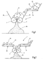
- FIG. 1 a crusher 1 is illustrated which serves as a crushing, milling and trash removing device. It has, for example, two counter-rotating shafts 2, 3 with crushing tools seated thereon.
- the crushing tools for example, according to DE 101 11 305 A1 or according to DE 202 14 956 U1 be educated. Notwithstanding these documents, however, the crushing tools are adjusted so that not only a grain size of about 60 mm grain size but at least a portion of the coarse components is much more crushed. This can be achieved in different ways.
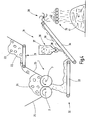
- FIG. 3 directed. This illustrates the waves 2, 3 in perspective view. They carry axially offset from each other discs 4, 5, which are provided at their periphery with recesses. In these recesses breakers 6, 7 can sit.
- the recesses may be formed with each other the same or different.
- the refracting bits 6, 7 preferably have conical tips which move towards one another above a plane defined by the two shafts 2, 3. The corresponding opposite directions of rotation of the shafts 2, 3 are in FIG. 3 indicated by arrows. Stones picked up between the tips of the breaker chisels 6, 7 are burst open by the notch effect of the slow-running shafts (eg approximately 10 to 60 revolutions / minute). Any existing contaminants (wood, steel, car tires) are either processed or rejected.
- the waves 2, 3 are densely occupied with toothed discs 8 to 14, which are formed equal to each other. It is also possible to use different toothed discs.
- the teeth 15, 16 have approximately radially oriented in the direction of rotation facing breast surfaces 17, 18 and against the circumferential direction sloping back surfaces 19, 20 on.
- the toothed disks 8 to 14 are each arranged on a gap, ie adjacent toothed pulleys arranged on the shaft 2 each enclose a gap into which the toothed disks of the shaft 3, which are likewise arranged with gaps relative to one another, engage.
- the number of toothed disks 8 to 14 is preferably greater than that of the chisel carrier disks (disks 4, 5).
- Each toothed disc is associated with a substantially cylindrical pressure surface on the respective opposite shaft, which with the tooth back 18, 19 of the respectively opposing toothed disc serves a pressure nip for grinding the coarse material.
- the comminution device 1 also has a drive device for the two shafts 2, 3.
- the drive device can be formed by two hydraulic motors, of which each shaft 2, 3 is assigned to one each. Both hydraulic motors can be driven by a common diesel engine.
- a conveyor 21 is also arranged, which is a in FIG. 1 schematically promotes illustrated material mixture 22 to the crusher 1.
- the conveyor 21 may be formed by a chute in the simplest case. It can also be designed as a belt conveyor.
- the material mixture 22 is, for example Excavated soil with loamy composition. It contains coarse material in the form of bricks 23, 24. These may naturally have been contained in the material mixture 22 or added randomly.
- the bricks 23, 24 may be bricks, concrete blocks, natural stones (limestone, sandstone, granite, basalt, gneiss, tuff, porphyry or the like). It is also possible a mixture of different stones, demolition materials, road surface, gravel, gravel, sand or the like.
- the material mixture 22 is conveyed by the conveyor 21 to the comminution device 1. It can be collected here in a hopper 25 above the crusher 1.
- the comminution tools carried by the shafts 2, 3 detect the loamy-cohesive material and convey it downwards.
- the stones 23, 24 of the refracting bits 6, 7 ( FIG. 3 ) split and broken.
- the fragments are further comminuted by the toothed discs 8 to 14, wherein the process control is selected so that a high proportion of fines is formed.
- the crushing leads at least partially to the fine-fine grinding of the stones.
- the resulting rock flour (quartz, lime or the like) is immediately mixed with the loamy-clay material of the material mixture 22.
- the comminution device 1 according to FIG. 2 is particularly suitable for the treatment of material 27 with loamy clay basic structure without its own coarse components. These can be conveyed with a further conveyor 28 to the grinder, which form the two shafts 2, 3 with their discs 4, 5 and pulleys 8 to 14. It can be done here a metered feed of material 27 and stones 22, 23.
- the stones 22, 23 are especially construction waste, ie concrete chunks, brick debris, other demolition material and natural stones.
- the crushing of the stones 22, 23 takes place in the presence of the material 27, which in turn generates rock flour, which is largely homogeneously mixed with the material 27.
- the resulting material 26 is suitable for installation on the construction site.
- FIG. 4 illustrated plant is the crushing device 1, as they are already off FIG. 1 shows and has been described in connection with this, supplemented by an aftertreatment device 31.
- a belt conveyor 32 with two conveyor belts 33, 34 which supply the homogenized material discharged from the shredding device as a material stream to a roller classifier 35.
- a metering device 36 is arranged, with which the material lying on the conveyor belts 33, 34 material 26 additive, such as cement, can be supplied.
- the metering device 36 includes, for example, a storage vessel 37 and a rotary valve 38 at the output thereof.
- a conveying wheel or a post-shredding device 39 can be arranged, which detects the material delivered by the conveyor belt 34 with radially arranged straight or curved tines and feeds it to the roller classifier 35.
- This has a group of equal or counter-rotating round or oval body, between which the fines of the discontinued material is passed down.
- a material accumulation 41 below the roll classifier 35 in FIG. 4 arranged a material accumulation 41.
- the coarse fraction such as individual unmilled stones 42, is delivered from the roll classifier 35 on one side. This coarse component can be fed to further processing.
- the metering device 36 is preferably set so that it emits only small amounts of substance, which accounts for less than 0.5 wt.% Of transported by the conveyor belts 33, 34 amount of substance. It can also be provided a control device which determines the dosage as a function of the residual moisture of the material 26. A corresponding moisture measuring device can be provided, but is in FIG. 4 not further illustrated. In the processing of sludge can also be driven with higher dosing.
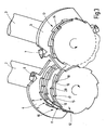
- FIG. 4 only schematically indicated mixing device 39 with Nachzerkleintationsfunktion is in FIG. 5 illustrated in more detail.
- a rotor 43 with preferably horizontally arranged axis of rotation, which is driven by a hydraulic motor or other drive source ago.
- the rotor preferably extends over the entire width of the in FIG. 4 It is at its periphery with Maschinenenbergen, eg chisels 44, 45, 46, 47 occupied, which are employed obliquely against the direction of rotation.
- pointed bits are used with a rounded tip.
- the bits 44 to 47 are rigidly mounted.
- the rotational speed of the rotor 43 is in the range of 200 to 1,000 revolutions / min for most applications. established. A speed of 400 revolutions is preferred.
- the rotor 43 is associated with a hood 48, which is arranged above the rotor 43 on the conveyor belt 34 opposite side.
- the hood preferably covers about a quarter of the circumference of the rotor 43. It is mounted on a cover 49, which is arranged above the rotor 43 about a pivot axis 50 pivotally.
- a hydraulic cylinder opens and closes the cover 49.
- the rotor is for example firmly connected to the conveyor belt 34 or to a scaffold, which also carries the rotor 43 and the conveyor belt 34.
- the hood 48 is pivotally mounted on the carrier 49 via a corresponding bearing device 51.
- the pivot axis is arranged above the rotor 43.
- the pivoting position is by an adjustment mechanism 52, for example set in the form of a simple adjusting screw or in the form of fluid cylinders (hydraulics, pneumatics).
- the hood 48 is curved approximately parallel to the circle defined by the chisels 44, 45, 46, 47 flight circle. It thus limits with the rotor 43 a gap-shaped comminuting space 53. If necessary, one, two or more blow bars 54, 55 may be held on the hood 48, which extend over the entire axial length of the rotor 43 and in the direction of the rotor 43 protrude.
- the mixing device 39 effects further mixing and comminution of the material conveyed by the conveyor belt 34.
- the grain size can be adjusted as desired with the adjustment mechanism 52. It is thus given a largely homogeneous material on the Rollenklassierer 35.
- a grinding operation is carried out in which the crushing, grinding and Störstoffbeeitungs adopted both of the relevant Excavation and in addition of lumpy coarse material is passed through.
- the crushing of the coarse material by suitable breakage and / or crushing rock powder is used as a kind of locally generated aggregate for excavation. This aggregate is suitable both to regulate the moisture of the excavation or sludge and to stabilize and solidify it.
- the material is puncture proof. Also a granulation is possible.
- the degree of drying and solidification can be adjusted by the degree of grinding, for example by the coarse constituents are ground more or less depending on the degree of moisture or desired Nachverfestist.
- coarse components such as asphalt, construction waste, concrete chunks or natural stones may be added in addition to the excavation to produce the desired amounts of rock flour during the crushing process.
- the shredder grinding and disposal facility shreds shredded contaminants and prevents the passage of non-shredded contaminants. These are rejected. For example, large steel parts are not detected or they lead to blocking and reversing of the machine. Overload or single or multiple reversing can lead to shutdown.
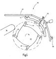
- FIGS. 6 and 7 illustrate the discs 4, 5 separately. They are preferably formed asymmetrically. As FIG. 6 illustrated, the disc 4, two diametrically opposite seats 61, 62 for chisel, as seen from FIG. 3 or for the seat 62 off FIG. 7 emerge.
- the two chisels 6, 7 define a circle 63, ie their tips run on the common diameter D2.
- the chisels 6, 7 are housed in recesses of the disk body 60, wherein the recesses in the region of the seats 61, 62 are identical. In front of the chisels 6, 7, however, distinctive recesses 64, 65 are formed.
- the recess 64 of the bit 6 extends, for example, only over a range of, for example, 60 °
- the recess 65 extends over a peripheral region of significantly more than 90 °. This allows different sized coarse components of the chisels 6, 7 are detected. While too large stones or other coarse components of the recess 64 leading hurrying area 66 of the disk body 60 are rejected, such chunks can get into the recess 65 and are detected by the chisel 7.
- the area 66 which extends up to the diameter D2 and which largely fills the space between the chisels 6, 7 prevents between the disks 4, 5 of the two shafts 2, 3 (see FIG FIG. 3 ) create too large spaces, could fall through the middle grain.
- FIGS. 6, 7 presented discs 4, 5 thus allow on the one hand the efficient crushing of particularly coarse material, while on the other hand ensure that a high proportion of fine grain is formed and the crushed material contains very little middle grain.
- the chisels 6, 7 can be the same or different as illustrated.
- the chisel 7 adjacent to the larger recess 65 may be configured for coarse shredding and the other chisel 6 for smaller size.
- liquid such as e.g. Water or an aqueous solution to which material is added.
- the addition of water can be done, for example, to effect or assist the setting of the added or generated fines.
- the removal of liquid by adding powdered dry material or moistening the material by adding water, depending on the initial moisture content of the material.
- the shredding device has a shaft with a plurality of disks, at least some of which are provided with separate shredding tools in the form of crushers. These are on the discs, for example rigidly attached.
- the breaker bits are oriented approximately in the circumferential direction and sit in corresponding recesses of the disc to which they are attached.
- the recesses have different dimensions. If one disc carries two chisels, one recess is slightly smaller while the other one is slightly larger. The larger recess allows the shredding of coarse material.
- the fact that the larger recess is associated with only one of the bits prevents gaps between adjacent shafts, in particular a twin-shaft shredder, from passing through which too much uncomminuted material can fall.
- the two-shaft shredder equipped with respective discs allows the production of small-sized material directly from coarse rock in a single crushing stage.
Abstract
Description
Die Erfindung betrifft eine Vorrichtung zur Aufbereitung von Erdaushub, Schlämmen, Müll oder sonstigem Material, das Störstoffe enthalten kann.The invention relates to a device for the treatment of excavated earth, sludges, garbage or other material that may contain contaminants.
Aus der nachveröffentlichten, jedoch prioritätsälteren
Aus dem Gebrauchsmuster
Des Weiteren ist aus der
Das so erzeugte Material eignet sich in Folge der Zerkleinerung der Grobbestandteile grundsätzlich für den Wiedereinbau, d.h. beispielsweise zum Verfüllen von ausgehobenen Bodenvertiefungen, wie Gruben oder Gräben. Allerdings ist es dazu erforderlich, dem aufzubereitenden Material einen Zuschlagstoff, wie beispielsweise Zement, Asche, Steinmehl, Granulate, Fasern, Holzspäne, Holzmehl, Suspensionen, wie beispielsweise Kalksuspensionen, Bentonite oder Dichtsuspensionen zuzugeben.The material thus produced is in principle suitable for re-installation as a result of the comminution of the coarse components. For example, for filling excavated soil pits, such as pits or trenches. However, it is necessary to add to the material to be treated an additive, such as cement, ash, stone meal, granules, fibers, wood chips, wood flour, suspensions, such as lime suspensions, bentonites or dense suspensions.
Hiervon ausgehend ist es Aufgabe, eine verbesserte Aufbereitungsvorrichtung anzugeben.On this basis, it is an object to provide an improved treatment device.
Diese Aufgabe wird mit der Vorrichtung nach Anspruch 1 gelöst:This object is achieved with the device according to claim 1:
Das aufzubereitende Material unbestimmter Form, wird z.B. in Anwesenheit von stückigem Grobmaterial einem Zerkleinerungsprozess unterworfen, bei dem das stückige Grobmaterial wenigstens teilweise zerkleinert und mit dem Material vermischt wird. Die Zerkleinerung ist dabei vorzugsweise so eingestellt, dass das stückige Grobmaterial bindungsfähige Bestandteile freisetzt. Der Prozess wird dabei so gefahren, dass die erzeugten bindungsfähigen Bestandteile, die in der Regel Feinbestandteile sind, wie ein Zuschlagstoff wirken, so dass die Aufbereitung ohne Hinzugabe von zusätzlichen Zuschlagstoffen, wie Zement, Kalk, Fasern, Spänen und dergleichen, erfolgen kann. Die zur Formstabilisierung, Trocknung und/oder Verfestigung des aufbereiteten Materials erforderlichen Feinbestandteile entstehen somit aus dem aufzubereitenden Material heraus selbst bei der Zerkleinerung des stückigen Grobmaterials. Dieses kann in dem aufzubereitenden Material in Form von Gesteinsbrocken (Kalkstein, Sandstein oder sonstiges Gestein) bereits natürlich enthalten sein. Es ist jedoch auch möglich, lehmig-tonigen Aushub, der solche Bestandteile nicht enthält, vor Durchführung des Aufbereitungsverfahrens mit entsprechendem Grobmaterial zu versetzen. Es ist weiter möglich, das Grobmaterial bei dem Zerkleinerungsvorgang hinzuzugeben. Das Grobmaterial bildet jedoch keinen Zuschlagstoff im herkömmlichen Sinne, denn es ist für sich genommen nicht bindungsfähig. Diese Eignung erhält es erst durch den Zerkleinerungs- bzw. Mahlvorgang in der Zerkleinerungseinrichtung. Diese durchläuft das stückige Grobmaterial gemeinsam mit dem Erdaushub. Es hat sich gezeigt, dass die Prozessführung dabei durchaus so eingestellt werden kann, dass trotz Anwesenheit des Erdaushubs oder eines anderen entsprechenden mineralischen Materials mit lehmig-tonigen Bestandteilen, die Erzeugung eines ausreichend großen Feinanteils aus dem Grobmaterial möglich ist. Dieser Feinanteil wird während des Zerkleinerungsvorgangs in den lehmig-tonigen Bestandteil eingemischt und wirkt dann als Zuschlagstoff. Die Bindungsfähigkeit erhält die grobstückige Komponente bei der Zerkleinerung insbesondere dann, wenn sie zumindest teilweise pulverisiert wird. Die Vermahlung des stückigen Grobmaterials kann auch separat erfolgen.The material to be processed of indefinite shape, for example, in the presence of lumpy coarse material subjected to a crushing process in which the lumpy coarse material is at least partially crushed and mixed with the material. The comminution is preferably set so that the lumpy coarse material bindable components releases. The process is driven in such a way that the bondable constituents which are generally fine constituents produced act as an aggregate, so that the treatment can take place without the addition of additional additives, such as cement, lime, fibers, chips and the like. The fine components required for stabilizing the shape, drying and / or hardening of the processed material thus arise from the material to be processed even during the comminution of the lumpy coarse material. This can already be naturally contained in the material to be treated in the form of rocks (limestone, sandstone or other rock). However, it is also possible to dislodge loamy-clay excavated material that does not contain such components before carrying out the treatment process with appropriate coarse material. It is further possible to add the coarse material in the crushing process. However, the coarse material does not form an aggregate in the traditional sense, because it is not bindable per se. This suitability is obtained only by the comminution or grinding process in the comminution device. This passes through the lumpy coarse material together with the excavation. It has been shown that the process can be set quite so that despite the presence of excavation or other appropriate mineral material with loamy clay components, the production of a sufficiently large fines from the coarse material is possible. This fine fraction is mixed during the crushing process in the loamy-clay component and then acts as an aggregate. The bondability of the lumpy component in comminution, especially when it is at least partially pulverized. The grinding of the lumpy coarse material can also be done separately.
Es ist auch möglich, dem aufzubereitenden Material vorzugsweise vor oder aber auch nach der Vermahlung einen Zuschlagstoff beizugeben, der Bindungsfähigkeit aufweist (z.B. Zement, Kalk, Stäube, Samen, Nüsse/Nussschalen). Die Zugabemenge liegt dabei aber wesentlich niedriger, als es erforderlich wäre, wenn ohne Vermahlung der Grobbestandteile gearbeitet würde. Die vermahlenen Grobbestandteile haben vor allem Wasserbindefähigkeit und erhöhen somit Stabilität und Tragfähigkeit des aufbereiteten Materials, wenn es z.B. zum Verfüllen von ausgehobenen Gräben eingesetzt wird, ohne eine unzuträgliche Nachaushärtung des Materials zu provozieren. Wird die Tragfähigkeit des aufzubereitenden Materials hingegen lediglich durch Zementzugabe herbeigeführt, härtet das Material so stark, dass ein späteres erneutes Öffnen des Grabens schwierig wird. Die Erfindung ermöglicht es, in vielen Fällen den Bedarf an zusätzlichen Zuschlagstoffen unter 0,5 Gew.% zu senken. Häufig ist zusätzlicher Zuschlagstoff ganz unnötig. Bei Wassergehalten von bis zu 30% und Steinanteil von ca. 50% kann in der Regel vollständig auf zusätzliches Bindemittel verzichtet werden.It is also possible to add to the material to be treated, preferably before or else after grinding, an aggregate having binding ability (e.g., cement, lime, dusts, seeds, nuts / nutshells). However, the amount added is much lower than would be required if work was done without grinding the coarse components. The ground coarse constituents above all have water-binding capacity and thus increase the stability and load-bearing capacity of the treated material, when e.g. is used for filling excavated ditches without provoking an unhealthy after hardening of the material. On the other hand, if the carrying capacity of the material to be treated is merely brought about by the addition of cement, the material cures so strongly that a later re-opening of the trench becomes difficult. The invention makes it possible in many cases to reduce the need for additional additives below 0.5 wt.%. Often, additional aggregate is completely unnecessary. With water contents of up to 30% and stone content of approx. 50%, it is usually possible to completely dispense with additional binder.
Ist das aufzubereitend bindiges Material, d.h. enthält er knetbare wasserhaltige Feststoffe, wie Ton oder Lehm, wirkt das beim Zerkleinerungsvorgang z.B. erzeugte Gesteinsmehl wie ein Zuschlagstoff. Das Gesteinsmehl kann je nach chemischer Beschaffenheit verschiedene Bindeeigenschaften zeigen. Beispielsweise kann es wasseraufnehmend sein. Es kann darüber hinaus durch Ionenaustauschprozesse verfestigend wirken. Es kann weiter eine puzzolanische Bindewirkung zeigen. Auch kann es durch Wasseraufnahme bindend wirken, beispielsweise wenn es Anhydridbestandteile enthält. Darüber hinaus kann es Hydratbindungen ausbilden, die durch Mikrokristallwachstum zu Stande kommen können. Dies ist insbesondere der Fall, wenn als Grobmaterial Beton oder anderweitige Bauabfälle verwendet werden. In der Regel enthalten solche Bauabfälle noch ungebundene Bestandteile und somit eine Restbindefähigkeit. Außerdem können nach dem feinen Ausmahlen Umkristallisierungsvorgänge zum erneuten Abbinden führen.If the material to be treated is cohesive, ie if it contains kneadable water-containing solids, such as clay or loam, the rock flour produced during the comminution process acts like an aggregate. The rock flour may show different binding properties depending on the chemical nature. For example, it may be water absorbent. In addition, it can have a strengthening effect through ion exchange processes. It may further show a pozzolanic binding effect. It can also act as a binding agent by absorbing water, for example when it contains anhydride components. In addition, it can form hydrate bonds that can come about through microcrystal growth. This is particularly the case when used as coarse material concrete or other construction waste be used. As a rule, such construction waste still contains unbound components and thus a residual binding capacity. In addition, recrystallization operations may result in re-setting after fine milling.
Das Material kann auch so trocken eingestellt werden, dass es siebfähig wird. Es zeigt sich, dass noch vorhandene Steine ohne wesentliche Anhaftungen von Lehm oder dergleichen ausgesiebt werden können.The material can also be adjusted to be dry enough to be sieved. It turns out that still existing stones can be screened out without significant adhesion of clay or the like.
Als besonders vorteilhaft werden Zerkleinerungseinrichtungen mit asymmetrischen Scheiben zur Aufnahme von Werkzeugen angesehen.Crushing devices with asymmetric discs for receiving tools are considered particularly advantageous.
Bei einer erfindungsgemäßen Ausführungsform der Zerkleinerungseinrichtung sind auf wenigstens einer Welle Scheiben mit Meißeln vorgesehen, wobei diese Scheiben asymmetrisch ausgebildet sind. Vor jedem Meißel ist ein Aufnahmeraum für Grobbestandteile (Steine und dergleichen) ausgebildet, wobei eine Scheibe, wenn sie zwei Meißel trägt, einen kleinen und einen großen Aufnahmeraum aufweist. Damit wird erreicht, dass einerseits sehr große, grobe Brocken zerkleinert werden können, während andererseits verhindert wird, dass größere Mengen von mittlerem Korn zwischen einander gegenüber liegenden Scheiben unzerkleinert durchfallen.In an embodiment of the shredding device according to the invention, disks with chisels are provided on at least one shaft, wherein these disks are asymmetrical. In front of each chisel, a receiving space for coarse components (stones and the like) is formed, wherein a disk, when carrying two chisels, has a small and a large receiving space. This ensures that on the one hand very large, coarse chunks can be crushed, while on the other hand prevents larger amounts of average grain between unobstructed slices fall through each other.
Weitere Einzelheiten vorteilhafter Ausführungsformen der Erfindung ergeben sich aus der Zeichnung, aus der nachfolgenden Beschreibung oder aus UnteransprüchenFurther details of advantageous embodiments of the invention will become apparent from the drawing, from the following description or from subclaims
Es zeigen:
Figur 1- die Durchführung des Verfahrens in einer schematisierten Skizze,
Figur 2- die Durchführung eines abgewandelten Verfahrens wiederum in einer schematisierten Skizze,
Figur 3- die Zerkleinerungseinrichtung nach
Figur 1 oder 2 - Figur 4
- eine abgewandelte Ausführungsform einer Einrichtung zur Durchführung des Verfahrens in schematisierter Darstellung,
- Figur 5
- eine Mischeinrichtung mit einstellbarer Nachzerkleinerung in schematisierter Seitenansicht,
Figur 6- einen Scheibenkörper der erfindungsgemäßen Zerkleinerungseinrichtung, in schematisierter Perspektivansicht, und
- Figur 7
- den
Scheibenkörper nach Figur 6 in Seitenansicht.
- FIG. 1
- the implementation of the method in a schematized sketch,
- FIG. 2
- the implementation of a modified method again in a schematized sketch,
- FIG. 3
- the crusher after
FIG. 1 or 2 in a fragmentary, perspective view, - FIG. 4
- a modified embodiment of a device for carrying out the method in a schematic representation,
- FIG. 5
- a mixing device with adjustable post-shredding in a schematic side view,
- FIG. 6
- a disk body of the shredding device according to the invention, in a schematic perspective view, and
- FIG. 7
- the disk body
FIG. 6 in side view.
In
Ansonsten sind die Wellen 2, 3 dicht mit Zahnscheiben 8 bis 14 besetzt, die untereinander gleich ausgebildet sind. Es ist auch möglich unterschiedliche Zahnscheiben zu verwenden. Die Zähne 15, 16 weisen ungefähr radial orientierte in Drehrichtung weisende Brustflächen 17, 18 und gegen die Umfangsrichtung abfallende Rückenflächen 19, 20 auf. Die Zahnscheiben 8 bis 14 sind jeweils auf Lücke angeordnet, d.h. benachbarte, auf der Welle 2 angeordnete Zahnscheiben schließen miteinander jeweils eine Lücke ein, in die die ebenfalls mit Lücken zueinander angeordneten Zahnscheiben der Welle 3 greifen. Die Anzahl der Zahnscheiben 8 bis 14 ist vorzugsweise größer als die der Meißelträgerscheiben (Scheiben 4, 5).Otherwise, the
Jeder Zahnscheibe ist auf der jeweils gegenüber liegenden Welle eine im Wesentlichen zylindrische Druckfläche zugeordnet, die mit dem Zahnrücken 18, 19 der jeweils gegenüber liegenden Zahnscheibe eine Druckspalt zum mahlenden Zerkleinern des Grobmaterials dient. Es ist jedoch auch möglich, die Zahnscheiben 8 bis 14 der beiden Wellen jeweils aneinander anliegend anzuordnen, wobei die Umfangskreise der Zahnscheiben 8 bis 14 der beiden Wellen 2, 3 einander dann nicht überschneiden. Vielmehr ist der Abstand so eingestellt, dass zwischen dem Zahnrücken der Zahnscheiben der beiden Wellen 2, 3 jeweils ein geringer Spalt verbleibt, der als Quetschspalt dient.Each toothed disc is associated with a substantially cylindrical pressure surface on the respective opposite shaft, which with the tooth back 18, 19 of the respectively opposing toothed disc serves a pressure nip for grinding the coarse material. However, it is also possible to arrange the toothed disks 8 to 14 of the two shafts adjoining each other, wherein the circumferential circles of the toothed disks 8 to 14 of the two
Die Zerkleinerungseinrichtung 1 nach
Bei Betrieb der Zerkleinerungseinrichtung 1 erfassen die von den Wellen 2, 3 getragenen Zerkleinerungswerkzeuge das lehmig-bindige Material und fördern dieses nach unten. Außerdem werden die Steine 23, 24 von den Brechmeißeln 6, 7 (
Die Zerkleinerungseinrichtung 1 nach
Bei der in
Die Dosiereinrichtung 36 ist vorzugsweise so eingestellt, dass sie lediglich geringe Stoffmengen abgibt, die weniger als 0,5 Gew.% der von den Förderbändern 33, 34 transportierten Stoffmenge ausmacht. Es kann auch eine Steuereinrichtung vorgesehen sein, die die Dosierung in Abhängigkeit von der Restfeuchte des Materials 26 festlegt. Eine entsprechende Feuchtemesseinrichtung kann vorgesehen sein, ist jedoch in
Die in
Dem Rotor 43 ist eine Haube 48 zugeordnet, die oberhalb des Rotors 43 an der dem Förderband 34 gegenüber liegenden Seite angeordnet ist. Die Haube überdeckt vorzugsweise etwa ein Viertel des Umfangs des Rotors 43. Sie ist an einer Abdeckhaube 49 gelagert, die oberhalb des Rotors 43 um eine Schwenkachse 50 schwenkbar angeordnet ist. Ein Hydraulikzylinder öffnet und schließt die Abdeckhaube 49. Der Rotor ist beispielsweise fest mit dem Förderband 34 oder mit einem Gerüst verbunden, das auch den Rotor 43 und das Förderband 34 trägt. Die Haube 48 ist über eine entsprechende Lagereinrichtung 51 an dem Träger 49 schwenkbar gelagert. Die Schwenkachse ist oberhalb des Rotors 43 angeordnet. Die Schwenkstellung wird durch einen Verstellmechanismus 52, beispielsweise in Form einer einfachen Einstellschraube oder auch in Form von Fluidzylindern (Hydraulik, Pneumatik) festgelegt.The
Die Haube 48 ist ungefähr parallel zu dem von den Meißeln 44, 45, 46, 47 festgelegten Flugkreis gekrümmt. Sie begrenzt somit mit dem Rotor 43 einen spaltförmigen Zerkleinerungsraum 53. Falls erforderlich, können an der Haube 48 ein, zwei oder mehrere Schlagleisten 54, 55 gehalten sein, die sich über die gesamte axiale Länge des Rotors 43 erstrecken und in Richtung auf den Rotor 43 vorstehen.The
In Betrieb bewirkt die Mischeinrichtung 39 eine weitere Vermischung und Zerkleinerung des von dem Förderband 34 herangefördeten Materials. Die Korngröße kann mit dem Verstellmechanismus 52 wunschgemäß eingestellt werden. Es wird somit ein weitgehend homogenes Material auf den Rollenklassierer 35 gegeben.In operation, the mixing
Zur Aufbereitung von Bodenaushub, Erdaushub oder einem anderen Material unbestimmter Form, das z.B. zum Wiedereinbau an einer Baustelle oder zur sonstigen Weiterverarbeitung oder zur Entsorgung vorgesehen werden kann, wird ein Mahlvorgang durchgeführt, bei dem die Zerkleinerungs-, Mahl- und Störstoffbeseitungseinrichtung sowohl von dem betreffenden Aushub als auch zusätzlich von stückigem Grobmaterial durchlaufen wird. Das beim Zerkleinern des Grobmaterials durch geeigneten Bruch und/oder durch Quetschvorgänge entstehende Gesteinsmehl wird als gewissermaßen vor Ort erzeugter Zuschlagstoff für den Erdaushub verwendet. Dieser Zuschlagstoff ist sowohl geeignet, die Feuchtigkeit des Erdaushubs oder Schlamms zu regulieren als auch eine Stabilisierung und Verfestigung desselben zu bewirken. Das Material wird stichfest. Auch ist eine Granulierung möglich. Das Maß der Trocknung und Verfestigung kann durch den Mahlgrad eingestellt werden, beispielsweise indem die Grobbestandteile je nach Feuchtigkeitsgrad oder gewünschter Nachverfestigung mehr oder weniger stark ausgemahlen werden. Außerdem können Grobbestandteile, wie Asphalt, Bauabfälle, Betonbrocken oder Natursteine zusätzlich zu dem Erdaushub hinzu gegeben werden, um bei dem Zerkleinerungsvorgang die gewünschten Gesteinsmehlmengen zu erzeugen. Die Zerkleinerungs-Mahl- und Störstoffbeseitigungseinrichtung zerkleinert zerkleinerbare Störstoffe und verhindert den Durchgang nicht zerkleinerbarer Störstoffe. Diese werden abgewiesen. Z.B. werden große Stahlteile nicht erfasst oder sie führen zum Blockieren und Reversieren der Maschine. Überlast oder Einoder Mehrmaliges Reversieren kann zum Abschalten führen.For the treatment of excavated soil, excavated earth or any other material of indefinite shape, which may be provided eg for re-installation at a construction site or other processing or disposal, a grinding operation is carried out in which the crushing, grinding and Störstoffbeeitungseinrichtung both of the relevant Excavation and in addition of lumpy coarse material is passed through. The crushing of the coarse material by suitable breakage and / or crushing rock powder is used as a kind of locally generated aggregate for excavation. This aggregate is suitable both to regulate the moisture of the excavation or sludge and to stabilize and solidify it. The material is puncture proof. Also a granulation is possible. The degree of drying and solidification can be adjusted by the degree of grinding, for example by the coarse constituents are ground more or less depending on the degree of moisture or desired Nachverfestigung. In addition, coarse components such as asphalt, construction waste, concrete chunks or natural stones may be added in addition to the excavation to produce the desired amounts of rock flour during the crushing process. The shredder grinding and disposal facility shreds shredded contaminants and prevents the passage of non-shredded contaminants. These are rejected. For example, large steel parts are not detected or they lead to blocking and reversing of the machine. Overload or single or multiple reversing can lead to shutdown.
Die
Bei der Materialaufbereitung kann außerdem vor oder nach dem Zerkleinern sowie wenn eine mehrstufige Zerkleinerung stattfindet zwischen den einzelnen Zerkleinerungsstufen oder in dem Zerkleinerungsprozess Flüssigkeit, wie z.B. Wasser oder eine wässrige Lösung, zu dem Material zugegeben werden. Die Wasserzugabe kann beispielsweise erfolgen, um das Abbinden des hinzugegebenen oder erzeugten Feinbestandteils zu bewirken oder zu unterstützen. Das Entziehen von Flüssigkeit durch Zugabe von pulverisierten Trockenmaterial oder das Anfeuchten des Materials durch Wasserzugabe erfolgt je nach Ausgangsfeuchtigkeit des Materials.In material processing, moreover, before or after comminution, as well as when multi-stage comminution takes place between the individual comminution stages or in the comminution process liquid such as e.g. Water or an aqueous solution to which material is added. The addition of water can be done, for example, to effect or assist the setting of the added or generated fines. The removal of liquid by adding powdered dry material or moistening the material by adding water, depending on the initial moisture content of the material.
Die erfindungsgemäße Zerkleinerungseinrichtung weist eine Welle mit mehreren Scheiben auf, von denen wenigstens einige mit gesonderten Zerkleinerungswerkzeugen in Form von Brechmeißeln versehen sind. Diese sind an den Scheiben z.B. starr befestigt. Die Brechmeißel sind ungefähr in Umfangsrichtung orientiert und sitzen in entsprechenden Ausnehmungen der Scheibe, an der sie befestigt sind. Die Ausnehmungen haben unterschiedliche Abmessungen. Trägt eine Scheibe zwei Meißel ist eine Ausnehmung etwas kleiner während die andere etwas größer ausgebildet ist. Die größere Ausnehmung gestattet die Zerkleinerung von grobem Material. Dass die größere Ausnehmung lediglich einem der Meißel zugeordnet ist verhindert andererseits, dass zwischen benachbarten Wellen, insbesondere eines Zweiwellenzerkleinerers, Lücken verbleiben, durch die zu viel unzerkleinertes Material hindurchfallen kann. Dadurch gestattet der mit entsprechenden Scheiben ausgerüstete Zweiwellenzerkleinerer die Erzeugung von kleinstückigem Material direkt aus grobem Gestein in einer einzigen Zerkleinerungsstufe.The shredding device according to the invention has a shaft with a plurality of disks, at least some of which are provided with separate shredding tools in the form of crushers. These are on the discs, for example rigidly attached. The breaker bits are oriented approximately in the circumferential direction and sit in corresponding recesses of the disc to which they are attached. The recesses have different dimensions. If one disc carries two chisels, one recess is slightly smaller while the other one is slightly larger. The larger recess allows the shredding of coarse material. On the other hand, the fact that the larger recess is associated with only one of the bits prevents gaps between adjacent shafts, in particular a twin-shaft shredder, from passing through which too much uncomminuted material can fall. Thus, the two-shaft shredder equipped with respective discs allows the production of small-sized material directly from coarse rock in a single crushing stage.
Claims (8)
- Device with a crushing device (1), which has at least one shaft carrying discs (4, 5) with crushing tools in the form of chipping chisels, wherein a respective recess is configured in front of the chipping chisels of a disc (4, 5) in the direction of rotation, wherein at least two recesses are configured differently, characterised in that the recesses (64, 65) have different lengths in the peripheral direction.
- Device according to claim 1 with a conveying device (21) for the controlled supply of the mineral material to the crushing device (1).
- Device according to claim 1 with a conveying device for the controlled supply of coarse material to the crushing device (1).
- Device according to claim 1, characterised in that a further crushing device (39) configured as a milling device is arranged downstream of the crushing device (1).
- Device according to claim 4, characterised in that the further crushing device (39) is a milling device with adjustable beating arms.
- Device according to claim 5, characterised in that the further crushing device (1) has a grinding function.
- Device according to claim 1, characterised in that the crushing device (1, 39) is a multistage crushing device.
- Device according to claim 1, characterised in that the recesses (64) have depths of different sizes.
Applications Claiming Priority (2)
| Application Number | Priority Date | Filing Date | Title |
|---|---|---|---|
| DE20314136U DE20314136U1 (en) | 2003-05-14 | 2003-09-10 | Device for processing excavated material, slurries and refuse comprises a comminuting device having a shaft supporting disks having a recess formed in the direction of rotation in front of the cutting tools of each disk |
| DE20314136U | 2003-09-10 |
Publications (3)
| Publication Number | Publication Date |
|---|---|
| EP1514603A2 EP1514603A2 (en) | 2005-03-16 |
| EP1514603A3 EP1514603A3 (en) | 2005-07-27 |
| EP1514603B1 true EP1514603B1 (en) | 2009-04-01 |
Family
ID=34129833
Family Applications (1)
| Application Number | Title | Priority Date | Filing Date |
|---|---|---|---|
| EP04021326A Not-in-force EP1514603B1 (en) | 2003-09-10 | 2004-09-08 | Device for treating material |
Country Status (3)
| Country | Link |
|---|---|
| EP (1) | EP1514603B1 (en) |
| AT (1) | ATE427161T1 (en) |
| DE (1) | DE502004009261D1 (en) |
Families Citing this family (3)
| Publication number | Priority date | Publication date | Assignee | Title |
|---|---|---|---|---|
| PL1951450T3 (en) | 2005-11-16 | 2017-10-31 | Tagpap Recycling Aps | Method and apparatus for reusing bituminous products |
| DE102016108105A1 (en) * | 2016-05-02 | 2017-11-02 | Hydro Aluminium Rolled Products Gmbh | Crushing and crushing process for crushing aluminum scrap |
| CN111632701A (en) * | 2020-05-18 | 2020-09-08 | 高梅真 | Waste treatment equipment for building engineering |
Family Cites Families (7)
| Publication number | Priority date | Publication date | Assignee | Title |
|---|---|---|---|---|
| AT393236B (en) * | 1986-07-29 | 1991-09-10 | Liezen Maschf | DEVICE FOR CRUSHING PIECE MATERIAL |
| DE4418627A1 (en) * | 1993-05-27 | 1994-12-01 | Hitachi Ltd | Process and apparatus for recovering blowing gas from foamed materials |
| US6402070B1 (en) * | 1999-02-25 | 2002-06-11 | Kyocera Corporation | Bone-mill |
| DE10235241A1 (en) * | 2002-03-14 | 2003-11-13 | Franz Gail | Corn grinding machine, for preparation of cattle feed, has hopper delivering corn past adjustable shutter to pair of motor-driven rollers and material is then delivered to motor-driven hammer mill |
| DE20214956U1 (en) * | 2002-09-27 | 2002-11-28 | Schenk Juergen | comminution device |
| DE20314136U1 (en) * | 2003-05-14 | 2003-12-04 | Schenk, Jürgen | Device for processing excavated material, slurries and refuse comprises a comminuting device having a shaft supporting disks having a recess formed in the direction of rotation in front of the cutting tools of each disk |
| WO2004101156A1 (en) * | 2003-05-14 | 2004-11-25 | Schenk Juergen | Method and device for processing excavated earth |
-
2004
- 2004-09-08 AT AT04021326T patent/ATE427161T1/en active
- 2004-09-08 EP EP04021326A patent/EP1514603B1/en not_active Not-in-force
- 2004-09-08 DE DE502004009261T patent/DE502004009261D1/en active Active
Also Published As
| Publication number | Publication date |
|---|---|
| EP1514603A2 (en) | 2005-03-16 |
| DE502004009261D1 (en) | 2009-05-14 |
| EP1514603A3 (en) | 2005-07-27 |
| ATE427161T1 (en) | 2009-04-15 |
Similar Documents
| Publication | Publication Date | Title |
|---|---|---|
| US7581689B2 (en) | Device for processing excavated material | |
| DE102005011964B4 (en) | Universal device with add-on classifier | |
| DE10202536A1 (en) | Milling device for soil, rock, excavation or other material | |
| EP1337339A1 (en) | Device and method for treating excavated material | |
| WO2004101156A1 (en) | Method and device for processing excavated earth | |
| DE3240126C2 (en) | Device for hard crushing of coarse, solidified rock mixtures | |
| EP2482987B1 (en) | Method and device for comminuting ore | |
| EP1514603B1 (en) | Device for treating material | |
| WO2016055558A1 (en) | Apparatus for comminuting ore, comprising a hydraulic spring device, and associated method | |
| EP1365901A2 (en) | Treatment method and device, in particular for excavation material | |
| DE4324234A1 (en) | Milling breaker | |
| DE19612074C2 (en) | Mobile device for improving soil material | |
| DE10111305B4 (en) | Apparatus for processing mineral materials comprises feed device having opening for feeding material, parallel rotating shafts connected with drive device, and wedge elements for producing chamfering effect | |
| DE10337590A1 (en) | Method and device for preparing excavation | |
| EP2981360B1 (en) | Apparatus and method for comminution of ore with a spring arrangement | |
| DE20314136U1 (en) | Device for processing excavated material, slurries and refuse comprises a comminuting device having a shaft supporting disks having a recess formed in the direction of rotation in front of the cutting tools of each disk | |
| EP1001093B1 (en) | Mobile apparatus for crushing stones or the like | |
| EP1267002A1 (en) | Mobile device for the screening, the separation, the breaking, the disintegration and/or the mixing | |
| JP3778689B2 (en) | Landfill waste disposal method | |
| JP2001334162A (en) | Fine granulating device for dehydrated cake | |
| DE3816872C2 (en) | ||
| EP4063030A1 (en) | Method and installation for obtaining a sand-like soil building material and its use in the production of concrete or asphalt | |
| DE2633505A1 (en) | Installation for shredding refuse - has set of rotary separating discs covered with plastic bonded abrasive particles | |
| EP1623754A1 (en) | Method and apparatus for preparation of soil materials | |
| DE102004038959A1 (en) | Excavation spoil and demolition rubble are recycled as uniform aggregates by milling between rotating breaking surfaces maintained at a speed differential to produce slippage and create surface charge on particles |
Legal Events
| Date | Code | Title | Description |
|---|---|---|---|
| PUAI | Public reference made under article 153(3) epc to a published international application that has entered the european phase |
Free format text: ORIGINAL CODE: 0009012 |
|
| AK | Designated contracting states |
Kind code of ref document: A2 Designated state(s): AT BE BG CH CY CZ DE DK EE ES FI FR GB GR HU IE IT LI LU MC NL PL PT RO SE SI SK TR |
|
| AX | Request for extension of the european patent |
Extension state: AL HR LT LV MK |
|
| PUAL | Search report despatched |
Free format text: ORIGINAL CODE: 0009013 |
|
| AK | Designated contracting states |
Kind code of ref document: A3 Designated state(s): AT BE BG CH CY CZ DE DK EE ES FI FR GB GR HU IE IT LI LU MC NL PL PT RO SE SI SK TR |
|
| AX | Request for extension of the european patent |
Extension state: AL HR LT LV MK |
|
| RIC1 | Information provided on ipc code assigned before grant |
Ipc: 7B 02C 4/30 B Ipc: 7B 02C 23/02 B Ipc: 7B 02C 18/18 B Ipc: 7B 02C 4/08 A Ipc: 7B 02C 21/00 B Ipc: 7B 02C 4/10 B Ipc: 7B 02C 18/14 B Ipc: 7B 02C 13/20 B |
|
| 17P | Request for examination filed |
Effective date: 20060111 |
|
| AKX | Designation fees paid |
Designated state(s): AT BE BG CH CY CZ DE DK EE ES FI FR GB GR HU IE IT LI LU MC NL PL PT RO SE SI SK TR |
|
| 17Q | First examination report despatched |
Effective date: 20061128 |
|
| GRAP | Despatch of communication of intention to grant a patent |
Free format text: ORIGINAL CODE: EPIDOSNIGR1 |
|
| GRAS | Grant fee paid |
Free format text: ORIGINAL CODE: EPIDOSNIGR3 |
|
| GRAA | (expected) grant |
Free format text: ORIGINAL CODE: 0009210 |
|
| AK | Designated contracting states |
Kind code of ref document: B1 Designated state(s): AT BE BG CH CY CZ DE DK EE ES FI FR GB GR HU IE IT LI LU MC NL PL PT RO SE SI SK TR |
|
| REG | Reference to a national code |
Ref country code: GB Ref legal event code: FG4D Free format text: NOT ENGLISH |
|
| REG | Reference to a national code |
Ref country code: CH Ref legal event code: EP Ref country code: CH Ref legal event code: NV Representative=s name: KIRKER & CIE S.A. |
|
| REG | Reference to a national code |
Ref country code: IE Ref legal event code: FG4D Free format text: LANGUAGE OF EP DOCUMENT: GERMAN |
|
| REF | Corresponds to: |
Ref document number: 502004009261 Country of ref document: DE Date of ref document: 20090514 Kind code of ref document: P |
|
| PG25 | Lapsed in a contracting state [announced via postgrant information from national office to epo] |
Ref country code: SI Free format text: LAPSE BECAUSE OF FAILURE TO SUBMIT A TRANSLATION OF THE DESCRIPTION OR TO PAY THE FEE WITHIN THE PRESCRIBED TIME-LIMIT Effective date: 20090401 |
|
| NLV1 | Nl: lapsed or annulled due to failure to fulfill the requirements of art. 29p and 29m of the patents act | ||
| REG | Reference to a national code |
Ref country code: IE Ref legal event code: FD4D |
|
| PG25 | Lapsed in a contracting state [announced via postgrant information from national office to epo] |
Ref country code: PT Free format text: LAPSE BECAUSE OF FAILURE TO SUBMIT A TRANSLATION OF THE DESCRIPTION OR TO PAY THE FEE WITHIN THE PRESCRIBED TIME-LIMIT Effective date: 20090902 Ref country code: FI Free format text: LAPSE BECAUSE OF FAILURE TO SUBMIT A TRANSLATION OF THE DESCRIPTION OR TO PAY THE FEE WITHIN THE PRESCRIBED TIME-LIMIT Effective date: 20090401 Ref country code: ES Free format text: LAPSE BECAUSE OF FAILURE TO SUBMIT A TRANSLATION OF THE DESCRIPTION OR TO PAY THE FEE WITHIN THE PRESCRIBED TIME-LIMIT Effective date: 20090712 Ref country code: EE Free format text: LAPSE BECAUSE OF FAILURE TO SUBMIT A TRANSLATION OF THE DESCRIPTION OR TO PAY THE FEE WITHIN THE PRESCRIBED TIME-LIMIT Effective date: 20090401 |
|
| PG25 | Lapsed in a contracting state [announced via postgrant information from national office to epo] |
Ref country code: PL Free format text: LAPSE BECAUSE OF FAILURE TO SUBMIT A TRANSLATION OF THE DESCRIPTION OR TO PAY THE FEE WITHIN THE PRESCRIBED TIME-LIMIT Effective date: 20090401 Ref country code: SE Free format text: LAPSE BECAUSE OF FAILURE TO SUBMIT A TRANSLATION OF THE DESCRIPTION OR TO PAY THE FEE WITHIN THE PRESCRIBED TIME-LIMIT Effective date: 20090701 Ref country code: NL Free format text: LAPSE BECAUSE OF FAILURE TO SUBMIT A TRANSLATION OF THE DESCRIPTION OR TO PAY THE FEE WITHIN THE PRESCRIBED TIME-LIMIT Effective date: 20090401 |
|
| PGFP | Annual fee paid to national office [announced via postgrant information from national office to epo] |
Ref country code: GB Payment date: 20090922 Year of fee payment: 6 |
|
| PG25 | Lapsed in a contracting state [announced via postgrant information from national office to epo] |
Ref country code: DK Free format text: LAPSE BECAUSE OF FAILURE TO SUBMIT A TRANSLATION OF THE DESCRIPTION OR TO PAY THE FEE WITHIN THE PRESCRIBED TIME-LIMIT Effective date: 20090401 Ref country code: CZ Free format text: LAPSE BECAUSE OF FAILURE TO SUBMIT A TRANSLATION OF THE DESCRIPTION OR TO PAY THE FEE WITHIN THE PRESCRIBED TIME-LIMIT Effective date: 20090401 Ref country code: IE Free format text: LAPSE BECAUSE OF FAILURE TO SUBMIT A TRANSLATION OF THE DESCRIPTION OR TO PAY THE FEE WITHIN THE PRESCRIBED TIME-LIMIT Effective date: 20090401 Ref country code: RO Free format text: LAPSE BECAUSE OF FAILURE TO SUBMIT A TRANSLATION OF THE DESCRIPTION OR TO PAY THE FEE WITHIN THE PRESCRIBED TIME-LIMIT Effective date: 20090401 |
|
| PLBE | No opposition filed within time limit |
Free format text: ORIGINAL CODE: 0009261 |
|
| STAA | Information on the status of an ep patent application or granted ep patent |
Free format text: STATUS: NO OPPOSITION FILED WITHIN TIME LIMIT |
|
| PG25 | Lapsed in a contracting state [announced via postgrant information from national office to epo] |
Ref country code: SK Free format text: LAPSE BECAUSE OF FAILURE TO SUBMIT A TRANSLATION OF THE DESCRIPTION OR TO PAY THE FEE WITHIN THE PRESCRIBED TIME-LIMIT Effective date: 20090401 |
|
| 26N | No opposition filed |
Effective date: 20100105 |
|
| BERE | Be: lapsed |
Owner name: SCHENK, JURGEN Effective date: 20090930 |
|
| PG25 | Lapsed in a contracting state [announced via postgrant information from national office to epo] |
Ref country code: BG Free format text: LAPSE BECAUSE OF FAILURE TO SUBMIT A TRANSLATION OF THE DESCRIPTION OR TO PAY THE FEE WITHIN THE PRESCRIBED TIME-LIMIT Effective date: 20090701 |
|
| PG25 | Lapsed in a contracting state [announced via postgrant information from national office to epo] |
Ref country code: MC Free format text: LAPSE BECAUSE OF NON-PAYMENT OF DUE FEES Effective date: 20090930 |
|
| PGFP | Annual fee paid to national office [announced via postgrant information from national office to epo] |
Ref country code: IT Payment date: 20090922 Year of fee payment: 6 |
|
| PG25 | Lapsed in a contracting state [announced via postgrant information from national office to epo] |
Ref country code: BE Free format text: LAPSE BECAUSE OF NON-PAYMENT OF DUE FEES Effective date: 20090930 |
|
| PG25 | Lapsed in a contracting state [announced via postgrant information from national office to epo] |
Ref country code: GR Free format text: LAPSE BECAUSE OF FAILURE TO SUBMIT A TRANSLATION OF THE DESCRIPTION OR TO PAY THE FEE WITHIN THE PRESCRIBED TIME-LIMIT Effective date: 20090702 |
|
| PG25 | Lapsed in a contracting state [announced via postgrant information from national office to epo] |
Ref country code: LU Free format text: LAPSE BECAUSE OF NON-PAYMENT OF DUE FEES Effective date: 20090908 |
|
| GBPC | Gb: european patent ceased through non-payment of renewal fee |
Effective date: 20100908 |
|
| PG25 | Lapsed in a contracting state [announced via postgrant information from national office to epo] |
Ref country code: IT Free format text: LAPSE BECAUSE OF NON-PAYMENT OF DUE FEES Effective date: 20100908 |
|
| REG | Reference to a national code |
Ref country code: FR Ref legal event code: ST Effective date: 20110531 |
|
| PG25 | Lapsed in a contracting state [announced via postgrant information from national office to epo] |
Ref country code: HU Free format text: LAPSE BECAUSE OF FAILURE TO SUBMIT A TRANSLATION OF THE DESCRIPTION OR TO PAY THE FEE WITHIN THE PRESCRIBED TIME-LIMIT Effective date: 20091002 |
|
| PG25 | Lapsed in a contracting state [announced via postgrant information from national office to epo] |
Ref country code: FR Free format text: LAPSE BECAUSE OF NON-PAYMENT OF DUE FEES Effective date: 20100930 |
|
| PG25 | Lapsed in a contracting state [announced via postgrant information from national office to epo] |
Ref country code: TR Free format text: LAPSE BECAUSE OF FAILURE TO SUBMIT A TRANSLATION OF THE DESCRIPTION OR TO PAY THE FEE WITHIN THE PRESCRIBED TIME-LIMIT Effective date: 20090401 Ref country code: GB Free format text: LAPSE BECAUSE OF NON-PAYMENT OF DUE FEES Effective date: 20100908 |
|
| PG25 | Lapsed in a contracting state [announced via postgrant information from national office to epo] |
Ref country code: CY Free format text: LAPSE BECAUSE OF FAILURE TO SUBMIT A TRANSLATION OF THE DESCRIPTION OR TO PAY THE FEE WITHIN THE PRESCRIBED TIME-LIMIT Effective date: 20090401 |
|
| PGFP | Annual fee paid to national office [announced via postgrant information from national office to epo] |
Ref country code: FR Payment date: 20091001 Year of fee payment: 6 |
|
| PGFP | Annual fee paid to national office [announced via postgrant information from national office to epo] |
Ref country code: CH Payment date: 20110923 Year of fee payment: 8 |
|
| PGFP | Annual fee paid to national office [announced via postgrant information from national office to epo] |
Ref country code: AT Payment date: 20110914 Year of fee payment: 8 |
|
| PGFP | Annual fee paid to national office [announced via postgrant information from national office to epo] |
Ref country code: DE Payment date: 20120930 Year of fee payment: 9 |
|
| REG | Reference to a national code |
Ref country code: CH Ref legal event code: PL |
|
| REG | Reference to a national code |
Ref country code: AT Ref legal event code: MM01 Ref document number: 427161 Country of ref document: AT Kind code of ref document: T Effective date: 20120908 |
|
| PG25 | Lapsed in a contracting state [announced via postgrant information from national office to epo] |
Ref country code: CH Free format text: LAPSE BECAUSE OF NON-PAYMENT OF DUE FEES Effective date: 20120930 Ref country code: AT Free format text: LAPSE BECAUSE OF NON-PAYMENT OF DUE FEES Effective date: 20120908 Ref country code: LI Free format text: LAPSE BECAUSE OF NON-PAYMENT OF DUE FEES Effective date: 20120930 |
|
| REG | Reference to a national code |
Ref country code: DE Ref legal event code: R119 Ref document number: 502004009261 Country of ref document: DE Effective date: 20140401 |
|
| PG25 | Lapsed in a contracting state [announced via postgrant information from national office to epo] |
Ref country code: DE Free format text: LAPSE BECAUSE OF NON-PAYMENT OF DUE FEES Effective date: 20140401 |