EP1513698B1 - Pare-soleil pour interieur d'automobile - Google Patents
Pare-soleil pour interieur d'automobile Download PDFInfo
- Publication number
- EP1513698B1 EP1513698B1 EP03732472A EP03732472A EP1513698B1 EP 1513698 B1 EP1513698 B1 EP 1513698B1 EP 03732472 A EP03732472 A EP 03732472A EP 03732472 A EP03732472 A EP 03732472A EP 1513698 B1 EP1513698 B1 EP 1513698B1
- Authority
- EP
- European Patent Office
- Prior art keywords
- sun visor
- visor body
- glare
- arm
- essentially
- Prior art date
- Legal status (The legal status is an assumption and is not a legal conclusion. Google has not performed a legal analysis and makes no representation as to the accuracy of the status listed.)
- Expired - Lifetime
Links
Images



Classifications
-
- B—PERFORMING OPERATIONS; TRANSPORTING
- B60—VEHICLES IN GENERAL
- B60J—WINDOWS, WINDSCREENS, NON-FIXED ROOFS, DOORS, OR SIMILAR DEVICES FOR VEHICLES; REMOVABLE EXTERNAL PROTECTIVE COVERINGS SPECIALLY ADAPTED FOR VEHICLES
- B60J3/00—Antiglare equipment associated with windows or windscreens; Sun visors for vehicles
- B60J3/02—Antiglare equipment associated with windows or windscreens; Sun visors for vehicles adjustable in position
- B60J3/0204—Sun visors
- B60J3/0213—Sun visors characterised by the mounting means
Definitions
- the invention relates to a folding from a non-use position in anti-glare positions sun visor for the interior of a motor vehicle, which has a sun visor and a guide device, wherein the sun visor body from a first, substantially frontal anti-glare position in a second, substantially lateral anti-glare position is pivotally, wherein the sun visor body is guided by means of the guide device in such a way that in each glare protection position, the same surface side of the sun visor body facing the vehicle interior.
- the publication DE 29 02 734 A1 describes a sun visor, which is fastened by means of a ball joint via a flexible, ie flexible holder or a chain of links on the vehicle ceiling. This ensures that the sun visor can be placed freely in front of the driver in the room and can be rotated transversely and highly adjustable in all directions. A defined guidance of the sun visor is deliberately avoided by this arrangement.
- sun visor consists of a sun visor body which is hinged by means of a rotatably mounted in a bearing block on the one hand and in the sun visor body, L-shaped bearing bracket both from a horizontal non-use position down and from a glare protection position in front of the windshield in front of the side window of the vehicle.
- the surface side of the sun visor body pointing outwards in the first, frontal anti-glare position faces the vehicle interior in the second, side glare protection position.
- This general training is disadvantageous in that on a surface side of the visor body attached equipment, such as mirrors, holding devices for parking tickets or the like, only in one, usually the frontal anti-glare position for the occupants are accessible.
- the invention has for its object to provide a sun visor, which avoids the disadvantages of the prior art.
- the sun visor body is guided by means of a guide device in such a way that the sun visor body on the one hand via an arrangement provided on the headliner of the vehicle rail guide and on the other is guided by a both the arrangement provided on the headliner and the sun visor body rotatably arranged articulated arm of the first to the second anti-glare position pivotally.
- the articulated arm advantageously comprises two cranked half-arms, which are rotatable relative to one another about a substantially horizontal axis when the sun visor is being folded from the non-use position into an anti-glare position.
- the half-arms may have two rotatable plug-in legs to produce a joint.
- the first half-arm for pivoting the sun visor from the first to the second anti-glare position about a first substantially vertical axis in the headliner and the second half-arm are rotatably mounted about a first axis parallel offset second vertical axis in the sun visor body.
- the articulated arm can be releasably latched by means of a detent mechanism to the sun visor body located in the first, frontal anti-glare position.
- the rail guide advantageously has a roof rail mounted, substantially transversely to the direction of travel horizontally arranged guide rail and attached to the sun visor body slider.
- the slider may be provided with a cranked arm piece that is rotatable about a substantially vertical axis relative to the guide rail upon pivoting of the sun visor from the first to the second anti-glare position.
- the sun visor body is hinged about a substantially horizontal leg of the arm piece from the non-use to a glare protection position.
- the arm piece and the articulated arm are in operative connection in such a way that the sun visor body can only be folded from the non-use position to an antiglare position when the horizontal legs of the articulated arm on the one hand and the horizontal leg of the arm piece on the other hand are aligned with each other.
- the sun visor body By acting in the region of the horizontal leg of the arm piece locking device, the sun visor body can be kept releasably, in particular in its usually about horizontal non-use position.
- the object is further achieved according to a further embodiment of the invention in that in a sun visor according to the preamble of claim 11, the sun visor body is guided by means of a guide means in such a way that the sun visor body via a four-joint forming pair of articulated arms with substantially vertical axes of rotation relative to the headliner is pivotally guided from the first to the second anti-glare position.
- the pair of articulated arms can be mounted on the sun visor body side in a joint block, in which the sun visor in turn is hinged for pivoting from the non-use to an antiglare position about a substantially horizontal articulation axis, preferably using a locking device acting in the region of the horizontal axis, in particular the sun visor body keeps detachable in the non-use position.
- the articulated arms of the four-bar link advantageously in the first and / or second anti-glare position to form an end stop, wherein between the articulated arms in the region of the end stop acting latching device can be provided which holds the sun visor body in the desired glare protection position.
- at least one joint of the four-bar linkage for locking the sun visor body in the first and / or second anti-glare position can be executed by overcoming a dead center overstretched like a toggle.
- sun visor 1 consists of a sun visor body 2, which is connected via a guide device 3 with the headliner 4 of a motor vehicle.
- the guide means 3 includes, as well as off Fig. 2 seen, on the one hand a rail guide 5 with a stationary on the headliner 4 arranged guide rail 5a, which extends horizontally and transversely to the direction of travel (Y-axis of the vehicle).
- a slider 6 is inserted longitudinally displaceable, which in turn is a cranked arm piece. 7 receives.
- the arm piece 7 is rotatable with its first leg 8 about a vertical axis 9 in the slider 6 and with its second leg 10 about a horizontal axis 11 in the sun visor body 2.
- the guide device 3 further consists of an articulated arm 12, which is composed of two cranked half-arms 13, 14.
- the first half-arm 13 is mounted with a leg 15 rotatable about a vertical axis of rotation 16 in a headliner 4 mounted near the side window of the vehicle Lagerböckchen 17, while the second half-arm 14 with a leg 18 about a vertical axis of rotation 19 rotatable approximately centrally in the upper edge of the sun visor body 2 engages.
- Both half-arms 13, 14 are further connected to each other with their other, plug-in legs 20, 21 about a horizontal axis of rotation 22 rotatably connected to each other.
- the sun visor body 2 has at its upper edge a recess 23, which creates the necessary space for receiving the articulated arm 12 space.
- the sun visor body from an approximately horizontal non-use position, in which it may be applied to the headliner 4, down in front of the windshield in the front glare protection position (position A) can be folded ,
- the half arms 13, 14 rotate relative to each other about the horizontal axis of rotation 22 and the arm piece 7 about the horizontal axis of rotation 11 relative to the sun visor body second
- the sun visor body from this position via any intermediate positions (for example, position C) in a side anti-glare position (position B) is pivotally in which the side window of the vehicle is partially covered.
- the articulated arm 12 rotates in Lagerböckchen 17 and sun visor body 2 about the vertical axes of rotation 16 and 19.
- the slider 6 is horizontal and transverse to Direction of travel in the guide rail 5a outwardly shifted towards the side window, with the arm piece 7 in the slider 6 is rotated about the vertical axis of rotation 9. The pivoting back into the frontal anti-glare position is done with reversed movement.
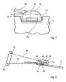
- FIG. 3 An unintentional pivoting of the sun visor body in the lateral glare protection position can by the in Fig. 3 shown enlarged latching device 24 can be avoided.
- a horizontally protruding from the half-bar 13 outward projection 25 is latched in the lateral region of the recess 23 of the sun visor body 2.
- the detent connections can be released and the sun visor body 2 can be pivoted into the lateral glare protection position without reaching around.
- a locking device 27 is provided with a force acting on a flattening 28 of the leg 10 of the arm piece 7 leaf spring 29, through which the sun visor body 2 is releasably held in the non-use position.
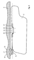
- the guide device 3 for the sun visor body 2 is designed as a four-bar linkage, with a double-cranked pair of articulated arms 30, 31 being rotatably mounted at one end in the bearing block 17 and at the other end in a joint block 32 about vertical axes of rotation 33 to 36 , While the Lagerböckchen 17 is fixedly connected to the headliner 4, the joint block 32 additionally takes a recessed into the sun visor body 2 axle piece 37 to this can be folded from any non-use position in a glare protection position.
- An analogous to the device described above locking device 27 in the joint block 32 holds the sun visor body 2 while in the non-use position ( Fig. 7 ).
- the sun visor body 2 In the frontal anti-glare position (position A), the sun visor body 2 is held in that the four-bar link beyond a dead center 38 in the toggle manner in the in Fig. 8 shown position is overstretched, with the articulated arms 30, 31 deform elastically in the short term.
- a virtual straight line X connecting the axes of rotation 35, 36 in the joint block 32 is no longer aligned with the rear axis of rotation 34 in the end position, but instead forms an obtuse angle ⁇ with the associated articulated arm 31.
- the cranked, the axis of rotation 36 forming region of the rear articulated arm 31 is applied to the side of the other articulated arm 30 and thus serves as an end stop for the four-bar linkage.
- a releasable latching device 39 acting between the articulated arms 30, 31.
- the sun visor body 2 can be kept in the side anti-glare position.
Landscapes
- Engineering & Computer Science (AREA)
- Mechanical Engineering (AREA)
- Arrangements Of Lighting Devices For Vehicle Interiors, Mounting And Supporting Thereof, Circuits Therefore (AREA)
- Vehicle Step Arrangements And Article Storage (AREA)
- Vehicle Interior And Exterior Ornaments, Soundproofing, And Insulation (AREA)
- Pivots And Pivotal Connections (AREA)
- Helmets And Other Head Coverings (AREA)
- Tents Or Canopies (AREA)
Claims (16)
- Pare-soleil (1) pouvant être rabattu d'une position de non utilisation dans des positions anti-éblouissement pour l'habitacle d'un véhicule automobile, qui présente un corps de pare-soleil (2) et un dispositif de guidage (3), le corps de pare-soleil (2) pouvant pivoter d'une première position anti-éblouissement essentiellement frontale (position A) dans une deuxième position anti-éblouissement essentiellement latérale (position B), et le corps de pare-soleil (2) étant guidé au moyen du dispositif de guidage (3) de telle sorte que, dans chaque position anti-éblouissement, le même côté de surface du corps de pare-soleil soit tourné vers l'habitacle du véhicule, caractérisé en ce que le corps de pare-soleil (2) est guidé de manière pivotante de la première dans la deuxième position anti-éblouissement, d'une part par le biais d'une glissière sur rail (5) prévue pour être disposée sur l'habillage du toit (4) du véhicule, et d'autre part par le biais d'un bras articulé (12) prévu pour être disposé sur l'habillage du toit et également disposé de manière rotative sur le corps de pare-soleil.
- Pare-soleil selon la revendication 1, caractérisé en ce que le bras articulé (12) comprend deux demi-bras coudés (13), (14) qui, lors du rabattement du pare-soleil (1) de la position de non utilisation dans la position anti-éblouissement frontale peuvent tourner l'un par rapport à l'autre autour d'un axe de rotation (22) essentiellement horizontal.
- Pare-soleil selon la revendication 2, caractérisé en ce que les demi-bras (13), (14) présentent deux branches (20), (21) pouvant être enfoncées l'une dans l'autre par rotation.
- Pare-soleil selon la revendication 2 ou 3, caractérisé en ce que le premier demi-bras (20) est monté de manière rotative autour d'un axe de rotation (16) essentiellement vertical dans l'habillage du toit pour faire pivoter le corps de pare-soleil (2) de la première dans la deuxième position anti-éblouissement, et le deuxième demi-bras (21) est monté de manière rotative autour d'un axe de rotation (19) décalé parallèlement à l'axe de rotation (16) dans le corps de pare-soleil.
- Pare-soleil selon l'une quelconque des revendications 1 à 4, caractérisé en ce que le bras articulé (12) peut être encliqueté au moyen d'un dispositif d'encliquetage (24) de manière détachable avec le corps de pare-soleil (2) se trouvant dans la première position anti-éblouissement frontale.
- Pare-soleil selon l'une quelconque des revendications 1 à 5, caractérisé en ce que la glissière sur rail (5) présente un rail de guidage (5a) fixé à l'habillage du toit, disposé essentiellement horizontalement transversalement à la direction de conduite, et un coulisseau (6) fixé sur le corps de pare-soleil (2).
- Pare-soleil selon la revendication 6, caractérisé en ce que le coulisseau (6) est pourvu d'un élément de bras coudé (7), qui, lors du pivotement du corps de pare-soleil (2) de la première dans la deuxième position anti-éblouissement, peut tourner par rapport au rail de guidage (5a) autour d'un axe de rotation essentiellement vertical (9).
- Pare-soleil selon la revendication 7, caractérisé en ce que le corps de pare-soleil (2) peut être rabattu de la position de non utilisation dans la position anti-éblouissement frontale autour d'une branche (10) essentiellement horizontale de l'élément de bras (7).
- Pare-soleil selon la revendication 8, caractérisé en ce que l'élément de bras (7) et le bras articulé (12) sont en liaison fonctionnelle de telle sorte que le corps de pare-soleil (2) ne puisse être rabattu de la position de non utilisation dans une position anti-éblouissement que lorsque les branches horizontales (15), (18) du bras articulé (12) d'une part et la branche horizontale (10) de l'élément de bras (7) d'autre part sont alignées mutuellement.
- Pare-soleil selon l'une quelconque des revendications 1 à 9, caractérisé par un dispositif de blocage (27) agissant dans la région de la branche horizontale (10) de l'élément de bras (7), retenant de manière détachable le corps de pare-soleil (2), notamment dans la position de non utilisation.
- Pare-soleil (1) pouvant être rabattu d'une position de non utilisation dans des positions anti-éblouissement pour l'habitacle d'un véhicule automobile, qui présente un corps de pare-soleil (2) et un dispositif de guidage (3), le corps de pare-soleil (2) pouvant pivoter d'une première position anti-éblouissement essentiellement frontale (position A) dans une deuxième position anti-éblouissement essentiellement latérale (position B), et le corps de pare-soleil (2) étant guidé au moyen du dispositif de guidage (3) de telle sorte que dans chaque position anti-éblouissement, le même côté de surface du corps de pare-soleil soit tourné vers l'habitacle du véhicule, caractérisé en ce que le corps de pare-soleil (2) est guidé de manière pivotante de la première dans la deuxième position anti-éblouissement par le biais d'une paire de bras articulés (30), (31) formant un quadrilatère articulé, avec des axes de rotation essentiellement verticaux (33), (34), (35), (36), par rapport à l'habillage du toit (4).
- Pare-soleil selon la revendication 11, caractérisé en ce que la paire de bras articulés (30), (31) est montée à rotation du côté du corps de pare-soleil dans un bloc articulé (32), dans lequel le corps de pare-soleil (2) est disposé pour sa part de manière à pouvoir être rabattu de la position de non utilisation dans une position anti-éblouissement autour d'un élément d'axe essentiellement horizontal (37).
- Pare-soleil selon la revendication 12, caractérisé par un dispositif de blocage (27) agissant dans la région de l'élément d'axe horizontal (37), qui retient de manière détachable le corps de pare-soleil (2) notamment dans la position de non utilisation.
- Pare-soleil selon l'une quelconque des revendications 11 à 13, caractérisé en ce que les bras articulés (30), (31) sont en contact dans la première et/ou dans la deuxième position anti-éblouissement pour former une butée de fin de course.
- Pare-soleil selon la revendication 14, caractérisé par un dispositif d'encliquetage (39) agissant entre les bras articulés (30), (31) dans la région de la butée de fin de course.
- Pare-soleil selon l'une quelconque des revendications 11 à 15, caractérisé en ce qu'au moins une articulation du quadrilatère articulé peut être étirée en forme de genouillère pour bloquer le corps de pare-soleil (2) dans la première et/ou la deuxième position anti-éblouissement en surmontant un point mort (38).
Applications Claiming Priority (3)
| Application Number | Priority Date | Filing Date | Title |
|---|---|---|---|
| DE10224835 | 2002-06-05 | ||
| DE10224835A DE10224835B4 (de) | 2002-06-05 | 2002-06-05 | Sonnenblende für den Innenraum eines Kraftfahrzeugs |
| PCT/EP2003/005523 WO2003104003A1 (fr) | 2002-06-05 | 2003-05-27 | Pare-soleil pour interieur d'automobile |
Publications (2)
| Publication Number | Publication Date |
|---|---|
| EP1513698A1 EP1513698A1 (fr) | 2005-03-16 |
| EP1513698B1 true EP1513698B1 (fr) | 2008-08-20 |
Family
ID=29718836
Family Applications (1)
| Application Number | Title | Priority Date | Filing Date |
|---|---|---|---|
| EP03732472A Expired - Lifetime EP1513698B1 (fr) | 2002-06-05 | 2003-05-27 | Pare-soleil pour interieur d'automobile |
Country Status (7)
| Country | Link |
|---|---|
| US (1) | US7111890B2 (fr) |
| EP (1) | EP1513698B1 (fr) |
| JP (1) | JP4302626B2 (fr) |
| AT (1) | ATE405440T1 (fr) |
| DE (2) | DE10224835B4 (fr) |
| ES (1) | ES2316767T3 (fr) |
| WO (1) | WO2003104003A1 (fr) |
Families Citing this family (10)
| Publication number | Priority date | Publication date | Assignee | Title |
|---|---|---|---|---|
| WO2006099212A2 (fr) | 2005-03-11 | 2006-09-21 | Tadakamalla, Anand | Pare-soleil retractable et protege- pare-brise integral |
| DE102005012860B4 (de) * | 2005-03-17 | 2008-10-30 | Johnson Controls Interiors Gmbh & Co. Kg | Befestigungsvorrichtung für ein Fahrzeug zur Befestigung einer Komponente, insbesondere einer Sonnenblende |
| US7537263B2 (en) | 2006-10-17 | 2009-05-26 | Delphia John B | Visor assembly for a vehicle |
| US8038199B2 (en) * | 2008-05-21 | 2011-10-18 | Marcus Automotive, Llc | Visor |
| US8925995B2 (en) | 2011-10-03 | 2015-01-06 | Marcus Automotive, Llc | Rotatable side window visor and glare shield |
| US8714621B2 (en) * | 2011-12-21 | 2014-05-06 | Marcus Automotive, Llc | Visor with movable pivot |
| JP7106428B2 (ja) | 2018-10-26 | 2022-07-26 | 共和産業株式会社 | 車両用サンバイザ |
| KR102952658B1 (ko) * | 2020-02-26 | 2026-04-16 | 현대자동차주식회사 | 슬림구조를 가지는 슬라이딩 선바이저 |
| WO2021224932A1 (fr) * | 2020-05-04 | 2021-11-11 | Mku Limited | Système de montage de visière sur des casques balistiques |
| CN116373562B (zh) * | 2023-04-11 | 2026-04-07 | 北京海纳川汽车部件股份有限公司 | 车辆的遮阳板装置及车辆 |
Family Cites Families (51)
| Publication number | Priority date | Publication date | Assignee | Title |
|---|---|---|---|---|
| US390790A (en) * | 1888-10-09 | Sunshade for vehicles | ||
| US1664124A (en) * | 1926-05-10 | 1928-03-27 | John M Lorenz | Glare shield |
| US1806059A (en) * | 1928-05-14 | 1931-05-19 | Charles I Hoople | Adjustable antiglare shield |
| US1913277A (en) * | 1931-05-16 | 1933-06-06 | Hoople Charles Isaac | Antiglare shield |
| US1941032A (en) * | 1932-10-26 | 1933-12-26 | George P Knowles | Glare shield |
| US2695193A (en) * | 1950-10-09 | 1954-11-23 | Richard T Hamel | Dual purpose sun visor |
| DE2902734A1 (de) * | 1979-01-25 | 1980-08-07 | Wilhelm Dr Ing Lepper | Blendschutzklappen-halterung in kraftfahrzeugen |
| US4762359A (en) | 1984-11-02 | 1988-08-09 | Prince Corporation | Visor system |
| US4681363A (en) | 1985-11-07 | 1987-07-21 | Prince Corporation | Visor system |
| US4783111A (en) | 1986-05-23 | 1988-11-08 | Prince Corporation | Visor |
| US5071186A (en) | 1986-05-23 | 1991-12-10 | Prince Corporation | Visor |
| US5080420A (en) | 1986-05-23 | 1992-01-14 | Prince Corporation | Visor |
| US4925232A (en) | 1986-05-23 | 1990-05-15 | Prince Corporation | Visor |
| DE3710429A1 (de) * | 1987-03-28 | 1988-10-13 | Bayerische Motoren Werke Ag | Sonnenblende fuer kraftfahrzeuge |
| DE3829976C1 (fr) * | 1988-09-03 | 1990-03-08 | Gebr. Happich Gmbh, 5600 Wuppertal, De | |
| US5067765A (en) | 1989-07-24 | 1991-11-26 | Prince Corporation | Flexible sun visor with over-center spring |
| US4989910A (en) | 1990-01-31 | 1991-02-05 | Prince Corporation | Pivoted slide-out visor panel |
| US5219199A (en) | 1990-10-26 | 1993-06-15 | Prince Corporation | Stabilized slide-out visor |
| DE4129689A1 (de) | 1991-09-09 | 1993-03-11 | Happich Gmbh Gebr | Sonnenschutzblende |
| US5182675A (en) | 1991-12-12 | 1993-01-26 | Prince Corporation | Pivot down articulated mirror |
| US5205604A (en) | 1991-12-20 | 1993-04-27 | Prince Corporation | Low profile visor assembly |
| US5186442A (en) | 1992-01-28 | 1993-02-16 | Prince Corporation | Visor with double acting slide mechanism |
| US5211439A (en) | 1992-03-31 | 1993-05-18 | Prince Corporation | Curvilinear sliding visor |
| US5186512A (en) | 1992-04-16 | 1993-02-16 | Prince Corporation | Rear window sliding visor |
| JPH05330339A (ja) * | 1992-05-29 | 1993-12-14 | Tadayasu Hiraoka | 窓取付け型日除け具 |
| DE4234741A1 (de) | 1992-10-15 | 1994-04-21 | Happich Gmbh Gebr | Sonnenblende für Fahrzeuge |
| US5374097A (en) | 1993-04-15 | 1994-12-20 | Prince Corporation | Universal visor mounting system |
| DE4326102A1 (de) | 1993-08-04 | 1995-02-09 | Happich Gmbh Gebr | Spiegel mit Beleuchtungseinrichtung, insbesondere für Fahrzeuge |
| US5328227A (en) | 1993-09-27 | 1994-07-12 | Prince Corporation | Extendable pivoted visor panel |
| DE4337808A1 (de) | 1993-11-05 | 1995-05-11 | Happich Gmbh Gebr | Sonnenblende für Fahrzeuge |
| US5428513A (en) | 1993-11-17 | 1995-06-27 | Prince Corporation | Covered vanity mirror and flexible circuit |
| US5529367A (en) | 1994-01-12 | 1996-06-25 | Prince Corporation | Visor with sliding pivot mount |
| US5429513A (en) * | 1994-02-10 | 1995-07-04 | Diaz-Plaza; Ruth R. | Interactive teaching apparatus and method for teaching graphemes, grapheme names, phonemes, and phonetics |
| DE19523067A1 (de) | 1994-08-02 | 1996-02-08 | Happich Gmbh Gebr | Sonnenblende für Fahrzeuge |
| DE19504248A1 (de) | 1995-02-09 | 1996-08-22 | Happich Gmbh Gebr | Sonnenblende für Fahrzeuge |
| US5577792A (en) | 1995-02-21 | 1996-11-26 | Prince Corporation | Multiple visor system with aligned pivot axes |
| US5538310A (en) | 1995-04-24 | 1996-07-23 | Prince Corporation | Track visor |
| US5871251A (en) | 1996-03-14 | 1999-02-16 | Prince Corporation | Visor display |
| US5810421A (en) | 1996-09-16 | 1998-09-22 | Prince Corporation | Multiple function visor |
| DE19731535C2 (de) | 1997-07-23 | 2003-03-27 | Johnson Contr Interiors Gmbh | Sonnenblende für Fahrzeuge |
| US5851046A (en) * | 1997-08-29 | 1998-12-22 | Prince Corporation | Track visor |
| DE19749795C2 (de) | 1997-11-11 | 2002-11-14 | Johnson Contr Interiors Gmbh | Sonnenblende für Kraftfahrzeuge |
| US5975708A (en) | 1997-11-25 | 1999-11-02 | Prince Corporation | Visor with pivoting vanity mirror assembly |
| US6203161B1 (en) | 1997-11-25 | 2001-03-20 | Prince Corporation | Visor with pivoting vanity mirror assembly |
| DE19857454A1 (de) | 1998-12-12 | 2000-08-10 | Johnson Contr Interiors Gmbh | Sonnenblende für Fahrzeuge |
| DE10020106C1 (de) | 2000-04-22 | 2001-05-17 | Johnson Contr Interiors Gmbh | Sonnenblende für Fahrzeuge |
| US6328370B1 (en) * | 2000-08-29 | 2001-12-11 | Sang R. Kim | Horizontally and vertically positionable sun visor |
| US6409246B1 (en) | 2001-08-13 | 2002-06-25 | Johnson Controls Technology Company | Snap-in hinged visor extender |
| JP4261165B2 (ja) | 2002-11-25 | 2009-04-30 | 河西工業株式会社 | 自動車のサンバイザ装置 |
| US7017304B2 (en) | 2002-11-27 | 2006-03-28 | Automotive Components Holdings, Llc | Panel assembly for a motor vehicle |
| AU2003297394A1 (en) | 2002-12-20 | 2004-07-22 | Donnelly Corporation | Accessory system for vehicle |
-
2002
- 2002-06-05 DE DE10224835A patent/DE10224835B4/de not_active Expired - Fee Related
-
2003
- 2003-05-27 WO PCT/EP2003/005523 patent/WO2003104003A1/fr not_active Ceased
- 2003-05-27 JP JP2004511098A patent/JP4302626B2/ja not_active Expired - Fee Related
- 2003-05-27 AT AT03732472T patent/ATE405440T1/de not_active IP Right Cessation
- 2003-05-27 EP EP03732472A patent/EP1513698B1/fr not_active Expired - Lifetime
- 2003-05-27 DE DE50310368T patent/DE50310368D1/de not_active Expired - Lifetime
- 2003-05-27 US US10/516,396 patent/US7111890B2/en not_active Expired - Fee Related
- 2003-05-27 ES ES03732472T patent/ES2316767T3/es not_active Expired - Lifetime
Also Published As
| Publication number | Publication date |
|---|---|
| ATE405440T1 (de) | 2008-09-15 |
| US7111890B2 (en) | 2006-09-26 |
| EP1513698A1 (fr) | 2005-03-16 |
| JP2005528284A (ja) | 2005-09-22 |
| WO2003104003A1 (fr) | 2003-12-18 |
| DE50310368D1 (de) | 2008-10-02 |
| US20050206186A1 (en) | 2005-09-22 |
| DE10224835B4 (de) | 2005-04-07 |
| DE10224835A1 (de) | 2004-01-08 |
| JP4302626B2 (ja) | 2009-07-29 |
| ES2316767T3 (es) | 2009-04-16 |
Similar Documents
| Publication | Publication Date | Title |
|---|---|---|
| EP1065085B1 (fr) | Vehicule équipé avec un toit rigide | |
| EP1080966A2 (fr) | Capote pour cabriolet | |
| DE19939954B4 (de) | Faltschiebedachanordnung | |
| DE10224835B4 (de) | Sonnenblende für den Innenraum eines Kraftfahrzeugs | |
| EP2170640A1 (fr) | Pare-soleil | |
| DE102005025262B4 (de) | Sonnenschutzblende für ein Kraftfahrzeug | |
| DE102011104492B3 (de) | Vorrichtung mit einer Sonnenblende für ein Cabriofahrzeug | |
| EP0928711A2 (fr) | Articulation pour couvercle de coffre de capote | |
| DE102005012860B4 (de) | Befestigungsvorrichtung für ein Fahrzeug zur Befestigung einer Komponente, insbesondere einer Sonnenblende | |
| EP2539166A1 (fr) | Dispositif de protection contre les rayons du soleil pour voiture particulière | |
| EP4101764B1 (fr) | Dispositif formant une table pour un véhicule | |
| DE102005045213B4 (de) | Faltverdeck eines Kraftfahrzeugs | |
| DE10103554A1 (de) | Blendschutzeinrichtung für ein Fahrzeg, insbesondere für ein Kraftfahrzeug | |
| DE102018211256B4 (de) | Türantrieb für eine Kraftwagentür sowie Halteanordnung | |
| DE3525149C1 (de) | Sonnenblenden für ein Kraftfahrzeug die in den Übergangsbereichen zwischen dem Dach und den Seitenwänden angeordnet sind | |
| DE9307481U1 (de) | Klappverdeck für Kraftfahrzeuge | |
| DE112020003418B4 (de) | Sonnenblende für ein fahrzeug | |
| DE10237612B3 (de) | Kraftfahrzeugsitz | |
| DE10301796A1 (de) | Sonnenblende für ein Kraftfahrzeug | |
| DE10131541A1 (de) | Kraftfahrzeug mit einer verschwenkbaren Dacheinheit | |
| DE102017009115A1 (de) | Flügeltür für ein Fahrzeug | |
| DE10205227A1 (de) | Schwenkverdeck für ein Kraftfahrzeug | |
| DE3910811A1 (de) | Sonnenblende fuer kraftfahrzeuge | |
| DE10118432A1 (de) | Make-up Spiegel | |
| DE2902734A1 (de) | Blendschutzklappen-halterung in kraftfahrzeugen |
Legal Events
| Date | Code | Title | Description |
|---|---|---|---|
| PUAI | Public reference made under article 153(3) epc to a published international application that has entered the european phase |
Free format text: ORIGINAL CODE: 0009012 |
|
| 17P | Request for examination filed |
Effective date: 20050105 |
|
| AK | Designated contracting states |
Kind code of ref document: A1 Designated state(s): AT BE BG CH CY CZ DE DK EE ES FI FR GB GR HU IE IT LI LU MC NL PT RO SE SI SK TR |
|
| GRAP | Despatch of communication of intention to grant a patent |
Free format text: ORIGINAL CODE: EPIDOSNIGR1 |
|
| GRAS | Grant fee paid |
Free format text: ORIGINAL CODE: EPIDOSNIGR3 |
|
| GRAA | (expected) grant |
Free format text: ORIGINAL CODE: 0009210 |
|
| AK | Designated contracting states |
Kind code of ref document: B1 Designated state(s): AT BE BG CH CY CZ DE DK EE ES FI FR GB GR HU IE IT LI LU MC NL PT RO SE SI SK TR |
|
| REG | Reference to a national code |
Ref country code: GB Ref legal event code: FG4D Free format text: NOT ENGLISH |
|
| REG | Reference to a national code |
Ref country code: CH Ref legal event code: EP |
|
| REG | Reference to a national code |
Ref country code: IE Ref legal event code: FG4D Free format text: LANGUAGE OF EP DOCUMENT: GERMAN |
|
| REF | Corresponds to: |
Ref document number: 50310368 Country of ref document: DE Date of ref document: 20081002 Kind code of ref document: P |
|
| REG | Reference to a national code |
Ref country code: SE Ref legal event code: TRGR |
|
| PG25 | Lapsed in a contracting state [announced via postgrant information from national office to epo] |
Ref country code: NL Free format text: LAPSE BECAUSE OF FAILURE TO SUBMIT A TRANSLATION OF THE DESCRIPTION OR TO PAY THE FEE WITHIN THE PRESCRIBED TIME-LIMIT Effective date: 20080820 |
|
| PG25 | Lapsed in a contracting state [announced via postgrant information from national office to epo] |
Ref country code: FI Free format text: LAPSE BECAUSE OF FAILURE TO SUBMIT A TRANSLATION OF THE DESCRIPTION OR TO PAY THE FEE WITHIN THE PRESCRIBED TIME-LIMIT Effective date: 20080820 Ref country code: SI Free format text: LAPSE BECAUSE OF FAILURE TO SUBMIT A TRANSLATION OF THE DESCRIPTION OR TO PAY THE FEE WITHIN THE PRESCRIBED TIME-LIMIT Effective date: 20080820 |
|
| REG | Reference to a national code |
Ref country code: IE Ref legal event code: FD4D |
|
| REG | Reference to a national code |
Ref country code: ES Ref legal event code: FG2A Ref document number: 2316767 Country of ref document: ES Kind code of ref document: T3 |
|
| PG25 | Lapsed in a contracting state [announced via postgrant information from national office to epo] |
Ref country code: IE Free format text: LAPSE BECAUSE OF FAILURE TO SUBMIT A TRANSLATION OF THE DESCRIPTION OR TO PAY THE FEE WITHIN THE PRESCRIBED TIME-LIMIT Effective date: 20080820 Ref country code: DK Free format text: LAPSE BECAUSE OF FAILURE TO SUBMIT A TRANSLATION OF THE DESCRIPTION OR TO PAY THE FEE WITHIN THE PRESCRIBED TIME-LIMIT Effective date: 20080820 Ref country code: BG Free format text: LAPSE BECAUSE OF FAILURE TO SUBMIT A TRANSLATION OF THE DESCRIPTION OR TO PAY THE FEE WITHIN THE PRESCRIBED TIME-LIMIT Effective date: 20081120 |
|
| PG25 | Lapsed in a contracting state [announced via postgrant information from national office to epo] |
Ref country code: SK Free format text: LAPSE BECAUSE OF FAILURE TO SUBMIT A TRANSLATION OF THE DESCRIPTION OR TO PAY THE FEE WITHIN THE PRESCRIBED TIME-LIMIT Effective date: 20080820 Ref country code: CZ Free format text: LAPSE BECAUSE OF FAILURE TO SUBMIT A TRANSLATION OF THE DESCRIPTION OR TO PAY THE FEE WITHIN THE PRESCRIBED TIME-LIMIT Effective date: 20080820 Ref country code: RO Free format text: LAPSE BECAUSE OF FAILURE TO SUBMIT A TRANSLATION OF THE DESCRIPTION OR TO PAY THE FEE WITHIN THE PRESCRIBED TIME-LIMIT Effective date: 20080820 Ref country code: PT Free format text: LAPSE BECAUSE OF FAILURE TO SUBMIT A TRANSLATION OF THE DESCRIPTION OR TO PAY THE FEE WITHIN THE PRESCRIBED TIME-LIMIT Effective date: 20090120 |
|
| PLBE | No opposition filed within time limit |
Free format text: ORIGINAL CODE: 0009261 |
|
| STAA | Information on the status of an ep patent application or granted ep patent |
Free format text: STATUS: NO OPPOSITION FILED WITHIN TIME LIMIT |
|
| 26N | No opposition filed |
Effective date: 20090525 |
|
| PG25 | Lapsed in a contracting state [announced via postgrant information from national office to epo] |
Ref country code: EE Free format text: LAPSE BECAUSE OF FAILURE TO SUBMIT A TRANSLATION OF THE DESCRIPTION OR TO PAY THE FEE WITHIN THE PRESCRIBED TIME-LIMIT Effective date: 20080820 |
|
| BERE | Be: lapsed |
Owner name: JOHNSON CONTROLS INTERIORS G.M.B.H. Effective date: 20090531 |
|
| PG25 | Lapsed in a contracting state [announced via postgrant information from national office to epo] |
Ref country code: MC Free format text: LAPSE BECAUSE OF NON-PAYMENT OF DUE FEES Effective date: 20090531 |
|
| REG | Reference to a national code |
Ref country code: CH Ref legal event code: PL |
|
| PG25 | Lapsed in a contracting state [announced via postgrant information from national office to epo] |
Ref country code: LI Free format text: LAPSE BECAUSE OF NON-PAYMENT OF DUE FEES Effective date: 20090531 Ref country code: CH Free format text: LAPSE BECAUSE OF NON-PAYMENT OF DUE FEES Effective date: 20090531 |
|
| PG25 | Lapsed in a contracting state [announced via postgrant information from national office to epo] |
Ref country code: BE Free format text: LAPSE BECAUSE OF NON-PAYMENT OF DUE FEES Effective date: 20090531 |
|
| PG25 | Lapsed in a contracting state [announced via postgrant information from national office to epo] |
Ref country code: AT Free format text: LAPSE BECAUSE OF NON-PAYMENT OF DUE FEES Effective date: 20090527 |
|
| PG25 | Lapsed in a contracting state [announced via postgrant information from national office to epo] |
Ref country code: GR Free format text: LAPSE BECAUSE OF FAILURE TO SUBMIT A TRANSLATION OF THE DESCRIPTION OR TO PAY THE FEE WITHIN THE PRESCRIBED TIME-LIMIT Effective date: 20081121 |
|
| PG25 | Lapsed in a contracting state [announced via postgrant information from national office to epo] |
Ref country code: LU Free format text: LAPSE BECAUSE OF NON-PAYMENT OF DUE FEES Effective date: 20090527 |
|
| PG25 | Lapsed in a contracting state [announced via postgrant information from national office to epo] |
Ref country code: HU Free format text: LAPSE BECAUSE OF FAILURE TO SUBMIT A TRANSLATION OF THE DESCRIPTION OR TO PAY THE FEE WITHIN THE PRESCRIBED TIME-LIMIT Effective date: 20090221 |
|
| PG25 | Lapsed in a contracting state [announced via postgrant information from national office to epo] |
Ref country code: TR Free format text: LAPSE BECAUSE OF FAILURE TO SUBMIT A TRANSLATION OF THE DESCRIPTION OR TO PAY THE FEE WITHIN THE PRESCRIBED TIME-LIMIT Effective date: 20080820 |
|
| PG25 | Lapsed in a contracting state [announced via postgrant information from national office to epo] |
Ref country code: CY Free format text: LAPSE BECAUSE OF FAILURE TO SUBMIT A TRANSLATION OF THE DESCRIPTION OR TO PAY THE FEE WITHIN THE PRESCRIBED TIME-LIMIT Effective date: 20080820 |
|
| PGFP | Annual fee paid to national office [announced via postgrant information from national office to epo] |
Ref country code: GB Payment date: 20140521 Year of fee payment: 12 |
|
| PGFP | Annual fee paid to national office [announced via postgrant information from national office to epo] |
Ref country code: IT Payment date: 20140528 Year of fee payment: 12 Ref country code: SE Payment date: 20140520 Year of fee payment: 12 |
|
| REG | Reference to a national code |
Ref country code: FR Ref legal event code: PLFP Year of fee payment: 13 |
|
| GBPC | Gb: european patent ceased through non-payment of renewal fee |
Effective date: 20150527 |
|
| PG25 | Lapsed in a contracting state [announced via postgrant information from national office to epo] |
Ref country code: IT Free format text: LAPSE BECAUSE OF NON-PAYMENT OF DUE FEES Effective date: 20150527 |
|
| PG25 | Lapsed in a contracting state [announced via postgrant information from national office to epo] |
Ref country code: SE Free format text: LAPSE BECAUSE OF NON-PAYMENT OF DUE FEES Effective date: 20150528 |
|
| PG25 | Lapsed in a contracting state [announced via postgrant information from national office to epo] |
Ref country code: GB Free format text: LAPSE BECAUSE OF NON-PAYMENT OF DUE FEES Effective date: 20150527 |
|
| REG | Reference to a national code |
Ref country code: FR Ref legal event code: PLFP Year of fee payment: 14 |
|
| PGFP | Annual fee paid to national office [announced via postgrant information from national office to epo] |
Ref country code: ES Payment date: 20160715 Year of fee payment: 14 |
|
| REG | Reference to a national code |
Ref country code: FR Ref legal event code: PLFP Year of fee payment: 15 |
|
| REG | Reference to a national code |
Ref country code: FR Ref legal event code: PLFP Year of fee payment: 16 |
|
| REG | Reference to a national code |
Ref country code: ES Ref legal event code: FD2A Effective date: 20180706 |
|
| PG25 | Lapsed in a contracting state [announced via postgrant information from national office to epo] |
Ref country code: ES Free format text: LAPSE BECAUSE OF NON-PAYMENT OF DUE FEES Effective date: 20170528 |
|
| PGFP | Annual fee paid to national office [announced via postgrant information from national office to epo] |
Ref country code: DE Payment date: 20190521 Year of fee payment: 17 |
|
| PGFP | Annual fee paid to national office [announced via postgrant information from national office to epo] |
Ref country code: FR Payment date: 20190522 Year of fee payment: 17 |
|
| REG | Reference to a national code |
Ref country code: DE Ref legal event code: R119 Ref document number: 50310368 Country of ref document: DE |
|
| PG25 | Lapsed in a contracting state [announced via postgrant information from national office to epo] |
Ref country code: FR Free format text: LAPSE BECAUSE OF NON-PAYMENT OF DUE FEES Effective date: 20200531 |
|
| PG25 | Lapsed in a contracting state [announced via postgrant information from national office to epo] |
Ref country code: DE Free format text: LAPSE BECAUSE OF NON-PAYMENT OF DUE FEES Effective date: 20201201 |