EP1513377A1 - Fluoreszenzlampe des elektrodenlosen glühbirnentyps und entladungslampenbeleuchtungs einrichtung - Google Patents
Fluoreszenzlampe des elektrodenlosen glühbirnentyps und entladungslampenbeleuchtungs einrichtung Download PDFInfo
- Publication number
- EP1513377A1 EP1513377A1 EP03730856A EP03730856A EP1513377A1 EP 1513377 A1 EP1513377 A1 EP 1513377A1 EP 03730856 A EP03730856 A EP 03730856A EP 03730856 A EP03730856 A EP 03730856A EP 1513377 A1 EP1513377 A1 EP 1513377A1
- Authority
- EP
- European Patent Office
- Prior art keywords
- voltage
- fluorescent lamp
- lamp
- dimming
- electrodeless
- Prior art date
- Legal status (The legal status is an assumption and is not a legal conclusion. Google has not performed a legal analysis and makes no representation as to the accuracy of the status listed.)
- Withdrawn
Links
Images


Classifications
-
- H—ELECTRICITY
- H05—ELECTRIC TECHNIQUES NOT OTHERWISE PROVIDED FOR
- H05B—ELECTRIC HEATING; ELECTRIC LIGHT SOURCES NOT OTHERWISE PROVIDED FOR; CIRCUIT ARRANGEMENTS FOR ELECTRIC LIGHT SOURCES, IN GENERAL
- H05B41/00—Circuit arrangements or apparatus for igniting or operating discharge lamps
- H05B41/14—Circuit arrangements
- H05B41/36—Controlling
- H05B41/38—Controlling the intensity of light
- H05B41/39—Controlling the intensity of light continuously
- H05B41/392—Controlling the intensity of light continuously using semiconductor devices, e.g. thyristor
- H05B41/3921—Controlling the intensity of light continuously using semiconductor devices, e.g. thyristor with possibility of light intensity variations
-
- H—ELECTRICITY
- H05—ELECTRIC TECHNIQUES NOT OTHERWISE PROVIDED FOR
- H05B—ELECTRIC HEATING; ELECTRIC LIGHT SOURCES NOT OTHERWISE PROVIDED FOR; CIRCUIT ARRANGEMENTS FOR ELECTRIC LIGHT SOURCES, IN GENERAL
- H05B41/00—Circuit arrangements or apparatus for igniting or operating discharge lamps
- H05B41/14—Circuit arrangements
- H05B41/26—Circuit arrangements in which the lamp is fed by power derived from dc by means of a converter, e.g. by high-voltage dc
- H05B41/28—Circuit arrangements in which the lamp is fed by power derived from dc by means of a converter, e.g. by high-voltage dc using static converters
- H05B41/2806—Circuit arrangements in which the lamp is fed by power derived from dc by means of a converter, e.g. by high-voltage dc using static converters with semiconductor devices and specially adapted for lamps without electrodes in the vessel, e.g. surface discharge lamps, electrodeless discharge lamps
- H05B41/2813—Arrangements for protecting lamps or circuits against abnormal operating conditions
-
- H—ELECTRICITY
- H05—ELECTRIC TECHNIQUES NOT OTHERWISE PROVIDED FOR
- H05B—ELECTRIC HEATING; ELECTRIC LIGHT SOURCES NOT OTHERWISE PROVIDED FOR; CIRCUIT ARRANGEMENTS FOR ELECTRIC LIGHT SOURCES, IN GENERAL
- H05B41/00—Circuit arrangements or apparatus for igniting or operating discharge lamps
- H05B41/14—Circuit arrangements
- H05B41/26—Circuit arrangements in which the lamp is fed by power derived from dc by means of a converter, e.g. by high-voltage dc
- H05B41/28—Circuit arrangements in which the lamp is fed by power derived from dc by means of a converter, e.g. by high-voltage dc using static converters
- H05B41/282—Circuit arrangements in which the lamp is fed by power derived from dc by means of a converter, e.g. by high-voltage dc using static converters with semiconductor devices
- H05B41/285—Arrangements for protecting lamps or circuits against abnormal operating conditions
- H05B41/2851—Arrangements for protecting lamps or circuits against abnormal operating conditions for protecting the circuit against abnormal operating conditions
- H05B41/2853—Arrangements for protecting lamps or circuits against abnormal operating conditions for protecting the circuit against abnormal operating conditions against abnormal power supply conditions
-
- H—ELECTRICITY
- H05—ELECTRIC TECHNIQUES NOT OTHERWISE PROVIDED FOR
- H05B—ELECTRIC HEATING; ELECTRIC LIGHT SOURCES NOT OTHERWISE PROVIDED FOR; CIRCUIT ARRANGEMENTS FOR ELECTRIC LIGHT SOURCES, IN GENERAL
- H05B41/00—Circuit arrangements or apparatus for igniting or operating discharge lamps
- H05B41/14—Circuit arrangements
- H05B41/36—Controlling
- H05B41/38—Controlling the intensity of light
- H05B41/39—Controlling the intensity of light continuously
- H05B41/392—Controlling the intensity of light continuously using semiconductor devices, e.g. thyristor
- H05B41/3921—Controlling the intensity of light continuously using semiconductor devices, e.g. thyristor with possibility of light intensity variations
- H05B41/3924—Controlling the intensity of light continuously using semiconductor devices, e.g. thyristor with possibility of light intensity variations by phase control, e.g. using a triac
-
- H—ELECTRICITY
- H05—ELECTRIC TECHNIQUES NOT OTHERWISE PROVIDED FOR
- H05B—ELECTRIC HEATING; ELECTRIC LIGHT SOURCES NOT OTHERWISE PROVIDED FOR; CIRCUIT ARRANGEMENTS FOR ELECTRIC LIGHT SOURCES, IN GENERAL
- H05B41/00—Circuit arrangements or apparatus for igniting or operating discharge lamps
- H05B41/14—Circuit arrangements
- H05B41/36—Controlling
- H05B41/38—Controlling the intensity of light
- H05B41/39—Controlling the intensity of light continuously
- H05B41/392—Controlling the intensity of light continuously using semiconductor devices, e.g. thyristor
- H05B41/3921—Controlling the intensity of light continuously using semiconductor devices, e.g. thyristor with possibility of light intensity variations
- H05B41/3927—Controlling the intensity of light continuously using semiconductor devices, e.g. thyristor with possibility of light intensity variations by pulse width modulation
-
- Y—GENERAL TAGGING OF NEW TECHNOLOGICAL DEVELOPMENTS; GENERAL TAGGING OF CROSS-SECTIONAL TECHNOLOGIES SPANNING OVER SEVERAL SECTIONS OF THE IPC; TECHNICAL SUBJECTS COVERED BY FORMER USPC CROSS-REFERENCE ART COLLECTIONS [XRACs] AND DIGESTS
- Y02—TECHNOLOGIES OR APPLICATIONS FOR MITIGATION OR ADAPTATION AGAINST CLIMATE CHANGE
- Y02B—CLIMATE CHANGE MITIGATION TECHNOLOGIES RELATED TO BUILDINGS, e.g. HOUSING, HOUSE APPLIANCES OR RELATED END-USER APPLICATIONS
- Y02B20/00—Energy efficient lighting technologies, e.g. halogen lamps or gas discharge lamps
-
- Y—GENERAL TAGGING OF NEW TECHNOLOGICAL DEVELOPMENTS; GENERAL TAGGING OF CROSS-SECTIONAL TECHNOLOGIES SPANNING OVER SEVERAL SECTIONS OF THE IPC; TECHNICAL SUBJECTS COVERED BY FORMER USPC CROSS-REFERENCE ART COLLECTIONS [XRACs] AND DIGESTS
- Y10—TECHNICAL SUBJECTS COVERED BY FORMER USPC
- Y10S—TECHNICAL SUBJECTS COVERED BY FORMER USPC CROSS-REFERENCE ART COLLECTIONS [XRACs] AND DIGESTS
- Y10S315/00—Electric lamp and discharge devices: systems
- Y10S315/04—Dimming circuit for fluorescent lamps
Definitions
- the present invention relates to discharge lamp operating devices.
- the present invention relates to electrodeless self-ballasted fluorescent lamps in which electrodeless fluorescent lamps can be dimmed.
- a fluorescent lamp has been widely used from global environmental protection and economic standpoints because it has a higher degree of efficiency and a longer life as compared with an incandescent lamp.
- an electrodeless self-ballasted fluorescent lamp having no electrode has been attracting much attention since its life is several times longer than that of a conventional self-ballasted fluorescent lamp having electrodes, and the demand for an electrodeless self-ballasted fluorescent lamp is on the increase.
- a self-ballasted fluorescent lamp in which a fluorescent lamp and a ballast circuit therefor are integrally formed is becoming a focus of attention as an energy-saving light source in houses, hotels, restaurants or the like, and is now becoming widespread because the self-ballasted fluorescent lamp can be readily used as it is in place of an incandescent lamp.
- the self-ballasted fluorescent lamp of this type having electrodes the self-ballasted fluorescent lamp of this type having no electrode is also under development.
- a self-ballasted fluorescent lamp having electrodes requires preheating of the electrodes for the discharge of electrons therefrom, and thus needs a voltage of a certain level. Therefore, if deeper dimming is carried out using a fluorescent lamp having electrodes, extinguishing occurs at the instant when a dimming voltage becomes lower than a voltage required for preheating of the electrodes, thus making it impossible to carry out smooth dimming.
- the present applicant has already developed an electrodeless self-ballasted fluorescent lamp that is dimmable, and succeeded in completing such a lamp; however, this lamp still has inadequacies. For example, undesired extinguishing or flickering of the lamp occurs when low level dimming is carried out, and therefore, smooth dimming operation might not be achieved.
- the present invention has been made in view of the above-described problems, and its main object is to provide an electrodeless self-ballasted fluorescent lamp and a discharge lamp operating device which achieve smooth dimming operation.
- An inventive electrodeless self-ballasted fluorescent lamp includes: an electrodeless fluorescent lamp; a ballast circuit for applying a high-frequency voltage to the electrodeless fluorescent lamp; and a lamp base electrically connected to the ballast circuit, wherein the electrodeless fluorescent lamp, the ballast circuit and the lamp base are formed as one unit, wherein the ballast circuit includes: an AC-DC converter for converting a phase-controlled AC voltage into a DC voltage; a DC-AC converter for converting the DC voltage into a high-frequency voltage, the DC-AC converter being formed so as to intermittently drive the electrodeless fluorescent lamp due to the existence of an operating period during which the high-frequency voltage is applied to the electrodeless fluorescent lamp so that the electrodeless fluorescent lamp is operated, and an extinguishing period during which the generation of the high-frequency voltage is stopped so that the electrodeless fluorescent lamp is extinguished; and a dimming controller for detecting the turn-on of the phase-controlled AC voltage and for outputting an intermittent command signal that changes the ratio between the operating period and the extinguishing period to the
- the dimming controller includes: a first dimming control signal input section and a second dimming control signal input section; a sawtooth wave generator for generating a sawtooth wave; and a dimming command signal generator for generating a dimming command signal, the first dimming control signal input section is connected to the sawtooth wave generator via a photo coupler, and the second dimming control signal input section is connected to the dimming command signal generator.
- the sawtooth wave generator and the dimming command signal generator are connected to a comparator.
- the dimming controller is further formed so as to output a signal for synchronizing the timing of the turn-on with that of the operation of the lamp intermittently driven by the DC-AC converter.
- the dimming controller has a sawtooth wave generator including a differentiating circuit that includes a capacitor and a resistor, the differentiating circuit is connected to a collector terminal of a transistor for generating a pulse wave synchronized with the turn-on and turn-off of the phase-controlled AC voltage, an output terminal of the differentiating circuit is connected with an anode of a diode while a cathode of the diode is connected with a base terminal of a transistor for discharge, an emitter terminal of the transistor for discharge is connected with a diode for potential adjustment, and a capacitor for charge and discharge is connected between the emitter terminal and collector terminal of the transistor for discharge, thus allowing the generation of a sawtooth wave synchronized with the turn-on of the phase-controlled voltage.
- a sawtooth wave generator including a differentiating circuit that includes a capacitor and a resistor, the differentiating circuit is connected to a collector terminal of a transistor for generating a pulse wave synchronized with the turn-on and turn
- the phase-controlled AC voltage is an output voltage of a dimmer which has been phase-controlled by the dimmer.
- An inventive discharge lamp operating device includes: a discharge lamp; an AC-DC converter for converting a phase-controlled AC voltage into a DC voltage; a DC-AC converter for converting the DC voltage into a high-frequency voltage, the DC-AC converter intermittently driving the discharge lamp due to the existence of an operating period during which the high-frequency voltage is applied to the discharge lamp so that the discharge lamp is operated, and an extinguishing period during which the generation of the high-frequency voltage is stopped so that the discharge lamp is extinguished; and a dimming controller for detecting the turn-on of the phase-controlled AC voltage and for outputting an intermittent command signal that changes the ratio between the operating period and the extinguishing period to the DC-AC converter, wherein the discharge lamp is an electrodeless discharge lamp, and wherein the dimming controller is formed so as to output a signal for extinguishing the discharge lamp before the operation thereof becomes unstable.
- the dimming controller is further formed so as to output a signal for synchronizing the timing of the turn-on with that of the operation of the lamp intermittently driven by the DC-AC converter.
- the discharge lamp has a discharge bulb with a recessed portion, and an induction coil is inserted into the recessed portion of the discharge bulb.
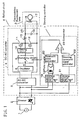
- FIG. 1 schematically shows the configuration of a discharge lamp operating device according to a first embodiment of the present invention.
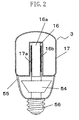
- FIG. 2 is a cross-sectional view of the discharge lamp operating device of the present embodiment implemented as an electrodeless self-ballasted fluorescent lamp.
- the electrodeless self-ballasted fluorescent lamp of the present embodiment includes: an electrodeless fluorescent lamp 3; a ballast circuit 4 (circuit board 54) for applying a high-frequency voltage to the electrodeless fluorescent lamp 3; and a lamp base 56 electrically connected to the ballast circuit 4 (circuit board 54).
- the circuit board 54 shown in FIG. 2 is formed with the ballast circuit 4 shown in FIG. 1.
- the circuit board 54 is formed with wirings provided as shown in the ballast circuit 4, and is attached with respective circuit components.
- the electrodeless fluorescent lamp 3 includes a discharge bulb 17 having a recessed portion 17a, and an induction coil 16 made up of a core 16a and a coil 16b is inserted into the recessed portion 17a.
- the coil 16b is electrically connected to the circuit board 54, and a cover 55 for accommodating the circuit board 54 is provided around the circuit board 54.
- the lamp base 56 e.g., E26 type for incandescent lamp
- An AC voltage inputted through the lamp base 56 is an AC voltage that is phase-controlled by, for example, an external phase controller (such as a dimmer 2 shown in FIG. 1 , typically a dimmer for an incandescent lamp).
- an external phase controller such as a dimmer 2 shown in FIG. 1 , typically a dimmer for an incandescent lamp.
- the ballast circuit 4 shown in FIG. 1 includes: an AC-DC converter 5 for converting a phase-controlled AC voltage into a DC voltage; a DC-AC converter 6 for converting the DC voltage, which has been converted in the AC-DC converter 5, into a high-frequency voltage; and a dimming controller 7.
- the AC-DC converter 5, the DC-AC converter 6 and the dimming controller 7 may be called a converter for smoothing an AC voltage into a DC voltage, an inverter and a detector (detection means), respectively.
- the ballast circuit 4 is connected to a commercial power supply 1 via the dimmer 2 for carrying out the phase control of a voltage supplied from the commercial power supply 1. Furthermore, the ballast circuit 4 operates the electrodeless fluorescent lamp 3 in response to the turn-on of the voltage phase-controlled in the dimmer 2.
- the commercial power supply 1 is an AC power supply for 60Hz and 100V, for example, and the dimmer 2 is connected thereto.
- the dimmer 2 is one that carries out phase control using a triac, and a commercially available dimmer for an incandescent lamp can be typically used as the dimmer 2.
- the AC-DC converter 5 converts the phase-controlled voltage, supplied from the dimmer 2, into a DC voltage.
- the AC-DC converter 5 one that utilizes a diode bridge and a smoothing capacitor, for example, may be used.
- the DC-AC converter 6 is formed so as to intermittently drive the electrodeless fluorescent lamp 3 due to the existence of an operating period during which the converted high-frequency voltage is applied to the electrodeless fluorescent lamp 3 so that the electrodeless fluorescent lamp 3 is operated, and an extinguishing period during which the generation of the high-frequency voltage is stopped so that the electrodeless fluorescent lamp 3 is extinguished.
- the DC-AC converter 6 of the present embodiment includes: an oscillator 8; a switching circuit 9; a driving circuit 10; switching elements (MOSFETs 11 and 12); a resonant inductor 13; and resonant capacitors 14 and 15.
- the induction coil 16 is connected to the resonant capacitor 15 in series, and furthermore, a series circuit of the induction coil 16 and the resonant capacitor 15 is connected to the resonant capacitor 14 in parallel.
- the electrodeless fluorescent lamp 3 is formed by the induction coil 16 and the electrodeless discharge bulb 17.
- the induction coil 16 is made up of the ferrite core 16a and the coil 16b, and is placed into the recessed portion 17a of the discharge bulb 17.
- the dimming controller 7 is formed so as to detect the turn-on of the phase-controlled AC voltage, and so as to output an intermittent command signal for changing the ratio between the operating period and extinguishing period to the DC-AC converter 6 (in particular, the switching circuit 9). Further, the dimming controller 7 is formed so as to output a signal for extinguishing the electrodeless fluorescent lamp 3 before the operation thereof becomes unstable. Furthermore, the dimming controller 7 of the present embodiment is formed so as to output a signal for synchronizing the timing of the turn-on with that of the operation of the electrodeless fluorescent lamp 3 intermittently driven by the DC-AC converter 6. In other words, the dimming controller 7 can be called a synchronous type duty modulator.
- the dimming controller 7 of the present embodiment includes: a dimming control signal input section A 18; a photo coupler 19; a sawtooth wave generator 20; a dimming command signal input section B 21; a dimming command signal generator 22; and a comparator 23 (e.g., a comparator formed using an operational amplifier).
- a dimming control signal input section A 18 and the sawtooth wave generator 20 can be insulated from each other; therefore, noise reduction can be achieved, and performance increase can be attained.
- a sawtooth wave is generated using the dimming control signal input section A 18, to which the voltage phase-controlled by the dimmer 2 is inputted, the photo coupler 19 and the sawtooth wave generator 20.
- a dimming command signal is generated using the dimming command signal input section B 21 and the dimming command signal generator 22, and then, the sawtooth wave is sent to the non-inverting input terminal of the comparator 23 while the dimming command signal is sent to the inverting input terminal of the comparator 23; thus, from the resulting voltage difference, the comparator 23 generates an intermittent dimming signal.
- an output voltage from the commercial power supply 1 is phase-controlled in the dimmer 2, and then the phase-controlled AC voltage is converted into a DC voltage in the AC-DC converter 5.
- the driving circuit 10 for the MOSFETs 11 and 12 of the DC-AC converter 6 is driven in response to an output at a driving frequency f1 (Hz) from the oscillator 8.
- a driving frequency f1 Hz
- the high-frequency voltage is applied to a resonant circuit made up of the resonant inductor 13, the resonant capacitors 14 and 15, and the induction coil 16. Due to a current flowing through the induction coil 16, an AC electromagnetic field is generated within the electrodeless discharge bulb 17, and an energy supplied by the AC electromagnetic filed causes excitation of a light-emitting gas (not shown) enclosed within the electrodeless discharge bulb, resulting in light emission.
- a light-emitting gas for example, mercury, krypton, xenon or a gas mixture thereof may be used.
- a gas containing only a rare gas but no mercury may also be used.
- the timing of the turn-on of the phase-controlled voltage is detected by the dimming controller 7, and the turn-on of the intermittent command signal synchronized with the turn-on of the phase-controlled voltage occurs in the dimming controller 7 and is transmitted to the switching circuit 9.
- the switching circuit 9 is turned on, and the driving circuit 10 for the MOSFETs 11 and 12 is turned on.
- the switching circuit 9 is turned off, and the driving circuit 10 for the MOSFETs 11 and 12 is turned off.
- the driving frequency f1 (Hz) the driving frequency
- the ratio between the on period and off period of the switching circuit 9, determined by the intermittent command signal from the dimming controller 7, is changed, and in accordance with this change, the ratio between the on period and off period of the MOSFETs 11 and 12 (which will be herein called a duty ratio) is varied. That is, the variation in the duty ratio causes a change in an electric energy input to the electrodeless fluorescent lamp 3, thus carrying out dimming of the electrodeless fluorescent lamp 3.
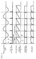
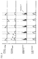
- FIG. 3 shows the relationships among a phase-controlled voltage a, a turn-on detection signal b, a sawtooth wave c, a dimming command signal d, an intermittent command signal e, and a light output f, wherein in the five charts, each horizontal axis is a time axis, and the time axis serves as a common measure in the respective charts.
- the phase-controlled voltage a in FIG. 3 is first inputted to the dimming control signal input section A 18 in the dimming controller 7 shown in FIG. 1. Then, the phase-controlled voltage a is full-wave rectified in the dimming control signal input section A 18, and is subsequently reduced to a voltage (e.g., 2V) appropriate for the driving of the photo coupler 19 and applied to the photo coupler 19.
- a voltage e.g., 2V
- a pulse wave synchronized with the turn-on and turn-off of the phase-controlled voltage a is outputted from a transistor that forms a part of the photo coupler 19. Then, due to the existence of an IC such as a monostable multivibrator, the sawtooth wave generator 20 outputs the turn-on detection signal b synchronized only with the turn-on of the phase-controlled voltage a by using, as a trigger input, the turn-on signal from the photo coupler 19.
- the turn-on detection signal b is sent to a base terminal of the transistor, a capacitor connected between an emitter and a collector of the transistor is charged and discharged, and the sawtooth wave c is outputted.
- the phase-controlled voltage a is inputted to the dimming control signal input section B 21 of the dimming controller 7 shown in FIG. 1, and is half-wave rectified by the dimming control signal input section B 21. Then, in the dimming command signal generator 22, the half-wave rectified portion of the phase-controlled voltage is integrated, and thereafter the dimming command signal d is outputted.
- the comparator 23 receives, at its non-inverting input terminal and inverting input terminal, the sawtooth wave c and the dimming command signal d, respectively, and outputs the intermittent command signal e in accordance with the potential difference between both the signals.
- the intermittent command signal e is transmitted to the switching circuit 9, and during the on period of the intermittent command signal e, the MOSFETs 11 and 12 of the DC-AC converter 6 are driven with the driving frequency f1 (Hz), thereby obtaining the light output f.
- the on state of the intermittent command signal e is maintained until the potential of the sawtooth wave c becomes higher than that of the dimming command signal d. Upon inversion of the potential relationship, the intermittent command signal e becomes off, which is transmitted to the switching circuit 9, and the driving of the MOSFETs 11 and 12 is stopped, thus extinguishing light.
- the duty of the intermittent command signal e is determined by the potential relationship between the potential of the sawtooth wave c and that of the dimming command signal d, and furthermore, the operation during the on period of the intermittent command signal and the extinguishing during the off period of the intermittent command signal are repeated, thus enabling intermittent dimming.
- the sawtooth wave generator 20 is set such that a certain potential is secured even if electrical charges of the capacitor for charge and discharge are completely discharged. For example, if three diodes, each having a forward voltage of about 0.6V, are connected to the emitter terminal, the minimum potential of the sawtooth wave c becomes about 1.8V. Besides, since the charge and discharge are carried out using, as a trigger, the signal of the turn-on of the phase-controlled voltage, the sawtooth wave maintains a constant waveform even if the conduction angle of the phase-controlled voltage is changed.
- the potential of the dimming command signal d is changed, and if the potential of the dimming command signal d becomes equal to or lower than a certain potential (minimum potential) of the sawtooth wave c, all the intermittent command signals e enter the off period. And at or below a certain conduction angle of the phase-controlled voltage (i.e., at or below a conduction angle at which the minimum potential of the sawtooth wave c and the potential of the dimming command signal d become equal to each other), the driving of the MOSFETs 11 and 12 of the DC-AC converter 6 is stopped and thus the light is extinguished.
- a certain conduction angle of the phase-controlled voltage i.e., at or below a conduction angle at which the minimum potential of the sawtooth wave c and the potential of the dimming command signal d become equal to each other
- the driving of the MOSFETs 11 and 12 of the DC-AC converter 6 can be stopped and the light can be extinguished at an arbitrary phase level of the phase-controlled voltage from the dimmer 2.
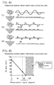
- FIG. 4(a) shows the relationship between the phase-controlled voltage a and the intermittent command signal e.
- (i) illustrates the case where the phase-control angle is about 0°
- (ii) illustrates the case where the phase-control angle is about 90°
- (iii) illustrates the case where the phase-control angle is about 120°.
- each horizontal axis is a time axis, and the time axis serves as a common measure in the respective charts.
- the phase-controlled voltage a shown in FIG. 4(a) is first inputted to the dimming control signal input section 8 of the dimming controller 7 shown in FIG. 1, and is rectified in the dimming control signal input section A 18.
- the intermittent command signal b is transmitted to the switching circuit 9 via the intermittent command signal generator 19, and thus the MOSFETs 11 and 12 of the DC-AC converter 6 are driven with the driving frequency f1 (Hz) .
- the dimming controller 7 outputs a signal for extinguishing the electrodeless fluorescent lamp 3.
- FIG. 4(b) shows the relationship between the phase-control angle and on duty ratio, and the horizontal axis represents the phase-control angle [degree] while the vertical axis represents the on duty ratio.
- (I) signifies an electric energy supply insufficient region where dimming is carried out at a deeper level by the dimmer 2, and the present inventors confirmed that in this region, a voltage applied to the fluorescent lamp 3 is low, and a phenomenon such as undesired extinguishing or flickering might occur.
- the electric energy supply insufficient region (I) covers the range of the phase-control angle equal to or higher than 120°. If the phase-control angle becomes equal to or higher than 120°, flickering is likely to occur. If the phase-control angle becomes equal to or higher than 150°, many people feel uncomfortable. And if deeper dimming is carried out, the light is undesirably extinguished. In some cases, due to variations in the characteristics of electrodeless self-ballasted fluorescent lamps, flickering does not occur even if the phase-control angle exceeds 120°; however, in order to surely prevent flickering for all the lamps, it is preferable that the electric energy supply insufficient region (I) covers the range of the phase-control angle equal to or higher than 120°.
- the on duty ratio is linearly decreased in accordance with an increase in the phase-control angle. That is, in this range, an approximate linear function relationship with a negative slope is established between the phase-control angle and the on duty ratio. Therefore, when the dimmer is operated, in this range, the light emission output of the lamp is also substantially linearly decreased in accordance with an increase in the approximate phase-control angle, and thus the dimming of the lamp can be carried out with ease.
- the on duty ratio of the intermittent command signal e is reduced to 0, and the electrodeless fluorescent lamp 3 is extinguished; therefore, a problem such as flickering or operation failure does not occur.
- R and C represent a resistor and a capacitor which are added to the IC, respectively.
- the on time width is long, even after the electrical charges of the capacitor for charge and discharge are completely discharged, the charge will not start, and the off period (minimum potential period) of the sawtooth wave c becomes long.
- the sawtooth wave is a signal resulting from the charge and discharge of electrical charges, a sufficient discharge time has to be set in order to obtain a stable sawtooth wave. Therefore, if the maximum output level of the sawtooth wave is about 4V, for example, the discharge time is preferably about 0.4 ms upon due consideration.
- the dimming controller 7 is formed so as to output a signal for extinguishing the electrodeless fluorescent lamp 3 before the operation thereof becomes unstable; thus, deep dimming (i.e., low level dimming) can be stably carried out. That is, the turn-on of the AC voltage phase-controlled in an incandescent lamp dimmer, for example, can be accurately detected so as to start the driving, and in addition, the driving can be stopped within the range in which an application voltage required for the start of operation of the fluorescent lamp is obtainable, thus achieving smooth dimming operation that causes no flickering.
- the configuration of the electrodeless self-ballasted fluorescent lamp has been described; however, the present embodiment may also be applied to an electrodeless self-ballasted discharge lamp having no fluorescent material.
- the present embodiment may be applied to a discharge lamp such as a lamp for sterilization in which no fluorescent material is applied to its discharge bulb.
- the application is not limited to general illumination but may include, for example, the operation of a lamp for emitting rays of light for a person's health, which has an action spectrum effective against erythema or effective in generating vitamin D, or a lamp for growing plants, which has an action spectrum effective in enabling photosynthesis or morphogenesis of plants.
- the configuration of the present embodiment is not limited to a self-ballasted lamp operating device, but may be applied to a discharge lamp operating device (i.e., an electrodeless discharge lamp operating device) in which the electrodeless fluorescent lamp 3 and the ballast circuit 4 are independently provided.
- a discharge lamp operating device i.e., an electrodeless discharge lamp operating device
- the electrodeless fluorescent lamp 3 and the ballast circuit 4 are independently provided.
- the frequency in the present embodiment is in a relatively low frequency range of 1 MHz or less (e.g., 50 kHz to 500 kHz) as compared with an ISM frequency band of 13.56 MHz or several MHz which is practically and generally utilized.
- the frequency in such a low frequency range is used because of the following reasons.
- a noise filter for suppressing line noise generated from a high-frequency power supply circuit within the ballast circuit is increased in size, which undesirably increases the volume of the high-frequency power supply circuit.
- a noise filter for suppressing line noise generated from a high-frequency power supply circuit within the ballast circuit is increased in size, which undesirably increases the volume of the high-frequency power supply circuit.
- the lamp is operated in a frequency range of about 1 MHz to 50 kHz, inexpensive general-purpose products, which are used as electronic components for general electronic equipment, can be utilized as components for forming the high-frequency power supply circuit; in addition, since the use of small-sized components is enabled, not only cost reduction but also size reduction can be achieved, thus obtaining considerable advantages.
- the electrodeless fluorescent lamp of the present embodiment does not have to be operated at a frequency of 1 MHz or less, but may alternatively be operated in a frequency range of 13.56 MHz or several MHz, for example.
- a second embodiment of the present invention will be described with reference to FIG. 5.
- a sawtooth wave generator 20 for detecting the turn-on of a phase-controlled voltage is formed differently from the counterpart in the first embodiment, and can be formed inexpensively without using any IC in the configuration of the present embodiment.
- FIG. 5 shows a circuit for detecting the turn-on of a phase-controlled voltage in the present embodiment, and in particular shows the configuration of the sawtooth wave generator 20. It should be noted that the same constituting elements as the counterparts described in the first embodiment are identified by the same reference characters, and the further description thereof will be omitted.
- the sawtooth wave generator 20 shown in FIG. 5 has: a differentiating circuit 201; a diode 202; a transistor 203; and a capacitor 204, and the differentiating circuit 201 includes a capacitor and a resistor.
- the sawtooth wave generator 20 is connected to a dimming control signal input section A 18 via a photo coupler 19, the dimming control signal input section A 18 is connected to a dimmer 2, and the dimmer 2 is electrically connected to a commercial power supply 1 .
- a transistor may be provided between the photo coupler 19 and the differentiating circuit 201 for current amplification.
- the differentiating circuit 201 is connected to a collector terminal of the transistor of the photo coupler 19, which generates a pulse wave synchronized with the turn-on and turn-off of a phase-controlled AC voltage.
- An output terminal of the differentiating circuit 201 is connected with an anode of the diode 202, while a cathode of the diode 202 is connected with a base terminal of the transistor 203 for discharge.
- the capacitor 204 for charge and discharge is connected.
- the emitter terminal of the transistor 203 for discharge is connected, in series, with three diodes 205 for potential adjustment.
- anode terminals of the diodes 205 for potential adjustment are connected to the emitter terminal of the transistor 203 for discharge. Due to such a configuration, the sawtooth wave generator 20 can generate a sawtooth wave synchronized with the turn-on of the phase-controlled voltage.
- an output signal of the differentiating circuit 201 becomes a differential wave synchronized with a rising edge and a falling edge of the pulse wave, and only the differential wave synchronized with the rising edge by using the diode 202 with a low leakage current is inputted to the base terminal of the transistor 203.
- the capacitor 204 connected between the collector terminal and emitter terminal of the transistor 203 repeats charge and discharge using, as a trigger, the rising edge of the pulse wave from the photo coupler 19, thus allowing the generation of a sawtooth wave.
- the emitter terminal of the transistor 203 for discharge is connected with three diodes 205 for potential adjustment, each having a forward voltage of about 0.6V, for example, the minimum potential of the sawtooth wave becomes about 1.8V, thus making it possible to raise the level of a base voltage of the sawtooth wave. Furthermore, since the charge and discharge is carried out using, as a trigger, the signal of the turn-on of the phase-controlled voltage, the sawtooth wave maintains a constant waveform even if the conduction angle of the phase-controlled voltage is changed.
- the sawtooth wave generator 20 it becomes possible to implement the sawtooth wave generator 20 with inexpensive components without using any expensive IC components.
- three diodes 205 for potential adjustment are used, four or more diodes 205 may alternatively be used, or one or two diodes 205 may optionally be used.
- a constant-voltage power supply may be used instead of the diode. It should be noted that, more favorably, a buffer circuit is added, thus increasing output impedance.
- FIG. 6 shows a circuit diagram of a device for operating a discharge lamp having electrodes according to an embodiment for reference for purpose of comparison with the embodiments of the present invention.
- the embodiment for reference differs from the above-described first embodiment in that a discharge bulb 17' has electrodes, and that a load resonant circuit is differently formed for the operation of a fluorescent lamp 3' having electrodes.
- a discharge bulb 17' has electrodes
- a load resonant circuit is differently formed for the operation of a fluorescent lamp 3' having electrodes.
- an LC resonant circuit including: a fluorescent lamp 3'; a resonant inductor 13; a resonant capacitor 15; and a capacitor 14 for resonance and preheat is connected between a drain terminal and a source terminal of a MOSFET 12.
- the temperature of each electrode is increased due to a preheat current flowing to the two electrodes within the discharge bulb 17', and if the generation of thermion from the electrodes is easily allowed, the discharge bulb 17' causes a breakdown and starts discharge. Once the discharge bulb 17' has started the discharge, the current flowing through the discharge bulb 17' is limited by the resonant inductor 15, thus maintaining the stable discharge.
- a dimming controller 7 of the embodiment for reference are similar to those of the dimming controller 7 of the first embodiment.
- the discharge lamp operating device of the embodiment for reference is different from that of the present invention.
- the ballast circuit 4 for carrying out intermittent driving is not very suitable for use in combination with the fluorescent lamp 3' having electrodes according to the embodiment for reference, but is more suitable for use in combination with the electrodeless fluorescent lamp 3 of the first and second embodiments. This is because since the intermittent driving is an operation that repeats turning-on and turning-off, the electrodes of the fluorescent lamp 3' are severely worn out, thus causing the problem that their lives are shortened. In the present invention, since the electrodeless discharge lamp 3 has no electrode to begin with, such a problem will not occur.
- the dimming controller 7 is formed so as to output a signal for synchronizing the timing of the turn-on of the phase-controlled voltage with that of the operation of the lamp intermittently driven by the DC-AC converter 6 because dimming operation can be carried out more favorably if the synchronization is achieved.
- a ballast circuit 4' carries out intermittent driving, but is not intended to synchronize the timing of the turn-on of the phase-controlled voltage with that of the operation of the lamp intermittently driven by a DC-AC converter 6.
- the configuration shown in FIG. 7 differs from that of the first embodiment in that a dimming controller 7' is formed so as to generate a dimming control signal and send a dimming command signal to the DC-AC converter (inverter circuit) 6.
- the dimming controller 7' is made up of: a dimming signal generator 74; and a dimming command signal section 10 for sending the dimming command signal to the DC-AC converter 6.
- An output from a dimmer 2, phase-controlled by a triac, is half-wave rectified through a half-wave rectifier 71, a comparator 73 compares the resulting output voltage (120 Hz) with an output voltage from a triangular wave generator 72 for generating a reference voltage with a reference frequency (120 Hz), and then the comparator 73 outputs a pulse shape dimming signal with a constant frequency.
- the dimming signal is sent to the DC-AC converter 6 via the dimming command signal section 10, and the dimming of the electrodeless fluorescent lamp 3 is carried out while the on time and off time of the DC-AC converter 6 being changed.
- the electrodeless fluorescent lamp is used as a discharge lamp
- the switching frequency f1 of the inverter circuit is 200 kHz
- MOSFETs are used as switching elements.
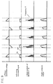
- FIG. 8 shows experimental results obtained from the configuration shown in FIG. 7.
- the operation and characteristic of the discharge lamp operating device shown in FIG. 7 will be described.
- FIG. 8 illustrates waveform charts showing waveforms a through d, in which each horizontal axis is a time axis, and the time axis serves as a common measure in the respective waveform charts.
- a represents the waveform of the voltage phase-controlled in the dimmer 2 .
- the conduction angle of the triac of the dimmer 2 is close to ⁇ , and therefore, considerably deep dimming is carried out.
- b represents the dimming command signal that is sent from the dimming controller 7 to the DC-AC converter 6 when the phase-controlled voltage such as one having the waveform a in FIG. 8 is inputted to the ballast circuit 4 .
- the turn-on of the phase-controlled voltage is not synchronized with the turn-on of the dimming command signal. That is, after the turn-on of the phase-controlled voltage, the sending of the dimming command signal from the dimming controller 7 to the DC-AC converter is delayed by a time period ⁇ t . Since a large amount of energy is required for the start of operation of the electrodeless fluorescent lamp 3, a large drain current flows through each of the MOSFETs 11 and 12 at the moment of operation of the lamp as indicated by the waveform c in FIG. 8.
- the turn-on of the dimming command signal is delayed from that of the phase-controlled voltage by the time period ⁇ t , the rising of the drain current of each of the MOSFETs 11 and 12 is delayed.
- a period of time during which a high-frequency electric power is supplied to the electrodeless fluorescent lamp 3 and a period of time for light emission are reduced accordingly, and in addition, the driving of the DC-AC converter is stopped in the state where the phase-controlled voltage right after the turn-on thereof is at a highest level; consequently, a reduction in the light emission output of the electrodeless discharge lamp is significant.
- the drain current of each of the MOSFETs 11 and 12 is decreased, and as a result, the high-frequency electric power supplied to the electrodeless fluorescent lamp 3 is reduced, and a threshold state where the lamp is operated or extinguished is nearly reached.
- the dimming controller is formed so as to output a signal for extinguishing the lamp before the operation thereof becomes unstable, and therefore, smooth dimming can be carried out. Furthermore, by achieving the synchronization in this case, it becomes possible to reduce the possibility of reaching the unstable state even if deeper dimming is carried out, and the range in which the actual brightness is variable (i.e., the range of the actual dimming) can be extended accordingly; as a result, a more outstanding dimmable electrodeless discharge lamp can be implemented, thus providing a preferred embodiment.
- the discharge lamp operating device e.g., the electrodeless self-ballasted fluorescent lamp
- the timing of the turn-on of the phase-controlled voltage is synchronized with that of the turn-on of the intermittent command signal for intermittently driving the DC-AC converter 6, and the fluorescent lamp can be extinguished before the operation of the discharge lamp becomes unstable due to the approach of the conduction angle of the phase-controlled voltage to ⁇ and the resulting reduction of the voltage applied to the lamp. Consequently, stable dimming operation can be achieved.
- the dimming controller is formed so as to output a signal for extinguishing the electrodeless fluorescent lamp (or discharge lamp) before the operation of the electrodeless fluorescent lamp (or discharge lamp) becomes unstable, thus making it possible to achieve smooth dimming operation that causes no flickering.
- the present invention is effective where it is applied to electrodeless discharge lamps, and the industrial applicability of the present invention is excellent in that an electrodeless self-ballasted fluorescent lamp connected to a dimmer, in particular, can be smoothly dimmed without causing any flickering.
Landscapes
- Engineering & Computer Science (AREA)
- Power Engineering (AREA)
- Discharge-Lamp Control Circuits And Pulse- Feed Circuits (AREA)
- Circuit Arrangements For Discharge Lamps (AREA)
Applications Claiming Priority (3)
| Application Number | Priority Date | Filing Date | Title |
|---|---|---|---|
| JP2002167580 | 2002-06-07 | ||
| JP2002167580 | 2002-06-07 | ||
| PCT/JP2003/007234 WO2003105541A1 (ja) | 2002-06-07 | 2003-06-06 | 無電極電球形蛍光ランプおよび放電ランプ点灯装置 |
Publications (1)
| Publication Number | Publication Date |
|---|---|
| EP1513377A1 true EP1513377A1 (de) | 2005-03-09 |
Family
ID=29727666
Family Applications (1)
| Application Number | Title | Priority Date | Filing Date |
|---|---|---|---|
| EP03730856A Withdrawn EP1513377A1 (de) | 2002-06-07 | 2003-06-06 | Fluoreszenzlampe des elektrodenlosen glühbirnentyps und entladungslampenbeleuchtungs einrichtung |
Country Status (6)
| Country | Link |
|---|---|
| US (1) | US6977472B2 (de) |
| EP (1) | EP1513377A1 (de) |
| JP (1) | JPWO2003105541A1 (de) |
| CN (1) | CN1596565A (de) |
| AU (1) | AU2003242025A1 (de) |
| WO (1) | WO2003105541A1 (de) |
Families Citing this family (56)
| Publication number | Priority date | Publication date | Assignee | Title |
|---|---|---|---|---|
| WO2004110110A1 (ja) * | 2003-06-04 | 2004-12-16 | Matsushita Electric Industrial Co., Ltd. | 放電ランプ点灯装置 |
| US7211966B2 (en) * | 2004-07-12 | 2007-05-01 | International Rectifier Corporation | Fluorescent ballast controller IC |
| GB2418786B (en) * | 2004-10-01 | 2006-11-29 | Energy Doubletree Ltd E | Dimmable lighting system |
| US7126287B2 (en) * | 2004-10-16 | 2006-10-24 | Osram Sylvania Inc. | Lamp with integral voltage converter having phase-controlled dimming circuit with fuse-resistor network for reducing RMS load voltage |
| DE102005027015A1 (de) * | 2005-06-10 | 2006-12-14 | Patent-Treuhand-Gesellschaft für elektrische Glühlampen mbH | Schaltungsanordnung und Verfahren zur netzspannungsabhängigen Leistungsregelung eines elektronischen Geräts, insbesondere eines elektronischen Vorschaltgeräts |
| US7521874B2 (en) * | 2005-10-12 | 2009-04-21 | International Rectifier Corporation | Dimmable ballast control integrated circuit |
| US7902769B2 (en) * | 2006-01-20 | 2011-03-08 | Exclara, Inc. | Current regulator for modulating brightness levels of solid state lighting |
| US8558470B2 (en) * | 2006-01-20 | 2013-10-15 | Point Somee Limited Liability Company | Adaptive current regulation for solid state lighting |
| US8441210B2 (en) * | 2006-01-20 | 2013-05-14 | Point Somee Limited Liability Company | Adaptive current regulation for solid state lighting |
| US7642735B2 (en) * | 2006-09-05 | 2010-01-05 | Microchip Technology Incorporated | Using pulse density modulation for controlling dimmable electronic lighting ballasts |
| US8193719B2 (en) * | 2006-09-05 | 2012-06-05 | Microchip Technology Incorporated | Using pulse density modulation for controlling dimmable electronic lighting ballasts |
| KR101336285B1 (ko) | 2007-02-13 | 2013-12-03 | 삼성디스플레이 주식회사 | 램프 구동회로, 인버터 보드 및 상기한 인버터 보드를표시장치 |
| JP2009032471A (ja) * | 2007-07-26 | 2009-02-12 | Panasonic Electric Works Co Ltd | 放電灯点灯装置及び照明器具 |
| DE102007057581A1 (de) * | 2007-11-28 | 2009-06-04 | Fachhochschule Aachen | Hochfrequenzlampe und Verfahren zu deren Betrieb |
| JP5153365B2 (ja) * | 2008-01-31 | 2013-02-27 | 株式会社オーク製作所 | マイクロ波励起放電ランプの点灯方法 |
| WO2009101544A2 (en) * | 2008-02-12 | 2009-08-20 | Philips Intellectual Property & Standards Gmbh | Control circuit of a dimmer assembly for dimming an energy-saving lamp |
| TW200949145A (en) * | 2008-05-21 | 2009-12-01 | Gigno Technology Co Ltd | Light-emitting apparatus and dimming method |
| EP2175700A1 (de) * | 2008-10-09 | 2010-04-14 | Chuan Shih Industrial Co., Ldt. | Dimmkreislauf für Entladelampe mit Ausschaltfähigkeit bei niedriger Stromversorgung |
| US8232742B2 (en) | 2008-11-27 | 2012-07-31 | Arkalumen Inc. | Method, apparatus and computer-readable media for controlling lighting devices |
| CN101848590A (zh) * | 2009-03-27 | 2010-09-29 | 上海豪迈净能科技有限公司 | 一种电子镇流电路 |
| WO2011084525A1 (en) | 2009-12-16 | 2011-07-14 | Exclara, Inc. | Adaptive current regulation for solid state lighting |
| US8564214B2 (en) | 2010-05-11 | 2013-10-22 | Arkalumen Inc. | Circuits for sensing current levels within lighting apparatus |
| US8618744B2 (en) * | 2010-05-11 | 2013-12-31 | Arkalumen Inc. | Control apparatus and lighting apparatus incorporating control apparatus |
| US9086435B2 (en) | 2011-05-10 | 2015-07-21 | Arkalumen Inc. | Circuits for sensing current levels within a lighting apparatus incorporating a voltage converter |
| US9089024B2 (en) | 2010-05-11 | 2015-07-21 | Arkalumen Inc. | Methods and apparatus for changing a DC supply voltage applied to a lighting circuit |
| JP5043213B2 (ja) * | 2010-08-23 | 2012-10-10 | シャープ株式会社 | Led駆動回路及びこれを用いたled照明灯具 |
| US9192009B2 (en) | 2011-02-14 | 2015-11-17 | Arkalumen Inc. | Lighting apparatus and method for detecting reflected light from local objects |
| US8941308B2 (en) | 2011-03-16 | 2015-01-27 | Arkalumen Inc. | Lighting apparatus and methods for controlling lighting apparatus using ambient light levels |
| US8939604B2 (en) | 2011-03-25 | 2015-01-27 | Arkalumen Inc. | Modular LED strip lighting apparatus |
| JP2013021454A (ja) * | 2011-07-08 | 2013-01-31 | Sony Corp | 撮像装置及び固体撮像装置の保護装置 |
| US9060400B2 (en) | 2011-07-12 | 2015-06-16 | Arkalumen Inc. | Control apparatus incorporating a voltage converter for controlling lighting apparatus |
| US9209008B2 (en) | 2012-11-26 | 2015-12-08 | Lucidity Lights, Inc. | Fast start induction RF fluorescent light bulb |
| US10529551B2 (en) | 2012-11-26 | 2020-01-07 | Lucidity Lights, Inc. | Fast start fluorescent light bulb |
| US20140145618A1 (en) * | 2012-11-26 | 2014-05-29 | Lucidity Lights, Inc. | Dimmable induction rf fluorescent light bulb |
| US10128101B2 (en) | 2012-11-26 | 2018-11-13 | Lucidity Lights, Inc. | Dimmable induction RF fluorescent lamp with reduced electromagnetic interference |
| US20140375203A1 (en) | 2012-11-26 | 2014-12-25 | Lucidity Lights, Inc. | Induction rf fluorescent lamp with helix mount |
| US20140145615A1 (en) * | 2012-11-26 | 2014-05-29 | Lucidity Lights, Inc. | Induction rf fluorescent light bulb with burst-mode dimming |
| US9524861B2 (en) | 2012-11-26 | 2016-12-20 | Lucidity Lights, Inc. | Fast start RF induction lamp |
| US10141179B2 (en) | 2012-11-26 | 2018-11-27 | Lucidity Lights, Inc. | Fast start RF induction lamp with metallic structure |
| CN104937693B (zh) * | 2012-11-26 | 2018-02-02 | 明灯有限公司 | 感应rf荧光灯 |
| US9245734B2 (en) | 2012-11-26 | 2016-01-26 | Lucidity Lights, Inc. | Fast start induction RF fluorescent lamp with burst-mode dimming |
| US9305765B2 (en) | 2012-11-26 | 2016-04-05 | Lucidity Lights, Inc. | High frequency induction lighting |
| US9460907B2 (en) | 2012-11-26 | 2016-10-04 | Lucidity Lights, Inc. | Induction RF fluorescent lamp with load control for external dimming device |
| USD745981S1 (en) | 2013-07-19 | 2015-12-22 | Lucidity Lights, Inc. | Inductive lamp |
| USD745982S1 (en) | 2013-07-19 | 2015-12-22 | Lucidity Lights, Inc. | Inductive lamp |
| USD747507S1 (en) | 2013-08-02 | 2016-01-12 | Lucidity Lights, Inc. | Inductive lamp |
| USD747009S1 (en) | 2013-08-02 | 2016-01-05 | Lucidity Lights, Inc. | Inductive lamp |
| DE112015004202T5 (de) * | 2014-09-15 | 2017-06-01 | Dialog Semiconductor Inc. | Mehrfachmodus-steuerung für eine festkörperbeleuchtung |
| US10225904B2 (en) | 2015-05-05 | 2019-03-05 | Arkalumen, Inc. | Method and apparatus for controlling a lighting module based on a constant current level from a power source |
| US9775211B2 (en) | 2015-05-05 | 2017-09-26 | Arkalumen Inc. | Circuit and apparatus for controlling a constant current DC driver output |
| US9992829B2 (en) | 2015-05-05 | 2018-06-05 | Arkalumen Inc. | Control apparatus and system for coupling a lighting module to a constant current DC driver |
| US10568180B2 (en) | 2015-05-05 | 2020-02-18 | Arkalumen Inc. | Method and apparatus for controlling a lighting module having a plurality of LED groups |
| US9992836B2 (en) | 2015-05-05 | 2018-06-05 | Arkawmen Inc. | Method, system and apparatus for activating a lighting module using a buffer load module |
| USD854198S1 (en) | 2017-12-28 | 2019-07-16 | Lucidity Lights, Inc. | Inductive lamp |
| US10236174B1 (en) | 2017-12-28 | 2019-03-19 | Lucidity Lights, Inc. | Lumen maintenance in fluorescent lamps |
| US11382192B2 (en) | 2019-02-08 | 2022-07-05 | Lucidity Lights, Inc. | Preferred lighting spectrum and color shifting circadian lamps |
Family Cites Families (12)
| Publication number | Priority date | Publication date | Assignee | Title |
|---|---|---|---|---|
| JPH03233894A (ja) * | 1990-02-07 | 1991-10-17 | Hitachi Ltd | 放電灯点灯装置 |
| US5561351A (en) * | 1992-10-14 | 1996-10-01 | Diablo Research Corporation | Dimmer for electrodeless discharge lamp |
| US5604411A (en) * | 1995-03-31 | 1997-02-18 | Philips Electronics North America Corporation | Electronic ballast having a triac dimming filter with preconditioner offset control |
| JPH10208702A (ja) * | 1996-08-28 | 1998-08-07 | General Electric Co <Ge> | コンパクト蛍光ランプ |
| JPH11111486A (ja) | 1997-09-30 | 1999-04-23 | Toshiba Lighting & Technology Corp | 放電灯点灯装置および照明装置 |
| JP2001313196A (ja) | 2000-02-25 | 2001-11-09 | Toshiba Lighting & Technology Corp | 電球形蛍光ランプ、放電ランプ点灯装置および照明装置 |
| US6486616B1 (en) | 2000-02-25 | 2002-11-26 | Osram Sylvania Inc. | Dual control dimming ballast |
| JP3322261B2 (ja) * | 2000-03-27 | 2002-09-09 | 松下電器産業株式会社 | 放電ランプ点灯装置 |
| US6504322B2 (en) * | 2000-04-18 | 2003-01-07 | Matsushita Electric Industrial Co., Ltd. | Discharge lamp operating apparatus |
| JP2002015892A (ja) * | 2000-06-28 | 2002-01-18 | Matsushita Electric Ind Co Ltd | 放電ランプ点灯装置 |
| JP3846175B2 (ja) | 2000-10-30 | 2006-11-15 | 松下電工株式会社 | 無電極放電灯点灯装置 |
| US6392366B1 (en) * | 2001-09-19 | 2002-05-21 | General Electric Company | Traic dimmable electrodeless fluorescent lamp |
-
2003
- 2003-06-06 AU AU2003242025A patent/AU2003242025A1/en not_active Abandoned
- 2003-06-06 US US10/494,652 patent/US6977472B2/en not_active Expired - Fee Related
- 2003-06-06 WO PCT/JP2003/007234 patent/WO2003105541A1/ja not_active Application Discontinuation
- 2003-06-06 CN CNA038016435A patent/CN1596565A/zh active Pending
- 2003-06-06 EP EP03730856A patent/EP1513377A1/de not_active Withdrawn
- 2003-06-06 JP JP2004512466A patent/JPWO2003105541A1/ja active Pending
Non-Patent Citations (1)
| Title |
|---|
| See references of WO03105541A1 * |
Also Published As
| Publication number | Publication date |
|---|---|
| US20040263093A1 (en) | 2004-12-30 |
| US6977472B2 (en) | 2005-12-20 |
| CN1596565A (zh) | 2005-03-16 |
| JPWO2003105541A1 (ja) | 2005-12-15 |
| AU2003242025A1 (en) | 2003-12-22 |
| WO2003105541A1 (ja) | 2003-12-18 |
Similar Documents
| Publication | Publication Date | Title |
|---|---|---|
| US6977472B2 (en) | Electrodeless self-ballasted fluorescent lamp and discharge lamp operating device | |
| US6998792B2 (en) | Electrodeless discharge lamp lighting device, light bulb type electrodeless fluorescent lamp and discharge lamp lighting device | |
| JP4134037B2 (ja) | 無電極放電ランプ点灯装置、電球形無電極蛍光ランプおよび放電ランプ点灯装置 | |
| US6828740B2 (en) | Electrodeless discharge lamp operating apparatus, electrodeless compact self-ballasted fluorescent lamp and discharge lamp operating apparatus | |
| US9220159B2 (en) | Electronic ballast | |
| US8228002B2 (en) | Hybrid light source | |
| JP6031669B2 (ja) | 低出力照明ユニットを動作させる回路装置及びそれを動作させる方法 | |
| EP1768468A2 (de) | Beleuchtungsanordnung mit Entladungslampe hoher Intensität, und Beleuchtungsgerät | |
| EP0765108A3 (de) | Anordnung zum Betreiben einer Starkstromentladungslampe | |
| JP2002231471A (ja) | Led点灯装置及び照明装置 | |
| KR20100098688A (ko) | 디밍가능한 광 생성 디바이스 | |
| JP2003317989A (ja) | 無電極放電ランプ点灯装置、電球形無電極蛍光ランプおよび放電ランプ点灯装置 | |
| JP2003031390A (ja) | 直線形ランプにおける光条の電子的除去 | |
| KR100451358B1 (ko) | 마이크로파를 이용한 조명장치의 전원 공급 장치 | |
| TWI287947B (en) | Light modulation apparatus for excimer discharge lamp | |
| US20060017401A1 (en) | Dimming control techniques using self-excited gate circuits | |
| JP3758342B2 (ja) | 放電灯点灯装置 | |
| WO2004110110A1 (ja) | 放電ランプ点灯装置 | |
| KR20130046400A (ko) | 조광기 도통각 검출 회로 및 이를 포함하는 시스템 | |
| JPH09283292A (ja) | 無電極放電灯点灯装置および照明装置 | |
| JP2004215463A (ja) | 電源装置、バックライト装置、および液晶表示装置 | |
| JP3945715B2 (ja) | 照明用点灯装置 | |
| JPH11251081A (ja) | 放電ランプ点灯装置および照明装置 | |
| JP2012048981A (ja) | 照明点灯装置及びそれを用いた照明器具 | |
| JP2002043079A (ja) | 無電極放電灯点灯装置 |
Legal Events
| Date | Code | Title | Description |
|---|---|---|---|
| PUAI | Public reference made under article 153(3) epc to a published international application that has entered the european phase |
Free format text: ORIGINAL CODE: 0009012 |
|
| 17P | Request for examination filed |
Effective date: 20040427 |
|
| AK | Designated contracting states |
Kind code of ref document: A1 Designated state(s): AT BE BG CH CY CZ DE DK EE ES FI FR GB GR HU IE IT LI LU MC NL PT RO SE SI SK TR |
|
| AX | Request for extension of the european patent |
Extension state: AL LT LV MK |
|
| DAX | Request for extension of the european patent (deleted) | ||
| RBV | Designated contracting states (corrected) |
Designated state(s): DE FR GB IT |
|
| STAA | Information on the status of an ep patent application or granted ep patent |
Free format text: STATUS: THE APPLICATION HAS BEEN WITHDRAWN |
|
| 18W | Application withdrawn |
Effective date: 20060328 |