EP1513175A2 - Kippschalter und Verfahren zur Herstellung eines zweistufigen Kippschalters - Google Patents
Kippschalter und Verfahren zur Herstellung eines zweistufigen Kippschalters Download PDFInfo
- Publication number
- EP1513175A2 EP1513175A2 EP04018833A EP04018833A EP1513175A2 EP 1513175 A2 EP1513175 A2 EP 1513175A2 EP 04018833 A EP04018833 A EP 04018833A EP 04018833 A EP04018833 A EP 04018833A EP 1513175 A2 EP1513175 A2 EP 1513175A2
- Authority
- EP
- European Patent Office
- Prior art keywords
- actuating
- toggle switch
- guide plate
- switch according
- tappet
- Prior art date
- Legal status (The legal status is an assumption and is not a legal conclusion. Google has not performed a legal analysis and makes no representation as to the accuracy of the status listed.)
- Granted
Links
- 238000004519 manufacturing process Methods 0.000 title claims abstract description 10
- 238000001746 injection moulding Methods 0.000 claims description 3
- 230000000994 depressogenic effect Effects 0.000 description 4
- 238000003825 pressing Methods 0.000 description 2
- 230000000881 depressing effect Effects 0.000 description 1
- 238000002347 injection Methods 0.000 description 1
- 239000007924 injection Substances 0.000 description 1
- 230000013011 mating Effects 0.000 description 1
- 239000002184 metal Substances 0.000 description 1
- 238000000034 method Methods 0.000 description 1
- 125000006850 spacer group Chemical group 0.000 description 1
Images

Classifications
-
- H—ELECTRICITY
- H01—ELECTRIC ELEMENTS
- H01H—ELECTRIC SWITCHES; RELAYS; SELECTORS; EMERGENCY PROTECTIVE DEVICES
- H01H21/00—Switches operated by an operating part in the form of a pivotable member acted upon directly by a solid body, e.g. by a hand
- H01H21/02—Details
- H01H21/18—Movable parts; Contacts mounted thereon
- H01H21/22—Operating parts, e.g. handle
-
- H—ELECTRICITY
- H01—ELECTRIC ELEMENTS
- H01H—ELECTRIC SWITCHES; RELAYS; SELECTORS; EMERGENCY PROTECTIVE DEVICES
- H01H19/00—Switches operated by an operating part which is rotatable about a longitudinal axis thereof and which is acted upon directly by a solid body external to the switch, e.g. by a hand
- H01H19/54—Switches operated by an operating part which is rotatable about a longitudinal axis thereof and which is acted upon directly by a solid body external to the switch, e.g. by a hand the operating part having at least five or an unspecified number of operative positions
- H01H19/60—Angularly-movable actuating part carrying no contacts
- H01H19/635—Contacts actuated by rectilinearly-movable member linked to operating part, e.g. by pin and slot
-
- H—ELECTRICITY
- H01—ELECTRIC ELEMENTS
- H01H—ELECTRIC SWITCHES; RELAYS; SELECTORS; EMERGENCY PROTECTIVE DEVICES
- H01H21/00—Switches operated by an operating part in the form of a pivotable member acted upon directly by a solid body, e.g. by a hand
- H01H21/02—Details
- H01H21/18—Movable parts; Contacts mounted thereon
- H01H21/22—Operating parts, e.g. handle
- H01H2021/225—Operating parts, e.g. handle with push-pull operation, e.g. which can be pivoted in both directions by pushing or pulling on the same extremity of the operating member
-
- H—ELECTRICITY
- H01—ELECTRIC ELEMENTS
- H01H—ELECTRIC SWITCHES; RELAYS; SELECTORS; EMERGENCY PROTECTIVE DEVICES
- H01H2233/00—Key modules
- H01H2233/002—Key modules joined to form button rows
- H01H2233/004—One molded part
- H01H2233/006—Separating individual keys after mounting
-
- H—ELECTRICITY
- H01—ELECTRIC ELEMENTS
- H01H—ELECTRIC SWITCHES; RELAYS; SELECTORS; EMERGENCY PROTECTIVE DEVICES
- H01H23/00—Tumbler or rocker switches, i.e. switches characterised by being operated by rocking an operating member in the form of a rocker button
- H01H23/003—Tumbler or rocker switches, i.e. switches characterised by being operated by rocking an operating member in the form of a rocker button with more than one electrically distinguishable condition in one or both positions
-
- H—ELECTRICITY
- H01—ELECTRIC ELEMENTS
- H01H—ELECTRIC SWITCHES; RELAYS; SELECTORS; EMERGENCY PROTECTIVE DEVICES
- H01H2300/00—Orthogonal indexing scheme relating to electric switches, relays, selectors or emergency protective devices covered by H01H
- H01H2300/01—Application power window
-
- Y—GENERAL TAGGING OF NEW TECHNOLOGICAL DEVELOPMENTS; GENERAL TAGGING OF CROSS-SECTIONAL TECHNOLOGIES SPANNING OVER SEVERAL SECTIONS OF THE IPC; TECHNICAL SUBJECTS COVERED BY FORMER USPC CROSS-REFERENCE ART COLLECTIONS [XRACs] AND DIGESTS
- Y10—TECHNICAL SUBJECTS COVERED BY FORMER USPC
- Y10T—TECHNICAL SUBJECTS COVERED BY FORMER US CLASSIFICATION
- Y10T29/00—Metal working
- Y10T29/49—Method of mechanical manufacture
- Y10T29/49002—Electrical device making
- Y10T29/49105—Switch making
Definitions
- the invention relates to a toggle switch and a method for manufacturing a toggle switch, in particular a two-stage toggle switch.
- toggle switches in which the tilting or rotational movement a rocker switch in a linear motion to close one or more electrical contacts is implemented.
- the object of the invention is to present a cost-effective toggle switch, which ensures a safe switching action.
- a guide plate with at least one receptacle in which at least one Actuating plunger is guided linearly displaceable, wherein the arm of the rocker switch can transmit a force to the actuating tappet, and a switch unit, on which the actuating tappet can act to make an electrical contact close it is provided that the guide plate and the actuating plunger each have a breaking edge along which they are prior to assembly of the Toggle switch were integrally connected.
- two webs per actuating tappet are preferred intended.
- the actuating tappets. So are in a projection into the Level of the guide plate already arranged in its desired position. at A force acting in the direction of recording, they are automatically correct positioned. Such a unit can be easily in an injection molding process finished.
- the inclusion of the guide plate advantageously has in the region of the web Recess, which is designed so that residues of the web not with a wall come in contact with the recording.
- the actuating plunger in Region of the web have a recess which is formed so that residues of the bridge do not come into contact with the actuating plunger. This will ensures that the remains of the bridge the movement of the actuating plunger in not hinder the recording.
- through the wall of the recording be provided outside the recess an almost play-free leadership.
- a latching element be provided after the pressing of the actuating plunger in the Recording forms an end stop for the lower end of the actuating plunger and thus secures the actuating tappet against falling out of the guide plate.
- a plurality of actuating tappets are provided which in corresponding Shooting arranged and a corresponding number of switch units assigned.
- a connecting element be provided, the actuating tappet at the upper end with each other combines.
- the upper end of the actuating plunger is rounded, and the connecting element rests on the upper ends. So can the connecting element perform a tilting movement with which the height differences between a depressed and an unconfirmed position located actuating tappet be balanced.
- This can be e.g. a two- or four-stage toggle switch for an electrical Realize window lift of a vehicle. With a tilting movement in two directions can be e.g. respond to four switching stages.
- For a four-step Switch has the rocker preferably two arms. Each of the two arms can then, e.g. over one or more fasteners that are on the top The ends of the actuating tappets rest, depress two actuating tappets and thus realize two switching states.
- the invention also relates to a method for producing a toggle switch.
- the guide plate and the actuating plunger are integral manufactured together, and the actuating plunger is by a force pressed into the receptacle of the guide plate and in this case of the guide plate solved.
- the guide plate and the actuating plunger are integrally in an injection molding process made of a suitable plastic.
- FIG 1 shows a toggle switch 10 with a switch button 12, which with a two-armed rocker 14 is connected.
- the rocker 14 is about an axis 16 tiltable in two directions, which is illustrated by the two arrows in Figure 1 is. This tilting movement is, as described below, in one linear movement in a switching direction z implemented, the closing of a or more electrical contacts.
- Each of the two arms 18 of the rocker switch 14 lies on a single connecting element 20, which is formed here from a sheet metal.
- the connecting element 20 in turn lies on rounded upper ends 22 (based on the Switching direction z) of actuating tappets 24.
- Each actuating tappet 24 is in a receptacle 26 a guide plate 28 out.
- the shots 26 leave only a linear movement of the actuating plunger 24 in the in Figures 1 and 2 with an arrow designated switching direction z and in the opposite Direction to.
- On the side remote from the connecting element 20 side are the lower ends of the actuating tappet 24 in contact with switch units, here are formed by switching domes 30 of a conventional switching mat 32.
- One electrical contact is closed when a switching dome 30 with a contact on its underside a corresponding mating contact at the base of the switching mat 32 touched (not shown).
- the switching domes 30 are elastic Connections 34 connected to the base of the switching mat 32 and elastic so biased that they are anxious, in the open position shown in Figure 1 to return.
- the guide plate 28 has a middle planar portion 40 and to the Outer sides in the direction of the switching mat 32 pointing spacer sections 38th
- the tilting or rotational movement of the switching key 12 is via the connecting element 20 and the actuating tappet 24 which guided in the receptacles 26 are converted into a purely linear movement, so that the switching dome 30 always only be loaded in z-direction.
- the toggle switch 10 is shown in Figure 1 in an unactuated position. In this is the rocker 14 in equilibrium, so that none of the actuating tappet 24 loaded and deflected from its initial position shown. none the switching dome 30 is depressed, so that all electrical contacts of the Safety mat 32 are open. To prevent rattling, every switching dome is 30, however, biased by about 0.2 mm. Basically slightly biased the rocker 14 and the actuating plunger 24th
- the toggle switch 10 shown is a four-stage switch as e.g. for one power windows of a vehicle can be used. In this case would only the upper part of the switch button 12 via a cowling 36 of the Vehicle, e.g. a door panel, sticking out.
- the arms 18 of the rocker 14 are located on the connecting element 20 respectively offset from the middle between two actuating tappets 24, so that the Actuating forces for the two respective associated switching domes 30 different are.
- About the contact point of the arms 18 on the connecting element 20th can the force required to trigger the various switching states necessary is, set.
- the rounding at the upper end 22 of the actuating tappet 24 may be adjust the connecting element 20 in its position when one or more of the Actuating plunger 24 for closing the electrical contacts in their recording 26 are pressed into it.
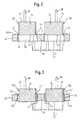
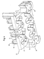
- the guide plate 28 and the actuating tappet 24 are injection molded manufactured as a one-piece unit. This unit is in FIG. 2 shown.
- the actuating tappets 24 are at a lower end 42 on two sides via webs 44 formed integrally with them and with the guide plate 28 are, with an upper end 46 of a wall 48 of the receptacle 26 in the guide plate 28 connected.
- the actuating tappets 24 are acted upon in the z direction by a force and all at the same time pressed into the receptacles 26. This can e.g. by means of done a hand lever press. Here, the webs 44 break at break edges 45, 47. After this operation, the actuating tappets are displaceable in the z direction guided in the receptacles 26, as shown in Figure 3. Each actuating tappet 24 has at its upper end 22 an end stop 50, the prevents the actuating plunger 24 in the z direction too deep into the receptacle 26th slides in.
- each actuating tappet 24 has at its lower end 42, a latching element (not shown here), after the impressions in the recording 26 at a bottom 52 of the flat portion 38 of the guide plate 28 in Plant comes and a movement of the actuating plunger 24 in the direction of the switching z opposite direction leading to slipping out of the Recording 26 could result prevented.
- the through the stop 50 and the Locking element specified operating stroke is sufficient for depressing the Switching domes 30.
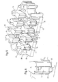
- recesses 54, 56 are provided in the region of the webs 44 and at the receptacles 26 in the region of the webs 44 are both on the actuating tappets 24 and at the receptacles 26 recesses 54, 56 are provided. These recesses 54, 56 prevent the breaklines 45, 47 from coming into contact with the actuating tappet 24 or the wall 48 of the receptacle 26 come.
- the actuating tappets 24 are located with the exception of the recesses 54, 56 on the wall 48 of the receptacles 26 at.
- each actuating plunger 24 is integrally a pin 60th formed.
- the pins 60 extend through associated openings in the connector 20 and fasten the connecting element 20 to the actuating tappets 24th
- each pin is under heat in a mushroom-shaped Head 62 formed, so that the connecting element 20 is not of the Actuator 24 can solve.
- the distance between the head 62 and the Connecting element 20 is chosen so that a tilting movement of the connecting element 20 with respect to the upper ends 22 of the actuating tappet 24 is possible.
Landscapes
- Manufacture Of Switches (AREA)
- Push-Button Switches (AREA)
- Tumbler Switches (AREA)
- Mechanisms For Operating Contacts (AREA)
Abstract
Description
- Figur 1 eine schematische Schnittansicht eines erfindungsgemäßen Kippschalters;
- Figur 2 eine schematische Schnittansicht einer Einheit aus einer Führungsplatte und zwei Betätigungsstößeln zur Verwendung in einem erfindungsgemäßen Verfahren zur Herstellung eines Kippschalters, nach der Fertigung der Einheit;
- Figur 3 die Einheit in Figur 2 nach dem Eindrücken der Betätigungsstößel in die Aufnahmen der Führungsplatte;
- Figur 4 die Einheit in Figur 2 in einer schematischen perspektivischen Darstellung;
- Figur 5 die Einheit in Figur 2 in einer weiteren schematischen perspektivischen Darstellung; und
- Figur 6 ein vergrößertes Detail aus Figur 5.
Claims (14)
- Kippschalter
mit einer Schaltwippe (14) mit wenigstens einem Arm (18),
einer Führungsplatte (28) mit wenigstens einer Aufnahme (26), in der wenigstens ein Betätigungsstößel (24) linear verschieblich gerührt ist, wobei der Arm (18) der Schaltwippe (14) eine Kraft auf den Betätigungsstößel (24) übertragen kann,
und einer Schaltereinheit (30, 32), auf die der Betätigungsstößel (24) einwirken kann, um einen elektrischen Kontakt zu schließen,
wobei die Führungsplatte (28) und der Betätigungsstößel (24) jeweils eine Bruchkante (45, 47) aufweisen, entlang der sie vor dem Zusammenbau des Kippschalters einstückig miteinander verbunden waren. - Kippschalter nach Anspruch 1, dadurch gekennzeichnet, daß vor einem Lösen des Betätigungsstößels (24) von der Führungsplatte (28) die Führungsplatte (28) und der Betätigungsstößel (24) durch wenigstens einen Steg (44) miteinander verbunden sind, der an einem unteren Ende (42) des Betätigungsstößels (24) und einem oberen Ende (46) einer Wand (48) der Aufnahme (26) angeordnet ist.
- Kippschalter nach Anspruch 2, dadurch gekennzeichnet, daß zwei Stege (44) am Betätigungsstößel (24) angeordnet sind.
- Kippschalter nach einem der vorhergehenden Ansprüche, dadurch gekennzeichnet, daß die Aufnahme (26) der Führungsplatte (28) im Bereich des Stegs (44) eine Aussparung (56) aufweist, die so ausgebildet ist, daß Reste des Stegs (44) nicht mit einer Wand (48) der Aufnahme (26) in Berührung kommen.
- Kippschalter nach einem der vorhergehenden Ansprüche, dadurch gekennzeichnet, daß der Betätigungsstößel (24) im Bereich des Stegs (44) eine Aussparung (54) aufweist, die so ausgebildet ist, daß Reste des Stegs (44) nicht mit dem Betätigungsstößel (24) in Berührung kommen.
- Kippschalter nach einem der vorhergehenden Ansprüche, dadurch gekennzeichnet, daß an einem oberen Ende (22) des Betätigungsstößels (24) ein Endanschlag (50) vorgesehen ist.
- Kippschalter nach einem der vorhergehenden Ansprüche, dadurch gekennzeichnet, daß an einem unteren Ende (42) des Betätigungsstößels (24) ein Rastelement vorgesehen ist.
- Kippschalter nach einem der vorhergehenden Ansprüche, dadurch gekennzeichnet, daß wenigstens zwei Betätigungsstößel (24) vorgesehen sind.
- Kippschalter nach Anspruch 8, dadurch gekennzeichnet, daß wenigstens ein Verbindungselement (20) vorgesehen ist, das die Betätigungsstößel (24) an deren oberen Enden (22) miteinander verbindet.
- Kippschalter nach Anspruch 9, dadurch gekennzeichnet, daß das obere Ende (22) jedes Betätigungsstößels (24) abgerundet ist und das Verbindungselement (20) auf den oberen Enden (22) aufliegt.
- Kippschalter nach einem der Ansprüche 9 und 10, dadurch gekennzeichnet, daß der Arm (18) der Schaltwippe (14) von der Mitte zwischen zwei Betätigungsstößeln (24) versetzt auf das Verbindungselement (20) einwirkt.
- Kippschalter nach einem der vorhergehenden Ansprüche, dadurch gekennzeichnet, daß die Schaltwippe (14) zwei Arme (18) hat.
- Verfahren zur Herstellung eines Kippschalters nach einem der vorhergehenden Ansprüche, dadurch gekennzeichnet daß die Führungsplatte (28) und der Betätigungsstößel (24) einstückig miteinander gefertigt werden und der Betätigungsstößel (24) durch eine Krafteinwirkung in die Aufnahme (26) der Führungsplatte (28) hinein gedrückt und hierbei von der Führungsplatte (28) gelöst wird.
- Verfahren zur Herstellung eines Kippschalters nach Anspruch 13, dadurch gekennzeichnet, daß die Führungsplatte (28) und der Betätigungsstößel (24) einstückig in einem Spritzgußverfahren hergestellt werden.
Applications Claiming Priority (2)
| Application Number | Priority Date | Filing Date | Title |
|---|---|---|---|
| DE10341101A DE10341101B4 (de) | 2003-09-05 | 2003-09-05 | Kippschalter |
| DE10341101 | 2003-09-05 |
Publications (3)
| Publication Number | Publication Date |
|---|---|
| EP1513175A2 true EP1513175A2 (de) | 2005-03-09 |
| EP1513175A3 EP1513175A3 (de) | 2007-04-11 |
| EP1513175B1 EP1513175B1 (de) | 2012-04-11 |
Family
ID=34129667
Family Applications (1)
| Application Number | Title | Priority Date | Filing Date |
|---|---|---|---|
| EP04018833A Expired - Lifetime EP1513175B1 (de) | 2003-09-05 | 2004-08-09 | Kippschalter |
Country Status (6)
| Country | Link |
|---|---|
| US (1) | US7071435B2 (de) |
| EP (1) | EP1513175B1 (de) |
| JP (1) | JP2005085762A (de) |
| CN (1) | CN1312713C (de) |
| AT (1) | ATE553492T1 (de) |
| DE (1) | DE10341101B4 (de) |
Cited By (2)
| Publication number | Priority date | Publication date | Assignee | Title |
|---|---|---|---|---|
| EP1988441A1 (de) * | 2007-05-03 | 2008-11-05 | Behr-Hella Thermocontrol GmbH | Bedieneinheit für eine Fahrzeugkomponente, insbesondere für eine Heizungs- oder Klimaanlage eines Fahrzeuges |
| EP2053623A3 (de) * | 2007-10-27 | 2010-06-16 | RAFI GmbH & Co. KG | Schaltvorrichtung |
Families Citing this family (11)
| Publication number | Priority date | Publication date | Assignee | Title |
|---|---|---|---|---|
| JP2005158492A (ja) * | 2003-11-26 | 2005-06-16 | Tokai Rika Co Ltd | パワーウインドスイッチ装置 |
| DE102004054617B3 (de) * | 2004-11-11 | 2006-05-11 | Zf Friedrichshafen Ag | Betätigungseinrichtung mit Tasten |
| JP4280250B2 (ja) * | 2005-06-17 | 2009-06-17 | オムロン株式会社 | スイッチ装置 |
| JP4528681B2 (ja) * | 2005-07-06 | 2010-08-18 | 株式会社東海理化電機製作所 | スイッチ部材及びそれを備えたパワーウィンド用スイッチ |
| US8989824B2 (en) * | 2007-01-05 | 2015-03-24 | Apple Inc. | Electronic devices with improved switch assembly constructions |
| JP5903253B2 (ja) * | 2011-11-24 | 2016-04-13 | 株式会社ヴァレオジャパン | スイッチ装置 |
| DE102014214218B4 (de) * | 2014-07-22 | 2017-06-14 | Behr-Hella Thermocontrol Gmbh | Bedieneinheit für ein elektrisches Gerät, insbesondere für eine Fahrzeugkomponente |
| JP6652875B2 (ja) * | 2016-04-06 | 2020-02-26 | アルプスアルパイン株式会社 | プッシュプルスイッチ装置 |
| US11485341B2 (en) | 2016-09-24 | 2022-11-01 | Bendix Commercial Vehicle Systems, Llc | Electronic park brake interface module, park brake controller and system |
| JP1727936S (ja) * | 2021-12-24 | 2022-10-21 | 自動車用スイッチ | |
| CN119314820B (zh) * | 2024-12-16 | 2025-07-22 | 乐清市华宝电子有限公司 | 拨动开关生产线 |
Citations (1)
| Publication number | Priority date | Publication date | Assignee | Title |
|---|---|---|---|---|
| DE3629723C2 (de) | 1985-08-30 | 1989-07-27 | Alps Electric Co., Ltd., Tokio/Tokyo, Jp |
Family Cites Families (13)
| Publication number | Priority date | Publication date | Assignee | Title |
|---|---|---|---|---|
| SE433675B (sv) * | 1981-04-09 | 1984-06-04 | Ericsson Telefon Ab L M | Forfarande for tillverkning av en tryckknappsats |
| US4877925A (en) * | 1987-10-23 | 1989-10-31 | Clarion Co., Ltd. | Multi-stage push button switch device |
| JP2517932Y2 (ja) * | 1988-05-31 | 1996-11-20 | 三菱電機株式会社 | スイツチ作動用押しボタン装置 |
| AU627396B2 (en) * | 1990-02-14 | 1992-08-20 | Yazaki Corporation | Two-stage rubber switch |
| US5130506A (en) * | 1990-02-28 | 1992-07-14 | Eaton Corporation | Low current switching apparatus having detent structure providing tactile feedback |
| US5332874A (en) * | 1993-01-14 | 1994-07-26 | Robertshaw Controls Company | Control device and method of making the same |
| US5584380A (en) * | 1993-09-02 | 1996-12-17 | Sumitomo Wiring Systems, Ltd. | Seesaw switch |
| US5508479A (en) * | 1994-11-17 | 1996-04-16 | Schooley; John L. | Elastomeric rocker switch assembly |
| US5703625A (en) * | 1995-01-06 | 1997-12-30 | Delco Electronics Corporation | Illuminated push button display |
| DE19600657C1 (de) | 1996-01-10 | 1997-04-24 | Kostal Leopold Gmbh & Co Kg | Mehrstufiger elektrischer Wippenschalter |
| US6175090B1 (en) * | 1999-09-02 | 2001-01-16 | Trw Inc. | Rocker switch |
| ITTO20010878A1 (it) * | 2001-09-14 | 2003-03-14 | Bitron Spa | Interruttore elettrico a lamina a doppio scatto. |
| ITTO20010877A1 (it) * | 2001-09-14 | 2003-03-14 | Bitron Spa | Dispositivo di azionamento di un interruttore elettrico a lamina a doppio scatto. |
-
2003
- 2003-09-05 DE DE10341101A patent/DE10341101B4/de not_active Expired - Fee Related
-
2004
- 2004-08-09 EP EP04018833A patent/EP1513175B1/de not_active Expired - Lifetime
- 2004-08-09 AT AT04018833T patent/ATE553492T1/de active
- 2004-08-31 US US10/931,175 patent/US7071435B2/en not_active Expired - Lifetime
- 2004-09-03 CN CNB2004100685791A patent/CN1312713C/zh not_active Expired - Fee Related
- 2004-09-06 JP JP2004257878A patent/JP2005085762A/ja active Pending
Patent Citations (1)
| Publication number | Priority date | Publication date | Assignee | Title |
|---|---|---|---|---|
| DE3629723C2 (de) | 1985-08-30 | 1989-07-27 | Alps Electric Co., Ltd., Tokio/Tokyo, Jp |
Cited By (2)
| Publication number | Priority date | Publication date | Assignee | Title |
|---|---|---|---|---|
| EP1988441A1 (de) * | 2007-05-03 | 2008-11-05 | Behr-Hella Thermocontrol GmbH | Bedieneinheit für eine Fahrzeugkomponente, insbesondere für eine Heizungs- oder Klimaanlage eines Fahrzeuges |
| EP2053623A3 (de) * | 2007-10-27 | 2010-06-16 | RAFI GmbH & Co. KG | Schaltvorrichtung |
Also Published As
| Publication number | Publication date |
|---|---|
| DE10341101B4 (de) | 2006-10-12 |
| ATE553492T1 (de) | 2012-04-15 |
| EP1513175B1 (de) | 2012-04-11 |
| CN1312713C (zh) | 2007-04-25 |
| US7071435B2 (en) | 2006-07-04 |
| DE10341101A1 (de) | 2005-04-21 |
| JP2005085762A (ja) | 2005-03-31 |
| CN1591728A (zh) | 2005-03-09 |
| EP1513175A3 (de) | 2007-04-11 |
| US20050051413A1 (en) | 2005-03-10 |
Similar Documents
| Publication | Publication Date | Title |
|---|---|---|
| DE3019886C2 (de) | Schiebeschalter | |
| DE19537296C2 (de) | Wippenschaltvorrichtung für zweistufigen Betätigungshub | |
| EP0100936B1 (de) | Tastenschalter | |
| DE69106745T2 (de) | Schalter mit Berührungseffekt und diesen Schalter verwendende Tastatur. | |
| EP1513175B1 (de) | Kippschalter | |
| DE3424771A1 (de) | Tastenfeld | |
| DE19517538A1 (de) | Mehrweg-Kippschalter | |
| DE60101520T2 (de) | Tastschalter mit Tastenkopf welcher auf- und abbewegbar ist und Verfahren zu seiner Herstellung | |
| EP0163874A2 (de) | Tastschalter | |
| DE2337904A1 (de) | Eingabe-taste | |
| DE2301853A1 (de) | Tastschalter | |
| DE3441614C2 (de) | ||
| DE2537284A1 (de) | Prellfreier elektrischer schalter | |
| DE102006007090B4 (de) | Schaltervorrichtung | |
| EP0252449B1 (de) | Drucktastenschalter, insbesondere Tastschalter | |
| DE102021110000A1 (de) | Drucktastenbaugruppe | |
| EP0110094A1 (de) | Taste zum Schliessen elektrischer Kontakte | |
| DE2148804C2 (de) | Drucktastenschalter, insbesondere mehrfach-drucktastenschalter | |
| EP2056318A1 (de) | Schalter, insbesondere Fensterheberschalter | |
| DE19836793C2 (de) | Bedienelement zum selektiven Herstellen elektrischer Kontakte | |
| DE102013223843A1 (de) | Tastenknopf, Tastenschalter, Tastenrahmen und Leiterplatte für eine Dateneingabevorrichtung, Dateneingabevorrichtung und Verfahren zur Reduzierung eines Schaltweges eines Tastenschalters einer Dateneingabevorrichtung | |
| EP1482527B1 (de) | Tastenblock | |
| DE10349592B4 (de) | Tastenblock zum Einsetzen in eine Blende und Montageanordnung eines Tastenblocks an einer Blende | |
| DE4112646C2 (de) | Druckknopfschalter, insbesondere für ein Tastenfeld einer Datenverarbeitungsanlage, z. B. eines Rechners | |
| DE2829891A1 (de) | Drucktastenschalter |
Legal Events
| Date | Code | Title | Description |
|---|---|---|---|
| PUAI | Public reference made under article 153(3) epc to a published international application that has entered the european phase |
Free format text: ORIGINAL CODE: 0009012 |
|
| AK | Designated contracting states |
Kind code of ref document: A2 Designated state(s): AT BE BG CH CY CZ DE DK EE ES FI FR GB GR HU IE IT LI LU MC NL PL PT RO SE SI SK TR |
|
| AX | Request for extension of the european patent |
Extension state: AL HR LT LV MK |
|
| PUAL | Search report despatched |
Free format text: ORIGINAL CODE: 0009013 |
|
| AK | Designated contracting states |
Kind code of ref document: A3 Designated state(s): AT BE BG CH CY CZ DE DK EE ES FI FR GB GR HU IE IT LI LU MC NL PL PT RO SE SI SK TR |
|
| AX | Request for extension of the european patent |
Extension state: AL HR LT LV MK |
|
| 17P | Request for examination filed |
Effective date: 20070913 |
|
| AKX | Designation fees paid |
Designated state(s): AT BE BG CH CY CZ DE DK EE ES FI FR GB GR HU IE IT LI LU MC NL PL PT RO SE SI SK TR |
|
| 17Q | First examination report despatched |
Effective date: 20100412 |
|
| GRAP | Despatch of communication of intention to grant a patent |
Free format text: ORIGINAL CODE: EPIDOSNIGR1 |
|
| RTI1 | Title (correction) |
Free format text: TUMBLER SWITCH |
|
| GRAS | Grant fee paid |
Free format text: ORIGINAL CODE: EPIDOSNIGR3 |
|
| GRAA | (expected) grant |
Free format text: ORIGINAL CODE: 0009210 |
|
| RAP1 | Party data changed (applicant data changed or rights of an application transferred) |
Owner name: TRW AUTOMOTIVE ELECTRONICS & COMPONENTS GMBH |
|
| AK | Designated contracting states |
Kind code of ref document: B1 Designated state(s): AT BE BG CH CY CZ DE DK EE ES FI FR GB GR HU IE IT LI LU MC NL PL PT RO SE SI SK TR |
|
| REG | Reference to a national code |
Ref country code: GB Ref legal event code: FG4D Free format text: NOT ENGLISH |
|
| REG | Reference to a national code |
Ref country code: CH Ref legal event code: EP |
|
| REG | Reference to a national code |
Ref country code: AT Ref legal event code: REF Ref document number: 553492 Country of ref document: AT Kind code of ref document: T Effective date: 20120415 |
|
| REG | Reference to a national code |
Ref country code: IE Ref legal event code: FG4D Free format text: LANGUAGE OF EP DOCUMENT: GERMAN |
|
| REG | Reference to a national code |
Ref country code: DE Ref legal event code: R096 Ref document number: 502004013424 Country of ref document: DE Effective date: 20120606 |
|
| REG | Reference to a national code |
Ref country code: NL Ref legal event code: VDEP Effective date: 20120411 |
|
| PG25 | Lapsed in a contracting state [announced via postgrant information from national office to epo] |
Ref country code: SE Free format text: LAPSE BECAUSE OF FAILURE TO SUBMIT A TRANSLATION OF THE DESCRIPTION OR TO PAY THE FEE WITHIN THE PRESCRIBED TIME-LIMIT Effective date: 20120411 Ref country code: CY Free format text: LAPSE BECAUSE OF FAILURE TO SUBMIT A TRANSLATION OF THE DESCRIPTION OR TO PAY THE FEE WITHIN THE PRESCRIBED TIME-LIMIT Effective date: 20120411 Ref country code: PL Free format text: LAPSE BECAUSE OF FAILURE TO SUBMIT A TRANSLATION OF THE DESCRIPTION OR TO PAY THE FEE WITHIN THE PRESCRIBED TIME-LIMIT Effective date: 20120411 Ref country code: FI Free format text: LAPSE BECAUSE OF FAILURE TO SUBMIT A TRANSLATION OF THE DESCRIPTION OR TO PAY THE FEE WITHIN THE PRESCRIBED TIME-LIMIT Effective date: 20120411 |
|
| PGFP | Annual fee paid to national office [announced via postgrant information from national office to epo] |
Ref country code: GB Payment date: 20120828 Year of fee payment: 9 |
|
| PG25 | Lapsed in a contracting state [announced via postgrant information from national office to epo] |
Ref country code: SI Free format text: LAPSE BECAUSE OF FAILURE TO SUBMIT A TRANSLATION OF THE DESCRIPTION OR TO PAY THE FEE WITHIN THE PRESCRIBED TIME-LIMIT Effective date: 20120411 Ref country code: PT Free format text: LAPSE BECAUSE OF FAILURE TO SUBMIT A TRANSLATION OF THE DESCRIPTION OR TO PAY THE FEE WITHIN THE PRESCRIBED TIME-LIMIT Effective date: 20120813 Ref country code: GR Free format text: LAPSE BECAUSE OF FAILURE TO SUBMIT A TRANSLATION OF THE DESCRIPTION OR TO PAY THE FEE WITHIN THE PRESCRIBED TIME-LIMIT Effective date: 20120712 |
|
| PGFP | Annual fee paid to national office [announced via postgrant information from national office to epo] |
Ref country code: IT Payment date: 20120822 Year of fee payment: 9 Ref country code: FR Payment date: 20120830 Year of fee payment: 9 Ref country code: ES Payment date: 20120827 Year of fee payment: 9 |
|
| PG25 | Lapsed in a contracting state [announced via postgrant information from national office to epo] |
Ref country code: SK Free format text: LAPSE BECAUSE OF FAILURE TO SUBMIT A TRANSLATION OF THE DESCRIPTION OR TO PAY THE FEE WITHIN THE PRESCRIBED TIME-LIMIT Effective date: 20120411 Ref country code: RO Free format text: LAPSE BECAUSE OF FAILURE TO SUBMIT A TRANSLATION OF THE DESCRIPTION OR TO PAY THE FEE WITHIN THE PRESCRIBED TIME-LIMIT Effective date: 20120411 Ref country code: EE Free format text: LAPSE BECAUSE OF FAILURE TO SUBMIT A TRANSLATION OF THE DESCRIPTION OR TO PAY THE FEE WITHIN THE PRESCRIBED TIME-LIMIT Effective date: 20120411 Ref country code: CZ Free format text: LAPSE BECAUSE OF FAILURE TO SUBMIT A TRANSLATION OF THE DESCRIPTION OR TO PAY THE FEE WITHIN THE PRESCRIBED TIME-LIMIT Effective date: 20120411 Ref country code: NL Free format text: LAPSE BECAUSE OF FAILURE TO SUBMIT A TRANSLATION OF THE DESCRIPTION OR TO PAY THE FEE WITHIN THE PRESCRIBED TIME-LIMIT Effective date: 20120411 Ref country code: DK Free format text: LAPSE BECAUSE OF FAILURE TO SUBMIT A TRANSLATION OF THE DESCRIPTION OR TO PAY THE FEE WITHIN THE PRESCRIBED TIME-LIMIT Effective date: 20120411 |
|
| PLBE | No opposition filed within time limit |
Free format text: ORIGINAL CODE: 0009261 |
|
| STAA | Information on the status of an ep patent application or granted ep patent |
Free format text: STATUS: NO OPPOSITION FILED WITHIN TIME LIMIT |
|
| BERE | Be: lapsed |
Owner name: TRW AUTOMOTIVE ELECTRONICS & COMPONENTS G.M.B.H. Effective date: 20120831 |
|
| 26N | No opposition filed |
Effective date: 20130114 |
|
| REG | Reference to a national code |
Ref country code: CH Ref legal event code: PL |
|
| PG25 | Lapsed in a contracting state [announced via postgrant information from national office to epo] |
Ref country code: MC Free format text: LAPSE BECAUSE OF NON-PAYMENT OF DUE FEES Effective date: 20120831 |
|
| PG25 | Lapsed in a contracting state [announced via postgrant information from national office to epo] |
Ref country code: CH Free format text: LAPSE BECAUSE OF NON-PAYMENT OF DUE FEES Effective date: 20120831 Ref country code: LI Free format text: LAPSE BECAUSE OF NON-PAYMENT OF DUE FEES Effective date: 20120831 Ref country code: ES Free format text: LAPSE BECAUSE OF FAILURE TO SUBMIT A TRANSLATION OF THE DESCRIPTION OR TO PAY THE FEE WITHIN THE PRESCRIBED TIME-LIMIT Effective date: 20120722 |
|
| REG | Reference to a national code |
Ref country code: DE Ref legal event code: R097 Ref document number: 502004013424 Country of ref document: DE Effective date: 20130114 |
|
| REG | Reference to a national code |
Ref country code: IE Ref legal event code: MM4A |
|
| PG25 | Lapsed in a contracting state [announced via postgrant information from national office to epo] |
Ref country code: BE Free format text: LAPSE BECAUSE OF NON-PAYMENT OF DUE FEES Effective date: 20120831 |
|
| PG25 | Lapsed in a contracting state [announced via postgrant information from national office to epo] |
Ref country code: IE Free format text: LAPSE BECAUSE OF NON-PAYMENT OF DUE FEES Effective date: 20120809 Ref country code: BG Free format text: LAPSE BECAUSE OF FAILURE TO SUBMIT A TRANSLATION OF THE DESCRIPTION OR TO PAY THE FEE WITHIN THE PRESCRIBED TIME-LIMIT Effective date: 20120711 |
|
| REG | Reference to a national code |
Ref country code: AT Ref legal event code: MM01 Ref document number: 553492 Country of ref document: AT Kind code of ref document: T Effective date: 20120831 |
|
| PG25 | Lapsed in a contracting state [announced via postgrant information from national office to epo] |
Ref country code: AT Free format text: LAPSE BECAUSE OF NON-PAYMENT OF DUE FEES Effective date: 20120831 |
|
| GBPC | Gb: european patent ceased through non-payment of renewal fee |
Effective date: 20130809 |
|
| PG25 | Lapsed in a contracting state [announced via postgrant information from national office to epo] |
Ref country code: TR Free format text: LAPSE BECAUSE OF FAILURE TO SUBMIT A TRANSLATION OF THE DESCRIPTION OR TO PAY THE FEE WITHIN THE PRESCRIBED TIME-LIMIT Effective date: 20120411 |
|
| REG | Reference to a national code |
Ref country code: FR Ref legal event code: ST Effective date: 20140430 |
|
| PG25 | Lapsed in a contracting state [announced via postgrant information from national office to epo] |
Ref country code: LU Free format text: LAPSE BECAUSE OF NON-PAYMENT OF DUE FEES Effective date: 20120809 Ref country code: IT Free format text: LAPSE BECAUSE OF NON-PAYMENT OF DUE FEES Effective date: 20130809 |
|
| PG25 | Lapsed in a contracting state [announced via postgrant information from national office to epo] |
Ref country code: HU Free format text: LAPSE BECAUSE OF FAILURE TO SUBMIT A TRANSLATION OF THE DESCRIPTION OR TO PAY THE FEE WITHIN THE PRESCRIBED TIME-LIMIT Effective date: 20040809 Ref country code: GB Free format text: LAPSE BECAUSE OF NON-PAYMENT OF DUE FEES Effective date: 20130809 |
|
| PG25 | Lapsed in a contracting state [announced via postgrant information from national office to epo] |
Ref country code: FR Free format text: LAPSE BECAUSE OF NON-PAYMENT OF DUE FEES Effective date: 20130902 |
|
| REG | Reference to a national code |
Ref country code: DE Ref legal event code: R081 Ref document number: 502004013424 Country of ref document: DE Owner name: BCS AUTOMOTIVE INTERFACE SOLUTIONS GMBH, DE Free format text: FORMER OWNER: TRW AUTOMOTIVE ELECTRONICS & COMPONENTS GMBH, 78315 RADOLFZELL, DE |
|
| PGFP | Annual fee paid to national office [announced via postgrant information from national office to epo] |
Ref country code: DE Payment date: 20200827 Year of fee payment: 17 |
|
| REG | Reference to a national code |
Ref country code: DE Ref legal event code: R119 Ref document number: 502004013424 Country of ref document: DE |
|
| PG25 | Lapsed in a contracting state [announced via postgrant information from national office to epo] |
Ref country code: DE Free format text: LAPSE BECAUSE OF NON-PAYMENT OF DUE FEES Effective date: 20220301 |
|
| PGFP | Annual fee paid to national office [announced via postgrant information from national office to epo] |
Ref country code: ES Payment date: 20221001 Year of fee payment: 9 |