EP1512987A1 - Abstandsmessverfahren und -einrichtung - Google Patents
Abstandsmessverfahren und -einrichtung Download PDFInfo
- Publication number
- EP1512987A1 EP1512987A1 EP03736015A EP03736015A EP1512987A1 EP 1512987 A1 EP1512987 A1 EP 1512987A1 EP 03736015 A EP03736015 A EP 03736015A EP 03736015 A EP03736015 A EP 03736015A EP 1512987 A1 EP1512987 A1 EP 1512987A1
- Authority
- EP
- European Patent Office
- Prior art keywords
- distance
- measured
- radar image
- waves
- standing
- Prior art date
- Legal status (The legal status is an assumption and is not a legal conclusion. Google has not performed a legal analysis and makes no representation as to the accuracy of the status listed.)
- Withdrawn
Links
Images


Classifications
-
- G—PHYSICS
- G01—MEASURING; TESTING
- G01S—RADIO DIRECTION-FINDING; RADIO NAVIGATION; DETERMINING DISTANCE OR VELOCITY BY USE OF RADIO WAVES; LOCATING OR PRESENCE-DETECTING BY USE OF THE REFLECTION OR RERADIATION OF RADIO WAVES; ANALOGOUS ARRANGEMENTS USING OTHER WAVES
- G01S13/00—Systems using the reflection or reradiation of radio waves, e.g. radar systems; Analogous systems using reflection or reradiation of waves whose nature or wavelength is irrelevant or unspecified
- G01S13/02—Systems using reflection of radio waves, e.g. primary radar systems; Analogous systems
- G01S13/06—Systems determining position data of a target
- G01S13/08—Systems for measuring distance only
- G01S13/32—Systems for measuring distance only using transmission of continuous waves, whether amplitude-, frequency-, or phase-modulated, or unmodulated
- G01S13/36—Systems for measuring distance only using transmission of continuous waves, whether amplitude-, frequency-, or phase-modulated, or unmodulated with phase comparison between the received signal and the contemporaneously transmitted signal
- G01S13/40—Systems for measuring distance only using transmission of continuous waves, whether amplitude-, frequency-, or phase-modulated, or unmodulated with phase comparison between the received signal and the contemporaneously transmitted signal wherein the frequency of transmitted signal is adjusted to give a predetermined phase relationship
-
- G—PHYSICS
- G01—MEASURING; TESTING
- G01S—RADIO DIRECTION-FINDING; RADIO NAVIGATION; DETERMINING DISTANCE OR VELOCITY BY USE OF RADIO WAVES; LOCATING OR PRESENCE-DETECTING BY USE OF THE REFLECTION OR RERADIATION OF RADIO WAVES; ANALOGOUS ARRANGEMENTS USING OTHER WAVES
- G01S13/00—Systems using the reflection or reradiation of radio waves, e.g. radar systems; Analogous systems using reflection or reradiation of waves whose nature or wavelength is irrelevant or unspecified
- G01S13/88—Radar or analogous systems specially adapted for specific applications
- G01S13/887—Radar or analogous systems specially adapted for specific applications for detection of concealed objects, e.g. contraband or weapons
-
- G—PHYSICS
- G01—MEASURING; TESTING
- G01S—RADIO DIRECTION-FINDING; RADIO NAVIGATION; DETERMINING DISTANCE OR VELOCITY BY USE OF RADIO WAVES; LOCATING OR PRESENCE-DETECTING BY USE OF THE REFLECTION OR RERADIATION OF RADIO WAVES; ANALOGOUS ARRANGEMENTS USING OTHER WAVES
- G01S13/00—Systems using the reflection or reradiation of radio waves, e.g. radar systems; Analogous systems using reflection or reradiation of waves whose nature or wavelength is irrelevant or unspecified
- G01S13/02—Systems using reflection of radio waves, e.g. primary radar systems; Analogous systems
- G01S13/06—Systems determining position data of a target
- G01S13/08—Systems for measuring distance only
- G01S13/32—Systems for measuring distance only using transmission of continuous waves, whether amplitude-, frequency-, or phase-modulated, or unmodulated
Definitions
- the present invention relates to a distance measuring method capable of measuring, in a non-contacting manner by the use of standing wave, a distance to an object to be measured.
- Hitherto distance measurement is one of basic physical quantities measurements, and many methods have heretofore been employed therefor.
- Distance is equal to "length” in a physical dimension and they are often overlapped in concept.
- the measurement is often considered to be a "distance"
- the measurement is often considered to be a "length”
- a basic instrument for measurement of length is a rule, which is graduated according to a predetermined reference.
- Japanese Unexamined patent Publication JP-A-3-144306 (1991) discloses a prior art related to a length-measuring instrument in which a slit is formed in a waveguide so as to extend in the axial direction, electromagnetic standing waves are generated in the waveguide, and a slider which inserts a plurality of probes from the outside into the inside of the waveguide through the slit is moved in the axial direction to find the position of the slider based on the amplitude of the standing waves detected by the probes.
- the present applicant further discloses in Japanese Unexamined Patent Publication JP-A-11-230734 (1999) a prior art related to a linear encoder in which standing waves are formed in a linear conductor passage with the use of frequency-modulated waves whose frequency periodically changes, and the layer position of the conductor passage is measured based on a correlation between the modulated signals and the envelope of standing waves in the conductor passage.
- electromagnetic standing waves can be formed in a propagation medium such as space that exists relative to an object to be measured, have developed the idea of using the standing waves applied to the conductor passage in Japanese Unexamined Patent Publication JP-A-11-230734 (1999), and have proposed in Japanese Patent Application No. 2001-237280 a technology capable of measuring the distance in a non-contacting manner.
- the waveguide or the conductor passage corresponding to the rule is installed between a position that serves as a reference of measurement and the object to be measured, and must be brought into mechanical contact with the object to be measured.
- the technology proposed in Japanese Patent Application No. 2001-237280 uses standing waves which are formed in electromagnetic waves or the like whose propagation medium is, for example, space, and accordingly it is made possible to measure a distance to an object in a non-contacting manner. Therefore, this technology can be utilized as a radar which is mounted on a mobile body such as an automobile.
- the frequency of electromagnetic waves or the like for generating the standing waves is varied to find a detection signal function that represents a relationship between the amplitude of the detected standing waves and the frequency, and a frequency at which the detection signal function assumes an extreme value is related to a distance to the object to be measured.
- a detection signal function that represents a relationship between the amplitude of the detected standing waves and the frequency
- a frequency at which the detection signal function assumes an extreme value is related to a distance to the object to be measured.
- changes in the detection signal function decrease near the extreme value, and it becomes difficult to correctly specify the position of the extreme value with the result that enhancement of resolution has its limitation.
- noise components are overlapped on the detection signal function, and the error range of the position of the extreme value which is specified based on the amplitude data only tends to increase.
- the phase includes a phase shift quantity due to the reflection by the object to be measured, which makes it, usually, difficult to correctly find a phase shift quantity and hence it is necessary to be considered as being an unknown quantity.
- changes in phase constitute a periodic function of a short period as compared to changes in amplitude, and there exist a plurality of phases having a predetermined relationship to the phase shift quantity even near the extreme value of amplitude. Therefore, it is difficult to specify the extreme value of amplitude though the phase shift quantity can be correctly found.
- the invention is a distance measuring method for measuring a distance from a reference position to an object to be measured, comprising the steps of:
- the invention is characterized in that an object to be measured for which a distance is measured and an object to be measured that serves as a reference for measuring the distance are simultaneously measured.
- the invention is a distance measuring apparatus for measuring a distance from a reference position to an object to be measured, comprising:
- the invention is characterized in that the radar image calculating means calculates the plurality of radar image functions based on a Fourier transform processing; and the distance judging means judges, as the distance in which the above predetermined conditions are satisfied, a distance in which a phase difference between at least two radar images functions is 0 or is a radian value of an even number of times of the pi ⁇ , and the amplitude of at least any one of the radar image functions is an extreme value.
- the radar image calculating means calculates the plurality of radar image functions by subjecting the signals corresponding to the standing waves to the Fourier transform processing with a variable common width for the plurality of different center frequencies by using a predetermined window function.
- the traveling wave generating means includes:
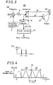
- Fig. 1 schematically illustrates a constitution for measuring a distance according to an embodiment of the invention.
- the distance measuring apparatus 1 is capable of varying the oscillation frequency depending upon a voltage applied from an external unit, and a Voltage Controlled Oscillator (abbreviated as VCO) 2 generates electric signals of a high frequency, which are fed to an antenna 4 through a transmission system 3 which effects the power amplification and impedance matching.
- VCO Voltage Controlled Oscillator
- the antenna 4 converts electric signals of a high frequency that are fed into electromagnetic waves which are transmitted into the surrounding space.
- a target 5 which is an object to be measured exists at a distance d from the antenna 4 in a direction in which the electromagnetic waves travel being transmitted from the antenna 4, standing waves generate due to the interference between the traveling waves incident on the target 5 and the waves reflected by the target 5.
- the antenna 4 receives the electric signals corresponding to the standing waves, and the electric power of the standing waves is detected as a square power of the received input voltage by a power detector 6 as standing wave detecting means.
- the oscillation frequency of the voltage controlled oscillator 2 is varied by a control voltage given by a frequency controller 7.
- the frequency of high-frequency signals generated from the voltage controlled oscillator 2 can be directly used, multiplied into a frequency of a plurality of times as high, or can be heterodyne-converted.
- the voltage controlled oscillator 2, antenna 4 and frequency controller 7 serves as traveling wave generating means.
- the power of the standing waves detected by the power detector 6 is converted into a radar image function by radar image calculating means 10.
- the radar image calculating means 10 includes a plurality of or, for example, two Fourier transform means 11 and 12.
- a first Fourier transform means 11 is related to a first center frequency f1 between the center frequencies f1 and f2, and converts a power function p1(f, 0) into a radar image function P1(x).
- a second Fourier transform means 12 is related to a second center frequency f2, and converts a power function p2(f, 0) into a radar image function P2(x).
- the radar image calculating means 10 can be operated as a plurality of Fourier operation means 11, 12 by a program processing using a general-purpose central processing unit (CPU). It can be further operated at a high speed by using a digital signal processor (DSP). The operation processing can be effected at a further high speed by operating a plurality of digital signal processors in parallel. The speed can be further increased by forming a circuit dedicated to the Fourier operation processing.
- CPU general-purpose central processing unit
- DSP digital signal processor
- Fig. 2 illustrates conditions for specifying the position of the target 15 according to the embodiment.
- Fig. 2(a) illustrates changes in the amplitude of two radar image functions P1(x) and P2(x) in a standardized manner.
- Fig. 2(b) illustrates changes in the phases ⁇ 1 and ⁇ 2 of two radar image functions P1 and P2 using a dot-dash chain line and a two-dot chain line, a solid line representing a change in the phase difference ⁇ .
- Figs. 3 to 7 illustrates a principle for specifying a distance to the target 15 which is the object to be measured according to the embodiment of the invention.
- the basic idea of this principle has been disclosed in Japanese Patent application No. 2001-237280.
- FIG. 3 illustrates an electric constitution of the distance measuring apparatus 20 that serves as a basis of the invention, and (b) illustrates a change in the amplitude of the radar image function.
- the portions corresponding to those of the embodiment of Fig. 1 are denoted by the same reference numerals, but their description is not repeated.
- Fig. 3 illustrates a case of simultaneously measuring the distances d1 to dn to a plurality of targets 21 to 2n instead of using one target 5 as the object to be measured of Fig. 1.
- the electromagnetic wave signals transmitted from the antenna 4 become traveling waves traveling the space toward the targets 21 to 2n.
- the traveling waves are reflected by the targets 21 to 2n.
- the reflected waves that return back to the antenna 4 interfere with the traveling waves to form standing waves.
- Due to the presence of the standing waves the amplitude and electric power of signals observed at points on the x-axes which are imaginary straight lines passing through the plurality of targets 21 to 2n from the antenna 4, undergo a periodic change relative to the frequency f of the traveling waves from the signal source.
- the distance measuring apparatus 20 measures the distance d to the object to be measured with the power-feeding portion of the antenna 4 as a point of observation.
- the standing waves are generated by the additional synthesis of the traveling waves VT and the reflected waves VRk, and from the formulas (1) and (2), a power function p(f, x) which is a square power thereof is found from the following formula (3),
- p(f, 0) is regarded to be time waveform and is put to the Fourier transform.
- the Fourier-transformed P(x) of p(f, 0) can be expressed by the following formula (5),
- the radar image function P(x) can be found from the following formula (6), where w(f) is a window function, and there can be favorably used the Blackman-Harris window expressed by the following formula (7),
- the radar image function P(x) can be calculated as given by the following formula (9),
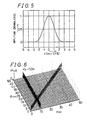
- Fig. 5 shows the shape of a normalized function of W(x) used for the formula (9).
- Fig. 6 illustrates the calculated results of absolute values
- the center frequency f0 is 7.75 GHz and fB is 500 MHz.
- ⁇ k is set to be 0.1 and ⁇ k to be ⁇ .
- p(f, 0) there is used the one obtained by removing the DC component from the formula (3).
- the results of calculation include secondary or higher terms of ⁇ k. It is also possible to simultaneously measure the distances to the plurality of targets 21, 22. In case where one distance d2 is measured in advance or later by other method, then, the other distance d1 can be corrected based on the measured value.
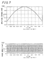
- Fig. 7(a) illustrates a change in the normalized amplitude
- Fig. 7(b) illustrates a change in the phase ⁇ P(x) which is represented by radian vcalue.
- f0 is 7.75 GHz
- the distance d can be found by searching a point where the amplitude
- the phase shift quantity ⁇ is unknown and is displayed in Fig. 7(b) being folded in a range of ⁇ . Therefore, even if a value ⁇ is found within a range of - ⁇ ⁇ ⁇ + ⁇ , a plurality of displacements ⁇ x are corresponded thereto, and the distance d cannot be judged.
- of the radar image function changes like a mild mountain, and it is difficult to accurately specify a maximum position and there is a limit in conducting the measurement with high resolution. Besides, in the practical measurement, random noise is superposed making it further difficult to judge a maximum position.
- the phase ⁇ P(x) sharply changes and is corresponded to a plurality of displacements ⁇ x near a maximum value of the amplitude
- a plurality of different center frequencies f1, f2 are set as illustrated in Fig. 1(b), two radar image functions P1(x) and P2(x) are obtained by using two Fourier transform means 11 and 12, and a distance d is found from the amplitudes thereof and from the phase difference as illustrated in Fig. 2.
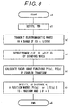
- Fig. 8 schematically illustrates a procedure for specifying the distance d by the distance measuring apparatus 1 of this embodiment.
- the procedure starts with step s0.
- the frequency controller 7 sets the center frequency f0 and the variable width fB0 of the voltage controlled oscillator 2 so as to oscillate it.
- traveling waves are transmitted from the antenna 4, the frequency f of the signal source of which varying over a range of f0 ⁇ 1/2 x fB0.
- the frequency of the signal source must remain stable for a period of time long enough for the reflected waves returning back to the antenna 4 to interfere with the traveling waves to form standing waves.
- the distance d is short as compared to the velocity c of light, and the required time is short.
- the frequency controller 7 controls the oscillation frequency of the voltage controlled oscillator 2 in a digital manner, the frequency of the signal source changes stepwise sufficiently satisfying the time conditions for generating the standing waves.
- the power detector 6 detects the power p(f, 0) corresponding to the amplitude of the standing waves input to the antenna 4.
- the reflection coefficient ⁇ and the phase shift quantity ⁇ can be regarded to be constant.
- the ranges f1 ⁇ 1/2 x fB1 and f2 ⁇ 1/2 x fB2 are picked up out of the detected power p(f, 0) as illustrated in Fig. 1(b), and are transformed into radar image functions P1(x) and P2(x) through the Fourier transform processing such as FFT (Fast Fourier Transfer) using the Fourier transform means 11 and 12.
- FFT Fast Fourier Transfer
- Fig. 2(a) illustrates normalized amplitudes of radar image functions P1(x) and P2(x) represented by the formulas (14) and (15).
- the amplitudes of the two radar image functions are the same. Depending upon the shape of the function corresponding to the standing waves, it can be considered that the amplitude assumes a minimum value at a position where the target exists.
- Figs. 2(a) illustrates normalized amplitudes of radar image functions P1(x) and P2(x) represented by the formulas (14) and (15).
- the amplitudes of the two radar image functions are the same. Depending upon the shape of the function corresponding to the standing waves, it can be considered that the amplitude assumes a minimum value at a position where the target exists.
- the distance d to the target 5 is specified, the target 5 being located at a position where the amplitude
- the procedure ends at step s6.
- power signals of the two center frequencies f1 and f2 are picked up from common power signals.
- the power signals can also be detected by dividing the timing for detecting the standing waves by changing the frequency f of the signal source for each of the center frequencies f1 and f2.
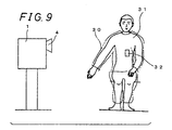
- Fig. 9 schematically illustrates a state of measuring, in a non-contacting manner, the distance to the surface of a human body 31 wearing clothes 30 by using the distance measuring apparatus 1 of this embodiment.
- the clothes 30 that is electrically insulating permits electromagnetic waves to pass through so as to be reflected by the surface of the human body 31 to thereby form standing waves.
- the distance is highly precisely measured based on the standing waves; i.e., the distance is measured by correctly reflecting a distance between the clothes 30 and the surface of the skin of the human body 31.
- the size can be measured in case where the distance to the human body 31 is measured at a plurality of points. For example, even if it is attempted to measure the distance to the human body 31 wearing clothes 30 in a non-contacting manner relying upon the optical measurement, the surface shape only of the clothes 30 can be measured.
- the frequency of the signal source may be increased. It is considered the size of the region that can be measured is of the order of wavelength of electromagnetic waves.
- the wavelength becomes 1 cm at 30 GHz. Therefore, a frequency of about 30 GHz to about 60 GHz may be used. The distance is short and can, hence, be measured even with a very small output.
- the measurement illustrated in Fig. 9 is capable of detecting even an electrically conducting material 32 concealed under the clothes 30. In case where the electromagnetic waves for detection are scanned, the image of the material 32 can be formed.
- the distance measuring apparatus 1 is capable of simultaneously measuring even a plurality of targets as illustrated in Fig. 3.
- the distances based on the phase differences can be judged with high resolution for a plurality of peaks of amplitude of the radar image function as illustrated in Fig. 3(b).
- the distance may be measured in advance by any other method using a target as a reference or may be measured later thereby to measure a distance to a target that is the object to be measured relying upon the distance to the target that serves as a reference with high precision.
- the distance measuring apparatus 1 of this embodiment can further be used as a radar device proposed in Japanese Patent Application No. 2001-237280. Further, car-mounted sensors and road-side sensors that are for measuring the distances can be realized with high precision for realizing an intelligent traffic system (ITS).
- ITS intelligent traffic system
- the apparatus can be further applied to a level gauge, a berthing instrument for ships, an altimeter of aircraft and landslide measuring instrument, that effect measurement in absolute values with high resolution.
- the idea of the invention can be applied not only to electromagnetic waves using space as a propagation medium but also to sound waves using, for example, the air as a propagation medium.
- the speed of sound varies depending upon the temperature.
- the distance to the object to be measured can be correctly measured even if the speed of sound is unknown.
- the liquid or the solid can be utilized as a propagation medium.
- the standing waves generated on the surface waves can be utilized for measuring the distance.
- standing waves are generated not by using the wave motion of the electromagnetic waves but by using the wave motion which is a change in the amplitude, and are used for measuring the distance.
- traveling waves that travel from the reference position to the object to be measured are generated in a propagation medium existing surrounding the reference position and the object to be measured while varying the frequency, and the generated traveling waves are caused to interfere with the waves reflected by the object to be measured to thereby generate standing waves. Therefore, a measuring instrument that corresponds to a rule needs not be brought into contact with the object to be measured, and the distance can be measured even to the object that is freely moving.
- the standing waves are detected in the standing wave detecting step, and a plurality of radar image functions are calculated from the detected standing waves based on a plurality of different center frequencies in which radar image functions a variable is a distance from the reference position to a point on an imaginary linear axis passing through the object to be measured in the radar image calculating step.
- a difference among the center frequencies is small as compared to the absolute values of the center frequencies, the reflection by the object to be measured equally affects the calculated radar image functions.
- the distance judging step as the distance from the reference position to the object to be measured, a distance in which predetermined conditions are satisfied by phase differences among the plurality of radar image functions calculated in the radar image calculating step and by the amplitude of any radar image function, is judged.
- phase difference due to the reflection by the object to be measured.
- period of change in the phase difference is larger than a period of change in the phase of the radar image functions. Therefore, the distance in which the predetermined condition are satisfied by the amplitude of the radar image functions can be specified from a phase difference with high resolution.
- an object to be measured for which a distance is measured and an object to be measured that serves as a reference for measuring the distance are simultaneously measured, and it is possible to determine a relative difference in the distances to the objects with high resolution.
- the distance to the object that serves as a reference for measuring the distance is directly measured in advance or later and, based on this distance, the absolute distance to the object that is to be measured for its distance thereto is correctly judged in a non-contacting manner.
- traveling wave generating means generates traveling waves that travel from the reference position to the object to be measured in a propagation medium existing surrounding the reference position and the object to be measured while varying the frequency, to thereby generate standing waves in the propagation medium by the interference of the traveling waves with the waves reflected by the object to be measured.
- the standing wave detecting means detects the standing waves generated in the propagation medium. Therefore, a measuring instrument that corresponds to a ruler needs not be brought into contact with the object to be measured, and the distance can be measured even to the object that is freely moving.
- the radar image calculating means calculates a plurality of radar image functions from the standing waves detected by the standing wave detecting means based on a plurality of different center frequencies in which radar image functions a variable is a distance from the reference position to a point on an imaginary linear axis passing through the object to be measured.
- a difference among the center frequencies is small as compared to the absolute values of the center frequencies, the reflection by the object to be measured equally affects the calculated radar image functions.
- the distance judging means judges, as the distance from the reference position to the object to be measured, a distance in which predetermined conditions are satisfied by phase differences among the plurality of radar image functions calculated by the radar image calculating means and by the amplitude of any radar image function.
- phase difference due to the reflection by the object to be measured.
- period of change in the phase difference is larger than a period of change in the phase of the respective radar image functions. Therefore, a distance in which the predetermined conditions are satisfied by the amplitude of the radar image functions can be specified from a phase difference with high resolution.
- the radar image calculating means calculates the plurality of radar image functions based on a Fourier transform processing and, hence, it is possible to calculate radar image functions, as complex functions of frequency space, including the effect of reflection by the object to be measured as a reflection coefficient for the amplitude together with a phase shift quantity, from the real time signals.
- the distance judging means judges, as the distance in which predetermined conditions are satisfied, a distance in which a phase difference between at least two radar image functions is 0 or a radian value of an even number of times of pi ⁇ , and the amplitude of at least any one of radar image functions is an extreme value. In case where the phase difference is considered in a range of ⁇ with 2 ⁇ as a period, then, the distance can be judged based on a zero-cross position in the phase difference.
- the radar image calculating means calculates the plurality of radar image functions by subjecting the signals corresponding to the standing waves to the Fourier transform processing with a variable common width for the plurality of different center frequencies by using a predetermined window function.
- the range is finite for varying the frequency of traveling waves generated by the traveling wave generating means, and the frequency range is squeezed by the window function at the time of effecting the Fourier transform processing to easily carry out the Fourier transform processing.
- the traveling wave generating means includes an oscillator capable of controlling oscillation frequency and of generating high-frequency signals, a controller for periodically varying the oscillation frequency of the oscillator within a predetermined range, and an antenna for transmitting high-frequency signals from the oscillator as electromagnetic traveling waves into space which is the propagation medium. It is, therefore, made possible to measure the distance in a non-contacting manner by utilizing ubiquitous space as a propagation medium. Materials that do not reflect electromagnetic waves are excluded from the objects to be measured. It is, therefore, made possible to measure the distance to the object to be measured such as a material that is concealed and a human body wearing clothes.
- the standing wave detecting means detects the standing waves by using the antenna for transmitting electromagnetic waves, and therefore, it is possible to carry out searching the object to be measured and measuring the distance thereto like the existing radar.
Landscapes
- Engineering & Computer Science (AREA)
- Radar, Positioning & Navigation (AREA)
- Remote Sensing (AREA)
- Physics & Mathematics (AREA)
- Computer Networks & Wireless Communication (AREA)
- General Physics & Mathematics (AREA)
- Electromagnetism (AREA)
- Radar Systems Or Details Thereof (AREA)
Applications Claiming Priority (3)
| Application Number | Priority Date | Filing Date | Title |
|---|---|---|---|
| JP2002167634 | 2002-06-07 | ||
| JP2002167634 | 2002-06-07 | ||
| PCT/JP2003/007060 WO2003104841A1 (ja) | 2002-06-07 | 2003-06-04 | 距離測定方法および装置 |
Publications (2)
| Publication Number | Publication Date |
|---|---|
| EP1512987A1 true EP1512987A1 (de) | 2005-03-09 |
| EP1512987A4 EP1512987A4 (de) | 2009-05-20 |
Family
ID=29727669
Family Applications (1)
| Application Number | Title | Priority Date | Filing Date |
|---|---|---|---|
| EP03736015A Withdrawn EP1512987A4 (de) | 2002-06-07 | 2003-06-04 | Abstandsmessverfahren und -einrichtung |
Country Status (7)
| Country | Link |
|---|---|
| US (1) | US7145502B2 (de) |
| EP (1) | EP1512987A4 (de) |
| JP (1) | JPWO2003104841A1 (de) |
| KR (1) | KR100684811B1 (de) |
| CN (1) | CN1322335C (de) |
| AU (1) | AU2003242019A1 (de) |
| WO (1) | WO2003104841A1 (de) |
Cited By (2)
| Publication number | Priority date | Publication date | Assignee | Title |
|---|---|---|---|---|
| EP1744176A1 (de) * | 2005-07-15 | 2007-01-17 | The University of Tokushima | Abstandsmessgerät, Abstandsmessverfahren und Abstandsmessprogramm |
| CN107533134A (zh) * | 2015-04-15 | 2018-01-02 | 音频像素有限公司 | 用于至少检测物体在空间中的位置的方法和系统 |
Families Citing this family (29)
| Publication number | Priority date | Publication date | Assignee | Title |
|---|---|---|---|---|
| US7298255B1 (en) * | 2004-09-22 | 2007-11-20 | United States Of America As Represented By The Secretary Of The Army | Sensory systems employing non-uniformly spaced waveguide sensors for determining orientation and rotational speed of objects |
| JP4293194B2 (ja) * | 2005-09-02 | 2009-07-08 | 財団法人雑賀技術研究所 | 距離測定装置、及び距離測定方法 |
| KR100761462B1 (ko) * | 2006-05-23 | 2007-09-28 | 한국과학기술원 | 거리측정 센서 및 이를 이용한 거리 측정방법 |
| US7804441B1 (en) | 2007-07-13 | 2010-09-28 | The United States Of America As Represented By The Secretary Of The Navy | Detection of concealed object by standing waves |
| US7830302B1 (en) * | 2008-05-05 | 2010-11-09 | The United States Of America As Represented By The Secretary Of The Navy | Remote sensing of wave heights using a narrowband radar arrangement |
| US7808426B1 (en) * | 2008-05-05 | 2010-10-05 | The United States Of America As Represented By The Secretary Of The Navy | Remote sensing of wave heights using a broadband radar arrangement |
| JP2010271088A (ja) * | 2009-05-19 | 2010-12-02 | Saika Gijutsu Kenkyusho | 位相情報を用いた高分解能距離測定方法及び距離測定装置 |
| ES2426130T3 (es) * | 2010-11-04 | 2013-10-21 | Keba Ag | Detección de un cuerpo extraño montado en un medio de entrada empleado para la autenticación |
| JP2012103203A (ja) * | 2010-11-12 | 2012-05-31 | Denso Corp | Fmcwレーダ装置 |
| CN102222230B (zh) * | 2011-03-25 | 2012-12-26 | 中国人民解放军空军雷达学院 | 基于参数化词典的多输入多输出成像雷达目标识别方法 |
| CN102155905B (zh) * | 2011-03-28 | 2012-10-24 | 中国矿业大学 | 一种锚杆长度的无损测量装置及方法 |
| WO2013084349A1 (ja) * | 2011-12-09 | 2013-06-13 | 株式会社日立製作所 | 位置検出システム |
| US9213092B2 (en) * | 2012-06-12 | 2015-12-15 | Tyco Fire & Security Gmbh | Systems and methods for detecting a change in position of an object |
| CN102830396B (zh) * | 2012-09-03 | 2014-09-03 | 西北工业大学 | 基于切比雪夫基带信号的距离、速度探测方法 |
| CN102830397B (zh) * | 2012-09-03 | 2014-09-03 | 西北工业大学 | 基于勒让德基带信号的距离、速度探测方法 |
| CN102841347B (zh) * | 2012-09-03 | 2014-06-18 | 西北工业大学 | 基于多项式类基带信号的距离、速度探测方法 |
| CN102830399B (zh) * | 2012-09-03 | 2014-06-11 | 西北工业大学 | 基于埃米特基带信号的距离、速度探测方法 |
| CN102841348B (zh) * | 2012-09-03 | 2014-06-18 | 西北工业大学 | 基于傅里埃基带信号的距离、速度探测方法 |
| CN102854502B (zh) * | 2012-09-03 | 2014-06-18 | 西北工业大学 | 基于沃尔什基带信号的距离、速度探测方法 |
| KR101454621B1 (ko) * | 2013-04-03 | 2014-10-28 | 주식회사화신 | 레이더를 이용한 타겟의 거리 속도 검출장치 및 그 방법 |
| US9384540B2 (en) * | 2013-12-03 | 2016-07-05 | Sunedison Semiconductor Limited (Uen201334164H) | Systems and methods for interferometric phase measurement |
| DE102014112228A1 (de) * | 2014-08-26 | 2016-03-03 | Endress + Hauser Gmbh + Co. Kg | Verfahren zur Vermeidung von Phasensprüngen |
| CN105387823B (zh) * | 2015-11-30 | 2018-05-01 | 西北工业大学 | 基于反射计传感器的微波近距测量方法 |
| JP6187995B1 (ja) * | 2016-08-24 | 2017-08-30 | 株式会社Cq−Sネット | 定在波レーダーによる位置検知装置 |
| CN106772345B (zh) * | 2017-03-16 | 2023-09-26 | 重庆大学 | 一种远距离即插即用型位移雷达目标反射器 |
| RU2679000C1 (ru) * | 2018-04-03 | 2019-02-05 | Игорь Борисович Широков | Способ измерения дальности |
| JP6779412B2 (ja) * | 2018-05-21 | 2020-11-04 | 三菱電機株式会社 | レーダ装置 |
| CN110764088B (zh) * | 2019-10-25 | 2023-10-27 | 哈尔滨工程大学 | 一种超分辨率驻点扫描实时成像算法 |
| CN115356597A (zh) * | 2022-10-20 | 2022-11-18 | 石家庄科林电气股份有限公司 | 配电网电缆断点距离测量方法、装置及终端设备 |
Family Cites Families (24)
| Publication number | Priority date | Publication date | Assignee | Title |
|---|---|---|---|---|
| BE362909A (de) * | 1928-08-10 | |||
| US1993326A (en) * | 1930-05-19 | 1935-03-05 | Submarine Signal Co | Means and method of measuring distance |
| US2050418A (en) * | 1935-01-30 | 1936-08-11 | Rca Corp | Aircraft radio altimeter |
| US2151323A (en) * | 1935-05-18 | 1939-03-21 | Telefunken Gmbh | Radio apparatus for determining distance and direction |
| US2222586A (en) * | 1939-01-28 | 1940-11-19 | Rca Corp | Radio altimeter |
| US2222587A (en) * | 1939-06-16 | 1940-11-19 | Rca Corp | Radio altimeter |
| BE441059A (de) * | 1939-09-07 | |||
| BE441061A (de) * | 1939-09-29 | |||
| JPS3923284B1 (de) * | 1962-01-25 | 1964-10-19 | ||
| GB2087682B (en) * | 1980-10-27 | 1984-11-21 | Rosemount Eng Co Ltd | Distance measuring apparatus |
| JPS59142485A (ja) | 1983-02-04 | 1984-08-15 | Yamatake Honeywell Co Ltd | 距離測定方式 |
| JPS62108176A (ja) * | 1985-11-06 | 1987-05-19 | Mitsubishi Electric Corp | レ−ダ装置 |
| ATE93958T1 (de) * | 1989-01-16 | 1993-09-15 | Armin W Hrdlicka | Verfahren zur laengenmessung und vorrichtung zur durchfuehrung des verfahrens. |
| JPH03144306A (ja) | 1989-10-30 | 1991-06-19 | Okuma Mach Works Ltd | 測長器 |
| JPH05281341A (ja) * | 1992-03-30 | 1993-10-29 | Isao Iida | 距離測定方法及びその装置 |
| US5748295A (en) * | 1996-07-31 | 1998-05-05 | University Of Georgia Research Foundation | Method and apparatus for determining the range, direction and velocity of an object |
| JPH10239426A (ja) * | 1997-02-27 | 1998-09-11 | Ikuo Arai | 物標変位検出装置 |
| US6052190A (en) | 1997-09-09 | 2000-04-18 | Utoptics, Inc. | Highly accurate three-dimensional surface digitizing system and methods |
| US6115651A (en) * | 1998-01-15 | 2000-09-05 | Cruz; Diogenes J. | Large vehicle blindspot monitor |
| JPH11230734A (ja) | 1998-02-10 | 1999-08-27 | Shima Seiki Mfg Ltd | リニアエンコーダ及びこれを用いた横編機 |
| US20040119966A1 (en) * | 2001-03-01 | 2004-06-24 | Tadamitsu Iritani | Distance measuring device, distance measuring equipment and distance measuring method |
| JP3461498B2 (ja) * | 2001-03-01 | 2003-10-27 | 徹志 上保 | 距離測定装置、距離測定設備および距離測定方法 |
| KR100471268B1 (ko) * | 2002-10-28 | 2005-03-10 | 현대자동차주식회사 | 차간거리 측정 방법 |
| JP3779280B2 (ja) * | 2003-03-28 | 2006-05-24 | 富士通株式会社 | 衝突予測装置 |
-
2003
- 2003-06-04 US US10/506,014 patent/US7145502B2/en not_active Expired - Fee Related
- 2003-06-04 KR KR1020047014034A patent/KR100684811B1/ko not_active Expired - Fee Related
- 2003-06-04 EP EP03736015A patent/EP1512987A4/de not_active Withdrawn
- 2003-06-04 JP JP2004511860A patent/JPWO2003104841A1/ja active Pending
- 2003-06-04 WO PCT/JP2003/007060 patent/WO2003104841A1/ja not_active Ceased
- 2003-06-04 AU AU2003242019A patent/AU2003242019A1/en not_active Abandoned
- 2003-06-04 CN CNB038089041A patent/CN1322335C/zh not_active Expired - Fee Related
Cited By (5)
| Publication number | Priority date | Publication date | Assignee | Title |
|---|---|---|---|---|
| EP1744176A1 (de) * | 2005-07-15 | 2007-01-17 | The University of Tokushima | Abstandsmessgerät, Abstandsmessverfahren und Abstandsmessprogramm |
| US7479921B2 (en) | 2005-07-15 | 2009-01-20 | The University Of Tokushima | Distance measuring device, distance measuring method and distance measuring program |
| CN1896766B (zh) * | 2005-07-15 | 2010-05-12 | 国立大学法人德岛大学 | 距离测定装置及距离测定方法 |
| CN107533134A (zh) * | 2015-04-15 | 2018-01-02 | 音频像素有限公司 | 用于至少检测物体在空间中的位置的方法和系统 |
| CN107533134B (zh) * | 2015-04-15 | 2021-04-27 | 音频像素有限公司 | 相机、音频声音系统、检测物体的位置的方法和系统 |
Also Published As
| Publication number | Publication date |
|---|---|
| EP1512987A4 (de) | 2009-05-20 |
| WO2003104841A1 (ja) | 2003-12-18 |
| KR100684811B1 (ko) | 2007-02-20 |
| JPWO2003104841A1 (ja) | 2005-10-06 |
| CN1322335C (zh) | 2007-06-20 |
| KR20040105758A (ko) | 2004-12-16 |
| US7145502B2 (en) | 2006-12-05 |
| CN1646936A (zh) | 2005-07-27 |
| AU2003242019A1 (en) | 2003-12-22 |
| US20060023571A1 (en) | 2006-02-02 |
Similar Documents
| Publication | Publication Date | Title |
|---|---|---|
| US7145502B2 (en) | Distance measurement method and device | |
| RU2419813C2 (ru) | Устройство измерения расстояния и способ измерения расстояния | |
| KR100316440B1 (ko) | 야금공정에서하나이상의표면의위치를동시에측정하기위한방법 | |
| CN103502782A (zh) | 用于fmcw雷达物位测量设备的校准和/或监测方法 | |
| US20170146647A1 (en) | Radar device for vehicle and target measurement method therefor | |
| JP2017026604A (ja) | レーダシステム | |
| JP2002243849A (ja) | 移動物体の固定部からの距離を測定するプロセスとシステム | |
| WO2009045340A1 (en) | Microwave determination of location and speed of an object inside a pipe | |
| US7312745B2 (en) | Radar | |
| JP6164918B2 (ja) | レーダ装置 | |
| JP2003240842A (ja) | レーダ | |
| US10379212B2 (en) | Multi frequency range estimation | |
| JP2010271088A (ja) | 位相情報を用いた高分解能距離測定方法及び距離測定装置 | |
| JP2005009950A (ja) | レーダ装置 | |
| JP2011232053A (ja) | 距離測定装置 | |
| JP3768511B2 (ja) | 距離測定装置、距離測定方法および距離測定プログラム | |
| Shibly et al. | Performance analysis of adaptive cruise control using frequency modulated continuous wave radar under rain clutter | |
| RU2504740C1 (ru) | Способ измерения уровня жидкости в емкости | |
| Gong et al. | High accuracy range detection based on fmcw radar spectrum refinement | |
| RU2350901C1 (ru) | Способ определения толщины диэлектрического покрытия | |
| RU2350899C1 (ru) | Способ определения толщины диэлектрического покрытия | |
| JP2007127529A (ja) | 距離測定装置および距離測定方法 | |
| US20250224501A1 (en) | Location methods for frequency modulation continues wave (fmcw) radar and communication devices | |
| Nanzer | Interferometric detection of the angular velocity of moving objects | |
| RU2230342C2 (ru) | Способ идентификации диэлектрических объектов |
Legal Events
| Date | Code | Title | Description |
|---|---|---|---|
| PUAI | Public reference made under article 153(3) epc to a published international application that has entered the european phase |
Free format text: ORIGINAL CODE: 0009012 |
|
| 17P | Request for examination filed |
Effective date: 20041029 |
|
| AK | Designated contracting states |
Kind code of ref document: A1 Designated state(s): AT BE BG CH CY CZ DE DK EE ES FI FR GB GR HU IE IT LI LU MC NL PT RO SE SI SK TR |
|
| AX | Request for extension of the european patent |
Extension state: AL LT LV MK |
|
| DAX | Request for extension of the european patent (deleted) | ||
| RBV | Designated contracting states (corrected) |
Designated state(s): DE ES FR GB IT |
|
| A4 | Supplementary search report drawn up and despatched |
Effective date: 20090421 |
|
| STAA | Information on the status of an ep patent application or granted ep patent |
Free format text: STATUS: THE APPLICATION IS DEEMED TO BE WITHDRAWN |
|
| 18D | Application deemed to be withdrawn |
Effective date: 20090719 |