EP1512884B1 - Aktivschaltgetriebe, Getriebesteuergerät und Kraftfahrzeug - Google Patents
Aktivschaltgetriebe, Getriebesteuergerät und Kraftfahrzeug Download PDFInfo
- Publication number
- EP1512884B1 EP1512884B1 EP04019182A EP04019182A EP1512884B1 EP 1512884 B1 EP1512884 B1 EP 1512884B1 EP 04019182 A EP04019182 A EP 04019182A EP 04019182 A EP04019182 A EP 04019182A EP 1512884 B1 EP1512884 B1 EP 1512884B1
- Authority
- EP
- European Patent Office
- Prior art keywords
- transmission
- gears
- gear
- transmission gears
- motor
- Prior art date
- Legal status (The legal status is an assumption and is not a legal conclusion. Google has not performed a legal analysis and makes no representation as to the accuracy of the status listed.)
- Expired - Lifetime
Links
Images








Classifications
-
- B—PERFORMING OPERATIONS; TRANSPORTING
- B60—VEHICLES IN GENERAL
- B60W—CONJOINT CONTROL OF VEHICLE SUB-UNITS OF DIFFERENT TYPE OR DIFFERENT FUNCTION; CONTROL SYSTEMS SPECIALLY ADAPTED FOR HYBRID VEHICLES; ROAD VEHICLE DRIVE CONTROL SYSTEMS FOR PURPOSES NOT RELATED TO THE CONTROL OF A PARTICULAR SUB-UNIT
- B60W20/00—Control systems specially adapted for hybrid vehicles
- B60W20/30—Control strategies involving selection of transmission gear ratio
-
- B—PERFORMING OPERATIONS; TRANSPORTING
- B60—VEHICLES IN GENERAL
- B60K—ARRANGEMENT OR MOUNTING OF PROPULSION UNITS OR OF TRANSMISSIONS IN VEHICLES; ARRANGEMENT OR MOUNTING OF PLURAL DIVERSE PRIME-MOVERS IN VEHICLES; AUXILIARY DRIVES FOR VEHICLES; INSTRUMENTATION OR DASHBOARDS FOR VEHICLES; ARRANGEMENTS IN CONNECTION WITH COOLING, AIR INTAKE, GAS EXHAUST OR FUEL SUPPLY OF PROPULSION UNITS IN VEHICLES
- B60K6/00—Arrangement or mounting of plural diverse prime-movers for mutual or common propulsion, e.g. hybrid propulsion systems comprising electric motors and internal combustion engines
- B60K6/20—Arrangement or mounting of plural diverse prime-movers for mutual or common propulsion, e.g. hybrid propulsion systems comprising electric motors and internal combustion engines the prime-movers consisting of electric motors and internal combustion engines, e.g. HEVs
- B60K6/22—Arrangement or mounting of plural diverse prime-movers for mutual or common propulsion, e.g. hybrid propulsion systems comprising electric motors and internal combustion engines the prime-movers consisting of electric motors and internal combustion engines, e.g. HEVs characterised by apparatus, components or means specially adapted for HEVs
- B60K6/36—Arrangement or mounting of plural diverse prime-movers for mutual or common propulsion, e.g. hybrid propulsion systems comprising electric motors and internal combustion engines the prime-movers consisting of electric motors and internal combustion engines, e.g. HEVs characterised by apparatus, components or means specially adapted for HEVs characterised by the transmission gearings
-
- B—PERFORMING OPERATIONS; TRANSPORTING
- B60—VEHICLES IN GENERAL
- B60K—ARRANGEMENT OR MOUNTING OF PROPULSION UNITS OR OF TRANSMISSIONS IN VEHICLES; ARRANGEMENT OR MOUNTING OF PLURAL DIVERSE PRIME-MOVERS IN VEHICLES; AUXILIARY DRIVES FOR VEHICLES; INSTRUMENTATION OR DASHBOARDS FOR VEHICLES; ARRANGEMENTS IN CONNECTION WITH COOLING, AIR INTAKE, GAS EXHAUST OR FUEL SUPPLY OF PROPULSION UNITS IN VEHICLES
- B60K6/00—Arrangement or mounting of plural diverse prime-movers for mutual or common propulsion, e.g. hybrid propulsion systems comprising electric motors and internal combustion engines
- B60K6/20—Arrangement or mounting of plural diverse prime-movers for mutual or common propulsion, e.g. hybrid propulsion systems comprising electric motors and internal combustion engines the prime-movers consisting of electric motors and internal combustion engines, e.g. HEVs
- B60K6/42—Arrangement or mounting of plural diverse prime-movers for mutual or common propulsion, e.g. hybrid propulsion systems comprising electric motors and internal combustion engines the prime-movers consisting of electric motors and internal combustion engines, e.g. HEVs characterised by the architecture of the hybrid electric vehicle
- B60K6/48—Parallel type
-
- B—PERFORMING OPERATIONS; TRANSPORTING
- B60—VEHICLES IN GENERAL
- B60K—ARRANGEMENT OR MOUNTING OF PROPULSION UNITS OR OF TRANSMISSIONS IN VEHICLES; ARRANGEMENT OR MOUNTING OF PLURAL DIVERSE PRIME-MOVERS IN VEHICLES; AUXILIARY DRIVES FOR VEHICLES; INSTRUMENTATION OR DASHBOARDS FOR VEHICLES; ARRANGEMENTS IN CONNECTION WITH COOLING, AIR INTAKE, GAS EXHAUST OR FUEL SUPPLY OF PROPULSION UNITS IN VEHICLES
- B60K6/00—Arrangement or mounting of plural diverse prime-movers for mutual or common propulsion, e.g. hybrid propulsion systems comprising electric motors and internal combustion engines
- B60K6/20—Arrangement or mounting of plural diverse prime-movers for mutual or common propulsion, e.g. hybrid propulsion systems comprising electric motors and internal combustion engines the prime-movers consisting of electric motors and internal combustion engines, e.g. HEVs
- B60K6/50—Architecture of the driveline characterised by arrangement or kind of transmission units
- B60K6/54—Transmission for changing ratio
- B60K6/547—Transmission for changing ratio the transmission being a stepped gearing
-
- B—PERFORMING OPERATIONS; TRANSPORTING
- B60—VEHICLES IN GENERAL
- B60W—CONJOINT CONTROL OF VEHICLE SUB-UNITS OF DIFFERENT TYPE OR DIFFERENT FUNCTION; CONTROL SYSTEMS SPECIALLY ADAPTED FOR HYBRID VEHICLES; ROAD VEHICLE DRIVE CONTROL SYSTEMS FOR PURPOSES NOT RELATED TO THE CONTROL OF A PARTICULAR SUB-UNIT
- B60W10/00—Conjoint control of vehicle sub-units of different type or different function
- B60W10/04—Conjoint control of vehicle sub-units of different type or different function including control of propulsion units
- B60W10/06—Conjoint control of vehicle sub-units of different type or different function including control of propulsion units including control of combustion engines
-
- B—PERFORMING OPERATIONS; TRANSPORTING
- B60—VEHICLES IN GENERAL
- B60W—CONJOINT CONTROL OF VEHICLE SUB-UNITS OF DIFFERENT TYPE OR DIFFERENT FUNCTION; CONTROL SYSTEMS SPECIALLY ADAPTED FOR HYBRID VEHICLES; ROAD VEHICLE DRIVE CONTROL SYSTEMS FOR PURPOSES NOT RELATED TO THE CONTROL OF A PARTICULAR SUB-UNIT
- B60W10/00—Conjoint control of vehicle sub-units of different type or different function
- B60W10/04—Conjoint control of vehicle sub-units of different type or different function including control of propulsion units
- B60W10/08—Conjoint control of vehicle sub-units of different type or different function including control of propulsion units including control of electric propulsion units, e.g. motors or generators
-
- B—PERFORMING OPERATIONS; TRANSPORTING
- B60—VEHICLES IN GENERAL
- B60W—CONJOINT CONTROL OF VEHICLE SUB-UNITS OF DIFFERENT TYPE OR DIFFERENT FUNCTION; CONTROL SYSTEMS SPECIALLY ADAPTED FOR HYBRID VEHICLES; ROAD VEHICLE DRIVE CONTROL SYSTEMS FOR PURPOSES NOT RELATED TO THE CONTROL OF A PARTICULAR SUB-UNIT
- B60W10/00—Conjoint control of vehicle sub-units of different type or different function
- B60W10/10—Conjoint control of vehicle sub-units of different type or different function including control of change-speed gearings
-
- B—PERFORMING OPERATIONS; TRANSPORTING
- B60—VEHICLES IN GENERAL
- B60W—CONJOINT CONTROL OF VEHICLE SUB-UNITS OF DIFFERENT TYPE OR DIFFERENT FUNCTION; CONTROL SYSTEMS SPECIALLY ADAPTED FOR HYBRID VEHICLES; ROAD VEHICLE DRIVE CONTROL SYSTEMS FOR PURPOSES NOT RELATED TO THE CONTROL OF A PARTICULAR SUB-UNIT
- B60W10/00—Conjoint control of vehicle sub-units of different type or different function
- B60W10/10—Conjoint control of vehicle sub-units of different type or different function including control of change-speed gearings
- B60W10/11—Stepped gearings
- B60W10/115—Stepped gearings with planetary gears
-
- B—PERFORMING OPERATIONS; TRANSPORTING
- B60—VEHICLES IN GENERAL
- B60W—CONJOINT CONTROL OF VEHICLE SUB-UNITS OF DIFFERENT TYPE OR DIFFERENT FUNCTION; CONTROL SYSTEMS SPECIALLY ADAPTED FOR HYBRID VEHICLES; ROAD VEHICLE DRIVE CONTROL SYSTEMS FOR PURPOSES NOT RELATED TO THE CONTROL OF A PARTICULAR SUB-UNIT
- B60W20/00—Control systems specially adapted for hybrid vehicles
-
- B—PERFORMING OPERATIONS; TRANSPORTING
- B60—VEHICLES IN GENERAL
- B60W—CONJOINT CONTROL OF VEHICLE SUB-UNITS OF DIFFERENT TYPE OR DIFFERENT FUNCTION; CONTROL SYSTEMS SPECIALLY ADAPTED FOR HYBRID VEHICLES; ROAD VEHICLE DRIVE CONTROL SYSTEMS FOR PURPOSES NOT RELATED TO THE CONTROL OF A PARTICULAR SUB-UNIT
- B60W30/00—Purposes of road vehicle drive control systems not related to the control of a particular sub-unit, e.g. of systems using conjoint control of vehicle sub-units
- B60W30/18—Propelling the vehicle
- B60W30/19—Improvement of gear change, e.g. by synchronisation or smoothing gear shift
-
- F—MECHANICAL ENGINEERING; LIGHTING; HEATING; WEAPONS; BLASTING
- F16—ENGINEERING ELEMENTS AND UNITS; GENERAL MEASURES FOR PRODUCING AND MAINTAINING EFFECTIVE FUNCTIONING OF MACHINES OR INSTALLATIONS; THERMAL INSULATION IN GENERAL
- F16H—GEARING
- F16H3/00—Toothed gearings for conveying rotary motion with variable gear ratio or for reversing rotary motion
- F16H3/02—Toothed gearings for conveying rotary motion with variable gear ratio or for reversing rotary motion without gears having orbital motion
- F16H3/08—Toothed gearings for conveying rotary motion with variable gear ratio or for reversing rotary motion without gears having orbital motion exclusively or essentially with continuously meshing gears, that can be disengaged from their shafts
- F16H3/12—Toothed gearings for conveying rotary motion with variable gear ratio or for reversing rotary motion without gears having orbital motion exclusively or essentially with continuously meshing gears, that can be disengaged from their shafts with means for synchronisation not incorporated in the clutches
- F16H3/126—Toothed gearings for conveying rotary motion with variable gear ratio or for reversing rotary motion without gears having orbital motion exclusively or essentially with continuously meshing gears, that can be disengaged from their shafts with means for synchronisation not incorporated in the clutches using an electric drive
-
- F—MECHANICAL ENGINEERING; LIGHTING; HEATING; WEAPONS; BLASTING
- F16—ENGINEERING ELEMENTS AND UNITS; GENERAL MEASURES FOR PRODUCING AND MAINTAINING EFFECTIVE FUNCTIONING OF MACHINES OR INSTALLATIONS; THERMAL INSULATION IN GENERAL
- F16H—GEARING
- F16H61/00—Control functions within control units of change-speed- or reversing-gearings for conveying rotary motion ; Control of exclusively fluid gearing, friction gearing, gearings with endless flexible members or other particular types of gearing
- F16H61/04—Smoothing ratio shift
- F16H61/0403—Synchronisation before shifting
-
- F—MECHANICAL ENGINEERING; LIGHTING; HEATING; WEAPONS; BLASTING
- F16—ENGINEERING ELEMENTS AND UNITS; GENERAL MEASURES FOR PRODUCING AND MAINTAINING EFFECTIVE FUNCTIONING OF MACHINES OR INSTALLATIONS; THERMAL INSULATION IN GENERAL
- F16H—GEARING
- F16H61/00—Control functions within control units of change-speed- or reversing-gearings for conveying rotary motion ; Control of exclusively fluid gearing, friction gearing, gearings with endless flexible members or other particular types of gearing
- F16H61/04—Smoothing ratio shift
- F16H61/0437—Smoothing ratio shift by using electrical signals
-
- B—PERFORMING OPERATIONS; TRANSPORTING
- B60—VEHICLES IN GENERAL
- B60K—ARRANGEMENT OR MOUNTING OF PROPULSION UNITS OR OF TRANSMISSIONS IN VEHICLES; ARRANGEMENT OR MOUNTING OF PLURAL DIVERSE PRIME-MOVERS IN VEHICLES; AUXILIARY DRIVES FOR VEHICLES; INSTRUMENTATION OR DASHBOARDS FOR VEHICLES; ARRANGEMENTS IN CONNECTION WITH COOLING, AIR INTAKE, GAS EXHAUST OR FUEL SUPPLY OF PROPULSION UNITS IN VEHICLES
- B60K7/00—Disposition of motor in, or adjacent to, traction wheel
- B60K7/0007—Disposition of motor in, or adjacent to, traction wheel the motor being electric
-
- B—PERFORMING OPERATIONS; TRANSPORTING
- B60—VEHICLES IN GENERAL
- B60L—PROPULSION OF ELECTRICALLY-PROPELLED VEHICLES; SUPPLYING ELECTRIC POWER FOR AUXILIARY EQUIPMENT OF ELECTRICALLY-PROPELLED VEHICLES; ELECTRODYNAMIC BRAKE SYSTEMS FOR VEHICLES IN GENERAL; MAGNETIC SUSPENSION OR LEVITATION FOR VEHICLES; MONITORING OPERATING VARIABLES OF ELECTRICALLY-PROPELLED VEHICLES; ELECTRIC SAFETY DEVICES FOR ELECTRICALLY-PROPELLED VEHICLES
- B60L2240/00—Control parameters of input or output; Target parameters
- B60L2240/40—Drive Train control parameters
- B60L2240/48—Drive Train control parameters related to transmissions
- B60L2240/486—Operating parameters
-
- B—PERFORMING OPERATIONS; TRANSPORTING
- B60—VEHICLES IN GENERAL
- B60W—CONJOINT CONTROL OF VEHICLE SUB-UNITS OF DIFFERENT TYPE OR DIFFERENT FUNCTION; CONTROL SYSTEMS SPECIALLY ADAPTED FOR HYBRID VEHICLES; ROAD VEHICLE DRIVE CONTROL SYSTEMS FOR PURPOSES NOT RELATED TO THE CONTROL OF A PARTICULAR SUB-UNIT
- B60W2520/00—Input parameters relating to overall vehicle dynamics
- B60W2520/10—Longitudinal speed
-
- B—PERFORMING OPERATIONS; TRANSPORTING
- B60—VEHICLES IN GENERAL
- B60W—CONJOINT CONTROL OF VEHICLE SUB-UNITS OF DIFFERENT TYPE OR DIFFERENT FUNCTION; CONTROL SYSTEMS SPECIALLY ADAPTED FOR HYBRID VEHICLES; ROAD VEHICLE DRIVE CONTROL SYSTEMS FOR PURPOSES NOT RELATED TO THE CONTROL OF A PARTICULAR SUB-UNIT
- B60W2540/00—Input parameters relating to occupants
- B60W2540/10—Accelerator pedal position
-
- B—PERFORMING OPERATIONS; TRANSPORTING
- B60—VEHICLES IN GENERAL
- B60W—CONJOINT CONTROL OF VEHICLE SUB-UNITS OF DIFFERENT TYPE OR DIFFERENT FUNCTION; CONTROL SYSTEMS SPECIALLY ADAPTED FOR HYBRID VEHICLES; ROAD VEHICLE DRIVE CONTROL SYSTEMS FOR PURPOSES NOT RELATED TO THE CONTROL OF A PARTICULAR SUB-UNIT
- B60W2710/00—Output or target parameters relating to a particular sub-units
- B60W2710/10—Change speed gearings
- B60W2710/105—Output torque
-
- F—MECHANICAL ENGINEERING; LIGHTING; HEATING; WEAPONS; BLASTING
- F16—ENGINEERING ELEMENTS AND UNITS; GENERAL MEASURES FOR PRODUCING AND MAINTAINING EFFECTIVE FUNCTIONING OF MACHINES OR INSTALLATIONS; THERMAL INSULATION IN GENERAL
- F16H—GEARING
- F16H3/00—Toothed gearings for conveying rotary motion with variable gear ratio or for reversing rotary motion
- F16H3/02—Toothed gearings for conveying rotary motion with variable gear ratio or for reversing rotary motion without gears having orbital motion
- F16H3/08—Toothed gearings for conveying rotary motion with variable gear ratio or for reversing rotary motion without gears having orbital motion exclusively or essentially with continuously meshing gears, that can be disengaged from their shafts
- F16H2003/0818—Toothed gearings for conveying rotary motion with variable gear ratio or for reversing rotary motion without gears having orbital motion exclusively or essentially with continuously meshing gears, that can be disengaged from their shafts comprising means for power-shifting
-
- F—MECHANICAL ENGINEERING; LIGHTING; HEATING; WEAPONS; BLASTING
- F16—ENGINEERING ELEMENTS AND UNITS; GENERAL MEASURES FOR PRODUCING AND MAINTAINING EFFECTIVE FUNCTIONING OF MACHINES OR INSTALLATIONS; THERMAL INSULATION IN GENERAL
- F16H—GEARING
- F16H61/00—Control functions within control units of change-speed- or reversing-gearings for conveying rotary motion ; Control of exclusively fluid gearing, friction gearing, gearings with endless flexible members or other particular types of gearing
- F16H61/04—Smoothing ratio shift
- F16H2061/0425—Bridging torque interruption
- F16H2061/0433—Bridging torque interruption by torque supply with an electric motor
-
- Y—GENERAL TAGGING OF NEW TECHNOLOGICAL DEVELOPMENTS; GENERAL TAGGING OF CROSS-SECTIONAL TECHNOLOGIES SPANNING OVER SEVERAL SECTIONS OF THE IPC; TECHNICAL SUBJECTS COVERED BY FORMER USPC CROSS-REFERENCE ART COLLECTIONS [XRACs] AND DIGESTS
- Y02—TECHNOLOGIES OR APPLICATIONS FOR MITIGATION OR ADAPTATION AGAINST CLIMATE CHANGE
- Y02T—CLIMATE CHANGE MITIGATION TECHNOLOGIES RELATED TO TRANSPORTATION
- Y02T10/00—Road transport of goods or passengers
- Y02T10/60—Other road transportation technologies with climate change mitigation effect
- Y02T10/62—Hybrid vehicles
-
- Y—GENERAL TAGGING OF NEW TECHNOLOGICAL DEVELOPMENTS; GENERAL TAGGING OF CROSS-SECTIONAL TECHNOLOGIES SPANNING OVER SEVERAL SECTIONS OF THE IPC; TECHNICAL SUBJECTS COVERED BY FORMER USPC CROSS-REFERENCE ART COLLECTIONS [XRACs] AND DIGESTS
- Y10—TECHNICAL SUBJECTS COVERED BY FORMER USPC
- Y10S—TECHNICAL SUBJECTS COVERED BY FORMER USPC CROSS-REFERENCE ART COLLECTIONS [XRACs] AND DIGESTS
- Y10S903/00—Hybrid electric vehicles, HEVS
- Y10S903/902—Prime movers comprising electrical and internal combustion motors
- Y10S903/903—Prime movers comprising electrical and internal combustion motors having energy storing means, e.g. battery, capacitor
- Y10S903/904—Component specially adapted for hev
- Y10S903/915—Specific drive or transmission adapted for hev
- Y10S903/917—Specific drive or transmission adapted for hev with transmission for changing gear ratio
-
- Y—GENERAL TAGGING OF NEW TECHNOLOGICAL DEVELOPMENTS; GENERAL TAGGING OF CROSS-SECTIONAL TECHNOLOGIES SPANNING OVER SEVERAL SECTIONS OF THE IPC; TECHNICAL SUBJECTS COVERED BY FORMER USPC CROSS-REFERENCE ART COLLECTIONS [XRACs] AND DIGESTS
- Y10—TECHNICAL SUBJECTS COVERED BY FORMER USPC
- Y10S—TECHNICAL SUBJECTS COVERED BY FORMER USPC CROSS-REFERENCE ART COLLECTIONS [XRACs] AND DIGESTS
- Y10S903/00—Hybrid electric vehicles, HEVS
- Y10S903/902—Prime movers comprising electrical and internal combustion motors
- Y10S903/903—Prime movers comprising electrical and internal combustion motors having energy storing means, e.g. battery, capacitor
- Y10S903/945—Characterized by control of gearing, e.g. control of transmission ratio
-
- Y—GENERAL TAGGING OF NEW TECHNOLOGICAL DEVELOPMENTS; GENERAL TAGGING OF CROSS-SECTIONAL TECHNOLOGIES SPANNING OVER SEVERAL SECTIONS OF THE IPC; TECHNICAL SUBJECTS COVERED BY FORMER USPC CROSS-REFERENCE ART COLLECTIONS [XRACs] AND DIGESTS
- Y10—TECHNICAL SUBJECTS COVERED BY FORMER USPC
- Y10T—TECHNICAL SUBJECTS COVERED BY FORMER US CLASSIFICATION
- Y10T74/00—Machine element or mechanism
- Y10T74/19—Gearing
- Y10T74/19014—Plural prime movers selectively coupled to common output
-
- Y—GENERAL TAGGING OF NEW TECHNOLOGICAL DEVELOPMENTS; GENERAL TAGGING OF CROSS-SECTIONAL TECHNOLOGIES SPANNING OVER SEVERAL SECTIONS OF THE IPC; TECHNICAL SUBJECTS COVERED BY FORMER USPC CROSS-REFERENCE ART COLLECTIONS [XRACs] AND DIGESTS
- Y10—TECHNICAL SUBJECTS COVERED BY FORMER USPC
- Y10T—TECHNICAL SUBJECTS COVERED BY FORMER US CLASSIFICATION
- Y10T74/00—Machine element or mechanism
- Y10T74/19—Gearing
- Y10T74/19019—Plural power paths from prime mover
-
- Y—GENERAL TAGGING OF NEW TECHNOLOGICAL DEVELOPMENTS; GENERAL TAGGING OF CROSS-SECTIONAL TECHNOLOGIES SPANNING OVER SEVERAL SECTIONS OF THE IPC; TECHNICAL SUBJECTS COVERED BY FORMER USPC CROSS-REFERENCE ART COLLECTIONS [XRACs] AND DIGESTS
- Y10—TECHNICAL SUBJECTS COVERED BY FORMER USPC
- Y10T—TECHNICAL SUBJECTS COVERED BY FORMER US CLASSIFICATION
- Y10T74/00—Machine element or mechanism
- Y10T74/19—Gearing
- Y10T74/19219—Interchangeably locked
- Y10T74/19223—Disconnectable counter shaft
-
- Y—GENERAL TAGGING OF NEW TECHNOLOGICAL DEVELOPMENTS; GENERAL TAGGING OF CROSS-SECTIONAL TECHNOLOGIES SPANNING OVER SEVERAL SECTIONS OF THE IPC; TECHNICAL SUBJECTS COVERED BY FORMER USPC CROSS-REFERENCE ART COLLECTIONS [XRACs] AND DIGESTS
- Y10—TECHNICAL SUBJECTS COVERED BY FORMER USPC
- Y10T—TECHNICAL SUBJECTS COVERED BY FORMER US CLASSIFICATION
- Y10T74/00—Machine element or mechanism
- Y10T74/19—Gearing
- Y10T74/19219—Interchangeably locked
- Y10T74/19228—Multiple concentric clutch shafts
-
- Y—GENERAL TAGGING OF NEW TECHNOLOGICAL DEVELOPMENTS; GENERAL TAGGING OF CROSS-SECTIONAL TECHNOLOGIES SPANNING OVER SEVERAL SECTIONS OF THE IPC; TECHNICAL SUBJECTS COVERED BY FORMER USPC CROSS-REFERENCE ART COLLECTIONS [XRACs] AND DIGESTS
- Y10—TECHNICAL SUBJECTS COVERED BY FORMER USPC
- Y10T—TECHNICAL SUBJECTS COVERED BY FORMER US CLASSIFICATION
- Y10T74/00—Machine element or mechanism
- Y10T74/19—Gearing
- Y10T74/19219—Interchangeably locked
- Y10T74/19233—Plurality of counter shafts
-
- Y—GENERAL TAGGING OF NEW TECHNOLOGICAL DEVELOPMENTS; GENERAL TAGGING OF CROSS-SECTIONAL TECHNOLOGIES SPANNING OVER SEVERAL SECTIONS OF THE IPC; TECHNICAL SUBJECTS COVERED BY FORMER USPC CROSS-REFERENCE ART COLLECTIONS [XRACs] AND DIGESTS
- Y10—TECHNICAL SUBJECTS COVERED BY FORMER USPC
- Y10T—TECHNICAL SUBJECTS COVERED BY FORMER US CLASSIFICATION
- Y10T74/00—Machine element or mechanism
- Y10T74/19—Gearing
- Y10T74/19219—Interchangeably locked
- Y10T74/19242—Combined gear and clutch
-
- Y—GENERAL TAGGING OF NEW TECHNOLOGICAL DEVELOPMENTS; GENERAL TAGGING OF CROSS-SECTIONAL TECHNOLOGIES SPANNING OVER SEVERAL SECTIONS OF THE IPC; TECHNICAL SUBJECTS COVERED BY FORMER USPC CROSS-REFERENCE ART COLLECTIONS [XRACs] AND DIGESTS
- Y10—TECHNICAL SUBJECTS COVERED BY FORMER USPC
- Y10T—TECHNICAL SUBJECTS COVERED BY FORMER US CLASSIFICATION
- Y10T74/00—Machine element or mechanism
- Y10T74/19—Gearing
- Y10T74/19219—Interchangeably locked
- Y10T74/19251—Control mechanism
- Y10T74/19256—Automatic
- Y10T74/1926—Speed responsive
-
- Y—GENERAL TAGGING OF NEW TECHNOLOGICAL DEVELOPMENTS; GENERAL TAGGING OF CROSS-SECTIONAL TECHNOLOGIES SPANNING OVER SEVERAL SECTIONS OF THE IPC; TECHNICAL SUBJECTS COVERED BY FORMER USPC CROSS-REFERENCE ART COLLECTIONS [XRACs] AND DIGESTS
- Y10—TECHNICAL SUBJECTS COVERED BY FORMER USPC
- Y10T—TECHNICAL SUBJECTS COVERED BY FORMER US CLASSIFICATION
- Y10T74/00—Machine element or mechanism
- Y10T74/19—Gearing
- Y10T74/19219—Interchangeably locked
- Y10T74/19284—Meshing assisters
Definitions
- the present invention relates to the control of a transmission, in particular, to the art of reducing a transmission shock by cooperating control of an engine, motor and transmission.
- the aforementioned active transmission system is capable of solving the problems of the transmission using a prior art clutch, it requires a large-capacity motor for gear shift.
- the required motor capacity is calculated by (transmission torque by motor speed).
- the maximum transmission torque is equal to the maximum engine torque.
- the maximum motor speed is equal to the difference speed at the time of 1-2 shift; therefore, the motor capacity of 20 kW or more is required, for example, when a 1.5L engine is used.
- the input shaft does not use a clutch, and therefore the engine is always connected to the transmission.
- This method involves a problem in that, when a regenerative braking function as a hybrid function is used, the engine brake is applied at all times. It goes without saying that this problem can be solved by arranging a clutch, but this does not bring about a reduction in the weight and cost.
- the object of the present invention is to solve the aforementioned problem and to provide a less costly active transmission control system for automobile use, while making an extensive use of the hybrid function.
- the present invention provides a gear train configuration that disconnects an engine from the transmission without using a clutch. To put it more specifically, part of the gears is shifted to the side of the engine shaft side through modification of the layout of a gear with dog clutch, whereby engine disconnection is enabled, without allowing the number of the dog clutches to exceed that of the intermediate position type active shaft transmission system.
- the present invention allows the engine to be disconnected from the transmission without increasing the number of the dog clutch, thereby increasing increase the efficiency in regenerative braking and ensuring economical disadvantages.
- Fig. 1 is a block diagram representing an embodiment of the present invention.
- An engine 1 as a prime mover of an automobile is connected with a transmission 2.
- An output shaft 3 drives a tire 4 through the differential gear.
- An electric motor 5 is built in the transmission 2. This motor 5 is connected with a control unit 7, and a battery 6 is mounted as a power supply of the control unit 7.
- the engine 1 is provided with an electrically controlled throttle valve 10, which controls the engine output in response to a request signal.
- a transmission control unit 8 controls the torque and revolutionary speed of the motor 5 through the motor control unit 7. It also controls the output of the engine 1 through the engine control unit 9 and electrically controlled throttle valve 10. Further, it provides operation instructions to the shift actuators 25 through 28 to be described later.
- engine control unit, transmission control unit and motor control unit are shown as separate control units. It is also possible to make such arrangements that one of these control units performs the function of another control unit. Further, one integrated control unit may perform the functions of all other control units. In other words, the function of one control unit can be performed by another control unit, that control unit need not be installed. This statement is applicable to all embodiments shown in the present application.
- Fig. 2 is a block diagram of a transmission 2 representing the first embodiment of the present invention.
- the output of the engine 1 is connected with a transmission input shaft 36.
- the transmission input shaft 36 is fixed with input gears 37 and 38.
- a first intermediate shaft 39 is arranged opposite to the input shaft 36, and transmission gears 40, 41 , 42, 43, 44 and 45 are mounted rotatably on the first intermediate shaft 39.
- These transmission gears are equipped with dog clutches 46, 47 and 48 so that any one of the transmission gears can be engaged with the first intermediate shaft 39.
- the transmission gears 40 and 41 of the first intermediate shaft 39 are meshed with the input gears 37 and 38, and the transmission gears 42, 43, 44 and 45 are meshed with driven gears 49, 50, 51 and 52.
- a second intermediate shaft 53 is provided opposite to the input shaft 36, and the second intermediate shaft 53 is rotatably equipped with transmission gears 54, 55, 56, 57, 58 and 59. These transmission gears are provided with clutches 60, 61 and 62 so that any one of the transmission gears can be engaged with the second intermediate shaft 53.
- the transmission gears 54 and 55 of the second intermediate shaft 53 are also meshed with the input gears 37 and 38. Further, transmission gears 56, 57, 58 and 59 are meshed with the driven gears 49, 50, 51 and 52 fixed to the output shaft 3, respectively.
- the dog clutches 46, 47, 48, 60, 61 and 62 slide to be meshed with the intended gears by means of shift forks, which are driven by shift actuators 63, 64, 65, 66, 67 and 68.
- the present embodiment is characterized in that a differential gear box 31 using a planetary gear is connected to the first intermediate shaft 39 and second intermediate shaft 53, and a motor 5 is connected to the third shaft of the differential gear box 31.
- the revolutionary speed of the motor 5 is equal to the revolutionary speed of the difference of two intermediate shafts.
- the torque generated by the motor 5 acts in such a manner as to twist the two intermediate shafts in the directions opposite to each other. This is equivalent to the case where the rotor and stator of the motor 5 are connected to the respective input shafts, as shown in the equivalent construction drawing. The following description will be based on this equivalent construction drawing.
- Fig. 3 shows an example of the operation mode of the present transmission.
- the transmission ratio of this transmission is determined by a combination of two transmission gears.
- the engine torque is transferred from the input shaft 36 to either the first intermediate shaft 39 or second intermediate shaft 53.
- a drive mode is defined as the mode where the engine torque is transferred from the intermediate shaft directly to the output shaft 3
- an assist mode is defined as the mode where the engine torque is transferred to the output shaft 3 after having been transferred to another intermediate shaft through the motor.
- the 1st, 2nd, 3rd, 4th and 5th gears are in the drive mode, while 0.5th, 1.5th, 2.5th, 3.5th and 4.5th gears are in the assist mode.
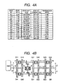
- Fig. 4 shows an example of the transmission ratio gained by the setting gear ratio and its combination thereof. It meets the aforementioned two restrictions and corresponds to Fig. 3 .
- the definition of each gear ratio is given in the figure attached to Fig. 4 .
- the transmission ratio in the assist mode is slightly smaller than the median value of the transmission ratio in the drive mode. This is because the planned value is intentionally misaligned, giving consideration to the motor inverter efficiency. After having aligned the following center distances, the misalignment was at most 2% or so, although it was further increased from the planned value.
- Fig. 5 shows the radius r1 through r18 of transmission gears for realizing these gear ratios, and the center distances L1 through L4 determined thereby.
- the radius and center distance are defined in the figure attached to Fig. 4 .
- the center distance L1 is equal with respect to transmission gears 40 and 41
- the center distance L4 is equal with respect to transmission gears 54 and 55; therefore, transmission gears 40 and 41 and transmission gears 54 and 55 can be made to mesh each other from both sides of the input gears 37 and 38.
- the center distance L2 is equal with respect to the transmission gears 42 through 45, and the center distance L3 is equal with respect to the transmission gears 56 through 58; therefore, these gears can be made to mesh with each other from both sides of the driven gears 49 through 52.
- the transmission gear 59 is used for backing up, and an idler is inserted, so there is no need of giving consideration to the center distance L3.
- Fig. 2 permits a variety of combinations in addition of the combination given in Fig. 3 ( Fig. 4 ).
- Fig. 6 shows the combinations other than those given above.
- a variety of intermediate transmission ratios can be obtained. They are transmission ratios for the engine, and this transmission also changes transmission ratio for the motor.
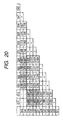
- Fig. 7 shows all combinations including the transmission ratio for the motor. The portion enclosed by bold frames indicates transmission ratio with respect to the motor. The other shows the gear ratio with respect to the engine. The crosshatched section shows the mode where the engine torque is transferred through the motor.
- the bold characters show the combinations of Fig. 3 ( Fig. 4 ).
- Combinations of the G11 and G12, and G41 and G42 are also possible. Transmission ratio between the engine and motor is shown.
- the transmission shown in Fig. 2 is capable of 48 transmissions ratios.
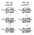
- Fig. 8 shows changes in the combination when a 2-step jump-over gear shift is performed in the present transmission.
- the jump-over gear shift is normally carried out by rapid step-on gas pedal, so downshift is shown.
- a completely reverse process is taken for jump-over upshift.
- lift foot upshift where gas pedal is released, there is no problem with torque interruption. All that is needed is jumping over to the mode required in the line of transmission.
- the same mode as that in the sequential shift of Fig. 1 can be used for 5-3 shift and 4-2 shift.
- the same mode as shown in Fig. 3 is to be used for 3-1 shift, simultaneous changes of two dog clutches will occur, with the result that torque interruption takes place.
- gear shift is performed from 3 to 1.2 through 1.7. This method provides satisfactory gear shift without causing torque interruption.
- Fig. 9 represents the changes in combinations for 3-step jump-over gear shift in the present transmission. Since the 3-step jump-over gear shift is required for kick-down, the down shift is shown. In this case, 5-2 shift is performed in the same mode as that in the sequential shift of Fig. 3 . If the same mode as that of Fig. 3 is to be used for 4-1 shift, torque interruption occurs. If gear shift is performed from 4 to 1.2 through 2.4, satisfactory gear shift can be provided without causing torque interruption.
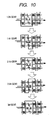
- Fig. 10 shows the upshift after jump-over gear shift.
- 1.2th gear is obtained by combinations of G41 and G31.
- upshift is carried out by acceleration. In this case, 1.2 is reached through 1.4 by the process shown in Fig. 10 . Further, 3rd gear is reached through 2.6. After that, one can go back to the process shown in Fig. 3 .
- Fig. 11 is a flowchart representing an example of power-on upshift from 1 to 2.
- Fig. 12A is a time chart representing the changes in the torques and speeds of various sections in this case, in the form corresponding to the steps given in Fig. 11 .
- Figs. 12B again shows the changes in the torque transmission route of upshift from 1 to 2 shown in Fig. 3 and meshing clutch.
- Step 1 while the car is driving with the transmission gears 40 (G11) and 42 (G21) engaged, the motor speed is controlled to change the revolutionary speed N2 of the second intermediate shaft 53, as shown in Fig. 12B .
- Step 2 evaluation is made to determine that the revolutionary speed N2 of the second intermediate shaft 53 has been synchronized with the revolutionary speed of the transmission gear 55 (G42).
- Step 3 the transmission control unit 8 actuates the shift actuator 66, and moves the dog clutch 60 rightward, as shown in the drawing.
- Step 4 if motor torque is increased in the negative direction (a driving force for the output shaft, and a load for the engine), the input torque of the transmission gear 55 (G42) will be increased, and the input torque of the transmission gear 40 (G11) will be reduced, as shown in the timing chart of Fig. 12 .
- Step 5 the transmission control unit 8 determines if the torque transfer 1 has terminated or not. It is intended to determine if the input torque of the transmission gear 40 (G11) has been reduced to zero or not. However, since it often happens that the input torque of the gear cannot be directly detected, the input torque of the gear can be considered as "0", when the value of the motor transfer torque expressed in terms of the engine shaft has reached the value equal to the absolute value of the engine torque. For this purpose, it is necessary to get the engine torque Te in advance by detection or calculation. Its specific method is shown in the Japanese Patent Laid-Open No. Hei 05-240073 and Japanese Patent Laid-Open No. Hei 06-317242 , and will not be described here.
- Step 6 the transmission control unit 8 operates the shift actuator 63, as shown in Fig. 12B , and releases the transmission gear 40 (G11) . Easy release is possible from the state of torque being zero. There is no change to the operation of the transmission. When the transmission gear 40 (G11) has been released, the engine speed can be changed.
- Step 7 when the transmission control unit 8 issues a motor speed change command, the engine speed is changed toward the revolutionary speed of second gear. This is a speed change process called inertia phase.
- the G12 indicates the gear ratio of the transmission gear 41.
- Equation 1 and Equation 2 The (N1 - N2) obtained from Equation 1 and Equation 2 was a negative value, but the (N1 - N2') obtained from Equation 1 and Equation 3 was 0.181 ⁇ No, a negative value.
- the direction of motor rotation was changed halfway through the rotation so that the speed of the transmission gear 41 (G12) was changed to N1.
- Step 8 the transmission control unit 8 determines if the speed change has terminated or not. This determination is made by checking if the speed of the input shaft 36, i.e. the engine speed Ne has been synchronized with the (N1 ⁇ G12) or not.
- Step 9 the transmission control unit 8 operates the shift actuator 63 so that the dog clutch 46 of the transmission gear 41 (G12) will be engaged. Since it is in the synchronized state, it can be easily engaged, without giving any change to the operation of the transmission.
- Step 10 the transmission control unit 8 issues the motor torque reduction command.
- the motor torque is reduced to "0" as shown by the speed change in the time chart 2 of Fig. 12A
- the engine torque transferred to the transmission gear 55 (G42) through the motor 5 moves to the transmission gear 41 (G12), as shown in Fig. 12B .
- Step 11 the transmission control unit 8 determines that the torque change 2 has terminated, since the motor torque has been reduced to "0".
- Step 12 the transmission control unit 8 operates the shift actuator 66 and releases the transmission gear 55 (G42), thereby terminating the gear shift. Since the motor torque is in the state of "0", easy release can be achieved, without giving any change to the operation of the transmission.
- the description refers to the case of 1-2 upshift.
- the upshift up to 5th gear and downshift as well as jump-over gear shift can be performed in identically the same manner.
- Fig. 13 shows the motor control system.
- the motor 5 is a permanent magnetic synchronous motor, for example.
- Three-phase alternating current U, V and W are supplied by motor control equipment 7.
- Each arm of the inverter of the motor control equipment 7 is provided with a high speed switching device 32 so that the d.c. voltage of a battery 6 is converted into 3-phase voltage of variable frequency.
- the inverter control unit 33 controls the duty of the inverter, and feeds back the output of the current sensor 34 of each arm and the output of the angle detecting position sensor 35 of the rotor so that the torque and speed of the motor 5 will conform to the commands.
- Such control is a known art in the field of power electronics, and will not be described.
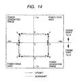
- Fig. 14 shows the relationship between motor torque and speed. What is called “4-quadrant control” is provided by the motor control equipment 7.
- the area is the so-called engine braking area where the engine absorbs driving force, so the operating point moves to the first and second quadrants in Fig. 14 .
- the type of the motor is not restricted to the permanent magnetic synchronous motor so long as 4-quadrant control can be provided. It goes without saying that an induction motor or d.c. motor can be used.
- Fig. 15 is a block diagram representing the transmission 2 as a second embodiment of the present invention. What is different from Fig. 2 is that the transmission gear 40 of the first intermediate shaft 39 is used for backing up. Instead, gear ratio of the transmission gear 59 second intermediate shaft 53 is reduced to be used for sixth gear.
- Fig. 16 shows an example of the operation mode of this transmission.
- the gear ratio is determined by a combination of two transmission gears.
- the engine torque is transferred from the input shaft 36 to either the first intermediate shaft 39 or second intermediate shaft 53, and is transferred from that intermediate shaft directly the output shaft 3.
- This mode is the drive mode, on the one hand.
- the assist mode is the mode where the engine torque is transferred to the output shaft 3 after having been transferred to another intermediate shaft through the motor. This is the same as the case in Fig. 3 .
- the 1st, 2nd, 3rd, 4th, 5th and 6th gears are in the drive mode, while 0.5th, 1.5th, 2.5th, 3.5th, 4.5th and 5.5th gears are in the assist mode.
- Fig. 17 shows an example of the transmission ratio obtained from the set gear ratio and the combination thereof. It meets the aforementioned two restrictions and corresponds to Fig. 16 .
- the definition of each gear ratio is shown in Fig. 17B .
- the transmission ratio in the assist mode is slightly smaller than the median value of the transmission ratio in the drive mode. This is because the planned value is intentionally misaligned, giving consideration to the motor inverter efficiency. After having aligned the following center distances, the misalignment was at most 10% or so, although it was further increased from the planned value.
- Fig. 18 shows radiuses r1 through r18 of transmission gears for achieving these gear ratios and center distances L1 through L4 determined thereby.
- the radius and center distances are defined in the drawing attached to Fig. 17B . Since the transmission gear 40 has an idler, the center distance L1 can be determined by giving consideration only to the transmission gear 41. Since center distance L4 is equal with respect to the transmission gears 54 and 55, transmission gears 40 and 41 and transmission gears 54 and 55 can be made to mesh each other from both sides of the input gears 37 and 38.
- the center distance L2 is equal with respect to the transmission gears 42 through 45, and the center distance L3 is equal with respect to the transmission gears 56 through 58; therefore, these gears can be made to mesh with each other from both sides of the driven gears 49 through 52.
- the transmission shown in Fig. 15 permits a variety of gear combinations in addition of the combination given in Fig. 17 .
- Fig. 19 shows the combinations other than those given above.
- a variety of intermediate transmission ratios can be obtained. They are transmission ratios for the engine, and this transmission also changes transmission ratio for the motor.
- Fig. 20 shows all combinations including the transmission ratios for the motor. The portion enclosed by bold frames indicates transmission ratio with respect to the motor. The other shows the gear ratio with respect to the engine. The crosshatched section shows the mode where the engine torque is transferred through the motor. The bold characters show the combinations of Fig. 17 .
- Combinations of the G11 and G12, and G41 and G42 are also possible. Transmission ratio between the engine and motor is shown. This is possible when only one gear on the output shaft side is connected.
- connection is prohibited. This is indicated by "-”.
- the combination marked with “ ⁇ ” refers to the case of double meshing, and revolution is disabled in this state.
- the transmission shown in Fig. 15 is capable of 48 transmissions ratios.
- jump-over shift is also possible. It is apparent from Fig. 16 that 6-4 shift is performed through 4.5th gear, 5-3 and 4-2 shift through 3.5th gear, and 3-1 shift through 2.5th or 1.5th gear.
- the 3-step jump-over shift is also performed in a similar manner. It is apparent from Fig. 16 that 6-3 shift is performed through 5.5th gear, and 5-2 and 4-1 shift through 3.5th gear.
- jump-over gear shift is a gear shift without torque applied.
- the gear may be shifted directly to the desired step.
- the present embodiment provides the advantage that the gear shift step can be expanded up to sixth gear and, at the same time, jump-over gear shift can be easily controlled without using the irregular secondary gear shift step.
- the present embodiment allows the engine and transmission to be disconnected, without increasing the number of dog clutches. This increases the efficiency of regenerative braking and provides a substantial economical advantage. It also allows the transmission ratio of 1st through 5th gear to be designed in the same manner as before. Further, a large number of secondary transmission ratios can be obtained. Moreover, this is used to perform jump-over gear shift.
- the motor speed can be changed independently of the engine. This increases the motor efficiency and provides a substantial economical advantage.
Landscapes
- Engineering & Computer Science (AREA)
- Mechanical Engineering (AREA)
- Chemical & Material Sciences (AREA)
- Combustion & Propulsion (AREA)
- Transportation (AREA)
- General Engineering & Computer Science (AREA)
- Automation & Control Theory (AREA)
- Structure Of Transmissions (AREA)
- Hybrid Electric Vehicles (AREA)
- Control Of Transmission Device (AREA)
- Electric Propulsion And Braking For Vehicles (AREA)
- Arrangement Of Transmissions (AREA)
Claims (10)
- Getriebe mit:einer Antriebswelle (36), die mit einem Motor (1) gekoppelt ist;einem Satz Antriebsräder, die auf der Antriebswelle (36) angeordnet sind;einer ersten Zwischenwelle (39);einem ersten Satz Getrieberäder, die mit der ersten Zwischenwelle gekoppelt oder von ihr abgekoppelt sind, die mit dem Satz Antriebsräder ineinander greifen;einer zweiten Zwischenwelle (53);einem zweiten Satz Getrieberäder, die mit der zweiten Zwischenwelle (53) gekoppelt oder von ihr abgekoppelt sind, die mit dem Satz Antriebsrädern ineinander greifen;einem dritten Satz Getrieberäder, die auf der ersten Zwischenwelle (39) angeordnet und mit der ersten Zwischenwelle (39) gekoppelt oder von ihr abgekoppelt sind;einem vierten Satz Getrieberäder, die auf der zweiten Zwischenwelle (53) angeordnet und mit der zweiten Zwischenwelle (53) gekoppelt oder von ihr abgekoppelt sind;einem Satz Abtriebsräder, die mit Rädern aus dem dritten und vierten Satz Getrieberäder ineinander greifen;einer Abtriebswelle (3), die allgemein mit den Abtriebsrädern gekoppelt ist;einem Differenzialgetriebe (31), das mit den ersten und zweiten Zwischenwellen (39, 53) gekoppelt ist; undeinem Motor (5), der mit der dritten Welle des Differenzialgetriebes (31) gekoppelt ist, um ein Drehmoment im Verhältnis zu der ersten und zweiten Zwischenwelle (39, 53) auszuüben.
- Getriebe nach Anspruch 1, dadurch gekennzeichnet, dass es Folgendes umfasst:zwei Antriebsräder (37, 38) in dem Satz Antriebsräder, die auf der Antriebswelle (36) angeordnet sind;zwei erste Getrieberäder (40, 41) in dem ersten Satz Getrieberäder, die jeweils mit den zwei Antriebsrädern (37, 38) ineinander greifen;zwei zweite Getrieberäder (54, 55) in dem zweiten Satz Getrieberäder;zwei dritte Getrieberäder (42, 43) in dem dritten Satz Getrieberäder undzwei vierte Getrieberäder (56, 57) in dem vierten Satz Getrieberäder.
- Getriebe nach Anspruch 2, wobei die zwei ersten Getrieberäder in dem ersten Satz Getrieberäder verschiedene Drehrichtungen aufweisen und wobei die zwei ersten Getrieberäder mit der ersten Zwischenwelle gekoppelt oder von ihr abgekoppelt sind, wobei eine erste Klauenkupplung jeweils mit den Getrieberädern ineinander greift;
wobei die zwei zweiten Getrieberäder in dem zweiten Satz Getrieberäder verschiedene Übersetzungsverhältnisse aufweisen und wobei die zwei zweiten Getrieberäder mit der zweiten Zwischenwelle gekoppelt oder von ihr abgekoppelt sind, wobei eine zweite Klauenkupplung jeweils mit den Getrieberädern ineinander greift. - Getriebe nach einem der Ansprüche 1, 2 und 3, wobei ein Hilfsmodus-Übersetzungsverhältnis weniger als einen Medianwert eines Antriebsmodus-Übersetzungsverhältnisses beträgt.
- Steuereinrichtung zum Steuern eines Getriebes nach einem der Ansprüche 1 bis 4,
wobei die Steuereinrichtung (8) folgende Schritte ausführt:Einrücken des zweiten Getrieberads des zweiten Satzes Getrieberäder während des Antriebsmodus des Einrückens eines ersten Getrieberads des ersten Satzes Getrieberäder und Einrücken eines ersten Getrieberads der dritten Getrieberäder;Erhöhen des Drehmoments des Motors (5), dadurch Verschieben des Übersetzungsdrehmoments des ersten Getrieberads des ersten Satzes Getrieberäder zu dem zweiten Getrieberad des zweiten Satzes Getrieberäder;Ausrücken des ersten Getrieberads des ersten Satzes Getrieberäder, wenn das Übersetzungsdrehmoment des ersten Getrieberads des ersten Satzes Getrieberäder auf nahe Null reduziert worden ist;allmähliches Annähern der Drehzahl der ersten Zwischenwelle (39) an das zweite Getrieberad des ersten Satzes Getrieberäder, während das Abtriebswellendrehmoment von dem Motor (5) aufrechterhalten wird;Verbinden eines zweiten Getrieberads des ersten Satzes Getrieberäder, wenn die Drehzahl der ersten Zwischenwelle (39) mit derjenigen des zweiten Getrieberads des ersten Satzes Getrieberäder synchron geworden ist; undReduzieren des von dem Motor (5) erzeugten Drehmoments auf Null, dadurch Abkoppeln des zweiten Getrieberads des zweiten Satzes Getrieberäder. - Steuereinrichtung zum Steuern eines Getriebes nach einem der Ansprüche 1 bis 4,
wobei die Steuereinrichtung (8) dazu konfiguriert ist, die folgenden Schritte auszuführen:Einrücken des ersten Getrieberads des vierten Satzes Getrieberäder während des Antriebsmodus des Einrückens des zweiten Getrieberads des ersten Satzes Getrieberäder und Einrücken des ersten Getrieberads des dritten Satzes Getrieberäder;Erhöhen des Drehmoments des Motors (5); dadurch Verschieben des Übersetzungsdrehmoments des ersten Getrieberads des dritten Satzes Getrieberäder zu dem ersten Getrieberad des vierten Satzes Getrieberäder;Ausrücken des ersten Getrieberads des dritten Satzes Getrieberäder, wenn das Übersetzungsdrehmoment des ersten Getrieberads des dritten Satzes Getrieberäder auf nahe Null reduziert worden ist;allmähliches Annähern der Drehzahl der ersten Zwischenwelle (39) an das zweite Getrieberad des dritten Satzes Getrieberäder, während das Abtriebswellendrehmoment von dem Motor (5) aufrechterhalten wird;Verbinden des zweiten Getrieberads des dritten Satzes Getrieberäder, wenn die Drehzahl der ersten Zwischenwelle (39) mit derjenigen des zweiten Getrieberads des dritten Satzes Getrieberäder synchron geworden ist; undReduzieren des von dem Motor (5) erzeugten Drehmoments auf Null, dadurch Abkoppeln des ersten Getrieberads des vierten Satzes Getrieberäder. - Steuereinrichtung zum Steuern eines Getriebes nach einem der Ansprüche 1 bis 4,
wobei die Steuereinrichtung (7) dadurch gekennzeichnet ist, dass, wenn von dem Motor (5) durch das Drehmoment der Abtriebswelle (3) eine Regeneration vorgesehen wird, der erste Satz Getrieberäder und die erste Zwischenwelle (39) ausgerückt werden und der zweite Satz Getrieberäder und die zweite Zwischenwelle (53) ausgerückt werden. - Steuereinrichtung zum Steuern eines Getriebes nach einem der Ansprüche 1 bis 4, wobei die Steuereinrichtung dazu konfiguriert ist, die folgenden Schritte durchzuführen:Einrücken eines ersten Rads des ersten Satzes Getrieberäder;Einrücken eines ersten Getrieberads des dritten Satzes Getrieberäder;Einrücken eines ersten Getrieberads des vierten Satzes Getrieberäder während eines Antriebsvorgangs;Erhöhen des Drehmoments des Motors; dadurch Verschieben eines Übersetzungsdrehmoments des ersten Getrieberads des dritten Satzes Getrieberäder zu dem ersten Getrieberad des vierten Satzes Getrieberäder;Ausrücken des ersten Getrieberads des dritten Satzes Getrieberäder, wenn dessen Übersetzungsdrehmoment auf nahe Null reduziert worden ist;allmähliches Annähern einer Drehzahl der ersten Zwischenwelle (39) an ein zweites Getrieberad des dritten Satzes Getrieberäder, während ein Abtriebswellendrehmoment durch den Motor aufrechterhalten wird;Verbinden des zweiten Getrieberads des dritten Satzes Getrieberäder, wenn die Drehzahl der ersten Zwischenwelle mit derjenigen des zweiten Getrieberads des dritten Satzes Getrieberäder synchron geworden ist; undReduzieren des von dem Motor erzeugten Drehmoments auf Null, dadurch Abkoppeln des ersten Getrieberads des vierten Satzes Getrieberäder.
- Personenkraftwagen mit:einem Motor (1);einer elektrisch gesteuerten Drosselklappe (10), die an dem Motor (1) angeordnet ist;einer Motorsteuervorrichtung (8) zum Steuern der Drosselklappe (10);einem Getriebe nach einem der Ansprüche 1 bis 4 undeiner Motorsteuereinrichtung (7) zum Steuern des Motors (5);wobei der Personenkraftwagen dadurch gekennzeichnet ist, dass die Motorsteuereinrichtung (7) das Drehmoment und die Drehzahl des Motors (5) so steuert, dass die Motorleistung zu dem nächsten Positionsrad verschoben wird, wodurch die Geschwindigkeit geändert wird.
- Personenkraftwagen nach Anspruch 9, wobei zumindest eine Gangstufe von Antriebsmodi zwischen Gangstufen vor und nach einem Gangschaltvorgang vorgesehen ist.
Applications Claiming Priority (2)
| Application Number | Priority Date | Filing Date | Title |
|---|---|---|---|
| JP2003312078 | 2003-09-04 | ||
| JP2003312078A JP4038460B2 (ja) | 2003-09-04 | 2003-09-04 | アクティブシフト変速機,変速機制御装置、および自動車 |
Publications (3)
| Publication Number | Publication Date |
|---|---|
| EP1512884A2 EP1512884A2 (de) | 2005-03-09 |
| EP1512884A3 EP1512884A3 (de) | 2007-01-17 |
| EP1512884B1 true EP1512884B1 (de) | 2010-06-30 |
Family
ID=34131851
Family Applications (1)
| Application Number | Title | Priority Date | Filing Date |
|---|---|---|---|
| EP04019182A Expired - Lifetime EP1512884B1 (de) | 2003-09-04 | 2004-08-12 | Aktivschaltgetriebe, Getriebesteuergerät und Kraftfahrzeug |
Country Status (4)
| Country | Link |
|---|---|
| US (2) | US7226379B2 (de) |
| EP (1) | EP1512884B1 (de) |
| JP (1) | JP4038460B2 (de) |
| DE (1) | DE602004027874D1 (de) |
Families Citing this family (65)
| Publication number | Priority date | Publication date | Assignee | Title |
|---|---|---|---|---|
| CN101526127B (zh) | 2001-04-26 | 2011-08-17 | 瀑溪技术公司 | 连续可变变速器及部件支撑件、支撑框架及框架制作方法 |
| JP4375001B2 (ja) * | 2003-12-04 | 2009-12-02 | 株式会社日立製作所 | 自動車の駆動装置および駆動方法 |
| SE524975C2 (sv) * | 2003-12-17 | 2004-11-02 | Volvo Lastvagnar Ab | Automatiskt växlingsförfarande för fordon med inkopplat kopplingsberoende kraftuttag samt automatiskt urkopplingsförfarande av ett kopplingsberoende kraftuttag |
| JP2006214454A (ja) * | 2005-02-01 | 2006-08-17 | Hitachi Ltd | 自動車の変速機制御装置及び自動変速装置 |
| KR101831828B1 (ko) | 2005-10-28 | 2018-02-23 | 폴브룩 인텔렉츄얼 프로퍼티 컴퍼니 엘엘씨 | 전동 드라이브 |
| EP1998974B1 (de) * | 2005-11-15 | 2014-05-21 | Stridsberg Powertrain AB | Hybridfahrzeug mit weichen wellen |
| CA2976893C (en) | 2005-12-09 | 2019-03-12 | Fallbrook Intellectual Property Company Llc | Continuously variable transmission |
| JP2007177925A (ja) * | 2005-12-28 | 2007-07-12 | Hitachi Ltd | 自動車の制御装置,制御方法、及び自動変速機 |
| EP1811202A1 (de) | 2005-12-30 | 2007-07-25 | Fallbrook Technologies, Inc. | Stufenloses Getriebe |
| JP4887058B2 (ja) * | 2006-02-22 | 2012-02-29 | 日立オートモティブシステムズ株式会社 | 自動車の制御装置及び制御方法 |
| JP4775242B2 (ja) * | 2006-12-07 | 2011-09-21 | マツダ株式会社 | 車両用駆動装置 |
| DE102007002739A1 (de) * | 2007-01-18 | 2008-07-24 | Robert Bosch Gmbh | Verfahren zur Drehzahlveränderung eines Antriebs eines Fahrzeugs |
| JP4150055B1 (ja) | 2007-04-05 | 2008-09-17 | 北海道旅客鉄道株式会社 | 軌道車両用駆動システム及びそれを用いた軌道車両 |
| CN102943855B (zh) | 2007-04-24 | 2016-01-27 | 福博科技术公司 | 电力牵引传动装置 |
| JP2009036354A (ja) * | 2007-08-03 | 2009-02-19 | Hokkaido Railway Co | ハイブリッド車両用動力伝達システムの制御方法 |
| KR100945660B1 (ko) | 2007-08-09 | 2010-03-04 | 김정규 | 차동기어 변속기 |
| US8996263B2 (en) | 2007-11-16 | 2015-03-31 | Fallbrook Intellectual Property Company Llc | Controller for variable transmission |
| CA2716908C (en) | 2008-02-29 | 2017-06-27 | Fallbrook Technologies Inc. | Continuously and/or infinitely variable transmissions and methods therefor |
| JP5213575B2 (ja) * | 2008-07-31 | 2013-06-19 | 北海道旅客鉄道株式会社 | ハイブリッド車両用動力伝達システムの制御方法 |
| JP5291414B2 (ja) * | 2008-09-16 | 2013-09-18 | 北海道旅客鉄道株式会社 | 軌道車両用駆動システム及び軌道車両 |
| JP5312481B2 (ja) * | 2008-12-18 | 2013-10-09 | 本田技研工業株式会社 | ハイブリット車両の動力伝達装置 |
| US8070649B2 (en) * | 2009-01-09 | 2011-12-06 | GM Global Technology Operations LLC | Hybrid powertrain and dual clutch transmission |
| US7975780B2 (en) * | 2009-01-27 | 2011-07-12 | Schlumberger Technology Corporation | Adjustable downhole motors and methods for use |
| JP5155910B2 (ja) * | 2009-03-11 | 2013-03-06 | 株式会社日立ニコトランスミッション | 大型車両用ツインクラッチ式変速機 |
| KR100965101B1 (ko) * | 2009-11-09 | 2010-06-22 | 조재민 | 2개의 회전동력원과 기어결합체를 이용한 변속장치 |
| KR100965102B1 (ko) * | 2009-11-26 | 2010-06-22 | 조재민 | 2개의 제어수단과 기어결합체를 이용한 변속장치 |
| US8813593B2 (en) * | 2009-11-30 | 2014-08-26 | Eaton Corporation | Adapter for connecting a countershaft transmission with a hydraulic launch assist system |
| US8621959B2 (en) * | 2010-01-21 | 2014-01-07 | GM Global Technology Operations LLC | Compact active material actuated transmissions for driving multiple output loads from a single primary actuator |
| KR100982934B1 (ko) | 2010-03-30 | 2010-09-17 | 강성원 | 2개의 회전동력원과 기어결합체를 이용한 변속장치 |
| KR101002175B1 (ko) * | 2010-08-31 | 2010-12-17 | 강성원 | 단일 종류의 회전동력원과 기어결합체를 이용한 변속장치 |
| JP5587719B2 (ja) * | 2010-09-30 | 2014-09-10 | 株式会社日立ニコトランスミッション | 車両用動力伝達システムの制御方法及び装置 |
| US8888643B2 (en) | 2010-11-10 | 2014-11-18 | Fallbrook Intellectual Property Company Llc | Continuously variable transmission |
| DE102010061823B4 (de) * | 2010-11-24 | 2020-02-13 | Zf Friedrichshafen Ag | Verfahren zum Betreiben eines Antriebsstrangs |
| KR101037050B1 (ko) | 2010-12-10 | 2011-05-26 | 강성원 | 셀프 로킹수단이 구비된 기어결합체를 이용한 감속장치 |
| EP2500603A1 (de) * | 2011-03-15 | 2012-09-19 | C.R.F. Società Consortile per Azioni | Gangschaltvorrichtung für Kraftfahrzeug |
| EP2505410A1 (de) * | 2011-04-01 | 2012-10-03 | Imperia Automobiles SA | Antriebsanlage für Hybridfahrzeug |
| KR101316269B1 (ko) | 2011-06-20 | 2013-10-08 | 현대자동차주식회사 | 자동화 수동변속기 |
| US8622867B1 (en) * | 2011-12-20 | 2014-01-07 | Lei Yang | Differential with torque distribution |
| US9254837B2 (en) * | 2012-04-04 | 2016-02-09 | Toyota Jidosha Kabushiki Kaisha | Driving device for vehicle |
| CZ2012313A3 (cs) * | 2012-05-11 | 2013-05-29 | Zetor Tractors A.S. | Usporádání reverzacní dvoutoké prevodovky, zejména pro motorová vozidla a stavební stroje, s dvema vetvemi toku výkonu |
| RU2015125350A (ru) * | 2012-11-29 | 2017-01-11 | Мак Тракс, Инк. | Последовательная гибридная трансмиссия и способ переключения передач для такой трансмиссии |
| KR101398558B1 (ko) * | 2013-01-23 | 2014-05-27 | 현경열 | 다단 자동 변속기 |
| US8696512B1 (en) * | 2013-03-08 | 2014-04-15 | GM Global Technology Operations LLC | Powertrain architecture-powersplit hybrid using a single motor |
| CN103267089A (zh) * | 2013-06-13 | 2013-08-28 | 郭质刚 | 多离合器式变速传动装置 |
| DE102014223914B4 (de) * | 2014-11-25 | 2016-08-25 | Bayerische Motoren Werke Aktiengesellschaft | Schaltgetriebeeinrichtung mit kompaktem Aufbau |
| DE102014223912B4 (de) * | 2014-11-25 | 2021-09-30 | Bayerische Motoren Werke Aktiengesellschaft | Schaltgetriebeeinrichtung mit Zugmittelgetriebe |
| KR101684059B1 (ko) | 2015-02-05 | 2016-12-08 | 현대자동차주식회사 | 차량용 변속기 |
| KR101684060B1 (ko) | 2015-02-05 | 2016-12-08 | 현대자동차주식회사 | 차량용 변속기 |
| KR101646463B1 (ko) * | 2015-05-07 | 2016-08-05 | 현대자동차주식회사 | 하이브리드 차량용 동력 전달 시스템 |
| US10047861B2 (en) | 2016-01-15 | 2018-08-14 | Fallbrook Intellectual Property Company Llc | Systems and methods for controlling rollback in continuously variable transmissions |
| US10023266B2 (en) | 2016-05-11 | 2018-07-17 | Fallbrook Intellectual Property Company Llc | Systems and methods for automatic configuration and automatic calibration of continuously variable transmissions and bicycles having continuously variable transmissions |
| KR101756023B1 (ko) | 2016-06-02 | 2017-07-10 | 현대자동차주식회사 | 차량용 변속기 |
| KR101795291B1 (ko) | 2016-07-27 | 2017-11-08 | 현대자동차주식회사 | 차량용 변속기 |
| JP6621725B2 (ja) * | 2016-09-15 | 2019-12-18 | トヨタ自動車株式会社 | 車両用変速機 |
| US10737696B2 (en) * | 2016-12-22 | 2020-08-11 | Eaton Cummins Automated Transmission Technologies, Llc | System, method, and apparatus for operating a high efficiency, high output transmission |
| US11215268B2 (en) | 2018-11-06 | 2022-01-04 | Fallbrook Intellectual Property Company Llc | Continuously variable transmissions, synchronous shifting, twin countershafts and methods for control of same |
| US11174922B2 (en) | 2019-02-26 | 2021-11-16 | Fallbrook Intellectual Property Company Llc | Reversible variable drives and systems and methods for control in forward and reverse directions |
| CN110345222B (zh) * | 2019-07-10 | 2020-08-28 | 宁波上中下自动变速器有限公司 | 车辆自动变速器传动系统及车辆 |
| US10989288B1 (en) | 2019-10-07 | 2021-04-27 | Arvinmeritor Technology, Llc | Axle assembly having a multi-speed countershaft transmission |
| US11209072B2 (en) | 2019-10-07 | 2021-12-28 | Arvinmeritor Technology, Llc | Axle assembly having a multi-speed transmission |
| US11207976B2 (en) * | 2019-10-07 | 2021-12-28 | Arvinmeritor Technology, Llc | Axle assembly having a multi-speed countershaft transmission |
| US11441644B2 (en) | 2019-10-07 | 2022-09-13 | Arvinmeritor Technology, Llc | Axle assembly having a multi-speed transmission and a drop gear set |
| DE102020214163A1 (de) * | 2020-11-11 | 2022-05-12 | Robert Bosch Gesellschaft mit beschränkter Haftung | Verfahren zur Schaltung eines Übersetzungsverhältnisses eines schaltbaren Getriebes, Steuergerät und Fahrzeug |
| US11371588B1 (en) | 2021-02-22 | 2022-06-28 | Arvinmeritor Technology, Llc | Axle assembly having a barrel cam |
| US11608877B2 (en) | 2021-02-22 | 2023-03-21 | Arvinmeritor Technology, Llc | Axle assembly having a sector cam |
Family Cites Families (11)
| Publication number | Priority date | Publication date | Assignee | Title |
|---|---|---|---|---|
| DE59710076D1 (de) * | 1996-11-30 | 2003-06-18 | Volkswagen Ag | Kontinuierlich verstellbares Stufenwechselgetriebe |
| DE19850549A1 (de) * | 1998-11-03 | 2000-05-04 | Bosch Gmbh Robert | Getriebe für ein Kraftfahrzeug, insbesondere Doppelkupplungs-Schaltgetriebe, und Verfahren zum Betreiben des Getriebes |
| DE19940288C1 (de) * | 1999-08-25 | 2001-03-15 | Daimler Chrysler Ag | Doppelkupplungs-Mehrganggetriebe |
| JP3647399B2 (ja) | 2000-09-14 | 2005-05-11 | 株式会社日立製作所 | 車両用動力伝達システムおよびそれを搭載した自動車 |
| EP1270301A3 (de) * | 2001-06-19 | 2007-02-21 | Hitachi, Ltd. | Kraftfahrzeuggetriebe mit Schaltungen ohne Drehmoment Unterbrechung |
| DE10133919A1 (de) * | 2001-07-12 | 2003-01-23 | Bayerische Motoren Werke Ag | Elektromechanisches Getriebe |
| JP4205878B2 (ja) | 2001-08-31 | 2009-01-07 | 本田技研工業株式会社 | ハイブリッド型車両の動力伝達装置及びその制御方法 |
| JP3988428B2 (ja) * | 2001-10-09 | 2007-10-10 | 株式会社日立製作所 | 自動変速機,制御装置、および自動車 |
| US6945893B2 (en) * | 2002-05-28 | 2005-09-20 | Eaton Corporation | Hybrid powertrain system |
| JP3639829B2 (ja) * | 2002-12-09 | 2005-04-20 | 株式会社日立製作所 | 自動変速システムおよび自動車 |
| JP4375001B2 (ja) * | 2003-12-04 | 2009-12-02 | 株式会社日立製作所 | 自動車の駆動装置および駆動方法 |
-
2003
- 2003-09-04 JP JP2003312078A patent/JP4038460B2/ja not_active Expired - Fee Related
-
2004
- 2004-08-12 EP EP04019182A patent/EP1512884B1/de not_active Expired - Lifetime
- 2004-08-12 DE DE602004027874T patent/DE602004027874D1/de not_active Expired - Lifetime
- 2004-08-18 US US10/920,248 patent/US7226379B2/en not_active Expired - Lifetime
-
2007
- 2007-06-04 US US11/757,435 patent/US7331897B2/en not_active Expired - Lifetime
Also Published As
| Publication number | Publication date |
|---|---|
| JP4038460B2 (ja) | 2008-01-23 |
| JP2005076875A (ja) | 2005-03-24 |
| US7331897B2 (en) | 2008-02-19 |
| US20070232434A1 (en) | 2007-10-04 |
| DE602004027874D1 (de) | 2010-08-12 |
| US7226379B2 (en) | 2007-06-05 |
| US20050050974A1 (en) | 2005-03-10 |
| EP1512884A3 (de) | 2007-01-17 |
| EP1512884A2 (de) | 2005-03-09 |
Similar Documents
| Publication | Publication Date | Title |
|---|---|---|
| US7226379B2 (en) | Active shift transmission, transmission control unit and automobile | |
| EP1302697A2 (de) | Automatikgetriebe, Steuergerät und Fahrzeug | |
| CN108382188B (zh) | 混合动力汽车动力系统及其控制方法 | |
| EP1541900B1 (de) | Fahrzeug-Antriebssystem und Schaltverfahren | |
| JP4466514B2 (ja) | ハイブリッド車両のエンジン始動制御装置 | |
| CN108137033B (zh) | 用于运行驱动设备的方法和设备以及驱动设备 | |
| EP1429049B1 (de) | Automatikgetriebe und Fahrzeug mit einem solchen System | |
| US9216734B2 (en) | Control device | |
| EP2067680A2 (de) | Fahrzeugsteuerungsvorrichtung und mit der Steuerungsvorrichtung ausgestattetes Fahrzeug | |
| US20050139035A1 (en) | Double clutch transmission for a hybrid electric vehicle and method for operating the same | |
| CN101754882A (zh) | 在带有电力驱动装置的车辆中执行按负载换挡的方法 | |
| EP1826462A2 (de) | Vorrichtung und Verfahren zur Fahrzeugsteuerung | |
| CN104507776A (zh) | 电动车辆的变速控制装置 | |
| CN107735600A (zh) | 混合动力车辆的变速控制装置 | |
| EP3566919A1 (de) | Geschwindigkeitsänderungssteuerungssystem für ein fahrzeug | |
| JP2010188786A (ja) | ハイブリッド車両の変速制御装置および変速制御方法 | |
| JP2003335152A (ja) | ハイブリッド自動車の変速制御方法及び変速制御装置 | |
| JP2004150450A (ja) | ハイブリッド電気自動車の変速制御装置 | |
| JP4130906B2 (ja) | 変速機の制御装置,変速機、および自動車 | |
| JP2007022483A (ja) | ハイブリッド変速機のモード遷移制御方法 | |
| JP2004293795A (ja) | 自動変速システムおよび自動車 | |
| KR102908677B1 (ko) | 하이브리드 차량의 동력 전달 시스템 및 그 제어 방법 | |
| JP5229581B2 (ja) | ハイブリッド電気自動車の変速制御装置 | |
| JP5524675B2 (ja) | ハイブリッド車両 | |
| JP2005102420A (ja) | モータ四輪駆動車のモータトルク制御装置 |
Legal Events
| Date | Code | Title | Description |
|---|---|---|---|
| PUAI | Public reference made under article 153(3) epc to a published international application that has entered the european phase |
Free format text: ORIGINAL CODE: 0009012 |
|
| AK | Designated contracting states |
Kind code of ref document: A2 Designated state(s): AT BE BG CH CY CZ DE DK EE ES FI FR GB GR HU IE IT LI LU MC NL PL PT RO SE SI SK TR |
|
| AX | Request for extension of the european patent |
Extension state: AL HR LT LV MK |
|
| PUAL | Search report despatched |
Free format text: ORIGINAL CODE: 0009013 |
|
| AK | Designated contracting states |
Kind code of ref document: A3 Designated state(s): AT BE BG CH CY CZ DE DK EE ES FI FR GB GR HU IE IT LI LU MC NL PL PT RO SE SI SK TR |
|
| AX | Request for extension of the european patent |
Extension state: AL HR LT LV MK |
|
| 17P | Request for examination filed |
Effective date: 20070717 |
|
| AKX | Designation fees paid |
Designated state(s): DE |
|
| 17Q | First examination report despatched |
Effective date: 20071105 |
|
| GRAP | Despatch of communication of intention to grant a patent |
Free format text: ORIGINAL CODE: EPIDOSNIGR1 |
|
| RIN1 | Information on inventor provided before grant (corrected) |
Inventor name: IBAMOTO, MASAHIKO INTELLECTUAL PROPERTY GROUP Inventor name: SAKAMOTO, HIROYUKI Inventor name: KUROIWA, HIROSHI INTELLECTUAL PROPERTY GROUP |
|
| GRAS | Grant fee paid |
Free format text: ORIGINAL CODE: EPIDOSNIGR3 |
|
| GRAA | (expected) grant |
Free format text: ORIGINAL CODE: 0009210 |
|
| RAP1 | Party data changed (applicant data changed or rights of an application transferred) |
Owner name: HITACHI CAR ENGINEERING CO., LTD. Owner name: HITACHI, LTD. |
|
| AK | Designated contracting states |
Kind code of ref document: B1 Designated state(s): DE |
|
| RAP2 | Party data changed (patent owner data changed or rights of a patent transferred) |
Owner name: HITACHI CAR ENGINEERING CO., LTD. Owner name: HITACHI, LTD. |
|
| REF | Corresponds to: |
Ref document number: 602004027874 Country of ref document: DE Date of ref document: 20100812 Kind code of ref document: P |
|
| PLBE | No opposition filed within time limit |
Free format text: ORIGINAL CODE: 0009261 |
|
| STAA | Information on the status of an ep patent application or granted ep patent |
Free format text: STATUS: NO OPPOSITION FILED WITHIN TIME LIMIT |
|
| 26N | No opposition filed |
Effective date: 20110331 |
|
| REG | Reference to a national code |
Ref country code: DE Ref legal event code: R097 Ref document number: 602004027874 Country of ref document: DE Effective date: 20110330 |
|
| PGFP | Annual fee paid to national office [announced via postgrant information from national office to epo] |
Ref country code: DE Payment date: 20190730 Year of fee payment: 16 |
|
| REG | Reference to a national code |
Ref country code: DE Ref legal event code: R119 Ref document number: 602004027874 Country of ref document: DE |
|
| PG25 | Lapsed in a contracting state [announced via postgrant information from national office to epo] |
Ref country code: DE Free format text: LAPSE BECAUSE OF NON-PAYMENT OF DUE FEES Effective date: 20210302 |