EP1512168B1 - Subpad mit robusten, versiegelten rändern - Google Patents
Subpad mit robusten, versiegelten rändern Download PDFInfo
- Publication number
- EP1512168B1 EP1512168B1 EP03736966A EP03736966A EP1512168B1 EP 1512168 B1 EP1512168 B1 EP 1512168B1 EP 03736966 A EP03736966 A EP 03736966A EP 03736966 A EP03736966 A EP 03736966A EP 1512168 B1 EP1512168 B1 EP 1512168B1
- Authority
- EP
- European Patent Office
- Prior art keywords
- subpad
- layer
- polishing
- pad
- belt
- Prior art date
- Legal status (The legal status is an assumption and is not a legal conclusion. Google has not performed a legal analysis and makes no representation as to the accuracy of the status listed.)
- Expired - Lifetime
Links
- 238000005498 polishing Methods 0.000 claims description 161
- 239000000758 substrate Substances 0.000 claims description 60
- 239000000463 material Substances 0.000 claims description 59
- 230000001070 adhesive effect Effects 0.000 claims description 54
- 239000000853 adhesive Substances 0.000 claims description 53
- 239000002002 slurry Substances 0.000 claims description 53
- 238000005266 casting Methods 0.000 claims description 26
- 239000012754 barrier agent Substances 0.000 claims description 23
- 238000000034 method Methods 0.000 claims description 23
- 230000035515 penetration Effects 0.000 claims description 21
- 229920002635 polyurethane Polymers 0.000 claims description 15
- 239000004814 polyurethane Substances 0.000 claims description 15
- 239000000126 substance Substances 0.000 claims description 13
- 230000015572 biosynthetic process Effects 0.000 claims description 9
- -1 polytetrafluoroethylene Polymers 0.000 claims description 8
- 239000004593 Epoxy Substances 0.000 claims description 4
- 229920001971 elastomer Polymers 0.000 claims description 4
- 239000004800 polyvinyl chloride Substances 0.000 claims description 4
- 229920000915 polyvinyl chloride Polymers 0.000 claims description 4
- 239000010935 stainless steel Substances 0.000 claims description 4
- 229910001220 stainless steel Inorganic materials 0.000 claims description 4
- 239000004952 Polyamide Substances 0.000 claims description 3
- 239000004698 Polyethylene Substances 0.000 claims description 3
- 229920002647 polyamide Polymers 0.000 claims description 3
- 229920000728 polyester Polymers 0.000 claims description 3
- 229920000573 polyethylene Polymers 0.000 claims description 3
- 229920001169 thermoplastic Polymers 0.000 claims description 3
- 238000009827 uniform distribution Methods 0.000 claims description 3
- KRHYYFGTRYWZRS-UHFFFAOYSA-M Fluoride anion Chemical compound [F-] KRHYYFGTRYWZRS-UHFFFAOYSA-M 0.000 claims description 2
- 239000004743 Polypropylene Substances 0.000 claims description 2
- 239000000806 elastomer Substances 0.000 claims description 2
- 229920003023 plastic Polymers 0.000 claims description 2
- 239000004033 plastic Substances 0.000 claims description 2
- 229920000058 polyacrylate Polymers 0.000 claims description 2
- 229920002239 polyacrylonitrile Polymers 0.000 claims description 2
- 239000004417 polycarbonate Substances 0.000 claims description 2
- 229920000515 polycarbonate Polymers 0.000 claims description 2
- 229920000193 polymethacrylate Polymers 0.000 claims description 2
- 229920001155 polypropylene Polymers 0.000 claims description 2
- 229920001343 polytetrafluoroethylene Polymers 0.000 claims description 2
- 239000004810 polytetrafluoroethylene Substances 0.000 claims description 2
- 229920002050 silicone resin Polymers 0.000 claims description 2
- 239000004416 thermosoftening plastic Substances 0.000 claims description 2
- 230000004048 modification Effects 0.000 claims 2
- 238000012986 modification Methods 0.000 claims 2
- 229920003052 natural elastomer Polymers 0.000 claims 1
- 229920001194 natural rubber Polymers 0.000 claims 1
- 229920003051 synthetic elastomer Polymers 0.000 claims 1
- 239000005061 synthetic rubber Substances 0.000 claims 1
- 239000010410 layer Substances 0.000 description 197
- 235000012431 wafers Nutrition 0.000 description 24
- XLYOFNOQVPJJNP-UHFFFAOYSA-N water Substances O XLYOFNOQVPJJNP-UHFFFAOYSA-N 0.000 description 15
- 229920000642 polymer Polymers 0.000 description 13
- 229920002959 polymer blend Polymers 0.000 description 13
- 238000007789 sealing Methods 0.000 description 12
- 239000012790 adhesive layer Substances 0.000 description 11
- 239000012530 fluid Substances 0.000 description 10
- 239000000565 sealant Substances 0.000 description 10
- 239000004065 semiconductor Substances 0.000 description 10
- 230000004888 barrier function Effects 0.000 description 8
- 239000007788 liquid Substances 0.000 description 8
- XUIMIQQOPSSXEZ-UHFFFAOYSA-N Silicon Chemical compound [Si] XUIMIQQOPSSXEZ-UHFFFAOYSA-N 0.000 description 7
- 229910052710 silicon Inorganic materials 0.000 description 7
- 239000010703 silicon Substances 0.000 description 7
- 239000000470 constituent Substances 0.000 description 6
- 238000005520 cutting process Methods 0.000 description 6
- NIXOWILDQLNWCW-UHFFFAOYSA-N acrylic acid group Chemical group C(C=C)(=O)O NIXOWILDQLNWCW-UHFFFAOYSA-N 0.000 description 5
- 239000000835 fiber Substances 0.000 description 5
- 235000019589 hardness Nutrition 0.000 description 5
- 235000019587 texture Nutrition 0.000 description 5
- VYPSYNLAJGMNEJ-UHFFFAOYSA-N Silicium dioxide Chemical compound O=[Si]=O VYPSYNLAJGMNEJ-UHFFFAOYSA-N 0.000 description 4
- 238000005452 bending Methods 0.000 description 4
- 238000006243 chemical reaction Methods 0.000 description 4
- 238000004519 manufacturing process Methods 0.000 description 4
- 239000002245 particle Substances 0.000 description 4
- 230000002829 reductive effect Effects 0.000 description 4
- 150000003673 urethanes Chemical class 0.000 description 4
- 229920006397 acrylic thermoplastic Polymers 0.000 description 3
- 239000011248 coating agent Substances 0.000 description 3
- 238000000576 coating method Methods 0.000 description 3
- 238000001514 detection method Methods 0.000 description 3
- 239000000839 emulsion Substances 0.000 description 3
- 239000006260 foam Substances 0.000 description 3
- 229910052751 metal Inorganic materials 0.000 description 3
- 239000002184 metal Substances 0.000 description 3
- 239000000203 mixture Substances 0.000 description 3
- 230000003287 optical effect Effects 0.000 description 3
- 230000000149 penetrating effect Effects 0.000 description 3
- 229920003229 poly(methyl methacrylate) Polymers 0.000 description 3
- 239000005060 rubber Substances 0.000 description 3
- 239000002904 solvent Substances 0.000 description 3
- ISXSCDLOGDJUNJ-UHFFFAOYSA-N tert-butyl prop-2-enoate Chemical compound CC(C)(C)OC(=O)C=C ISXSCDLOGDJUNJ-UHFFFAOYSA-N 0.000 description 3
- 239000004971 Cross linker Substances 0.000 description 2
- 229920001651 Cyanoacrylate Polymers 0.000 description 2
- JOYRKODLDBILNP-UHFFFAOYSA-N Ethyl urethane Chemical compound CCOC(N)=O JOYRKODLDBILNP-UHFFFAOYSA-N 0.000 description 2
- MWCLLHOVUTZFKS-UHFFFAOYSA-N Methyl cyanoacrylate Chemical compound COC(=O)C(=C)C#N MWCLLHOVUTZFKS-UHFFFAOYSA-N 0.000 description 2
- 229920001944 Plastisol Chemical class 0.000 description 2
- 238000010521 absorption reaction Methods 0.000 description 2
- 229910052782 aluminium Inorganic materials 0.000 description 2
- XAGFODPZIPBFFR-UHFFFAOYSA-N aluminium Chemical compound [Al] XAGFODPZIPBFFR-UHFFFAOYSA-N 0.000 description 2
- 238000013459 approach Methods 0.000 description 2
- 230000001680 brushing effect Effects 0.000 description 2
- 125000000484 butyl group Chemical group [H]C([*])([H])C([H])([H])C([H])([H])C([H])([H])[H] 0.000 description 2
- 230000015556 catabolic process Effects 0.000 description 2
- 239000004568 cement Substances 0.000 description 2
- 230000005465 channeling Effects 0.000 description 2
- 150000001875 compounds Chemical class 0.000 description 2
- 239000004020 conductor Substances 0.000 description 2
- 230000007423 decrease Effects 0.000 description 2
- 238000006731 degradation reaction Methods 0.000 description 2
- 230000000593 degrading effect Effects 0.000 description 2
- 230000032798 delamination Effects 0.000 description 2
- 230000008021 deposition Effects 0.000 description 2
- 238000007598 dipping method Methods 0.000 description 2
- 239000006185 dispersion Substances 0.000 description 2
- 238000004049 embossing Methods 0.000 description 2
- 238000005516 engineering process Methods 0.000 description 2
- 239000004744 fabric Substances 0.000 description 2
- 239000000945 filler Substances 0.000 description 2
- 239000003292 glue Substances 0.000 description 2
- 239000012943 hotmelt Substances 0.000 description 2
- 239000003999 initiator Substances 0.000 description 2
- 230000003993 interaction Effects 0.000 description 2
- 125000005395 methacrylic acid group Chemical group 0.000 description 2
- 230000036961 partial effect Effects 0.000 description 2
- 230000002093 peripheral effect Effects 0.000 description 2
- 239000004999 plastisol Chemical class 0.000 description 2
- 238000007517 polishing process Methods 0.000 description 2
- 229920001296 polysiloxane Polymers 0.000 description 2
- 229920001021 polysulfide Polymers 0.000 description 2
- 239000005077 polysulfide Substances 0.000 description 2
- 150000008117 polysulfides Polymers 0.000 description 2
- 229920002689 polyvinyl acetate Polymers 0.000 description 2
- 230000008569 process Effects 0.000 description 2
- 229920005989 resin Polymers 0.000 description 2
- 239000011347 resin Substances 0.000 description 2
- 239000000377 silicon dioxide Substances 0.000 description 2
- 229920002379 silicone rubber Polymers 0.000 description 2
- 238000002791 soaking Methods 0.000 description 2
- 239000007787 solid Substances 0.000 description 2
- 239000000243 solution Substances 0.000 description 2
- 238000005507 spraying Methods 0.000 description 2
- 238000012546 transfer Methods 0.000 description 2
- 238000009966 trimming Methods 0.000 description 2
- 238000007514 turning Methods 0.000 description 2
- 125000002348 vinylic group Chemical group 0.000 description 2
- RYGMFSIKBFXOCR-UHFFFAOYSA-N Copper Chemical compound [Cu] RYGMFSIKBFXOCR-UHFFFAOYSA-N 0.000 description 1
- 229920000742 Cotton Polymers 0.000 description 1
- 239000004820 Pressure-sensitive adhesive Substances 0.000 description 1
- 229910000831 Steel Inorganic materials 0.000 description 1
- 239000003082 abrasive agent Substances 0.000 description 1
- 230000002745 absorbent Effects 0.000 description 1
- 239000002250 absorbent Substances 0.000 description 1
- 239000003522 acrylic cement Substances 0.000 description 1
- 230000006978 adaptation Effects 0.000 description 1
- 239000007864 aqueous solution Substances 0.000 description 1
- 238000007664 blowing Methods 0.000 description 1
- 239000003054 catalyst Substances 0.000 description 1
- 239000000919 ceramic Substances 0.000 description 1
- 230000008859 change Effects 0.000 description 1
- 238000011109 contamination Methods 0.000 description 1
- 229910052802 copper Inorganic materials 0.000 description 1
- 239000010949 copper Substances 0.000 description 1
- 230000037029 cross reaction Effects 0.000 description 1
- 239000013078 crystal Substances 0.000 description 1
- 230000003247 decreasing effect Effects 0.000 description 1
- 230000007547 defect Effects 0.000 description 1
- 230000007123 defense Effects 0.000 description 1
- 238000005538 encapsulation Methods 0.000 description 1
- 125000003700 epoxy group Chemical group 0.000 description 1
- 238000005530 etching Methods 0.000 description 1
- 238000011049 filling Methods 0.000 description 1
- 229920002313 fluoropolymer Polymers 0.000 description 1
- 239000004811 fluoropolymer Substances 0.000 description 1
- 238000005187 foaming Methods 0.000 description 1
- 235000013305 food Nutrition 0.000 description 1
- 238000000227 grinding Methods 0.000 description 1
- 238000007542 hardness measurement Methods 0.000 description 1
- 238000002347 injection Methods 0.000 description 1
- 239000007924 injection Substances 0.000 description 1
- 230000002452 interceptive effect Effects 0.000 description 1
- 238000002372 labelling Methods 0.000 description 1
- 238000010030 laminating Methods 0.000 description 1
- 238000003475 lamination Methods 0.000 description 1
- 239000004816 latex Substances 0.000 description 1
- 229920000126 latex Polymers 0.000 description 1
- 238000001459 lithography Methods 0.000 description 1
- 238000003754 machining Methods 0.000 description 1
- 230000008018 melting Effects 0.000 description 1
- 238000002844 melting Methods 0.000 description 1
- 239000013528 metallic particle Substances 0.000 description 1
- 238000004377 microelectronic Methods 0.000 description 1
- 239000000178 monomer Substances 0.000 description 1
- 238000000465 moulding Methods 0.000 description 1
- 150000002989 phenols Chemical class 0.000 description 1
- 230000000704 physical effect Effects 0.000 description 1
- 229920000647 polyepoxide Polymers 0.000 description 1
- 239000004848 polyfunctional curative Substances 0.000 description 1
- 239000002861 polymer material Substances 0.000 description 1
- 239000003505 polymerization initiator Substances 0.000 description 1
- 229920000098 polyolefin Polymers 0.000 description 1
- 235000013824 polyphenols Nutrition 0.000 description 1
- 239000002243 precursor Substances 0.000 description 1
- 238000012545 processing Methods 0.000 description 1
- 230000001681 protective effect Effects 0.000 description 1
- 238000004080 punching Methods 0.000 description 1
- 230000009467 reduction Effects 0.000 description 1
- 230000000630 rising effect Effects 0.000 description 1
- 238000007790 scraping Methods 0.000 description 1
- 239000012945 sealing adhesive Substances 0.000 description 1
- 239000003566 sealing material Substances 0.000 description 1
- 235000012239 silicon dioxide Nutrition 0.000 description 1
- 239000004945 silicone rubber Substances 0.000 description 1
- 238000005245 sintering Methods 0.000 description 1
- 238000009987 spinning Methods 0.000 description 1
- 239000010959 steel Substances 0.000 description 1
- 238000012876 topography Methods 0.000 description 1
- WFKWXMTUELFFGS-UHFFFAOYSA-N tungsten Chemical compound [W] WFKWXMTUELFFGS-UHFFFAOYSA-N 0.000 description 1
- 229910052721 tungsten Inorganic materials 0.000 description 1
- 239000010937 tungsten Substances 0.000 description 1
- 210000002268 wool Anatomy 0.000 description 1
Images


Classifications
-
- B—PERFORMING OPERATIONS; TRANSPORTING
- B32—LAYERED PRODUCTS
- B32B—LAYERED PRODUCTS, i.e. PRODUCTS BUILT-UP OF STRATA OF FLAT OR NON-FLAT, e.g. CELLULAR OR HONEYCOMB, FORM
- B32B37/00—Methods or apparatus for laminating, e.g. by curing or by ultrasonic bonding
- B32B37/14—Methods or apparatus for laminating, e.g. by curing or by ultrasonic bonding characterised by the properties of the layers
- B32B37/26—Methods or apparatus for laminating, e.g. by curing or by ultrasonic bonding characterised by the properties of the layers with at least one layer which influences the bonding during the lamination process, e.g. release layers or pressure equalising layers
-
- B—PERFORMING OPERATIONS; TRANSPORTING
- B24—GRINDING; POLISHING
- B24B—MACHINES, DEVICES, OR PROCESSES FOR GRINDING OR POLISHING; DRESSING OR CONDITIONING OF ABRADING SURFACES; FEEDING OF GRINDING, POLISHING, OR LAPPING AGENTS
- B24B37/00—Lapping machines or devices; Accessories
- B24B37/11—Lapping tools
- B24B37/20—Lapping pads for working plane surfaces
- B24B37/24—Lapping pads for working plane surfaces characterised by the composition or properties of the pad materials
-
- B—PERFORMING OPERATIONS; TRANSPORTING
- B24—GRINDING; POLISHING
- B24B—MACHINES, DEVICES, OR PROCESSES FOR GRINDING OR POLISHING; DRESSING OR CONDITIONING OF ABRADING SURFACES; FEEDING OF GRINDING, POLISHING, OR LAPPING AGENTS
- B24B37/00—Lapping machines or devices; Accessories
- B24B37/11—Lapping tools
- B24B37/20—Lapping pads for working plane surfaces
- B24B37/22—Lapping pads for working plane surfaces characterised by a multi-layered structure
-
- H—ELECTRICITY
- H01—ELECTRIC ELEMENTS
- H01L—SEMICONDUCTOR DEVICES NOT COVERED BY CLASS H10
- H01L21/00—Processes or apparatus adapted for the manufacture or treatment of semiconductor or solid state devices or of parts thereof
- H01L21/02—Manufacture or treatment of semiconductor devices or of parts thereof
- H01L21/04—Manufacture or treatment of semiconductor devices or of parts thereof the devices having potential barriers, e.g. a PN junction, depletion layer or carrier concentration layer
- H01L21/18—Manufacture or treatment of semiconductor devices or of parts thereof the devices having potential barriers, e.g. a PN junction, depletion layer or carrier concentration layer the devices having semiconductor bodies comprising elements of Group IV of the Periodic Table or AIIIBV compounds with or without impurities, e.g. doping materials
- H01L21/30—Treatment of semiconductor bodies using processes or apparatus not provided for in groups H01L21/20 - H01L21/26
- H01L21/31—Treatment of semiconductor bodies using processes or apparatus not provided for in groups H01L21/20 - H01L21/26 to form insulating layers thereon, e.g. for masking or by using photolithographic techniques; After treatment of these layers; Selection of materials for these layers
- H01L21/3205—Deposition of non-insulating-, e.g. conductive- or resistive-, layers on insulating layers; After-treatment of these layers
- H01L21/321—After treatment
- H01L21/32115—Planarisation
- H01L21/3212—Planarisation by chemical mechanical polishing [CMP]
Definitions
- the present invention relates to improved sealing of subpad edges used for a variety of applications, including semiconductor polishing.
- Silicon wafers are produced as precursors from which microelectronic semiconductor components are produced.
- the wafers are cut from cylindrical silicon crystals, parallel to their major surfaces, to produce thin disks, typically 20 - 30 cm in diameter, although larger or smaller wafers are possible.
- the resulting wafers must be polished to give flat and planar surfaces for deposition of electronic components onto the surface by standard lithographic and etching techniques to form integrated chip semiconductor devices.
- a 20-cm diameter wafer will produce about 100 or more microprocessor chips.
- CMP chemical mechanical
- the slurry is generally made up of an aqueous solution with metallic or non-metallic particles such as, for example, aluminum or silica abrasives that create added friction for the polishing process.
- the polishing pad is usually made of polyurethane. This is an adaptation of optical polishing technology used for polishing lenses, mirrors, and other optical components.
- LPT Linear Planarization Technology
- a traveling belt is used to polish the wafer, in place of the rotating flat turntable form of polishing tool.
- the belt used in this method is described in EP-A-0696495 and comprises a belt of sheet steel or other high strength material, having a conventional flat polyurethane polishing pad affixed to it with adhesive.
- the pad used for LPT CMP polishing receives a chemical-mechanical polishing slurry that is distributed over the surface of the belt.
- the polishing pads are often stacked onto compressible subpads in order to increase the ability of the pad to conform to the wafer surface during polishing.
- the subpads are typically liquid absorbent. And when liquid (e.g., the CMP slurry) soaks into the subpad, the subpad's physical properties change, which in turn changes or impairs the polishing performance of the polishing layer stacked onto the subpad.
- edges of the subpad include the edges around the outer periphery of the subpad as well as the edges of an internal aperture in the subpad, such as is used for endpoint detection.
- a pad for polishing a work piece which in a first embodiment comprises a base pad, which by means of an adhesive is affixed to a polishing pad and wherein the surface of the base pad facing away from the polishing pad as well as the outer edges of the base pad and the main pad are coated with a water-repellant film.
- a pad for polishing a work piece comprising a base pad, which is entirely encapsulated within a water-repellant film, which film thus also acts as polishing layer.
- WO 01/02163 A discloses a belt or pad for polishing or planarizing a workpiece, comprising: a substrate, a seamless polishing layer (320), and at least one sub-pad layer (310) placed between said substrate and said polishing layer (320), wherein said polishing layer (320) is cast over said sub-pad (310) and substrate so as to encapsulate the sub-pad layer (310) and substantially prevent moisture penetration into the sub-pad layer (310).
- An object of the present invention is to provide a belt or pad with treated edges that prevents slurry or liquids from entering the edges of the subpad of the belt or pad.
- An object of the present invention is to provide a belt and pad with an improved seal between the edges of the subpad and the polishing layer so as to prevent slurry or liquids from coming into contact with the edges of the subpad. It is a further object of the invention to provide an improved seal between the edges of the subpad and the polishing layer that is able to maintain its integrity during extreme temperatures, pressures and stresses.
- An object of the invention is to provide a polishing belt or pad with robust sealing of the edges of the subpad so as to prevent a slurry from penetrating said subpad.
- An object of the invention is to provide a belt or pad that prevents slurry or liquids from coming into contact with the edges of the subpad of the belt or pad while overcoming the expense and burden to the end user associated with polishing belts or pads of the prior art.
- An object of the present invention is to provide belts and pads having encapsulated subpads, seamless polishing surfaces, and little, if any, exposed sealing materials or adhesives, wherein the belts and pads can be used for polishing silicon and semiconductor wafers, and wherein the problem of slurry soaking into the subpad layer is substantially overcome.
- the present invention is a belt or pad for polishing or planarizing a workpiece as it is defined in claim 1 and a method of producing an encapsulated belt or pad for polishing or planarizing a workpiece as it is defined in claim 15.
- the present invention is directed to a belt or pad which overcomes the problem of slurry soaking into the subpad layer of the belt or pad by way of the subpad's edges, without the disadvantages of prior art belts and pads.
- the present invention provides a resilient, robust edge seal between the edges of the subpad and the polishing layer of the pad to prevent slurry or liquids from contacting and penetrating the edges of the subpad.
- the term “pad,” as used herein, - refers to disks, belts and any other geometric shape.
- the term “pad” may be used interchangeably with the term “belt” or “disk.”
- the term “disk” refers generally to any polishing pad that is used on a rotating, moving or stationary platen, regardless of the pad's shape. In other words, even though most pads used on rotating platens are in fact disk-shaped, the term “disk,” as used herein, is not confined to that shape.
- the polishing pad has a polishing surface for polishing a wafer or other workpiece.
- the polishing surface can be composed of a polymeric material.
- the polishing surface of the polishing pad encapsulates a subpad.
- a channel is created some distance from the edge of the subpad creating multiple barriers at the edge of the subpad.
- the polishing layer is cast over the subpad and channel to create an effective seal with multiple barriers to prevent the chemical slurry from entering the subpad through the edges of the subpad.
- a separate strip of material may be placed some distance from the edge of the subpad to create multiple barriers.
- the polishing surface of the polishing pad can encapsulate a compressible subpad which increases the ability of the pad to conform to the wafer surface during polishing.
- the edges of the subpad can be coated with a sealant or adhesive prior to casting the polishing layer over the subpad so that the sealant or adhesive gets absorbed into the edges of the subpad over a wide region.
- the subpad edges containing the sealant or adhesive form a strong bond with the polishing layer, thereby providing an improved seal between the edges of the subpad and the polishing layer that is resistant to extreme temperatures, pressures and stresses that are associated with CMP polishing.
- the subpad edges can be heat sealed prior to casting the polishing layer directly over the subpad to provide an improved seal impervious to slurry or other external components.
- the advantages of the present invention are numerous. Most notably, by creating a more robust seal between the subpad edge and polishing layer, whether it be by trimming the thickness of the subpad, applying a sealant or adhesive, heat sealing, or creation of multiple barriers prior to casting the polishing layer, or a combination of all of the above, slurry contact and absorption into the subpad via the subpad edges is prevented.
- the seal is robust, so it will last for the lifetime of the pad while providing stable performance throughout the pad's lifetime, even when the pad is subjected to excessive bending or stretching. This in turn results in economies of time and reduces the cost of the pad over its lifetime by eliminating the need to reseal the subpad edges or completely replace the subpad altogether.
- sealing the subpad at the time of manufacture in a consistent and robust manner eliminates the burden on the end user, who often lacks the facilities or equipment to effectively seal the pad in an efficient manner.
- Figure 1 is a cross sectional view of an embodiment of the present invention in which the polishing layer is cast directly over the edges of the subpad.
- Figure 2 is a cross sectional view of another embodiment of the present invention in which the edges of the subpad are trimmed so that the thickness of the subpad is reduced at the edges prior to casting the polishing layer directly over the edges of the subpad.
- the polishing layer completely penetrates and saturates the reduced edge regions of the subpad.
- Figure 3 is a cross sectional view of another embodiment of the present invention in which the edges of the subpad are cut at an angle prior to casting the polishing layer directly over the edges of the subpad.
- Figure 4 is a cross sectional view of another embodiment of the present invention whereby the subpad edges contain a sealant or adhesive to form a strong bond with the polishing layer that is cast directly over the edges of the subpad.
- Figure 5 is a cross sectional view of another embodiment of the present invention in which the edges of the subpad have been heat-sealed prior to casting the polishing layer directly over the edges of the subpad.
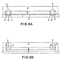
- Figure 6A is a cross sectional view of another embodiment of the present invention containing a channel adjacent to the edge region of the subpad wherein the subpad material is completely removed from the channel to form two subpad regions which protect the subpad against chemical mechanical slurry.
- Figure 6B is a cross sectional view of another embodiment of the present invention in which the subpad material is partially removed from the channel.
- Figs. 1 to 5 , 7 and 8 are cross sectional views illustrating further aspects of the present invention which can be used in combination with the measures shown in Figs. 6A and 6B .
- Figure 7 is a cross sectional view of another embodiment of the present invention comprising a subpad edge region which has been coated with a barrier agent to facilitate uniform distribution of the polishing layer and to prevent air bubbles from being trapped between the subpad surface and the polishing layer.
- Figure 8 is a cross sectional view of another embodiment of the present invention in which the polishing layer 3 encapsulates the subpad layer 2 on all sides, substantially sealing the subpad layer against chemical mechanical slurry penetration.
- the pads according to this invention can be used to polish any type of material or layer in any of various polishing steps, such as, for example, in semiconductor manufacturing.
- Typical materials to be polished include but are not limited to silicon, silicon dioxide, copper, tungsten, and aluminum.
- the polishing pad may be designed to selectively polish some materials and not others, to polish dissimilar materials at similar rates, or to work specifically with certain specific types of slurries and solutions.
- the pads of the present invention are especially suited for the chemical-mechanical polishing of electronic workpieces, such as silicon and semiconductor wafers, hard discs etc
- the pads and belts of the present invention may also be used to polish other substrates, for example for polishing and planarizing optical flats and mirrors
- the pad of the present may be applicable in other industries such as the pharmaceutical, chemical, and food industries.
- Figure 1 is a cross sectional depiction of the pad of the present invention.
- the pad includes a substrate 1 that serves as a support material, which in the case of the present embodiment is a stainless steel belt or belt made of other material (e.g., plastics, elastomers, etc.) with suitable mechanical strength or properties.
- the pad also includes a subpad layer 2, which is preferably compressible, and is attached to substrate 1 by means of an optional adhesive layer 4. Any suitable adhesive may be used to bond the subpad layer 2 to the optional substrate 1, such as a pressure sensitive adhesive.
- UHA 8791 sold by Avery Dennison Corporation (Pasadena, CA) may be used to adhere subpad 2 to substrate 1.
- the polishing pad of the present embodiment includes a polishing layer 3, comprising a polymer cast directly onto the subpad layer 2.
- substrate 1 because substrate 1, in operation, contacts the mechanical rollers that turn the belt, it is preferred that substrate 1 comprise a durable material such as stainless steel or other suitable material, with stainless steel being especially preferred.
- substrate 1 may comprise a woven metal mesh or perforate metal sheet, and the belt interstices maybe occupied by rivets or fillers of polymeric material to improve the bond strength between the polishing layer 3 and the substrate 1.
- the substrate 1 may be fully encapsulated by a polymer to avoid potential contamination or damage of the wafer during polishing. It should be noted that substrate 1 may itself comprise multiple layers.
- Substrate 1 is typically 1.5 - 4 meters in length (often between 1.5 and 3 meters), measured as the inner circumference of the belt loop, 0.1- 1.0 meters in width (often 0.2 - 0.6 meters), and.005-0.100 inches thick (with 0.010 - 0.030 inches being most preferred).
- An additional layer of protective material such as a polyethylene liner material, can be affixed to the inside surface of substrate 1, to protect substrate 1 and the hardware of the polishing apparatus.
- the subpad layer 2 may comprise any suitable material. Preferably, it comprises a compressible material that increases the ability of the pad to conform to the wafer surface during polishing. Suitable materials for subpad layer 2 are well known in the art, and include polymer foams and nonwoven materials made of any type of fiber, with or without fillers and impregnants. Subpad materials are typically compressible or exhibit relatively low hardness measurements (those falling within the Shore A hardness scale). Preferably, subpad layer 2 comprises a non-woven material, such as non-woven synthetic and natural fibers, including polyesters, polyamides, polyurethanes, polyolefins, fluoropolymers, cotton, wool, and combinations thereof.
- non-woven material such as non-woven synthetic and natural fibers, including polyesters, polyamides, polyurethanes, polyolefins, fluoropolymers, cotton, wool, and combinations thereof.
- subpad layer 2 a material suitable for use as subpad layer 2 is sold under the trade name SUBA IVTM by Rodel, Inc. (Newark, DE).
- Subpads having a textured, rather than smooth, surface topography may be used to maximize mechanical locking interactions.
- the outer layer of the subpad, including the subpad edges may include exposed fibers which increase the mechanical bonding between the subpad and polishing layer that is cast over the subpad.
- the surface of the subpad may be modified (e.g., by buffing, molding, embossing, cutting, scoring, etc.) to add texture that facilitates increased bonding.
- subpad layer 2 which may be one continuous piece or a combination of discontinuous segments, are shown in Fig. 1 in relative terms compared to the other elements of the belt.
- the width of subpad layer 2 is typically less than the width of substrate 1.
- the pad of Figure 1 is a continuous loop in the lengthwise direction, the length of subpad layer 2 (measured by its inner circumference) is substantially equal to the length of substrate 1 (measured by its outer circumference).
- the vertical edges of the subpad layer 2 are typically orthogonal to the horizontal surfaces of the subpad. Although that shape is not necessary, nor particularly preferred, such subpads are commercially available and simple to use.
- the polishing layer 3 comprises a mixture of one or more polymers cast over subpad layer 2.
- the polymer mixture preferably comprises polyurethane.
- the polishing layer can be solid or contains voids. Voids can be created by and suitable methods, such as by use of hollow microelements, by various foaming methods, or by sintering particles to form the polishing layer.
- Top layers can have any desired hardness. Different hardnesses are used to achieve different polishing performance and in different polishing applications. Commonly used top layers have hardness in the Shore D range. Most commonly in the 45-85 D range. More commonly in the 50-75D range.
- thermosettable polymer material including, but not limited to, a polyamide, a polyester, a polyacrylonitrile, a polyacrylate, a polymethacrylate, a polyvinylchloride, a polyvinyledene fluoride, a polytetrafluoroethylene, a polyethylene, a polypropylene and a polycarbonate.
- all polymerizable materials including thermoplastics, epoxies, silicone resins and rubbers could be used as well.
- Casting is the preferred method of coating subpad 2 with polishing layer 3 so as to create a seamless polishing layer that is resistant to delamination and impervious to the CMP slurry.
- Casting involves filling a mold with a hardenable fluid.
- the hardenable fluid comprises one or more reactive molecules (e.g., a prepolymer, monomer, resin, oligomer, etc.) and optionally one or more reaction initiators (e.g., polymerization initiator, curative, catalyst, hardener, etc.). Alternatively, the reaction may be initiated using light and/or heat.
- the reactive molecules and reaction initiator may optionally be dissolved in a suitable solvent.
- a hardenable fluid comprising one or more reactive molecules will often possess the desired flowability and coatability characteristics at the beginning of the reaction, as well as the desired solidity, durability, and seamlessness when fully reacted.
- the hardenable fluid may optionally comprise one or more non-reactive molecules.
- a polymer may be suspended or dissolved in a suitable solvent.
- the casting process results in a seamless polishing layer 3, which may be modified to provide optimum polishing performance.
- polishing layer 3 may comprise at least one layer of partially fused polymeric particles, or two or more thermoplastic polymers of different melting points. Abrasive particles or fibers may be added to polishing layer 3.
- the polishing surface may have micro or macro texturing, grooves, or discontinuities.
- It may have areas of hard and soft polymer, may have areas of transparent and opaque material, or may have areas of raised and lowered features. It may be formed with grooves (for example, extending in the running direction of the belt or across the width of the belt) to distribute and remove wet slurry and abraded particles generated during the polishing process and to reduce hydroplaning for more consistent contact between the polishing layer and the wafer. If desired slurry can be removed from the grooves using any suitable method, including but not limited to the use of one or more high pressure water jets, rotating fine brushes or hard non-metallic (e.g., ceramic) styli.
- any suitable method including but not limited to the use of one or more high pressure water jets, rotating fine brushes or hard non-metallic (e.g., ceramic) styli.
- the hardenable material is typically injected into the mold, containing subpad 2 and substrate 1, from an open top or through injection points at the bottom and/ or sides of the mold.
- a casting method is used wherein the hardenable fluid is applied uniformly to all areas of the subpad 2 and substrate 1.
- the properties (e.g., composition, temperature, etc.) of the hardenable fluid may be modified to ensure that its viscosity does not substantially rise during the period that it is applied to the subpad.
- the hardenable material will typically set-up into a solid in the hot mold in about 1-20 minutes.
- the casting is removed from the mold and sometimes placed on a retaining ring (to maintain its form) in an oven and fully cured for a prescribed time (typically 16-24 hours for urethanes) prior to being sent through secondary machining steps such as turning, grinding, grooving, end-point detection punching, and other trimming and laminating steps.
- the cast belts of the present invention differ significantly from prior art belts in which the polymer layer is coated onto the substrate by way of adhesion, lamination etc.
- casting permits the polishing layer 3 to combine with the substrate 1 and subpad 2 to create a continuous exterior surface of the polishing pad, completely encapsulating and substantially sealing subpad 3 against water penetration.
- the polishing layer is resistant to delamination to such a degree that it is not possible to peel away polishing layer 3 from the subpad 2 without destroying the integrity of the belt.
- Figure 1 is a cross-sectional view of a polishing pad in which a polyurethane material was cast directly on subpad 2. Consequently, the polyurethane polishing material 3 that was cast over subpad 2 encapsulates edge region 5 of the subpad, thereby providing an effective, robust, slurry-resistant seal that protects the subpad 2 from degradation by the CMP slurry. Moreover, the robust seal, formed by casting directly on the edge region 5 of the subpad, is able to withstand the bending and stretching associated with CMP polishing, and, in particular, LPT CMP polishing.
- Figure 2 shows a polishing belt comprising a substrate 1, compressible subpad 2, a polishing layer 3, and an optional adhesive layer 4 which binds the subpad 2 to substrate 1.
- the edges of the subpad of Figure 2 have been trimmed so that the thickness of the subpad is reduced around the edges.
- the edge region 5 of the subpad layer 2 can be modified by, e.g., cutting and removing its constituent material, prior to casting or a pre-modified subpad layer 2 can be obtained from another source and then casted upon with a polymer. Any amount of material may be removed, from substantially none to substantially all.
- the edge region 5 of subpad layer 2 and/or the contact portion of substrate 1 may simply be cut, scored and/or pierced.
- substantially all of the constituent material may be removed from edge region 5, leaving substantially no constituent material above optional adhesive layer 4.
- the constituent material may be removed in a substantially random manner, e.g., by using a dremel, providing no consistent shape to edge region 5, or the material may be systematically removed, e.g., by using a computer numerical control router, to provide a continuous, consistent shape to the subpad 2.
- the adhesive layer 4 and or subpad edge region 5 may contain partially embedded and partially exposed fibers 11 to mechanically lock with said polishing layer 3.
- Fig. 2 depicts edge region 5 to have substantially flat, orthogonal surfaces, no particular geometry of the edge region 5 must be achieved in order to improve the sealing performance of the encapsulated belt.
- the method of creating the edge region 5 typically involves cutting, scraping, and peeling of the subpad layer, precise geometries are potentially difficult to achieve.
- desirable adhesion and penetration of the polymer into the edge region 3 of subpad layer 2 may, in fact, be aided by an uneven surface texture of edge region 5.
- the reduction in thickness of the subpad edges facilitates the partial or complete penetration of the polyurethane into the subpad.
- the partial or complete saturation of the edges of the subpad with the polishing layer results in the complete encapsulation of the subpad edges by the polyurethane which substantially seals the subpad layer 2 against water and slurry penetration.
- the subpad edges are not exposed to the CMP slurry, and so cannot be attacked or degraded by CMP slurry.
- Figure 3 depicts another cross-sectional embodiment of the belt of the present invention.
- the substrate 1, the subpad layer 2, the polishing layer 3, and the optional adhesive layer 4 are as previously described, with the exception that the subpad layer 2 has an additional functional feature to promote the formation of a moisture-tight or watertight seal when a polymer is cast over the subpad layer 2.
- edge region 5 of the subpad layer 2 has a sloped structure, such that the thickness of edge region 5 decreases gradually from the interior region 7 outward to the perimeter edge.
- the increase in surface area of the sloped edge of subpad layer 2 in Fig. 3 as compared to a straight-edged subpad, provides a wider area of the subpad edge to which the polishing layer can bond during casting.
- Figure 3 depicts a subpad edge with a sloped structure, other shapes of edge region 5 can be used to increase the subpad edge surface area and improve the seal between the edge of the subpad and the polishing layer.
- the polishing layer 3 combines with subpad layer 2 to comprise a continuous exterior surface of the encapsulated belt which completely encapsulates and substantially seals the subpad edge region 5 against water penetration, preventing CMP slurry from contacting the subpad.
- the robust seal of the present invention protects the subpad edge region 5 from water and slurry penetration even in if the polishing layer 3 does not bond particularly well to the substrate 1. Consequently, the subpad cannot be attacked or degraded by CMP slurry.
- FIG. 4 Another embodiment of the encapsulated belts is shown, in cross section, in Figure 4 .
- the substrate 1, the subpad layer 2, the polishing layer 3, and the optional adhesive layer 4 are as previously described, with the exception that the subpad layer 2 has an additional functional feature to promote the formation of a watertight seal when the polymer mixture is cast over subpad layer 2.
- the edge region 5 of the subpad layer 2 is coated with an adhesive 12 or sealant prior to casting the polymer mixture over the subpad layer 2.
- Any suitable adhesive may be used, including, but not limited to, polyurethane based adhesives, acrylic based adhesives, methacrylic based adhesives, urethane based adhesives, cyanoacrylate based adhesives, vinylic based adhesives, epoxy based adhesives, styrenic based adhesives and rubber based adhesives, with polyurethane based and acrylic based adhesives being preferred.
- suitable polyurethane adhesives include D2596H Adhesive and D2597 Crosslinker, available from DELA, Inc. (Ward Hill, MA). Chemlok® 213, available from Lord® Corporation (Cary, NC) is an example of a suitable acrylic adhesive.
- the subpad layer 2 may be coated by one or more of a hot melt, contact cement, anaerobic compound, UV curative, emulsions (e.g., white glues), sealants (e.g., silicones, acrylics, urethanes, butyl and polysulfides), modified phenolic compounds, plastisols (e.g., modified PVC dispersions), polyvinyl acetates, and specialty adhesives (e.g., pressure sensitive, cohesive self-seal, heat seal, foam and fabric sealants).
- the adhesive or bonding compound may be applied in a suitable manner - e.g., by brushing, dipping, or spraying.
- Fig. 4 illustrates a subpad having vertical edge perpendicular to the horizontal surfaces of the subpad layer 2, any suitable edge region 5 geometry may be used (e.g., as described above in relation to Figs. 2 and 3 ).
- polishing layer 3 combines with subpad layer 2 to comprise a continuous exterior surface of the belt, which completely encapsulates and substantially seals the edges of the subpad against water penetration, preventing CMP slurry from contacting the subpad and causing degradation.
- the robust seal of the present invention protects the subpad edge region 5 from water and slurry penetration even in if the polishing layer 3 does not bond particularly well to the substrate 1. Consequently, the subpad cannot be attacked or degraded by CMP slurry.
- edge region 5 of the subpad layer 2 can be modified by, e.g., cutting and removing constituent material, and then coating it with adhesive 12 prior to casting.
- a pre-modified subpad layer 2 can be obtained from another source, and then coated with adhesive 12 prior to casting.
- Figure 5 depicts, in cross section, another embodiment of the present invention.
- the substrate 1, the subpad layer 2, the polishing layer 3, and the optional adhesive layer 4 are as previously described, with the exception that the subpad layer 2 has an additional functional feature to promote the formation of a watertight seal when the polishing layer 3 is cast over subpad layer 2.
- each edge region 5 of the subpad layer is heat sealed or pressure embossed to promote the formation of a watertight seal when the polymer mixture is cast onto the subpad layer 2.
- the edge region 5 of the subpad layer 2 can be heat sealed prior to casting, or a pre-modified (i.e., already heat-sealed) subpad layer 2 can be obtained from another source and then cast over with a polymer.
- the seal may be formed in edge region 5 directly on the perimeter edge of subpad layer 2.
- the seal may be placed in edge region 5 inward from the perimeter edge of subpad layer 2 by applying a custom heat sealer or rotary heat sealer to the subpad at a suitable distance from the edge region.
- a seal having a width of about 0.05 - 0.5 inches (preferably 0.25 inches) could be placed about 0.1 to 1 inch inward from the perimeter edge of the subpad layer 2.
- the polishing layer 3 combines with the subpad layer 2 to comprise a continuous exterior surface of the encapsulated belt, which completely encapsulates and substantially seals the subpad edge against water penetration, preventing CMP slurry from contacting the subpad and degrading the belt.
- the robust seal of the present invention protects the subpad edge region 5 from water and slurry penetration even in if the polishing layer 3 does not bond particularly well to the substrate 1. Consequently, the subpad cannot be attacked or degraded by CMP slurry.
- each edge region 5 of the subpad layer 2 comprises a channel 10 running adjacent to the perimeter edge of subpad layer 2, wherein the subpad material completely removed from the channel 10 to form two subpad regions.
- the outer subpad region 8 borders the inner subpad region 9 at a distance.
- the outer region 8 forms a barrier for the inner subpad region 9 and protects the inner subpad region 9, as well as the entire subpad layer 2, from any CMP slurry that penetrates the outer polishing layer 3 that is cast over the subpad 2.
- the subpad region 8, which is encapsulated by polishing layer 3, would serve as a first defense against the slurry.
- the slurry is not likely to penetrate the inner subpad region 9, even if the polishing layer surrounding subpad region 9 contains imperfections, since the imperfections in the polishing layer encapsulating inner subpad region 9 are not likely to be positioned parallel to the imperfection in the polishing layer encapsulating outer subpad region 8.
- the driving force of the slurry as it approaches inner subpad region 9 will be much lower.
- the channel can have any suitable dimensions, e.g., width and depth, and can be any suitable shape.
- any cross sectional shape may be used, such as, for example, circular, pyramidal (vertical or inverted), "L” shaped, inverted “T” shaped, etc.
- each edge region 5 of the subpad layer 2 comprises a channel 10 running adjacent to the perimeter edge of subpad layer 2, wherein the subpad material is partially removed from the channel 10 to form two subpad regions which appear as inner subpad region 9 and outer subpad region 8.
- the subpad material of the channel 10 is thinner than inner subpad region 9 and outer subpad region 8.
- the channel of Figure 6B can have any suitable dimension (e.g., width and depth), can be any suitable shape, and can extend any suitable distance from the perimeter edge of inner subpad region 2.
- a separate strip of material i.e., a material other than the subpad material or a different subpad material is placed adjacent the subpad to create a second barrier.
- each channel be of such dimensions that it creates an effective barrier against slurry seeping into subpad layer 2, without interfering with the cushioning performance of subpad layer 2 in the polishing region of the encapsulated belt.
- channels do not necessarily need to go substantially to the substrate to be effective. It is possible to create an effective channel by only removing a portion of the substrate only, or all of subpad material but not the adhesive, or alternatively by removing all of the subpad material and a portion of the adhesive.
- the channel can be created in any suitable manner. For example, two incisions can be made into the edge region 5 about 0.1 to 1 inch (preferably 0.25 inches) inward from the perimeter edge of the subpad layer 2, having a width of about 0.05 to 0.5 inches (preferably 0.25 inches) and a depth that substantially or partially reaches down to the substrate 1. Furthermore, the channel can be cut into each edge region 5 of the subpad layer 2 prior to casting, or a pre-modified subpad layer 2 (i.e., already comprising channels in each edge region 5) can be obtained from another source and then cast over with a polymer mixture.
- a pre-modified subpad layer 2 i.e., already comprising channels in each edge region 5
- the polishing layer 3 combines with subpad layer 2 to comprise a continuous exterior surface of the encapsulated belt, which completely encapsulates and substantially seals the subpad edges against water or slurry penetration, preventing CMP slurry from contacting the subpad and degrading the belt.
- the subpad layer 2 may comprise any of the previously-described additional functional features to promote the formation of a watertight seal when the polishing layer 3 is cast upon the subpad layer 2.
- Figure 7 illustrates this embodiment
- the substrate 1, the subpad layer 2, the polishing layer 3, and the optional adhesive layer 4 are as previously described.
- the belt of Figure 7 additionally comprises element 18, a barrier agent disposed on the outer surface of the subpad layer 2, including the edges of the subpad, which promotes the uniform distribution of the polishing layer 3 when cast thereon.
- the barrier agent 18 typically comprises a material whose viscosity increases after it is applied to the subpad 2.
- barrier agent 18 any material having the following properties, when applied to the subpad 2, may be used as barrier agent 18: (a) the barrier agent should adhere strongly to both subpad 2 and polishing layer 3; (b) it should substantially prevent polishing layer 3 from penetrating past it into the subpad; and (c) it should not substantially alter the compressibility of the subpad.
- barrier agent 18 be capable of adhering to subpad 2 and to polishing layer 3 via chemical adhesive forces and/or mechanical locking interactions, in order to promote strong adhesion between the elements of the polishing pad.
- the barrier agent's chemical adhesive forces will vary depending on the composition of subpad 2 and polishing layer 3.
- Materials capable of strong adhesion to the various components of subpad 2 and polishing layer 3 are well known to those of skill in the art and may include a polyurethane, acrylic, methacrylic, urethane, cyanoacrylate, vinylic, epoxy, or styrenic based adhesive.
- hot melts contact cements, anaerobics (acrylics), UV curables, emulsions (white glues), sealants (silicones, acrylics, urethanes, butyl and polysulfides, etc.), modified phenolics, plastisols (modified PVC dispersions), rubber adhesives (solution, latexes), polyvinyl acetates (emulsions), specialty adhesives (pressure sensitive, cohesive self-seal, heat seal, foam & fabric, etc.), and labeling adhesives (resin adhesives, latex adhesives, etc.). Polyurethane and acrylic adhesives are preferred.
- barrier agent 18 comprises a material that is fluid enough to fill the lowermost textured portions of subpad 2 when it is applied, but viscous enough to adopt the texture of subpad 2. That combination of properties can be found in materials, such as hardenable fluids, which can be applied at relatively low viscosities, but which increase in viscosity rapidly after application. Adhesives that increase in viscosity after application, such as adhesives applied in volatile solvents, are suitably used as barrier agent 18. Examples include polyurethane adhesives, such as D2596H Adhesive and D2597 Crosslinker, available from DELA, Inc. (Ward Hill, MA), and acrylic adhesives, such as Chenllok® 213, available from Lord® Corporation (Cary, NC). Alternatively or additionally, the surface of barrier agent 18 may be modified to add texture.
- barrier agent 18 that can chemically bond to polishing layer 3.
- barrier agent 18 and the hardenable fluid that will create polishing layer 3 initially comprise reactive molecules, then cross-reaction between the elements will be possible if the hardenable fluid is coated onto barrier agent 18 before the latter has fully reacted.
- the barrier agent 18 can be applied to the edges of the subpad layer 2 using any suitable method, such as brushing, blowing, dipping, spraying, knifing, and transfer coating. Any suitable amount of barrier agent may be used.
- the subpad can be subjected to secondary processing such as sanding, embossing, and maching to achieve desired texture, grooves or patterns on the subpad.
- subpad layer 2 can be coated with barrier agent 18 prior to casting.
- the subpad layer 2 may include one or more additional functional features to promote the formation of a watertight seal the polishing layer 3.
- the edge region 5 of the subpad layer 2 and/or the contact portion of substrate may be modified, as previously described (e.g., by cutting, scoring, piercing, channeling the edge region of the subpad layer), either before or after subpad layer 2 is coated with barrier agent 18.
- a pre-modified subpad layer 2 containing the barrier agent 18 may be obtained and cast upon.
- Figure 8 illustrates, in cross section, another embodiment of the encapsulated belt and encapsulated pad.
- a substrate element (element 1 in previous Figures) does not combine with the polishing layer 3 to comprise a continuous exterior surface of the encapsulated belt which substantially seals the subpad layer 2 against water penetration.
- the polishing layer 3 alone encapsulates the subpad layer 2, substantially sealing subpad layer 2 against water penetration.
- the subpad is not exposed to the CMP slurry, and so, cannot be attacked or degraded by CMP slurry.
- Subpad layer 2 is not placed onto substrate 1 prior to casting a polymer mixture thereover. Instead, either of two methods may be used. In one method, a first polymer mixture may be cast in a mold to form a first layer. Then, preferably before the first layer cures, subpad layer 2 is placed onto the first layer. Finally, preferably before the first layer cures, a second polymer mixture (which may be identical to the first) is cast over the subpad layer 2, being careful to completely cover all exposed surfaces of subpad layer 2. The first and second polymer mixtures combine to completely encapsulate and substantially seal the subpad layer 2 against water penetration.
- a polymer mixture may be cast to cover all surfaces of subpad layer 2, to completely encapsulate and substantially seal the subpad layer 2 against water penetration.
- the encapsulated subpad layer 2 may then be optionally attached to a substrate 1, for example using an adhesive layer 4.
- a belt may contain a polishing layer, subpad layer and substrate layer with adjacent overlapping apertures for purposes of endpoint detection.
- the aperture runs from the polishing surface, through the subpad and through the substrate on the opposite side of the polishing surface to allow a light beam to pass from a monitor located below the substrate to the wafer positioned above the polishing surface. Consequently, the periphery of the aperture in the subpad is exposed to the chemical slurry or water that is applied to the surface of the pad.
- the chemical slurry can enter the subpad by way of the peripheral edge of the aperture and degrade the belt just as if it had entered the outer edge regions of the subpad.
- the present invention overcomes this problem in the same manner as discussed above with respect to the outer subpad edge - i.e., by cutting, scoring, piercing, channeling, heat-sealing, applying adhesives and casting over the peripheral edges of the subpad aperture.
Landscapes
- Engineering & Computer Science (AREA)
- Mechanical Engineering (AREA)
- Mechanical Treatment Of Semiconductor (AREA)
- Finish Polishing, Edge Sharpening, And Grinding By Specific Grinding Devices (AREA)
- Laminated Bodies (AREA)
Claims (17)
- Band oder Pad zum Polieren oder Ebnen eines Werkstücks, versehen mit einem Substrat (1), einer saumlosen Polierlage (3) und mindestens einer Subpad-Lage (2), die zwischen dem Substrat und der Polierlage angeordnet ist, wobei das Subpad einen inneren Bereich (7) und mindestens einen Randbereich (5), der am Umfangsrand der Subpad-Lage angeordnet ist, aufweist, wobei der Randbereich einen Kanal aufweist, der benachbart dem Umfangsrand der Subpad-Lage verläuft, und wobei die Polierlage (3) über das Subpad (2) und das Substrat (1) gegossen ist, um die Subpad-Lage zu verkapseln und Feuchtigkeit im Wesentlichen daran zu hindern, in die Subpad-Lage (2) einzudringen.
- Band oder Pad gemäß Anspruch 1, wobei die Subpad-Lage (2) ein kompressibles, nicht gewebtes Material aufweist.
- Band oder Pad gemäß Anspruch 1 oder 2, wobei das Substrat (1) rostfreien Stahl, Kunststoff oder ein Elastomer aufweist.
- Band oder Pad gemäß einem der vorhergehenden Ansprüche, bei welchem mindestens der Randbereich (5) der Subpad-Lage mit einem Sperrmittel (18) beschichtet ist, um eine gleichmäßige Verteilung der Polierlage (3) zu erleichtern.
- Band oder Pad gemäß Anspruch 1, wobei die Polierlage (3) aus einem polymerisierbaren Werkstoff gefertigt ist, wobei der Randbereich (5) der Subpad-Lage (2) ein oder mehrere funktionelle Merkmale aufweist, welche die Bildung einer feuchtigkeitsbeständigen Dichtung fördern.
- Band oder Pad gemäß Anspruch 5, wobei die Subpad-Lage (2) ein komprimierbares, nicht gewebtes Material aufweist.
- Band oder Pad gemäß Anspruch 5 oder 6, wobei der polymerisierbare Werkstoff mindestens einen der folgenden Werkstoffe aufweist: ein Polyurethan, Polyamid, ein Polyester, ein Polyacrylonitril, ein Polyacrylat, ein Polymethacrylat, ein Polyvinylchlorid, ein Polyvinylidenfluorid, ein Polytetrafluorethylen, ein Polyethylen, ein Polypropylen, ein Polycarbonat, einen thermoplastischen Werkstoff, ein Epoxid, ein Silikonharz und ein natürlicher oder synthetischer Gummiwerkstoff.
- Band oder Pad gemäß einem der Ansprüche 5 bis 7, wobei der Randbereich (5) der Subpad-Lage mit einem Klebstoff (4) beschichtet ist.
- Band oder Pad gemäß Anspruch 8, wobei der Klebstoff (4) ein Klebstoff auf Polyurethanbasis ist, der in die Subpad-Lage (2) eindringt.
- Band oder Pad gemäß einem der Ansprüche 5 bis 7, wobei mindestens der Randbereich (5) der Subpad-Lage (2) mit einem Sperrmittel (18) beschichtet ist, um ein gleichförmiges Durchdringen mit der Polierlage (3) zu erleichtern.
- Band oder Pad gemäß Anspruch 1 zum chemisch-mechanischen Polieren eines elektronischen Werkstücks, versehen mit einer robusten Dichtung zwischen der Polierlage (3) und mindestens einem Randbereich (5) einer kompressiblen Subpad-Lage, der an einem Umfangsrand eines kompressiblen Subpads (2) angeordnet ist, wobei die Polierlage (3) über das Subpad (2) gegossen ist, um das Subpad (2) zu verkapseln, und den Randbereich (5) der Subpad-Lage gegen ein chemischmechanisches Eindringen einer Aufschlämmung abzudichten.
- Band oder Pad gemäß Anspruch 11, wobei die Subpad-Lage (2) ein kompressibles, nicht gewebtes Material aufweist.
- Band oder Pad gemäß Anspruch 11, wobei der Randbereich (5) mit einem Klebstoff beschichtet ist.
- Band oder Pad gemäß Anspruch 11, versehen mit einem Substrat (1), wobei die Polierlage (3) über das Subpad (2) gegossen ist, um sich mit dem Substrat zu verbinden, um die Subpad-Lage (2) zu verkapseln und abzudichten.
- Verfahren zur Herstellung eines verkapselten Bands oder Pads zum Polieren oder Ebnen eines Werkstücks mit den Schritten:Bereitstellen eines Substrats (1) mit einem Kontaktbereich,Platzieren einer Subpad-Lage (2) auf das Substrat (1), wobei die Subpad-Lage (2) einen inneren Bereich (7) und mindestens einen Randbereich (5), der entlang dem Umfang der Subpad-Lage (2) angeordnet ist, aufweist,Modifizieren mindestens des Randbereichs (5) der Subpad-Lage (2) durch Ausbilden eines Kanals (10) in dem mindestens einen Randbereich (5) der Subpad-Lage (2), in dem eine Menge an Material der Subpad-Lage von dem Randbereich entfernt wird, um die Ausbildung einer wasserdichten und aufschlämmungsbeständigen Dichtung zu fordern, wenn eine Polierlage über das Subpad gegossen wird, undGießen einer Polierlage (3), die ein polymerisierbares Material aufweist, über die Subpad-Lage (2), so dass die Polierlage (3) an dem Kontaktbereich des Substrats (1) mit dem Substrat (1) in Kontakt tritt, um die Subpad-Lage (2) zu verkapseln.
- Verfahren gemäß Anspruch 15, wobei der Modifikationsschritt zusätzlich das Aufbringen eines Klebstoffs (4) auf den Randbereich (5) der Subpad-Lage (2) umfasst.
- Verfahren gemäß Anspruch 15, bei welchem der Modifikationsschritt zusätzlich das Aufbringen eines Sperrmittels (10) auf den Randbereich (5) der Subpad-Lage (2) umfasst.
Applications Claiming Priority (5)
| Application Number | Priority Date | Filing Date | Title |
|---|---|---|---|
| US38694302P | 2002-06-07 | 2002-06-07 | |
| US386943P | 2002-06-07 | ||
| US273194 | 2002-10-16 | ||
| US10/273,194 US7201647B2 (en) | 2002-06-07 | 2002-10-16 | Subpad having robust, sealed edges |
| PCT/US2003/018199 WO2003105191A2 (en) | 2002-06-07 | 2003-06-09 | Subpad having robust, sealed edges |
Publications (3)
| Publication Number | Publication Date |
|---|---|
| EP1512168A2 EP1512168A2 (de) | 2005-03-09 |
| EP1512168A4 EP1512168A4 (de) | 2008-07-23 |
| EP1512168B1 true EP1512168B1 (de) | 2010-06-02 |
Family
ID=29714926
Family Applications (1)
| Application Number | Title | Priority Date | Filing Date |
|---|---|---|---|
| EP03736966A Expired - Lifetime EP1512168B1 (de) | 2002-06-07 | 2003-06-09 | Subpad mit robusten, versiegelten rändern |
Country Status (9)
| Country | Link |
|---|---|
| US (1) | US7201647B2 (de) |
| EP (1) | EP1512168B1 (de) |
| JP (1) | JP4445383B2 (de) |
| KR (2) | KR101027190B1 (de) |
| CN (1) | CN100467215C (de) |
| AU (2) | AU2003237519A1 (de) |
| DE (1) | DE60332832D1 (de) |
| TW (1) | TWI301784B (de) |
| WO (1) | WO2003105191A2 (de) |
Families Citing this family (25)
| Publication number | Priority date | Publication date | Assignee | Title |
|---|---|---|---|---|
| US20040102140A1 (en) * | 2002-11-21 | 2004-05-27 | Wood Jeffrey H. | Contour following end effectors for lapping/polishing |
| US20070015448A1 (en) * | 2003-08-07 | 2007-01-18 | Ppg Industries Ohio, Inc. | Polishing pad having edge surface treatment |
| JP4965253B2 (ja) * | 2003-08-08 | 2012-07-04 | インテグリス・インコーポレーテッド | 回転可能ベース上に鋳造されるモノリシック多孔性パッドを作製する方法および材料 |
| US6921324B1 (en) * | 2004-08-05 | 2005-07-26 | United Microelectronics Corp. | Pad backer |
| US7048615B2 (en) * | 2004-08-05 | 2006-05-23 | United Microelectronics Corp. | Pad backer and CMP process using the same |
| JP2006068869A (ja) * | 2004-09-03 | 2006-03-16 | Inoac Corp | 研磨パッド |
| US20060089095A1 (en) | 2004-10-27 | 2006-04-27 | Swisher Robert G | Polyurethane urea polishing pad |
| KR100785604B1 (ko) * | 2006-12-11 | 2007-12-14 | 동부일렉트로닉스 주식회사 | 방수 수지코팅 처리한 폴리싱 패드 |
| US8083570B2 (en) * | 2008-10-17 | 2011-12-27 | Rohm And Haas Electronic Materials Cmp Holdings, Inc. | Chemical mechanical polishing pad having sealed window |
| US8652225B2 (en) * | 2009-07-27 | 2014-02-18 | Joseph H. MacKay | Flexible coated abrasive finishing article and method of manufacturing the same |
| US8491808B2 (en) * | 2010-03-16 | 2013-07-23 | Rohm And Haas Electronic Materials Cmp Holdings, Inc. | Method of polishing a substrate comprising polysilicon, silicon oxide and silicon nitride |
| US8492277B2 (en) * | 2010-03-16 | 2013-07-23 | Rohm And Haas Electronic Materials Cmp Holdings, Inc | Method of polishing a substrate comprising polysilicon and at least one of silicon oxide and silicon nitride |
| US8496843B2 (en) * | 2010-03-16 | 2013-07-30 | Rohm And Haas Electronic Materials Cmp Holdings, Inc. | Method of polishing a substrate comprising polysilicon and at least one of silicon oxide and silicon nitride |
| US20120302148A1 (en) | 2011-05-23 | 2012-11-29 | Rajeev Bajaj | Polishing pad with homogeneous body having discrete protrusions thereon |
| US9067298B2 (en) | 2011-11-29 | 2015-06-30 | Nexplanar Corporation | Polishing pad with grooved foundation layer and polishing surface layer |
| US9067297B2 (en) * | 2011-11-29 | 2015-06-30 | Nexplanar Corporation | Polishing pad with foundation layer and polishing surface layer |
| US9597769B2 (en) | 2012-06-04 | 2017-03-21 | Nexplanar Corporation | Polishing pad with polishing surface layer having an aperture or opening above a transparent foundation layer |
| TWI769988B (zh) * | 2015-10-07 | 2022-07-11 | 美商3M新設資產公司 | 拋光墊與系統及其製造與使用方法 |
| KR102318972B1 (ko) * | 2017-03-28 | 2021-11-02 | 주식회사 케이씨텍 | 기판 연마 장치 |
| KR102591901B1 (ko) * | 2017-10-31 | 2023-10-20 | 가부시키가이샤 에바라 세이사꾸쇼 | 연마 패드의 연마면의 온도를 조정하기 위한 열교환기, 해당 열교환기를 구비한 연마 장치, 해당 열교환기를 사용한 기판의 연마 방법 및 연마 패드의 연마면의 온도를 조정하기 위한 프로그램을 기록한 컴퓨터 판독 가능한 기록 매체 |
| JP7059117B2 (ja) * | 2017-10-31 | 2022-04-25 | 株式会社荏原製作所 | 研磨パッドの研磨面の温度を調整するための熱交換器、該熱交換器を備えた研磨装置、該熱交換器を用いた基板の研磨方法、および研磨パッドの研磨面の温度を調整するためのプログラムを記録したコンピュータ読み取り可能な記録媒体 |
| JP7026943B2 (ja) * | 2018-05-08 | 2022-03-01 | 丸石産業株式会社 | 研磨パッド及び該研磨パッドによる研磨方法 |
| CN108972381A (zh) * | 2018-07-26 | 2018-12-11 | 成都时代立夫科技有限公司 | 一种cmp抛光垫封边工艺 |
| CN115397614B (zh) * | 2020-03-26 | 2024-08-23 | 富士纺控股株式会社 | 抛光垫、抛光单元、抛光装置、及抛光垫的制造方法 |
| TWI812936B (zh) | 2021-04-01 | 2023-08-21 | 智勝科技股份有限公司 | 研磨墊及研磨方法 |
Family Cites Families (16)
| Publication number | Priority date | Publication date | Assignee | Title |
|---|---|---|---|---|
| US5310455A (en) * | 1992-07-10 | 1994-05-10 | Lsi Logic Corporation | Techniques for assembling polishing pads for chemi-mechanical polishing of silicon wafers |
| JP3329644B2 (ja) * | 1995-07-21 | 2002-09-30 | 株式会社東芝 | 研磨パッド、研磨装置及び研磨方法 |
| JPH10249709A (ja) * | 1997-03-14 | 1998-09-22 | Chiyoda Kk | 研磨布 |
| US6126532A (en) * | 1997-04-18 | 2000-10-03 | Cabot Corporation | Polishing pads for a semiconductor substrate |
| JP2842865B1 (ja) * | 1997-08-22 | 1999-01-06 | 九州日本電気株式会社 | 研磨装置 |
| US6491570B1 (en) * | 1999-02-25 | 2002-12-10 | Applied Materials, Inc. | Polishing media stabilizer |
| EP1052059A3 (de) * | 1999-05-03 | 2001-01-24 | Applied Materials, Inc. | Verfahren zum chemisch-mechanisch Planarisieren |
| US6439968B1 (en) | 1999-06-30 | 2002-08-27 | Agere Systems Guardian Corp. | Polishing pad having a water-repellant film theron and a method of manufacture therefor |
| US6244944B1 (en) * | 1999-08-31 | 2001-06-12 | Micron Technology, Inc. | Method and apparatus for supporting and cleaning a polishing pad for chemical-mechanical planarization of microelectronic substrates |
| US6464576B1 (en) | 1999-08-31 | 2002-10-15 | Rodel Holdings Inc. | Stacked polishing pad having sealed edge |
| US6733373B1 (en) * | 2000-03-31 | 2004-05-11 | Taiwan Semiconductor Manufacturing Co., Ltd. | Polishing assembly for a linear chemical mechanical polishing apparatus and method for forming |
| WO2001083167A1 (en) | 2000-05-03 | 2001-11-08 | Rodel Holdings, Inc. | Polishing pad with a seam which is reinforced with caulking material |
| JP4686010B2 (ja) * | 2000-07-18 | 2011-05-18 | ニッタ・ハース株式会社 | 研磨パッド |
| US6485359B1 (en) * | 2000-09-15 | 2002-11-26 | Applied Materials, Inc. | Platen arrangement for a chemical-mechanical planarization apparatus |
| US6561889B1 (en) * | 2000-12-27 | 2003-05-13 | Lam Research Corporation | Methods for making reinforced wafer polishing pads and apparatuses implementing the same |
| US6613200B2 (en) * | 2001-01-26 | 2003-09-02 | Applied Materials, Inc. | Electro-chemical plating with reduced thickness and integration with chemical mechanical polisher into a single platform |
-
2002
- 2002-10-16 US US10/273,194 patent/US7201647B2/en not_active Expired - Lifetime
-
2003
- 2003-06-09 AU AU2003237519A patent/AU2003237519A1/en not_active Abandoned
- 2003-06-09 WO PCT/US2003/018199 patent/WO2003105191A2/en not_active Ceased
- 2003-06-09 JP JP2004512169A patent/JP4445383B2/ja not_active Expired - Lifetime
- 2003-06-09 EP EP03736966A patent/EP1512168B1/de not_active Expired - Lifetime
- 2003-06-09 AU AU2003238941A patent/AU2003238941A1/en not_active Abandoned
- 2003-06-09 DE DE60332832T patent/DE60332832D1/de not_active Expired - Lifetime
- 2003-06-09 KR KR1020047019798A patent/KR101027190B1/ko not_active Expired - Lifetime
- 2003-06-09 CN CNB038191008A patent/CN100467215C/zh not_active Expired - Lifetime
- 2003-06-09 KR KR1020047019895A patent/KR101099886B1/ko not_active Expired - Lifetime
- 2003-06-10 TW TW092115741A patent/TWI301784B/zh not_active IP Right Cessation
Also Published As
| Publication number | Publication date |
|---|---|
| WO2003105191A2 (en) | 2003-12-18 |
| CN100467215C (zh) | 2009-03-11 |
| KR101099886B1 (ko) | 2011-12-28 |
| CN1675027A (zh) | 2005-09-28 |
| TWI301784B (en) | 2008-10-11 |
| US7201647B2 (en) | 2007-04-10 |
| JP4445383B2 (ja) | 2010-04-07 |
| AU2003237519A8 (en) | 2003-12-22 |
| WO2003105191A3 (en) | 2004-08-26 |
| TW200406287A (en) | 2004-05-01 |
| US20030228836A1 (en) | 2003-12-11 |
| KR101027190B1 (ko) | 2011-04-06 |
| JP2006509349A (ja) | 2006-03-16 |
| AU2003237519A1 (en) | 2003-12-22 |
| KR20040111724A (ko) | 2004-12-31 |
| KR20050020824A (ko) | 2005-03-04 |
| AU2003238941A1 (en) | 2003-12-22 |
| DE60332832D1 (de) | 2010-07-15 |
| EP1512168A2 (de) | 2005-03-09 |
| EP1512168A4 (de) | 2008-07-23 |
Similar Documents
| Publication | Publication Date | Title |
|---|---|---|
| EP1512168B1 (de) | Subpad mit robusten, versiegelten rändern | |
| US6561889B1 (en) | Methods for making reinforced wafer polishing pads and apparatuses implementing the same | |
| CN101107095B (zh) | 用于低压研磨的多层研磨垫 | |
| US6572463B1 (en) | Methods for making reinforced wafer polishing pads utilizing direct casting and apparatuses implementing the same | |
| KR100882045B1 (ko) | 그루브형 서브패드를 구비한 폴리싱 장치 | |
| KR100770852B1 (ko) | 화학 기계적 평탄화용 그루브형 연마 패드 | |
| US8287793B2 (en) | Methods for producing in-situ grooves in chemical mechanical planarization (CMP) pads, and novel CMP pad designs | |
| CN100445091C (zh) | 控制渗透子垫 | |
| US20040248508A1 (en) | Controlled penetration subpad | |
| KR100394572B1 (ko) | 복합특성을 가지는 씨엠피 패드구조와 그 제조방법 | |
| US7621798B1 (en) | Reducing polishing pad deformation | |
| KR20100043024A (ko) | 밀봉된 창을 갖는 화학 기계 연마 패드 | |
| US7160181B2 (en) | Polishing pad of CMP equipment for polishing a semiconductor wafer | |
| EP1345733B1 (de) | Verfahren zur herstellung von verstärkten waferpolierkissen und diese verfahren implementierende vorrichtungen | |
| EP3887093A1 (de) | Polierpads sowie systeme und verfahren zur herstellung und verwendung davon | |
| US8303382B2 (en) | Polishing pad and method of fabrication | |
| JP7220130B2 (ja) | 研磨パッド及び研磨パッドの製造方法 | |
| JP4362443B2 (ja) | 侵入調節サブパッド | |
| JP5033357B2 (ja) | 研磨パッド | |
| JP5033356B2 (ja) | 研磨パッド | |
| JP5022635B2 (ja) | 研磨パッド |
Legal Events
| Date | Code | Title | Description |
|---|---|---|---|
| PUAI | Public reference made under article 153(3) epc to a published international application that has entered the european phase |
Free format text: ORIGINAL CODE: 0009012 |
|
| 17P | Request for examination filed |
Effective date: 20041206 |
|
| AK | Designated contracting states |
Kind code of ref document: A2 Designated state(s): AT BE BG CH CY CZ DE DK EE ES FI FR GB GR HU IE IT LI LU MC NL PT RO SE SI SK TR |
|
| AX | Request for extension of the european patent |
Extension state: AL LT LV MK |
|
| DAX | Request for extension of the european patent (deleted) | ||
| RBV | Designated contracting states (corrected) |
Designated state(s): DE FR GB IE IT |
|
| RIN1 | Information on inventor provided before grant (corrected) |
Inventor name: CIANCIOLO, JOSEPH Inventor name: LOMBARDO, BRIAN, SCOTT |
|
| A4 | Supplementary search report drawn up and despatched |
Effective date: 20080620 |
|
| RIC1 | Information provided on ipc code assigned before grant |
Ipc: B24D 15/00 20060101ALI20080724BHEP Ipc: B24B 5/00 20060101ALI20080724BHEP Ipc: B24B 1/00 20060101AFI20080724BHEP |
|
| 17Q | First examination report despatched |
Effective date: 20081126 |
|
| GRAP | Despatch of communication of intention to grant a patent |
Free format text: ORIGINAL CODE: EPIDOSNIGR1 |
|
| GRAS | Grant fee paid |
Free format text: ORIGINAL CODE: EPIDOSNIGR3 |
|
| GRAA | (expected) grant |
Free format text: ORIGINAL CODE: 0009210 |
|
| AK | Designated contracting states |
Kind code of ref document: B1 Designated state(s): DE FR GB IE IT |
|
| REG | Reference to a national code |
Ref country code: GB Ref legal event code: FG4D |
|
| REG | Reference to a national code |
Ref country code: IE Ref legal event code: FG4D |
|
| REF | Corresponds to: |
Ref document number: 60332832 Country of ref document: DE Date of ref document: 20100715 Kind code of ref document: P |
|
| PLBE | No opposition filed within time limit |
Free format text: ORIGINAL CODE: 0009261 |
|
| STAA | Information on the status of an ep patent application or granted ep patent |
Free format text: STATUS: NO OPPOSITION FILED WITHIN TIME LIMIT |
|
| 26N | No opposition filed |
Effective date: 20110303 |
|
| REG | Reference to a national code |
Ref country code: DE Ref legal event code: R097 Ref document number: 60332832 Country of ref document: DE Effective date: 20110302 |
|
| PGFP | Annual fee paid to national office [announced via postgrant information from national office to epo] |
Ref country code: IE Payment date: 20110627 Year of fee payment: 9 |
|
| REG | Reference to a national code |
Ref country code: IE Ref legal event code: MM4A |
|
| PG25 | Lapsed in a contracting state [announced via postgrant information from national office to epo] |
Ref country code: IE Free format text: LAPSE BECAUSE OF NON-PAYMENT OF DUE FEES Effective date: 20120609 |
|
| REG | Reference to a national code |
Ref country code: FR Ref legal event code: PLFP Year of fee payment: 14 |
|
| REG | Reference to a national code |
Ref country code: FR Ref legal event code: PLFP Year of fee payment: 15 |
|
| REG | Reference to a national code |
Ref country code: FR Ref legal event code: PLFP Year of fee payment: 16 |
|
| PGFP | Annual fee paid to national office [announced via postgrant information from national office to epo] |
Ref country code: IT Payment date: 20180919 Year of fee payment: 14 |
|
| PG25 | Lapsed in a contracting state [announced via postgrant information from national office to epo] |
Ref country code: IT Free format text: LAPSE BECAUSE OF NON-PAYMENT OF DUE FEES Effective date: 20190609 |
|
| PGFP | Annual fee paid to national office [announced via postgrant information from national office to epo] |
Ref country code: GB Payment date: 20220506 Year of fee payment: 20 Ref country code: FR Payment date: 20220510 Year of fee payment: 20 Ref country code: DE Payment date: 20220505 Year of fee payment: 20 |
|
| REG | Reference to a national code |
Ref country code: DE Ref legal event code: R071 Ref document number: 60332832 Country of ref document: DE |
|
| REG | Reference to a national code |
Ref country code: GB Ref legal event code: PE20 Expiry date: 20230608 |
|
| PG25 | Lapsed in a contracting state [announced via postgrant information from national office to epo] |
Ref country code: GB Free format text: LAPSE BECAUSE OF EXPIRATION OF PROTECTION Effective date: 20230608 |