EP1511682B1 - Stapelfach für flache sendungen - Google Patents
Stapelfach für flache sendungen Download PDFInfo
- Publication number
- EP1511682B1 EP1511682B1 EP03735296A EP03735296A EP1511682B1 EP 1511682 B1 EP1511682 B1 EP 1511682B1 EP 03735296 A EP03735296 A EP 03735296A EP 03735296 A EP03735296 A EP 03735296A EP 1511682 B1 EP1511682 B1 EP 1511682B1
- Authority
- EP
- European Patent Office
- Prior art keywords
- pile
- support
- stack
- stacking
- compartment
- Prior art date
- Legal status (The legal status is an assumption and is not a legal conclusion. Google has not performed a legal analysis and makes no representation as to the accuracy of the status listed.)
- Expired - Lifetime
Links
- 238000011144 upstream manufacturing Methods 0.000 claims 1
- 238000000034 method Methods 0.000 description 4
- 230000006978 adaptation Effects 0.000 description 1
- 230000005540 biological transmission Effects 0.000 description 1
- 239000002131 composite material Substances 0.000 description 1
- 238000006073 displacement reaction Methods 0.000 description 1
- 230000007257 malfunction Effects 0.000 description 1
- 239000002689 soil Substances 0.000 description 1
Images


Classifications
-
- B—PERFORMING OPERATIONS; TRANSPORTING
- B65—CONVEYING; PACKING; STORING; HANDLING THIN OR FILAMENTARY MATERIAL
- B65H—HANDLING THIN OR FILAMENTARY MATERIAL, e.g. SHEETS, WEBS, CABLES
- B65H31/00—Pile receivers
- B65H31/04—Pile receivers with movable end support arranged to recede as pile accumulates
- B65H31/06—Pile receivers with movable end support arranged to recede as pile accumulates the articles being piled on edge
-
- B—PERFORMING OPERATIONS; TRANSPORTING
- B07—SEPARATING SOLIDS FROM SOLIDS; SORTING
- B07C—POSTAL SORTING; SORTING INDIVIDUAL ARTICLES, OR BULK MATERIAL FIT TO BE SORTED PIECE-MEAL, e.g. BY PICKING
- B07C3/00—Sorting according to destination
- B07C3/008—Means for collecting objects, e.g. containers for sorted mail items
-
- B—PERFORMING OPERATIONS; TRANSPORTING
- B65—CONVEYING; PACKING; STORING; HANDLING THIN OR FILAMENTARY MATERIAL
- B65H—HANDLING THIN OR FILAMENTARY MATERIAL, e.g. SHEETS, WEBS, CABLES
- B65H33/00—Forming counted batches in delivery pile or stream of articles
- B65H33/02—Forming counted batches in delivery pile or stream of articles by moving a blade or like member into the pile
-
- B—PERFORMING OPERATIONS; TRANSPORTING
- B65—CONVEYING; PACKING; STORING; HANDLING THIN OR FILAMENTARY MATERIAL
- B65H—HANDLING THIN OR FILAMENTARY MATERIAL, e.g. SHEETS, WEBS, CABLES
- B65H2301/00—Handling processes for sheets or webs
- B65H2301/40—Type of handling process
- B65H2301/42—Piling, depiling, handling piles
- B65H2301/421—Forming a pile
- B65H2301/4214—Forming a pile of articles on edge
-
- B—PERFORMING OPERATIONS; TRANSPORTING
- B65—CONVEYING; PACKING; STORING; HANDLING THIN OR FILAMENTARY MATERIAL
- B65H—HANDLING THIN OR FILAMENTARY MATERIAL, e.g. SHEETS, WEBS, CABLES
- B65H2301/00—Handling processes for sheets or webs
- B65H2301/40—Type of handling process
- B65H2301/42—Piling, depiling, handling piles
- B65H2301/422—Handling piles, sets or stacks of articles
- B65H2301/4225—Handling piles, sets or stacks of articles in or on special supports
- B65H2301/42254—Boxes; Cassettes; Containers
- B65H2301/422542—Boxes; Cassettes; Containers emptying or unloading processes
-
- B—PERFORMING OPERATIONS; TRANSPORTING
- B65—CONVEYING; PACKING; STORING; HANDLING THIN OR FILAMENTARY MATERIAL
- B65H—HANDLING THIN OR FILAMENTARY MATERIAL, e.g. SHEETS, WEBS, CABLES
- B65H2701/00—Handled material; Storage means
- B65H2701/10—Handled articles or webs
- B65H2701/19—Specific article or web
- B65H2701/1916—Envelopes and articles of mail
Definitions
- the invention relates to a stacking tray for flat items, according to the preamble of claim 1.
- the emptying of flat-stock sorting machines with corresponding stacking compartments into which the mailings are sorted is still frequently done manually, i.e., at a high level.
- the sorted consignment stacks are manually transferred from the sorting system to postal containers.
- the consignments are each fed with a stacking mechanism into the stacking compartments.
- a linearly guided stack support is arranged, which leads the stack end and prevents tipping of the stack.
- this stacking support is pivoted upwards out of the stack and further lowered near the front or at the stacking point back into the stack.
- this stacking support has both a supporting and a separating function (cutting knife).
- the thus separated part can now be removed manually from the stacker.
- only manually manageable quantities or staple lengths can be removed and reloaded into delivery containers.
- one or more accesses with the associated service time for the emptying of the compartment are required.
- a stacking device in which the stack support is sunk down into the stack level floor.
- the invention has for its object to provide a stacking tray with a stack support for stacks of flat items in a standing position in which no empties are removed from the stack composite during emptying and the displacement of the stack.
- the object is achieved by a stacking tray with the features of claim 1.
- the stack support is designed to be retractable at the bottom of the stacking tray down into the stacking floor level.
- the stack floor is designed at least partially profiled and running the stack support with her in the raised, the stack on the falling-hindering state, on the bottom of the pile sliding surface with the soil profile.
- the sinking of the stack support can be carried out in various advantageous ways.
- the stack support at the end of the stacking tray in the stacking direction down in the plane of the stack bottom are performed pivotally.
- the stack support then takes over in the swung-down state, the function of the stack floor for bridging, so that the stack can be pushed without interruption on a subsequent support surface.
- the stack support then takes over another support mechanism, which is shut down from above, but which is not the subject of the invention, the task of the stack support.
- the stack support is vertically movable at the end of the stack bottom and has at its upper edge in the shut down state approximately parallel to the stack bottom aligned part for bridging a gap between the stack bottom and a subsequent support surface.
- the end edge of the stack bottom located in the stacking direction is profiled and profiled the profiled end edge of the stack bottom during vertical process facing surface of the stack support so that when closing it meshes with the profiled edge of the stack bottom.
- This intermeshing profiling prevents any consignment from sliding between the pile bottom and the pile support.
- the vertical method of the stack support can be advantageously realized by pivoting the stack support in the plane of the stack bottom perpendicular to the stacking direction.
- the stack bottom advantageously has a sawtooth profile, the steep flanks being directed towards the stack wall. This keeps the shipments hanging on the steep flanks.
- the surface of the part of the stack support aligned in the shutdown state approximately parallel to the stack bottom has the same surface profile as the stack bottom.
- each stacking compartment 5 consists of a stacking bottom 7 and a stacking wall 6 perpendicular thereto.
- a diverter arrangement with a diverter vane 3 in order to eject mail items in a targeted manner according to their destination addresses.
- the mail items 1 are directed into the respective stacking tray 5 to a stack support 8 or to the last shipment of an already existing stack 11. There they are braked on the stack wall 6 and aligned.
- the stack support 8 is displaceable along the stack wall 6 against a directed to the stacking point spring force and pivotally guided in the stack level.
- the stack bottom 7 is, as can be seen in FIG 1, designed profiled in sawtooth shape, wherein the sawtooth edges parallel to the stacking wall 6 and the steep edges of the stack wall 6 are facing.
- the stack support 8 has the same profiling on its lower side sliding on the stack bottom 7 (FIG. 4), so that both profiles mesh with one another. As a result, no thin and flexible items 1 between stacking tray 7 and stack support 8 slip and rebounding or sliding of the stacking wall 6 is largely avoided.
- the stacking wall 6 has a recessed portion in this lower area.
- movement component of the programs 1 When stacking the directed along the stacking wall 6 movement component of the programs 1 generates a force that moves the stack support 8 against the spring force of the stacking point away. Is the stack 11 with the stack support 8 at the end of the stacking tray 5, either because the stack 11 is correspondingly large or because of the stacking device 4 and the stack support 8 held stack 11 by moving the stacking device 4 by means of a connected thereto push rod 10th has been moved accordingly, the swinging down the stack support 8 takes place according to FIG 2 and 3 in order to push the stack 11 on a subsequent support surface 12 can.
- the stack support 8 has at its upper edge an approximately parallel to the stacking bottom 7 aligned in the lower end part 9, which bridges the gap at completely heruntergeschwenkter stack support 8 , the support surface 12 overlapping. Since thin shipments 1 could also slip between stacking floor 7 and stack support 8, both the end edge 15 of the stack bottom 8 located in the stacking direction and the surface 16 of the stack support 8 facing the end edge 15 during pivoting are profiled in such a way that they mesh with one another. The profile is also designed as a sawtooth, the profile on the stack support side is circular arc because of the pivoting movement.
- the shipments 1 would thus have to run with their narrow sides in this sawtooth to get between the stack bottom edge and stack support 8, which does not take place due to their inherent rigidity.
- an unillustrated external support mechanism is moved next to the stack support 8.
- the stack support of the support mechanism takes over the stack 11 and then continues to drive controlled in the further process of the stack 11.
- 13 support fingers 14 are driven through the recesses, which then support the stack 11, so that the stacking device 4 can be brought back into the starting position.
Landscapes
- Engineering & Computer Science (AREA)
- Mechanical Engineering (AREA)
- Pile Receivers (AREA)
Description
- Die Erfindung betrifft ein Stapelfach für flache Sendungen, nach dem Oberbegriff des Anspruches 1.
- Die Entleerung von Sortieranlagen für flache Sendungen mit entsprechenden Stapelfächern, in welche die Sendungen sortiert werden, erfolgt gegenwärtig noch häufig manuell, d.h. die sortierten Sendungsstapel werden von Hand aus der Sortieranlage in Postbehälter umgeladen. In die Stapelfächer werden die Sendungen jeweils mit einem Einstapelmechanismus geleitet.
- Im Stapelfach ist eine linear geführte Stapelstütze angeordnet, die das Stapelende führt und ein Umkippen des Stapels verhindert. Zur manuellen Entleerung wird diese Stapelstütze nach oben aus dem Stapel rotativ herausgeschwenkt und weiter vorne nahe oder an der Einstapelstelle wieder in den Stapel abgesenkt. Hierbei hat sie sowohl eine stützende als auch eine trennende Funktion (Trennmesser). Der somit abgetrennte Teil kann nun manuell aus dem Stapelfach entnommen werden. Hierbei können nur händisch handhabbare Mengen oder Stapellängen entnommen und in Förderbehälter umgeladen werden. Je nach Fingerfertigkeit der Bedienkraft sind somit eine oder mehrere Zugriffe mit der damit verbundenen Bedienzeit für die Entleerung des Faches erforderlich.
- Moderne Briefsortieranlagen erreichen heute bereits durchschnittliche Spitzendurchsätze bis ca. 45.000 Sendungen pro Stunde (200 mm lange Sendungen). Zukünftige High End Sorter werden noch höhere Durchsätze aufweisen. Eine Entleerung der Stapelfächer erfordert somit entweder bei manueller Bedienung mehr Bedienkräfte (unwirtschaftlich) oder im automatisierten Betrieb zusätzliche halb- oder vollautomatische Hilfsvorrichtungen für die Entleerung in die Transportbehälter.
- Teil- oder vollautomatisierte Systeme benötigen Anpassungen der auf die rein manuelle Entleerung ausgelegten Stapelfächer. Die bisher eingesetzten, nach oben schwenkbaren Stapelstützen (Trennmesser) mit ihrer einfachen Geometrie haben den entscheidenden Nachteil, dass sie beim Herausschwenken der Stütze aufgrund der Reibung zwischen Stütze und Sendungsstapel Sendungen aus dem Stapel ziehen und somit zu Funktionsstörungen führen. Ein vollautomatisierter Prozess, der die gleiche Funktion nachvollzieht, ist somit stark störungsbehaftet.
- In der JP 09-086 771 A wird ein Stapelfach für flache Sendungen beschrieben, das
- einen Stapelboden und eine dazu senkrechte Stapelwand, an der die Sendungen im Stapelfach anliegen,
- eine in annähernd horizontaler Stapelrichtung entlang der Stapelwand verschiebbare, den Stapel haltende Stapelstütze und
- einen Schlitz im Stapelboden mit darin eingreifenden Vorsprung der Stapelstütze
- Weiterhin ist aus der GB-PS 1 303 135 für hochkant zu stapelnde flache Gegenstände eine Stapeleinrichtung bekannt, bei der die Stapelstütze nach unten in die Stapelbodenebene versenkbar ist.
- Beim Entleeren dieser Stapeleinrichtungen, auf eine nachfolgende Aufnahme durch Verschieben des Stapels, ist es nicht sichergestellt, dass dabei keine einzelnen Sendungen am Ende der Stapeleinrichtungen nach unten durchrutschen.
- Der Erfindung liegt die Aufgabe zugrunde, ein Stapelfach mit einer Stapelstütze für Stapel von flachen Sendungen in stehender Position zu schaffen, bei dem während der Entleerung und der Verschiebung des Stapels keine Sendungen aus dem Stapelverbund entfernt werden.
- Erfindungsgemäß wird die Aufgabe durch ein Stapelfach mit den Merkmalen nach Anspruch 1 gelöst.
- Die Stapelstütze ist am Ende des Stapelfaches nach unten in die Stapelbodenebene versenkbar ausgeführt. Der Stapelboden ist mindestens teilweise profiliert ausgeführt und die Stapelstütze mit ihrer im hochgefahrenen, den Stapel am Umfallen hindernden Zustand, auf dem Stapelboden gleitenden Fläche mit dem Bodenprofil kämmend ausgeführt. Dadurch wird keine Sendung nach oben mitgerissen, und dünne Sendungen können beim Verschieben infolge der Verzahnung nicht zwischen Stapelstütze und Stapelboden rutschen.
- Vorteilhafte Ausgestaltungen der Erfindung sind in den Unteransprüchen dargestellt.
- Das Versenken der Stapelstütze kann auf verschiedene vorteilhafte Art und Weise durchgeführt werden.
So kann die Stapelstütze am Ende des Stapelfaches in Stapelrichtung nach unten in die Ebene des Stapelbodens schwenkbar ausgeführt werden. Die Stapelstütze übernimmt dann im heruntergeschwenkten Zustand die Funktion des Stapelbodens zur Überbrückung, damit der Stapel ohne Unterbrechung auf eine nachfolgende Auflagefläche geschoben werden kann. Dafür übernimmt dann ein anderer Stützmechanismus, der von oben heruntergefahren wird, der aber nicht Erfindungsgegenstand ist, die Aufgabe der Stapelstütze. - Vorteilhaft ist es auch, wenn die Stapelstütze am Ende des Stapelbodens vertikal verfahrbar ist und an ihrem oberen Rand einen im heruntergefahrenen Zustand annähernd parallel zum Stapelboden ausgerichteten Teil zum Überbrücken eines Spaltes zwischen dem Stapelboden und einer nachfolgenden Auflagefläche aufweist. Dabei ist auch der in Stapelrichtung befindliche Abschlussrand des Stapelbodens profiliert ausgeführt und die dem profilierten Abschlussrand des Stapelbodens beim vertikalen Verfahren zugewandte Fläche der Stapelstütze so profiliert, dass sie beim Herunterfahren mit dem profilierten Rand des Stapelbodens kämmt. Durch diese kämmende Profilierung kann keine Sendung zwischen Stapelboden und Stapelstütze rutschen.
Das vertikale Verfahren der Stapelstütze kann vorteilhaft durch ein Schwenken der Stapelstütze in der Ebene des Stapelbodens senkrecht zur Stapelrichtung realisiert werden.
Um ein Wegrutschen der Sendungen von der Stapelwand zu verhindern, besitzt der Stapelboden vorteilhaft ein Sägezahnprofil, wobei die steilen Flanken zur Stapelwand gerichtet sind. Dadurch bleiben die Sendungen an den steilen Flanken hängen. - Vorteilhaft ist es auch, wenn die Oberfläche des im heruntergefahrenen Zustand annähernd parallel zum Stapelboden ausgerichteten Teils der Stapelstütze das gleiche Oberflächenprofil wie der Stapelboden aufweist.
- Anschließend wird die Erfindung in einem Ausführungsbeispiel anhand der Zeichnung näher erläutert.
- Dabei zeigen
- FIG 1
- eine perspektivische Darstellung eines Stapelfaches mit einem von einer schwenkbaren Stapelstütze gehaltenen Sendungsstapel;
- FIG 2
- eine perspektivische Darstellung eines Stapelfaches, wobei sich das Stapelende am Ende des Stapelfaches befindet und die Stapelstütze teilweise nach unten geschwenkt ist;
- FIG 3
- eine perspektivische Darstellung eines Stapelfaches entsprechend FIG 2, wobei die Stapelstütze vollständig nach unten geschwenkt ist;
- FIG 4
- eine vergrößerte Darstellung der Stapelstütze im Stapelfach;
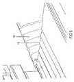
- FIG 5
- eine Teildarstellung des Stapelfachendes mit teilweise heruntergeschwenkter Stapelstütze und Blick auf die profilierte Seite.
- Entsprechend FIG 1 werden die Sendungen 1 in aufrechter Position hintereinander in einem Deckbandsystem zwischen Transportriemen 2 eingeklemmt entlang nebeneinander liegender Stapelfächer 5 einer Sortiermaschine transportiert. Jedes Stapelfach 5 besteht aus einem Stapelboden 7 und einer dazu senkrechten Stapelwand 6. Vor jedem Stapelfach 5 befindet sich eine Weichenanordnung mit einem Weichenflügel 3, um Sendungen entsprechend ihrer Zieladressen gezielt auszuschleusen. Mittels einer an sich bekannten Einstapeleinrichtung 4, auf die hier nicht näher eingegangen wird, werden die Sendungen 1 in das jeweilige Stapelfach 5 an eine Stapelstütze 8 oder an die letzte Sendung eines schon vorhandenen Stapels 11 geleitet. Dort werden sie an der Stapelwand 6 abgebremst und ausgerichtet. Die Stapelstütze 8 ist entlang der Stapelwand 6 gegen eine zur Einstapelstelle gerichtete Federkraft verschiebbar und in Stapelbodenebene schwenkbar geführt.
Der Stapelboden 7 ist, wie in FIG 1 zu erkennen, in Sägezahnform profiliert ausgeführt, wobei die Sägezahnflanken parallel zur Stapelwand 6 verlaufen und die steilen Flanken der Stapelwand 6 zugewandt sind. Die Stapelstütze 8 weist an ihrer auf dem Stapelboden 7 gleitenden Unterseite die gleiche Profilierung auf (FIG 4), so dass beide Profile miteinander kämmen. Dadurch können keine dünnen und biegsamen Sendungen 1 zwischen Stapelboden 7 und Stapelstütze 8 rutschen und ein Zurückprallen oder -gleiten von der Stapelwand 6 wird weitgehend vermieden.
Um genügend Platz für das Schwenkgelenk zu haben, hat die Stapelwand 6 in diesem unteren Bereich einen zurückgesetzten Teil. - Beim Einstapeln erzeugt die entlang der Stapelwand 6 gerichtete Bewegungskomponente der Sendungen 1 eine Kraft, die die Stapelstütze 8 gegen die Federkraft von der Einstapelstelle weg verschiebt. Ist der Stapel 11 mit der Stapelstütze 8 am Ende des Stapelfaches 5 angelangt, entweder weil der Stapel 11 entsprechend groß ist oder weil der von der Einstapeleinrichtung 4 und der Stapelstütze 8 gehaltene Stapel 11 durch Bewegen der Einstapeleinrichtung 4 mit Hilfe einer mit dieser verbundenen Schubstange 10 entsprechend verschoben wurde, erfolgt das Herunterschwenken der Stapelstütze 8 entsprechend FIG 2 und 3, um den Stapel 11 auf eine nachfolgende Auflagefläche 12 schieben zu können. Damit die Sendungen 1 des Stapels 11 nicht in den Spalt zwischen Stapelboden 7 und Auflagefläche 12 fallen, besitzt die Stapelstütze 8 an ihrem oberen Rand einen in der unteren Endstellung annähernd parallel zum Stapelboden 7 ausgerichteten Teil 9, der bei vollständig heruntergeschwenkter Stapelstütze 8 die Lücke überbrückt, die Auflagefläche 12 überlappend. Da auch zwischen Stapelboden 7 und Stapelstütze 8 dünne Sendungen 1 rutschen könnten, sind sowohl der in Stapelrichtung befindliche Abschlussrand 15 des Stapelbodens 8 als auch die dem Abschlussrand 15 beim Schwenken zugewandte Fläche 16 der Stapelstütze 8 so profiliert, dass sie miteinander kämmen. Das Profil ist ebenfalls sägezahnförmig ausgeführt, wobei das Profil an der Stapelstützenseite wegen der Schwenkbewegung kreisbogenförmig verläuft.
Die Sendungen 1 müssten also mit ihren Schmalseiten in diesem Sägezahnprofil verlaufen, um zwischen Stapelbodenrand und Stapelstütze 8 zu gelangen, was aufgrund ihrer Eigensteifigkeit nicht erfolgt. Bevor die Stapelstütze 8 am Ende des Stapelfaches 5 nach unten geschwenkt wird, wird ein nicht dargestellter externer Stützmechanismus neben die Stapelstütze 8 gefahren. Beim Nachuntenschwenken der Stapelstütze übernimmt der Stützmechanismus den Stapel 11 und fährt dann beim weiteren Verfahren des Stapels 11 gesteuert weiter. Befinden sich alle Sendungen 1 des Stapels 11 auf der Auflagefläche 12, so werden durch die Ausnehmungen 13 Stützfinger 14 nach oben gefahren, die dann den Stapel 11 stützen, so dass die Einstapeleinrichtung 4 wieder in die Ausgangsstellung gebracht werden kann.
Claims (6)
- Stapelfach für flache Sendungen in stehender Position, mit einem Stapelboden (7) und einer dazu senkrechten Stapelwand (6), an der die Sendungen (1) im Stapelfach (5) anliegen und mit einer in annähernd horizontaler Stapelrichtung entlang der Stapelwand (6) verschiebbaren, den Stapel (11) haltenden Stapelstütze (8), wobei der Stapelboden (7) mindestens teilweise mit einem Bodenprofil versehen ist und die Stapelstütze (8) mit ihrer auf dem Stapelboden (7) gleitenden Fläche mit dem Bodenprofil kämmend ausgeführt ist,
dadurch gekennzeichnet,
dass die Stapelstütze (8) am Ende des Stapelfaches (5) nach unten in die Ebene des Stapelbodens (7) versenkbar ist derart, dass sie eine Brücke bildet über einen Spalt zwischen dem stromabwärtigen Abschlussrand des Stapelbodens (7) und dem stromaufwärtigen Rand einer stromabwärts anschließenden Auflagefläche (12) für den Stapel (11). - Stapelfach nach Anspruch 1, dadurch gekennzeichnet, dass die Stapelstütze (8) am Ende des Stapelfaches (5) nach unten in die Ebene des Stapelbodens (7) in Stapelrichtung schwenkbar ist.
- Stapelfach nach Anspruch 1, dadurch gekennzeichnet, dass die versenkbare Stapelstütze (8) nach dem Stapelboden (7) vertikal verfahrbar ist und an ihrem oberen Rand einen im heruntergefahrenen Zustand annähernd parallel zum Stapelboden (7) ausgerichteten Teil (9) zum Überbrücken des Spaltes zwischen dem Stapelboden (7) und der nachfolgenden Auflagefläche (12) aufweist, dass auch der in Stapelrichtung befindliche Abschlussrand (15) des Stapelbodens (7) profiliert ausgeführt ist und die dem profilierten Abschlussrand (15) des Stapelbodens (7) beim vertikalen Verfahren zugewandte Fläche (16) der Stapelstütze (8) so profiliert ist, dass sie beim Herunterfahren mit dem profilierten Abschlussrand (15) des Stapelbodens (7) kämmt.
- Stapelfach nach Anspruch 3, dadurch gekennzeichnet, dass die Stapelstütze (8) zum vertikalen Verfahren in der Ebene des Stapelbodens (7) senkrecht zur Stapelrichtung schwenkbar ist.
- Stapelfach nach Anspruch 1, dadurch gekennzeichnet, dass der Stapelboden (7) ein Sägezahnprofil besitzt, wobei die steilen Flanken zur Stapelwand (6) gerichtet sind.
- Stapelfach nach Anspruch 3, dadurch gekennzeichnet, dass die Oberfläche des annähernd parallel zum Stapelboden (7) ausgerichteten Teils (9) der Stapelstütze (8), auf der die Sendungen (1) des Stapels (11) gleiten, das gleiche Oberflächenprofil wie der Stapelboden (7) aufweist.
Applications Claiming Priority (3)
| Application Number | Priority Date | Filing Date | Title |
|---|---|---|---|
| DE10225473A DE10225473C1 (de) | 2002-06-10 | 2002-06-10 | Stapelfach für flache Sendungen |
| DE10225473 | 2002-06-10 | ||
| PCT/DE2003/001528 WO2003104123A1 (de) | 2002-06-10 | 2003-05-12 | Stapelfach für flache sendungen |
Publications (2)
| Publication Number | Publication Date |
|---|---|
| EP1511682A1 EP1511682A1 (de) | 2005-03-09 |
| EP1511682B1 true EP1511682B1 (de) | 2006-04-19 |
Family
ID=27588637
Family Applications (1)
| Application Number | Title | Priority Date | Filing Date |
|---|---|---|---|
| EP03735296A Expired - Lifetime EP1511682B1 (de) | 2002-06-10 | 2003-05-12 | Stapelfach für flache sendungen |
Country Status (5)
| Country | Link |
|---|---|
| US (1) | US7207560B2 (de) |
| EP (1) | EP1511682B1 (de) |
| JP (1) | JP2005529041A (de) |
| DE (2) | DE10225473C1 (de) |
| WO (1) | WO2003104123A1 (de) |
Families Citing this family (8)
| Publication number | Priority date | Publication date | Assignee | Title |
|---|---|---|---|---|
| DE102006029889B3 (de) * | 2006-06-28 | 2008-01-10 | Siemens Ag | Vorrichtung zum Austausch von gestapelten Sendungen zwischen einem Behälter und einer Ablagefläche |
| DE102007055671A1 (de) * | 2007-11-21 | 2009-05-28 | Siemens Ag | Vorrichtung und Verfahren zum Transport eines Gegenstands mittels einer Auflagekomponente |
| US9795995B2 (en) * | 2015-05-06 | 2017-10-24 | Intelligrated Headquarters, Llc | High-speed, dual-sided shoe sorter with offset induct |
| US10144038B2 (en) | 2016-06-10 | 2018-12-04 | United States Postal Service | Systems, devices and methods for sorting items |
| US10112216B2 (en) | 2016-06-10 | 2018-10-30 | United States Postal Services | Systems, devices and methods for sorting items |
| CN108189090B (zh) * | 2018-02-28 | 2023-08-22 | 桂林电子科技大学 | 一种橡胶膜片自动检测与叠膜装置及方法 |
| CN110238067B (zh) * | 2019-06-12 | 2021-11-12 | 上海顶欣机电设备有限公司 | 周转箱分拣装置 |
| CN113546877B (zh) * | 2021-09-22 | 2021-11-26 | 常州市双进电子有限公司 | 一种线路板总成检测系统 |
Family Cites Families (7)
| Publication number | Priority date | Publication date | Assignee | Title |
|---|---|---|---|---|
| GB1303135A (de) * | 1970-02-25 | 1973-01-17 | ||
| JPH02106523A (ja) * | 1988-10-14 | 1990-04-18 | Ricoh Co Ltd | 給紙トレイ |
| JPH0986771A (ja) | 1995-09-21 | 1997-03-31 | Toshiba Corp | 紙葉類処理装置、紙葉類移載装置、紙葉類搬送装置、および紙葉類移載方法 |
| US5871209A (en) * | 1996-03-01 | 1999-02-16 | Currency Systems International, Inc. | Cassette based document handling system |
| US6026967A (en) * | 1997-01-30 | 2000-02-22 | Electrocom Automation | Method and apparatus for sorting flat articles |
| US5993132A (en) * | 1996-03-29 | 1999-11-30 | Siemens Electrocom L.P. | Transferring a stack from a cartridge |
| DE69730451T2 (de) * | 1996-03-29 | 2005-09-01 | Electrocom Automation L.P., Arlington | Kassette zur aufnahme von flachen artikeln |
-
2002
- 2002-06-10 DE DE10225473A patent/DE10225473C1/de not_active Expired - Fee Related
-
2003
- 2003-05-12 WO PCT/DE2003/001528 patent/WO2003104123A1/de not_active Ceased
- 2003-05-12 US US10/516,543 patent/US7207560B2/en not_active Expired - Lifetime
- 2003-05-12 EP EP03735296A patent/EP1511682B1/de not_active Expired - Lifetime
- 2003-05-12 JP JP2004511204A patent/JP2005529041A/ja active Pending
- 2003-05-12 DE DE50303041T patent/DE50303041D1/de not_active Expired - Lifetime
Also Published As
| Publication number | Publication date |
|---|---|
| EP1511682A1 (de) | 2005-03-09 |
| DE50303041D1 (de) | 2006-05-24 |
| JP2005529041A (ja) | 2005-09-29 |
| US20050218042A1 (en) | 2005-10-06 |
| US7207560B2 (en) | 2007-04-24 |
| WO2003104123A1 (de) | 2003-12-18 |
| DE10225473C1 (de) | 2003-08-14 |
Similar Documents
| Publication | Publication Date | Title |
|---|---|---|
| DE2315813C3 (de) | Vorrichtung zum Stapeln von bogenförmigem Material | |
| DE69407236T2 (de) | System zum Stapeln von Blättern mit grossem Aufnahmevermögen und mit einer in der Höhe variierbaren Eingabe und Stapelausrichtung | |
| DE2246811A1 (de) | Sortiergeraet zur verwendung an bearbeitungsvorrichtungen fuer dokumentvorlagen | |
| DE2162918A1 (de) | Verfahren und Vorrichtung zur Eingabe von Blattmaterial in einen Behälter | |
| DE4411597B4 (de) | Blattanleger | |
| DE7715581U1 (de) | Sortiergeraet | |
| EP0440941A2 (de) | Magazin für flache Gegenstände, wie flachliegende Faltschachteln | |
| EP2355938B1 (de) | Postsortieranlage mit mehreren ausgabeeinrichtungen und postsortierverfahren | |
| DE10225473C1 (de) | Stapelfach für flache Sendungen | |
| DE102014202632A1 (de) | Umschlagstation, Rücknahmeautomat und Verfahren zum Umschlagen | |
| EP1590285B1 (de) | Schmales stapelfach für flache sendungen | |
| DE3917373A1 (de) | Vorrichtung zum ablegen von blaettern | |
| DE102009031117B3 (de) | Vorrichtung und Verfahren zur stapelförmigen Ablage von bogenförmigen Substraten | |
| EP0407795A2 (de) | Vorrichtung zur Verbesserung der Stapelqualität von flachen Gegenständen | |
| DE2617334A1 (de) | Einlegevorrichtung fuer eine vorgefaltete endlospapierbahn in einem papierstapler | |
| DE102007034392B4 (de) | Vorrichtung zum Fördern eines Stapels flacher Gegenstände | |
| EP1332891A1 (de) | Postbearbeitungssystem | |
| EP2815994B1 (de) | Anleger für flache Güter, insbesondere Beilagenanleger, und Verfahren zum Abziehen flacher Güter aus einem Stapel | |
| DE3941477A1 (de) | Vorrichtung zum ablegen von kopieblaettern | |
| DE1284131B (de) | Kartenstapeleinrichtung mit hochkant stehenden Karten | |
| DE102011017217A1 (de) | Vorrichtung und Verfahren zum Ablegen von bogenförmigen Produkten | |
| DE102006044137B3 (de) | System und Verfahren zur Sortierung von flachen Poststücken mit Lückensteuerung zur Durchsatzerhöhung | |
| DE102015105586B4 (de) | Verfahren und Sammelvorrichtung zum Sammeln von blattförmigen Gütern | |
| DE69800815T2 (de) | Bogenverteilungsvorrichtung | |
| DE102005003779B3 (de) | Sendungsbehälter einer Sortiermaschine zur gesteuerten Abgabe flacher Sendungen |
Legal Events
| Date | Code | Title | Description |
|---|---|---|---|
| PUAI | Public reference made under article 153(3) epc to a published international application that has entered the european phase |
Free format text: ORIGINAL CODE: 0009012 |
|
| 17P | Request for examination filed |
Effective date: 20041103 |
|
| AK | Designated contracting states |
Kind code of ref document: A1 Designated state(s): AT BE BG CH CY CZ DE DK EE ES FI FR GB GR HU IE IT LI LU MC NL PT RO SE SI SK TR |
|
| RBV | Designated contracting states (corrected) |
Designated state(s): BE DE FR GB IT |
|
| GRAP | Despatch of communication of intention to grant a patent |
Free format text: ORIGINAL CODE: EPIDOSNIGR1 |
|
| GRAS | Grant fee paid |
Free format text: ORIGINAL CODE: EPIDOSNIGR3 |
|
| GRAA | (expected) grant |
Free format text: ORIGINAL CODE: 0009210 |
|
| AK | Designated contracting states |
Kind code of ref document: B1 Designated state(s): BE DE FR GB IT |
|
| REG | Reference to a national code |
Ref country code: GB Ref legal event code: FG4D Free format text: NOT ENGLISH |
|
| REF | Corresponds to: |
Ref document number: 50303041 Country of ref document: DE Date of ref document: 20060524 Kind code of ref document: P |
|
| GBT | Gb: translation of ep patent filed (gb section 77(6)(a)/1977) |
Effective date: 20060531 |
|
| ET | Fr: translation filed | ||
| PLBE | No opposition filed within time limit |
Free format text: ORIGINAL CODE: 0009261 |
|
| STAA | Information on the status of an ep patent application or granted ep patent |
Free format text: STATUS: NO OPPOSITION FILED WITHIN TIME LIMIT |
|
| 26N | No opposition filed |
Effective date: 20070122 |
|
| PGFP | Annual fee paid to national office [announced via postgrant information from national office to epo] |
Ref country code: BE Payment date: 20070511 Year of fee payment: 5 |
|
| BERE | Be: lapsed |
Owner name: SIEMENS A.G. Effective date: 20080531 |
|
| PG25 | Lapsed in a contracting state [announced via postgrant information from national office to epo] |
Ref country code: BE Free format text: LAPSE BECAUSE OF NON-PAYMENT OF DUE FEES Effective date: 20080531 |
|
| REG | Reference to a national code |
Ref country code: FR Ref legal event code: PLFP Year of fee payment: 14 |
|
| PGFP | Annual fee paid to national office [announced via postgrant information from national office to epo] |
Ref country code: GB Payment date: 20160512 Year of fee payment: 14 |
|
| REG | Reference to a national code |
Ref country code: FR Ref legal event code: PLFP Year of fee payment: 15 |
|
| GBPC | Gb: european patent ceased through non-payment of renewal fee |
Effective date: 20170512 |
|
| PG25 | Lapsed in a contracting state [announced via postgrant information from national office to epo] |
Ref country code: GB Free format text: LAPSE BECAUSE OF NON-PAYMENT OF DUE FEES Effective date: 20170512 |
|
| REG | Reference to a national code |
Ref country code: FR Ref legal event code: PLFP Year of fee payment: 16 |
|
| PG25 | Lapsed in a contracting state [announced via postgrant information from national office to epo] |
Ref country code: IT Free format text: LAPSE BECAUSE OF NON-PAYMENT OF DUE FEES Effective date: 20190512 |
|
| PGFP | Annual fee paid to national office [announced via postgrant information from national office to epo] |
Ref country code: FR Payment date: 20200518 Year of fee payment: 18 |
|
| PGFP | Annual fee paid to national office [announced via postgrant information from national office to epo] |
Ref country code: DE Payment date: 20200720 Year of fee payment: 18 |
|
| REG | Reference to a national code |
Ref country code: DE Ref legal event code: R119 Ref document number: 50303041 Country of ref document: DE |
|
| PG25 | Lapsed in a contracting state [announced via postgrant information from national office to epo] |
Ref country code: DE Free format text: LAPSE BECAUSE OF NON-PAYMENT OF DUE FEES Effective date: 20211201 |
|
| PG25 | Lapsed in a contracting state [announced via postgrant information from national office to epo] |
Ref country code: FR Free format text: LAPSE BECAUSE OF NON-PAYMENT OF DUE FEES Effective date: 20210531 |