EP1510838A1 - Polarisationsstrahlenteiler, optisches System und Bildanzeigevorrichtung damit - Google Patents
Polarisationsstrahlenteiler, optisches System und Bildanzeigevorrichtung damit Download PDFInfo
- Publication number
- EP1510838A1 EP1510838A1 EP04020668A EP04020668A EP1510838A1 EP 1510838 A1 EP1510838 A1 EP 1510838A1 EP 04020668 A EP04020668 A EP 04020668A EP 04020668 A EP04020668 A EP 04020668A EP 1510838 A1 EP1510838 A1 EP 1510838A1
- Authority
- EP
- European Patent Office
- Prior art keywords
- beam splitter
- light
- polarization beam
- polarized
- refractive index
- Prior art date
- Legal status (The legal status is an assumption and is not a legal conclusion. Google has not performed a legal analysis and makes no representation as to the accuracy of the status listed.)
- Granted
Links
- 230000010287 polarization Effects 0.000 title claims abstract description 75
- 230000003287 optical effect Effects 0.000 title claims description 30
- 230000014509 gene expression Effects 0.000 claims description 36
- 238000002834 transmittance Methods 0.000 claims description 2
- 239000010410 layer Substances 0.000 description 46
- 239000003989 dielectric material Substances 0.000 description 18
- 239000010408 film Substances 0.000 description 16
- 238000010276 construction Methods 0.000 description 14
- GWEVSGVZZGPLCZ-UHFFFAOYSA-N Titan oxide Chemical compound O=[Ti]=O GWEVSGVZZGPLCZ-UHFFFAOYSA-N 0.000 description 8
- 239000000463 material Substances 0.000 description 8
- OGIDPMRJRNCKJF-UHFFFAOYSA-N titanium oxide Inorganic materials [Ti]=O OGIDPMRJRNCKJF-UHFFFAOYSA-N 0.000 description 7
- 230000005540 biological transmission Effects 0.000 description 6
- 238000005102 attenuated total reflection Methods 0.000 description 3
- 230000000694 effects Effects 0.000 description 3
- 239000004973 liquid crystal related substance Substances 0.000 description 3
- 239000010409 thin film Substances 0.000 description 3
- VYPSYNLAJGMNEJ-UHFFFAOYSA-N Silicium dioxide Chemical compound O=[Si]=O VYPSYNLAJGMNEJ-UHFFFAOYSA-N 0.000 description 2
- 230000002159 abnormal effect Effects 0.000 description 2
- 238000004364 calculation method Methods 0.000 description 2
- 229910003460 diamond Inorganic materials 0.000 description 2
- 239000010432 diamond Substances 0.000 description 2
- 230000005684 electric field Effects 0.000 description 2
- 238000004519 manufacturing process Methods 0.000 description 2
- 238000000926 separation method Methods 0.000 description 2
- 238000004088 simulation Methods 0.000 description 2
- 239000000853 adhesive Substances 0.000 description 1
- 238000004458 analytical method Methods 0.000 description 1
- 230000008033 biological extinction Effects 0.000 description 1
- 229910052681 coesite Inorganic materials 0.000 description 1
- 229910052906 cristobalite Inorganic materials 0.000 description 1
- 238000005530 etching Methods 0.000 description 1
- 239000011521 glass Substances 0.000 description 1
- 238000010030 laminating Methods 0.000 description 1
- QSHDDOUJBYECFT-UHFFFAOYSA-N mercury Chemical compound [Hg] QSHDDOUJBYECFT-UHFFFAOYSA-N 0.000 description 1
- 229910052753 mercury Inorganic materials 0.000 description 1
- 230000000737 periodic effect Effects 0.000 description 1
- 239000005342 prism glass Substances 0.000 description 1
- 239000004065 semiconductor Substances 0.000 description 1
- 239000000377 silicon dioxide Substances 0.000 description 1
- 239000002356 single layer Substances 0.000 description 1
- 229910052682 stishovite Inorganic materials 0.000 description 1
- 229910052905 tridymite Inorganic materials 0.000 description 1
Images




Classifications
-
- G—PHYSICS
- G02—OPTICS
- G02B—OPTICAL ELEMENTS, SYSTEMS OR APPARATUS
- G02B5/00—Optical elements other than lenses
- G02B5/30—Polarising elements
- G02B5/3025—Polarisers, i.e. arrangements capable of producing a definite output polarisation state from an unpolarised input state
-
- G—PHYSICS
- G02—OPTICS
- G02B—OPTICAL ELEMENTS, SYSTEMS OR APPARATUS
- G02B27/00—Optical systems or apparatus not provided for by any of the groups G02B1/00 - G02B26/00, G02B30/00
- G02B27/28—Optical systems or apparatus not provided for by any of the groups G02B1/00 - G02B26/00, G02B30/00 for polarising
- G02B27/283—Optical systems or apparatus not provided for by any of the groups G02B1/00 - G02B26/00, G02B30/00 for polarising used for beam splitting or combining
Definitions
- This invention relates to a polarization beam splitter used in lights of a plurality of wavelengths or bands, and relates, for example, to various optical apparatuses such as an image taking optical system, a projection optical system (projector), an image processing apparatus and a semiconductor manufacturing apparatus.
- various optical apparatuses such as an image taking optical system, a projection optical system (projector), an image processing apparatus and a semiconductor manufacturing apparatus.
- a polarization beam splitter using dielectric material multi-layer film comprising two kinds of media. As shown in Fig. 12 of the accompanying drawings, it uses transmission (19) at Brewster's angle regarding P polarized light (18) incident on multi-layer film 17, and effects reflection (21) by the interference of the multi-layer film regarding S polarized light (20).
- n P n 2 H n 2 L sin 2 ⁇ B (n 2 H + n 2 L )
- reflecting film by multi-layer film interference is constituted by the use of the reflectances of the medium H of the high refractive index layer and the medium L of the low refractive index layer. It is possible to realize reflecting film for the entire area of visible light by 20 to 40 layers.
- the S polarized light by increasing the number of the layers of the film, it is possible to secure an angle characteristic and a wavelength characteristic widely.
- the wavelength used is a wavelength supposed to be used in an optical element.
- the wavelength band is defined as a used wavelength area
- the central wavelength thereof is defined as the used wavelength.
- the used wavelength is defined as the central wavelength of a visible area even if light incident on the element includes lights of the other wavelength areas than the visible area infrared to ultraviolet.
- High refractive index layers (H layers) 15 of TiO 2 or the like and low refractive index layers (L layers) 16 of SiO 2 or the like were alternately laminated, and they were etched so that the ratio of the pitch (period) of periodic structure to the medium (grating width), i.e., a filling factor f, might be about 0.5.
- the period of the rectangular grating forms structural birefringence as structure shorter than the wavelength.
- the refractive index difference between the H layer and the L layer is great, and in the direction TM, the refractive index difference between the H layer and the L layer is small.
- the condition of the Brewster's angle is satisfied in the direction TM and the P polarized light can be transmitted.
- the thickness of each layer is independent on the condition of the Brewster's angle and therefore, by optimizing the film thicknesses of the H layer and the L layer, it is possible to form dielectric material multi-layer film. Thereby, the S polarized light is reflected and the function as a polarization beam splitter is obtained.
- the condition of Brewster's angle is used for the transmission of P polarized light and therefore, the refractive indices of a prism glass material and the medium of the thin film are subject to the limitation of expression (2) above and also, it is difficult to secure an angle characteristic widely. This is not improved even if the number of layers is increased.
- the refractive index difference of the high molecular material between a normal ray and an abnormal ray is not great and therefore, to effect total reflection, the incidence angle must be about 60° or greater, and this leads to the problem that the use of a usable optical system is limited.
- this element uses a high molecular material or the like as a birefringent element and is therefore inferior from the viewpoints of heat resistance and light resistance.
- the construction is complicated and the manufacturing cost is high, and the condition of the Brewster's angle is used for the transmission of P polarized light and therefore, like the dielectric material multi-layer film, it is difficult to obtain a wide angle characteristic.
- the incidence angle becomes great, the refractive index difference between TE and TM becomes null and therefore, the increase in the reflectance at an incidence angle exceeding the Brewster's angle is greater than when dielectric material thin film is used, and this hinders widening the angle characteristic and therefore, an element having sufficient performance cannot be obtained.
- the polarization beam splitter of the present invention is a polarization beam splitter having a polarized beam splitting layer having structure in which a plurality of gratings parallel to a first direction are periodically disposed in a second direction orthogonal to the first direction, and is characterized in that of light incident on the polarization beam splitter, chiefly light of a polarized component parallel to the first direction is transmitted therethrough and chiefly light of a polarized component parallel to the second direction is reflected.
- the transmittance of the light of the polarized component parallel to the first direction be 90% or higher, and the reflectance of the light of the polarized component parallel to the second direction be 90% or higher.
- the used wavelength area be a visible light area.
- light of an ultraviolet wavelength area or light of an infrared wavelength area may be used.
- the plurality of gratings be arranged at a period shorter than the used wavelength.
- the light of the polarized component parallel to the second direction be reflected by the use of total reflection.
- a surface of the polarization beam splitter on which a ray is incident is defined as a first surface, and this first surface and the polarized beam splitting layer are arranged so as to face each other at an angle which is not parallel, and a surface containing a normal to the first surface and a normal to the polarized beam splitting layer is defined as a second surface, the first direction be substantially parallel to the second surface.
- the polarization beam splitter have a shape of a square pole type having a diamond-shaped bottom surface obtained by two transparent members of substantially the same triangle pole shape having an isosceles triangle as a bottom surface having had their sides including the bottom sides of their respective isosceles triangles joined to each other. It is better if the first direction is disposed so as to be parallel to the diamond-shaped bottom surface.
- the material of the plurality of gratings be a dielectric material, and the space between the plurality of gratings be filled with air.
- the dielectric material is titanium oxide (TiO 2 ). It is desirable that when of the period at which the plurality of gratings are arranged, the rate the dielectric material occupies if f, 0.2 ⁇ f ⁇ 0.8 ⁇ (6) be satisfied.
- the polarized beam splitting layer be sandwiched between two optical members.
- the absolute value of the photoelasticity constant of the two optical members be smaller than 0.1 ⁇ 10 -8 cm 2 /N. It is desirable that the two optical members have the same refractive index.
- the refractive index of the medium of the optical members and the effective refractive index of the polarized beam splitting layer for the light having the polarized component parallel to the first direction are made substantially equal to each other.
- the thickness d of the polarized beam splitting layer is such that the relation thereof with the used wavelength ⁇ S on the shortest wavelength side of the light of the used wavelength area satisfies the following conditional expression: 0.5 ⁇ d/ ⁇ s
- the polarization beam splitter of the present invention has a polarized beam splitting layer having structure in which a plurality of gratings parallel to a first direction are periodically disposed in a second direction orthogonal to the first direction, and is characterized in that of light incident on the polarization beam splitter, chiefly light of a polarized component parallel to the first direction is transmitted, and chiefly light of a polarized component parallel to the second direction is reflected.
- P polarized light and S polarized light are ordinary names, and polarized light in which an electric field vibrates in parallelism to an incidence flat surface (generally a surface containing an incident ray and a normal to a boundary surface (now the surface of a polarizing element); in the present case, it is defined as a surface containing an incident ray, a reflected ray and a transmitted ray) is P polarized light, and polarized light in which an electric field vibrates in a direction orthogonal to the incidence flat surface is S polarized light.
- the image displaying apparatus of this application is characterized by at least one display element, an illuminating optical system for illuminating the aforementioned at least one display element with light from a light source, and a polarized beam splitting as described above.
- the image display apparatus have a projection optical system for projecting light from the aforementioned at least one display element onto a projection surface.
- the aforementioned ' at least one display element be a reflection type display element. Also, it is better if the aforementioned at least one display element be a plurality of display elements, and be designed to have a color resolving system for color-resolving light from a light source for each wavelength (each color) when it is directed to the plurality of display elements, and a color combining system for combining reflected lights from the plurality of display elements.
- a color resolving system for color-resolving light from a light source for each wavelength (each color) when it is directed to the plurality of display elements and a color combining system for combining reflected lights from the plurality of display elements.
- at least one of the color resolving system and the color combining system have the above polarization beam splitter.
- each of the color resolving system and the color combining system has at least one of above described polarization beam splitter.
- Fig. 1 shows the construction of a polarization beam splitter according to a first embodiment of the present invention.
- Tables 1 and 2 below show the numerical values of the constructions by Design Examples 1 and 2 of a grating of SWS used in this first embodiment.
- a polarized beam splitting layer is inclined at 45° with respect to the incidence surface of a prism.
- the grating of SWS as shown in Fig. 2, is disposed in parallelism to the incidence plane, and is designed to reflect S polarized light and transmit P polarized light therethrough.
- This grating of SWS adopts such a construction as shown in Figs. 3A and 3B, and as shown in Fig. 3B, the cross-sectional structure of the grating (a direction parallel to this grating, i.e., a direction perpendicular to the plane of the drawings sheet of Fig.
- a direction is of rectangular grating structure (the pitch direction of this grating, i.e., a direction parallel to the plane of the drawing sheet of Fig. 3B is referred to as B direction) in which air 24 and TiO 2 25 (other medium will also do) are one-dimensionally alternately repeated, and is of very simple structure in which polarized light separation is realized by this single layer alone.
- the portion of the grating of TiO 2 may be formed by laminating a plurality of different media with respect to the height direction of the grating (i.e., the vertical direction in the plane of the drawing sheet of Fig. 3B), and the layer of air may be replaced by other medium than air.
- the height of the grating is 700 ⁇ m, and sufficiently satisfies conditional expression (6) for the light of the wavelength in the visible light area (light of the used wavelength area).
- Conditional expression (6) is representative of a condition for completely achieving total reflection.
- the incidence angle thereof is a critical angle ⁇ C or greater
- the light is not at all transmitted, but is totally reflected.
- ⁇ C critical angle
- ⁇ C critical angle
- evanescent wave oozes in a very minute area near a boundary surface. If there is the following medium in the reach area of this light, the light will be transmitted. This phenomenon is attenuated total reflection (ATR), and a conditional expression for preventing this ATR is (6).
- a material having a refractive index as high as about 1.847 is selected as the glass material of the prism, and TiO 2 having a refractive index as high as about 2.339 is also used as a dielectric material constituting the grating, and the filling factor of the grating is set to the range of conditional expressions (7) and (8).
- Conditional expression (7) prescribes the condition for the transmission of a polarized component of A direction to the grating structure
- conditional expression (8) prescribes the condition for the total reflection of a polarized component of B direction.
- TE is the polarized component of A direction
- TM is the polarized component of B direction
- the refractive indices in the respective directions of the structural birefringence are given by the aforementioned expressions (4) and (5).
- the Brewster's angle is given by expression (5), and a condition range set to expression (10) substituted for the right side of expression (5) is expression (2).
- expression (2) is the value of tan of the Brewster's angle ⁇ B, and prescribes the upper limit and lower limit of this value. If the upper limit and the lower limit are exceeded, that is, if the difference between the refractive indices of two media becomes great, reflectance increases and the transmission of the polarized component of A direction is hindered.
- expression (3) is the value of sin of the critical angle ⁇ C, and when this value is smaller than the incidence angle, total reflection occurs in the angle area of the entire light beam.
- the effective refractive indices of the gratings become substantially the same refractive indices regarding P polarized light, and cause a great refractive index difference regarding S polarized light, and the rays of the respective polarized lights are transmitted and totally reflected.
- Figs. 9A to 9C show the result of the simulation of the performance by the rigorous coupled-wave analysis (RCWA) of this design value.
- RCWA rigorous coupled-wave analysis
- Conditional expression (6) prescribes the range of f (filling factor), and is a condition for chiefly causing structural birefringence efficiently.
- f filling factor
- Fig. 8A the effective refractive indices in the respective polarizing directions can be found by the above-mentioned expressions (4) and (5), and they are graphed in Fig. 8B.
- to select f within the range of conditional expression (6) is to efficiently utilize the effective refractive index.
- Figs. 4A and 4B show the grating structure of SWS of a polarization beam splitter according to a second embodiment of the present invention.
- Tables 1 and 2 below, there is shown the construction by Design Example 2 of the grating of SWS according to the second embodiment.
- a polarized beam splitting layer is inclined at 45° with respect to the incidence surface of the prism, and is designed to reflect S polarized light and transmit P polarized light therethrough.
- the cross-sectional structure of the grating is rectangular grating structure in which air and TiO 2 are alternately repeated.
- it is structure satisfying conditional expressions (7) and (8).
- f is set so as to become a value approximate to the lower limit of the condition of expression (7), whereby regarding the total reflection of expression (8), the angle characteristic can be set widely on the short wavelength side.
- Figs. 10A-10C show the result of the simulation of the performance by RCWA of this design value.
- the total reflection condition widens on the low incidence angle side. In exchange for it, the reflectance of P polarized light is high on the high incidence angle side.
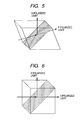
- Fig. 5 shows the construction of a polarization beam splitter prism according to a third embodiment of the present invention.
- the polarization beam splitter of Design Example shown in Table 1 and Table 2 is inserted in the prism inclined into a diamond shape.
- Incident light from the left side of Fig. 5 is incident on a prism surface perpendicularly thereto, and is incident on the polarization beam splitter at an angle greater than 45°.
- a greater incidence angle is more advantageous, but the prism is inclined into a diamond shape at about 10° as described above, whereby the incidence angle can be changed by 5°.
- Fig. 6 shows the construction of a polarization beam splitter prism according to a fourth embodiment of the present invention.
- the polarization beam splitter of Design Example 1 is inserted in a prism of 45°.
- the direction of the grating is orthogonal to the incidence plane.
- This embodiment is one in which the transmission and reflection of polarized lights to be separated which cannot be realized by a polarization beam splitter of multi-layer film using the ordinary Brewster's angle are made converse. It is possible to control the direction in which light is to be directed and the direction of polarization.
- Fig. 7 shows a reflection type image modulating apparatus using the polarization beam splitter of the present invention which is a fifth embodiment of the present invention.
- the reference numeral 1 designates a light source comprising a high pressure mercury lamp or the like
- the reference numeral 2 denotes a reflector for radiating light from the light source 1 in a predetermined direction
- the reference numeral 3 designates an integrator for forming an illuminating area having uniform illuminating intensity, and comprised of fly-eye lenses 3a and 3b
- the reference numeral 4 denotes a polarized light converting element for converting non-polarized light into a predetermined linearly polarized light (making it uniform in a polarizing direction)
- the reference numeral 5 designates a condenser lens for condensing the illuminating light
- the reference numeral 6 denotes a mirror
- the reference numeral 7 designates a field lens for making the illuminating light into telecentric light
- the reference numeral 8
- the reference characters 10a and 10b denote color selective phase difference plates for changing (rotating) the polarizing directions of lights of predetermined wavelength areas by 90°
- the reference characters 11r, 11g and 11b designate reflection type liquid crystal display elements for reflecting the incident illuminating light and also, modulating it in conformity with an image signal and forming image light
- the reference characters 12r, 12g and 12b denote quarter phase difference plates
- the reference numeral 14 designates a projection lens system (which may include a mirror or may be comprised of mirror alone).
- the polarization beam splitter of the present invention is a polarization beam splitter having a polarized beam splitting layer having structure in which a plurality of gratings parallel to a first direction are periodically disposed in a second direction orthogonal to the first direction, and of light incident on the polarization beam splitter, chiefly light of a polarized component parallel to the first direction is transmitted therethrough, and chiefly light of a polarized component parallel to the second direction is reflected.
Landscapes
- Physics & Mathematics (AREA)
- General Physics & Mathematics (AREA)
- Optics & Photonics (AREA)
- Polarising Elements (AREA)
- Projection Apparatus (AREA)
Applications Claiming Priority (2)
| Application Number | Priority Date | Filing Date | Title |
|---|---|---|---|
| JP2003308787A JP4593894B2 (ja) | 2003-09-01 | 2003-09-01 | 光学式エンコーダ |
| JP2003308787 | 2003-09-01 |
Publications (2)
| Publication Number | Publication Date |
|---|---|
| EP1510838A1 true EP1510838A1 (de) | 2005-03-02 |
| EP1510838B1 EP1510838B1 (de) | 2016-03-23 |
Family
ID=34101284
Family Applications (1)
| Application Number | Title | Priority Date | Filing Date |
|---|---|---|---|
| EP04020668.2A Expired - Lifetime EP1510838B1 (de) | 2003-09-01 | 2004-08-31 | Polarisationsstrahlenteiler, optisches System und Bildanzeigevorrichtung damit |
Country Status (3)
| Country | Link |
|---|---|
| US (2) | US7116478B2 (de) |
| EP (1) | EP1510838B1 (de) |
| JP (1) | JP4593894B2 (de) |
Cited By (4)
| Publication number | Priority date | Publication date | Assignee | Title |
|---|---|---|---|---|
| CN109085701A (zh) * | 2018-07-26 | 2018-12-25 | 京东方科技集团股份有限公司 | 分光系统及制造方法以及包含其的光谱检测仪及制造方法 |
| EP3460540A1 (de) * | 2017-09-25 | 2019-03-27 | Canon Kabushiki Kaisha | Polarisationsstrahlenteiler und bildprojektionsvorrichtung |
| US11344884B2 (en) | 2018-07-26 | 2022-05-31 | Boe Technology Group Co., Ltd. | Microfluidic apparatus, method of detecting substance in microfluidic apparatus, and spectrometer |
| CN119575649A (zh) * | 2025-01-16 | 2025-03-07 | 广东工业大学 | 一种基于微纳光栅的偏振分束器参数调优方法及系统 |
Families Citing this family (31)
| Publication number | Priority date | Publication date | Assignee | Title |
|---|---|---|---|---|
| EP1672395B1 (de) * | 2003-10-07 | 2010-12-15 | Nalux Co. Ltd. | Polarisierendes element und optisches system mit polarisierendem element |
| JP2006133403A (ja) * | 2004-11-04 | 2006-05-25 | Canon Inc | 偏光分離素子 |
| US7570424B2 (en) | 2004-12-06 | 2009-08-04 | Moxtek, Inc. | Multilayer wire-grid polarizer |
| US20080055719A1 (en) * | 2006-08-31 | 2008-03-06 | Perkins Raymond T | Inorganic, Dielectric Grid Polarizer |
| US7961393B2 (en) | 2004-12-06 | 2011-06-14 | Moxtek, Inc. | Selectively absorptive wire-grid polarizer |
| US7199857B2 (en) * | 2005-04-05 | 2007-04-03 | Regal Cinemedia Corporation | Digital control unit for projector automation systems |
| JP2007041207A (ja) * | 2005-08-02 | 2007-02-15 | Mitsubishi Electric Corp | 偏光分離素子 |
| US20070146880A1 (en) * | 2005-12-27 | 2007-06-28 | Jvc Americas Corporation | Optical device for splitting an incident light into simultaneously spectrally separated and orthogonally polarized light beams having complementary primary color bands |
| CN100514183C (zh) * | 2006-05-29 | 2009-07-15 | 晶荧光学科技有限公司 | 便携式电子设备 |
| US8755113B2 (en) | 2006-08-31 | 2014-06-17 | Moxtek, Inc. | Durable, inorganic, absorptive, ultra-violet, grid polarizer |
| JP5051830B2 (ja) * | 2007-05-22 | 2012-10-17 | 株式会社リコー | 偏光照明装置および投射型画像表示装置 |
| US7618178B2 (en) * | 2007-06-11 | 2009-11-17 | SKC Haas Display Films Co., Lt.d | Backlight containing formed birefringence reflective polarizer |
| CN100592138C (zh) * | 2007-07-13 | 2010-02-24 | 鸿富锦精密工业(深圳)有限公司 | 液晶投影仪的光学系统 |
| DE102007047681B4 (de) * | 2007-10-05 | 2014-07-10 | Fraunhofer-Gesellschaft zur Förderung der angewandten Forschung e.V. | Monolithischer dielektrischer Spiegel |
| US8379187B2 (en) | 2007-10-24 | 2013-02-19 | Nikon Corporation | Optical unit, illumination optical apparatus, exposure apparatus, and device manufacturing method |
| JP4979549B2 (ja) * | 2007-11-20 | 2012-07-18 | キヤノン株式会社 | 偏光分離素子及びそれを有する光学機器 |
| US20100158521A1 (en) * | 2008-12-18 | 2010-06-24 | Alcatel-Lucent Usa Inc. | Optical mixer for coherent detection of polarization-multiplexed signals |
| JP5606052B2 (ja) * | 2009-01-13 | 2014-10-15 | キヤノン株式会社 | 光学素子 |
| US8588565B2 (en) | 2009-03-20 | 2013-11-19 | Alcatel Lucent | Coherent optical detector having a multifunctional waveguide grating |
| US8248696B2 (en) | 2009-06-25 | 2012-08-21 | Moxtek, Inc. | Nano fractal diffuser |
| US8494315B2 (en) * | 2009-12-17 | 2013-07-23 | Alcatel Lucent | Photonic integrated circuit having a waveguide-grating coupler |
| US9151958B2 (en) | 2010-09-02 | 2015-10-06 | Raytheon Company | Display system using a pair of polarized sources with a 3-D display mode and two 2-D display modes |
| US8913321B2 (en) | 2010-09-21 | 2014-12-16 | Moxtek, Inc. | Fine pitch grid polarizer |
| US8611007B2 (en) | 2010-09-21 | 2013-12-17 | Moxtek, Inc. | Fine pitch wire grid polarizer |
| US8873144B2 (en) | 2011-05-17 | 2014-10-28 | Moxtek, Inc. | Wire grid polarizer with multiple functionality sections |
| US8913320B2 (en) | 2011-05-17 | 2014-12-16 | Moxtek, Inc. | Wire grid polarizer with bordered sections |
| US8922890B2 (en) | 2012-03-21 | 2014-12-30 | Moxtek, Inc. | Polarizer edge rib modification |
| US20140204459A1 (en) * | 2013-01-22 | 2014-07-24 | Cynosure Photonics Corp. | High efficiency light combination module of projection system |
| US9632223B2 (en) | 2013-10-24 | 2017-04-25 | Moxtek, Inc. | Wire grid polarizer with side region |
| US20160116754A1 (en) * | 2014-10-28 | 2016-04-28 | Moxtek, Inc. | Dielectric Polarizing Beam Splitter |
| CN112433364A (zh) * | 2020-11-16 | 2021-03-02 | 邵阳学院 | 基于电磁超介质反常的传输率和高通滤波的滤波器设计方法 |
Citations (2)
| Publication number | Priority date | Publication date | Assignee | Title |
|---|---|---|---|---|
| US5042925A (en) * | 1989-11-14 | 1991-08-27 | U.S. Philips Corporation | Polarization-sensitive beam splitter having a polarizing birefringent oriented polymer adhesive layer |
| WO2000057215A1 (en) * | 1999-03-22 | 2000-09-28 | Mems Optical, Inc. | Diffractive selectively polarizing beam splitter and beam routing prisms produced thereby |
Family Cites Families (7)
| Publication number | Priority date | Publication date | Assignee | Title |
|---|---|---|---|---|
| JPS5627106A (en) * | 1979-08-10 | 1981-03-16 | Canon Inc | Beam splitter |
| US5912762A (en) * | 1996-08-12 | 1999-06-15 | Li; Li | Thin film polarizing device |
| US6288840B1 (en) * | 1999-06-22 | 2001-09-11 | Moxtek | Imbedded wire grid polarizer for the visible spectrum |
| US6447120B2 (en) * | 1999-07-28 | 2002-09-10 | Moxtex | Image projection system with a polarizing beam splitter |
| JP2003215344A (ja) * | 2001-03-29 | 2003-07-30 | Seiko Epson Corp | 偏光子、およびこの偏光子を用いた光学機器 |
| JP4325135B2 (ja) * | 2001-09-25 | 2009-09-02 | セイコーエプソン株式会社 | 照明装置およびプロジェクタ |
| EP1300698B1 (de) * | 2001-10-01 | 2011-11-02 | Sony Corporation | Polarisationsselektives Prisma für einen Projektor |
-
2003
- 2003-09-01 JP JP2003308787A patent/JP4593894B2/ja not_active Expired - Fee Related
-
2004
- 2004-08-31 EP EP04020668.2A patent/EP1510838B1/de not_active Expired - Lifetime
- 2004-08-31 US US10/930,128 patent/US7116478B2/en not_active Expired - Fee Related
-
2006
- 2006-09-12 US US11/531,138 patent/US7301700B2/en not_active Expired - Fee Related
Patent Citations (2)
| Publication number | Priority date | Publication date | Assignee | Title |
|---|---|---|---|---|
| US5042925A (en) * | 1989-11-14 | 1991-08-27 | U.S. Philips Corporation | Polarization-sensitive beam splitter having a polarizing birefringent oriented polymer adhesive layer |
| WO2000057215A1 (en) * | 1999-03-22 | 2000-09-28 | Mems Optical, Inc. | Diffractive selectively polarizing beam splitter and beam routing prisms produced thereby |
Non-Patent Citations (2)
| Title |
|---|
| DEER YI ET AL: "Broadband polarizing beam splitter based on the form birefringence of a subwavelength grating in the quasi-static domain", OPTICS LETTERS OPT. SOC. AMERICA USA, vol. 29, no. 7, 1 April 2004 (2004-04-01), pages 754 - 756, XP002307471, ISSN: 0146-9592 * |
| HONKANEN M ET AL: "INVERSE METAL-STRIP POLARIZERS", APPLIED PHYSICS B: LASERS AND OPTICS, SPRINGER INTERNATIONAL, BERLIN, DE, vol. B68, no. 1, 1999, pages 81 - 85, XP000791924, ISSN: 0946-2171 * |
Cited By (4)
| Publication number | Priority date | Publication date | Assignee | Title |
|---|---|---|---|---|
| EP3460540A1 (de) * | 2017-09-25 | 2019-03-27 | Canon Kabushiki Kaisha | Polarisationsstrahlenteiler und bildprojektionsvorrichtung |
| CN109085701A (zh) * | 2018-07-26 | 2018-12-25 | 京东方科技集团股份有限公司 | 分光系统及制造方法以及包含其的光谱检测仪及制造方法 |
| US11344884B2 (en) | 2018-07-26 | 2022-05-31 | Boe Technology Group Co., Ltd. | Microfluidic apparatus, method of detecting substance in microfluidic apparatus, and spectrometer |
| CN119575649A (zh) * | 2025-01-16 | 2025-03-07 | 广东工业大学 | 一种基于微纳光栅的偏振分束器参数调优方法及系统 |
Also Published As
| Publication number | Publication date |
|---|---|
| US20070058251A1 (en) | 2007-03-15 |
| JP4593894B2 (ja) | 2010-12-08 |
| US20050078372A1 (en) | 2005-04-14 |
| EP1510838B1 (de) | 2016-03-23 |
| US7116478B2 (en) | 2006-10-03 |
| US7301700B2 (en) | 2007-11-27 |
| JP2005077819A (ja) | 2005-03-24 |
Similar Documents
| Publication | Publication Date | Title |
|---|---|---|
| US7116478B2 (en) | Polarization beam splitter and optical system using the same, and image displaying apparatus, using the same | |
| US7369186B2 (en) | Polarizing beam splitter featuring stacked grating layers and display including the same | |
| US6288840B1 (en) | Imbedded wire grid polarizer for the visible spectrum | |
| US7236655B2 (en) | Polarization element and optical device using polarization element | |
| US7012747B2 (en) | Polarizing beam splitter and polarizer using the same | |
| JP4510547B2 (ja) | 偏光分離素子及びそれを有する投影装置 | |
| EP1390811A4 (de) | Bildprojektionssystem mit einem polarisierenden strahlverzweiger | |
| US7095538B2 (en) | Band-pass filter and image display apparatus | |
| JP4814002B2 (ja) | 位相板の製造方法・光学素子および画像投射装置 | |
| EP2128666B1 (de) | Optisches Element und optische Vorrichtung | |
| JP2006133402A (ja) | 偏光分離素子及びそれを有する光学系 | |
| EP1873573A1 (de) | Platte zur Polarisationsrückgewinnung | |
| JP4537115B2 (ja) | 偏光分離プリズム | |
| US6859315B2 (en) | Polarization beam splitter and method of producing the same | |
| JP5188524B2 (ja) | 偏光分離素子 | |
| JP4541757B2 (ja) | 偏光素子 | |
| JP2005321562A5 (de) | ||
| JP2004045853A (ja) | 光学多層膜及び光学素子 | |
| JP2003029032A (ja) | 偏光分離変換素子 | |
| JP2003066231A (ja) | 偏光ビームスプリッタ | |
| JP2000137117A (ja) | 偏光分離素子および偏光変換光学素子 | |
| JP2002182026A (ja) | 光学素子およびそれを用いた分光装置 |
Legal Events
| Date | Code | Title | Description |
|---|---|---|---|
| PUAI | Public reference made under article 153(3) epc to a published international application that has entered the european phase |
Free format text: ORIGINAL CODE: 0009012 |
|
| AK | Designated contracting states |
Kind code of ref document: A1 Designated state(s): AT BE BG CH CY CZ DE DK EE ES FI FR GB GR HU IE IT LI LU MC NL PL PT RO SE SI SK TR |
|
| AX | Request for extension of the european patent |
Extension state: AL HR LT LV MK |
|
| 17P | Request for examination filed |
Effective date: 20050826 |
|
| AKX | Designation fees paid |
Designated state(s): DE FR GB |
|
| GRAP | Despatch of communication of intention to grant a patent |
Free format text: ORIGINAL CODE: EPIDOSNIGR1 |
|
| INTG | Intention to grant announced |
Effective date: 20140617 |
|
| GRAP | Despatch of communication of intention to grant a patent |
Free format text: ORIGINAL CODE: EPIDOSNIGR1 |
|
| INTG | Intention to grant announced |
Effective date: 20151002 |
|
| RIN1 | Information on inventor provided before grant (corrected) |
Inventor name: OHTAKA, KEIJI Inventor name: MOMOKI, KAZUHIKO |
|
| GRAS | Grant fee paid |
Free format text: ORIGINAL CODE: EPIDOSNIGR3 |
|
| GRAA | (expected) grant |
Free format text: ORIGINAL CODE: 0009210 |
|
| RAP1 | Party data changed (applicant data changed or rights of an application transferred) |
Owner name: CANON KABUSHIKI KAISHA |
|
| AK | Designated contracting states |
Kind code of ref document: B1 Designated state(s): DE FR GB |
|
| REG | Reference to a national code |
Ref country code: GB Ref legal event code: FG4D |
|
| REG | Reference to a national code |
Ref country code: DE Ref legal event code: R096 Ref document number: 602004048855 Country of ref document: DE |
|
| REG | Reference to a national code |
Ref country code: DE Ref legal event code: R097 Ref document number: 602004048855 Country of ref document: DE |
|
| PLBE | No opposition filed within time limit |
Free format text: ORIGINAL CODE: 0009261 |
|
| STAA | Information on the status of an ep patent application or granted ep patent |
Free format text: STATUS: NO OPPOSITION FILED WITHIN TIME LIMIT |
|
| 26N | No opposition filed |
Effective date: 20170102 |
|
| GBPC | Gb: european patent ceased through non-payment of renewal fee |
Effective date: 20160831 |
|
| REG | Reference to a national code |
Ref country code: FR Ref legal event code: ST Effective date: 20170428 |
|
| PG25 | Lapsed in a contracting state [announced via postgrant information from national office to epo] |
Ref country code: FR Free format text: LAPSE BECAUSE OF NON-PAYMENT OF DUE FEES Effective date: 20160831 Ref country code: GB Free format text: LAPSE BECAUSE OF NON-PAYMENT OF DUE FEES Effective date: 20160831 |
|
| PGFP | Annual fee paid to national office [announced via postgrant information from national office to epo] |
Ref country code: DE Payment date: 20171030 Year of fee payment: 14 |
|
| REG | Reference to a national code |
Ref country code: DE Ref legal event code: R119 Ref document number: 602004048855 Country of ref document: DE |
|
| PG25 | Lapsed in a contracting state [announced via postgrant information from national office to epo] |
Ref country code: DE Free format text: LAPSE BECAUSE OF NON-PAYMENT OF DUE FEES Effective date: 20190301 |