EP1510703B1 - Steckverbindung - Google Patents
Steckverbindung Download PDFInfo
- Publication number
- EP1510703B1 EP1510703B1 EP04019862.4A EP04019862A EP1510703B1 EP 1510703 B1 EP1510703 B1 EP 1510703B1 EP 04019862 A EP04019862 A EP 04019862A EP 1510703 B1 EP1510703 B1 EP 1510703B1
- Authority
- EP
- European Patent Office
- Prior art keywords
- spring
- projection
- arm
- groove
- plug
- Prior art date
- Legal status (The legal status is an assumption and is not a legal conclusion. Google has not performed a legal analysis and makes no representation as to the accuracy of the status listed.)
- Expired - Lifetime
Links
Images

Classifications
-
- F—MECHANICAL ENGINEERING; LIGHTING; HEATING; WEAPONS; BLASTING
- F16—ENGINEERING ELEMENTS AND UNITS; GENERAL MEASURES FOR PRODUCING AND MAINTAINING EFFECTIVE FUNCTIONING OF MACHINES OR INSTALLATIONS; THERMAL INSULATION IN GENERAL
- F16B—DEVICES FOR FASTENING OR SECURING CONSTRUCTIONAL ELEMENTS OR MACHINE PARTS TOGETHER, e.g. NAILS, BOLTS, CIRCLIPS, CLAMPS, CLIPS OR WEDGES; JOINTS OR JOINTING
- F16B5/00—Joining sheets or plates, e.g. panels, to one another or to strips or bars parallel to them
- F16B5/12—Fastening strips or bars to sheets or plates, e.g. rubber strips, decorative strips for motor vehicles, by means of clips
- F16B5/126—Fastening strips or bars to sheets or plates, e.g. rubber strips, decorative strips for motor vehicles, by means of clips at least one of the sheets, plates, bars or strips having integrally formed or integrally connected snap-in-features
-
- F—MECHANICAL ENGINEERING; LIGHTING; HEATING; WEAPONS; BLASTING
- F25—REFRIGERATION OR COOLING; COMBINED HEATING AND REFRIGERATION SYSTEMS; HEAT PUMP SYSTEMS; MANUFACTURE OR STORAGE OF ICE; LIQUEFACTION SOLIDIFICATION OF GASES
- F25D—REFRIGERATORS; COLD ROOMS; ICE-BOXES; COOLING OR FREEZING APPARATUS NOT OTHERWISE PROVIDED FOR
- F25D23/00—General constructional features
- F25D23/02—Doors; Covers
- F25D23/04—Doors; Covers with special compartments, e.g. butter conditioners
-
- F—MECHANICAL ENGINEERING; LIGHTING; HEATING; WEAPONS; BLASTING
- F25—REFRIGERATION OR COOLING; COMBINED HEATING AND REFRIGERATION SYSTEMS; HEAT PUMP SYSTEMS; MANUFACTURE OR STORAGE OF ICE; LIQUEFACTION SOLIDIFICATION OF GASES
- F25D—REFRIGERATORS; COLD ROOMS; ICE-BOXES; COOLING OR FREEZING APPARATUS NOT OTHERWISE PROVIDED FOR
- F25D2400/00—General features of, or devices for refrigerators, cold rooms, ice-boxes, or for cooling or freezing apparatus not covered by any other subclass
- F25D2400/18—Aesthetic features
Definitions
- the present invention relates to a refrigerator with a plug connection between two profile elements, a spring having a first element and a groove for receiving the spring having second element.
- the first element may be, for example, a plate whose edge forms the spring, and the second element is a profile which is placed on the edge of the plate to protect it from damage.
- the groove slightly wider than it corresponds to the thickness of the spring, and on the legs of the groove to provide, at a distance from its bottom, projections directed into the groove, which pinch the spring with elastic deformation of the legs. If the distance of these projections from the bottom of the groove is not identical, there arises the problem that the two elements tend to tilt with respect to each other.
- FIG. 1 a profiled element 2 with U-like cross section is attached to a plate 21.
- the profile element is shown in two orientations, designated 22 and 22 ', respectively, where 22 is a desired orientation and 22' is an orientation that actually sets.
- the profile element has two unequal length legs 23, 24, which clamp a acting as a spring 25 edge region of the plate 21.
- projections directed into the groove 26 are respectively formed by bent edge sections 27, 28 at the free ends of the legs 23, 24. These projections contact the spring 25 at different distances from the bottom of the groove 6 and the upper edge of the spring 25.
- a contact points between the profile element 22 and the plate 21 on both sides of the spring 25 connecting plane is shown in the figure as a dotted line, which is designated for the designated 22 with the desired position of the profile element 29, for the actually adjusting position 22 'with 29' is designated.
- the distance between the contact points on the plane 29 ' is significantly shorter than on the plane 29, that is, the elastic bending of the legs 3 by the pressure they exert on the spring 25 is less in the orientation 22 '.
- the object of the invention is to provide a refrigeration device with a connector in which no undesirable tilting of the spring-containing element and the groove having the element with respect to each other occurs.
- the spring is provided with a projection facing one of the legs or the leg with a projection facing the spring and the contact points between the projection of the other leg and the spring on the one hand and between the projection of the spring and the one leg or the projection of this
- the leg and the spring define a plane which is perpendicular to the surfaces of the legs and spring contacting the contact points, ensuring that the distance between the contact points on either side of the spring is minimal, so that tilting of the two elements against each other is not can lead to a relaxation of the bending-loaded legs.
- a projection arranged on the spring also has the advantage that the leg of the U-profile-like plug-in element is free of interruptions on its leg surface and thus the plug-in element is easy to manufacture.
- the contact points on different sides of the spring suffice.
- the contact points on at least one side of the spring form a line.
- the element having the groove is preferably formed from a flat material, such as a metal strip, and the projection of the one leg is formed by an edge portion of the sheet bent back into the groove.
- a flat material such as a metal strip
- the second leg is preferably also provided with an edge portion bent back into the groove.
- the spring is preferably formed integrally with its projection. This is particularly easy to implement in a spring having plastic element.
- the projection could also be made in two parts with the plate, for example glued on it.
- FIG. 2 shown in perspective view is composed of a molded plastic material plate 1, on the upper edge of a bent sheet metal profile element 2 is fitted under elastic deformation.
- the decorative panel is provided to form part of a longitudinal wall of a door compartment mounted for receiving refrigerated goods on the inside of a door of a refrigerator or other refrigerator.
- Pins 10 formed on the longitudinal edges of the plate 1 serve to anchor the decorative plate in a marginal section of the door compartment.
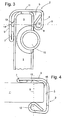
- FIG. 2 shows a side view of the upper portion of the decorative plate.
- the upper edge region above the higher of the two pins 10 forms a spring 5, which in a groove of the profile element 2 engages.
- the profile element is formed from a strip-shaped blank, for example made of aluminum or stainless steel sheet, in which both sides of a central portion 11 two edge strips are bent approximately at right angles to form the spring 5 on both sides embracing legs 3, 4, wherein the outermost edge zones the legs are in turn bent back into the interior of the groove 6 and thus form projections directed into the groove 6.
- the length of the two legs is unequal.
- FIG. 4 shows in a side view analogous to FIG. 3 the same profile element 2, mounted on the edge of a glass plate 1 ', for example, a refrigerated goods carrier, which is provided for mounting in the interior of a refrigerator. Since it is complicated in such a glass plate 1 ', the one piece forming the longer leg 3 of the profile element 2 touching rib 13 with the plate, it is here realized by a plastic profile which is glued to the plate 1' over the entire surface.
- the plastic profile comprises in addition to the actual rib 13 to the front edge of the plate 1 'down pulled tongue 15 of small thickness, which prevents the attachment of the profile element 2 on the plate 1' that the bond between the rib 13 and the plate 1 'under the Pressure of the projection 7 of the leg 3 against the rib 13 detaches and the rib 13 is moved or demolished.
Landscapes
- Engineering & Computer Science (AREA)
- General Engineering & Computer Science (AREA)
- Mechanical Engineering (AREA)
- Chemical & Material Sciences (AREA)
- Combustion & Propulsion (AREA)
- Physics & Mathematics (AREA)
- Thermal Sciences (AREA)
- Refrigerator Housings (AREA)
- Connection Of Plates (AREA)
- Springs (AREA)
Description
- Die vorliegende Erfindung betrifft ein Kältegerät mit einer Steckverbindung zwischen zwei Profilelementen, einem eine Feder aufweisende ersten Element und einem eine Nut zum Aufnehmen der Feder aufweisenden zweiten Element. Bei dem ersten Element kann es sich beispielsweise um eine Platte handeln, deren Rand die Feder bildet, und das zweite Elemente ist ein Profil, das auf den Rand der Platte aufgesteckt wird, um diesen vor Beschädigung zu schützen.
- Um eine feste Klemmung der Elemente zu gewährleisten, auch wenn die Dicke der Feder und die Breite der Nut innerhalb gewisser Toleranzen streuen, ist es üblich, die Nut geringfügig breiter zu machen, als es der Dicke der Feder entspricht, und an den Schenkeln der Nut, in einer Entfernung von ihrem Boden, in die Nut hinein gerichtete Vorsprünge vorzusehen, die unter elastischer Verformung der Schenkel die Feder einklemmen. Wenn der Abstand dieser Vorsprünge vom Boden der Nut nicht identisch ist, ergibt sich das Problem, dass die zwei Elemente in Bezug aufeinander zum Verkippen neigen.
- Dies ist in
Figur 1 veranschaulicht. Hier ist auf eine Platte 21 ein Profilelement 2 mit U-ähnlichem Querschnitt aufgesteckt. Das Profilelement ist in zwei Orientierungen, mit 22 beziehungsweise 22' bezeichnet, dargestellt, wobei 22 eine gewünschte Orientierung und 22' eine Orientierung ist, die sich tatsächlich einstellt. Das Profilelement hat zwei ungleich lange Schenkel 23, 24, die einen als Feder 25 fungierenden Randbereich der Platte 21 einklemmen. Dabei sind in die Nut 26 hinein gerichtete Vorsprünge jeweils durch umgebogene Randabschnitte 27, 28 an den freien Enden der Schenkel 23, 24 gebildet. Diese Vorsprünge berühren die Feder 25 jeweils in unterschiedlichen Abständen vom Boden der Nut 6 beziehungsweise der Oberkante der Feder 25. Eine die Kontaktpunkte zwischen dem Profilelement 22 und der Platte 21 auf beiden Seiten der Feder 25 verbindende Ebene ist in der Figur als strichpunktierte Linie eingezeichnet, die für die mit 22 bezeichnete gewünschte Position des Profilelements mit 29, für die sich tatsächlich einstellende Position 22' mit 29' bezeichnet ist. Wie man leicht sieht, ist der Abstand zwischen den Kontaktpunkten auf der Ebene 29' deutlich kürzer als auf der Ebene 29, das heißt die elastische Verbiegung der Schenkel 3 durch den Druck, den diese auf die Feder 25 ausüben, ist in der Orientierung 22' geringer. - Aufgabe der Erfindung ist, ein Kältegerät mit einer Steckverbindung anzugeben, bei der keine unerwünschte Verkippung des die Feder aufweisenden Elements und des die Nut aufweisenden Elements in Bezug zueinander auftritt.
- Die Aufgabe wird gelöst durch ein Kältegerät mit einer Steckverbindung mit den Merkmalen des Anspruchs 1.
- Indem die Feder mit einem einem der Schenkel zugewandten Vorsprung oder der Schenkel mit einem der Feder zugewandten Vorsprung versehen ist und die Kontaktpunkte zwischen dem Vorsprung des jeweils anderen Schenkels und der Feder einerseits und zwischen dem Vorsprung der Feder und dem einen Schenkel bzw. dem Vorsprung dieses Schenkels und der Feder andererseits eine Ebene definieren, die auf den sich an den Kontaktpunkten berührenden Oberflächen der Schenkel und der Feder senkrecht steht, ist gewährleistet, dass die Entfernung zwischen den Kontaktpunkten beiderseits der Feder minimal ist, so dass eine Verkippung der zwei Elemente gegeneinander nicht zu einer Entspannung der biegebelasteten Schenkel führen kann. Dadurch ist die Orientierung der Elemente der Steckverbindung gegeneinander stabilisiert. Ein an der Feder angeordneter Vorsprung hat darüber hinaus den Vorteil, dass der Schenkel des U-profilartigen Steckelements an seiner Schenkelfläche frei von Unterbrechungen ist und damit das Steckelement einfach herzustellen ist.
- Um die Ebene der Kontaktpunkte zu definieren, genügen minimal drei Kontaktpunkte auf unterschiedlichen Seiten der Feder. Vorzugsweise bilden allerdings die Kontaktpunkte auf wenigstens einer Seite der Feder eine Linie.
- Das die Nut aufweisende Element ist vorzugsweise aus einem Flachmaterial, etwa einem Metallstreifen geformt, und der Vorsprung des einen Schenkels ist durch einen in die Nut zurückgebogenen Randabschnitt des Flachmaterials gebildet. So verschwinden eventuelle scharfe Kanten, die beim Zuschneiden des Flachmaterials entstehen, im Innern der Nut, so dass sie einen Benutzer nicht gefährden können.
- Aus dem gleichen Grund ist vorzugsweise auch der zweite Schenkel mit einem in die Nut zurückgebogenen Randabschnitt versehen.
- Die Feder ist vorzugsweise mit ihrem Vorsprung einteilig ausgebildet. Dies ist insbesondere bei einem die Feder aufweisenden Element aus Kunststoff leicht realisierbar. Wenn es sich bei dem die Feder aufweisenden Element zum Beispiel um eine Glasplatte handelt, könnte der Vorsprung auch mit der Platte zweiteilig ausgeführt, zum Beispiel aufgeklebt sein.
- Weitere Merkmale und Vorteile der Erfindung ergeben sich aus der nachfolgenden Beschreibung von Ausführungsbeispielen unter Bezugnahme auf die beigefügten Figuren. Es zeigen:
- Figur 1
- bereits behandelt, eine Seitenansicht einer Platte, auf deren Rand ein Profilelement in herkömmlicher Weise aufgesteckt ist;
- Figur 2
- eine perspektivische Ansicht einer Dekorplatte eines Türabstellers für ein Kältegerät als Anwendungsbeispiel der Erfindung;
- Figur 3
- eine Seitenansicht der Dekorplatte aus
Figur 2 ; und - Figur 4
- eine Seitenansicht eines Randbereichs eines Kühlgutträgers gemäß der Erfindung.
- Die in
Figur 2 in perspektivischer Ansicht gezeigte Dekorplatte setzt sich zusammen aus einer aus einem Kunststoffmaterial gespritzten Platte 1, auf deren oberen Rand ein aus Blech gebogenes Profilelement 2 unter elastischer Verformung aufgesteckt ist. Die Dekorplatte ist vorgesehen, um einen Teil einer Längswand eines Türabstellers zu bilden, der zum Aufnehmen von Kühlgut an der Innenseite einer Tür eines Kühlschranks oder anderen Kältegeräts montiert ist. An den Längsrändern der Platte 1 gebildete Zapfen 10 dienen zur Verankerung der Dekorplatte in einem Randausschnitt des Türabstellers. -
Figur 2 zeigt eine Seitenansicht des oberen Bereichs der Dekorplatte. Deren oberer Randbereich oberhalb des höher gelegenen der zwei Zapfen 10 bildet eine Feder 5, die in eine Nut des Profilelements 2 eingreift. Das Profilelement ist aus einem streifenförmigen Zuschnitt, zum Beispiel aus Aluminium- oder Edelstahlblech, gebildet, in dem beiderseits eines zentralen Abschnitts 11 zwei Randstreifen in etwa rechtwinklig abgebogen sind, um die Feder 5 beidseitig umgreifende Schenkel 3, 4 zu bilden, wobei die äußersten Randzonen der Schenkel wiederum ins Innere der Nut 6 zurückgebogen sind und so in die Nut 6 hinein gerichtete Vorsprünge bilden. Die Länge der zwei Schenkel ist ungleich. - In Höhe einer Kontaktlinie aus Kontaktpunkten 12, die sich zwischen dem Vorsprung 8 des kürzeren Schenkels 4 und der Feder 5 senkrecht zur Ebene der
Figur 3 erstreckt, ist an der dem längeren Schenkel 3 zugewandten Seite der Feder 5 eine sich ebenfalls senkrecht zur Ebene der Figur erstreckende Rippe 13 gebildet, deren Spitze den Schenkel 3 entlang einer zweiten Kontaktlinie aus Kontaktpunkten 14 berührt. Die sich an den Kontaktlinien aus Kontaktpunkten 12, 14 berührenden Oberflächen der Feder 5 und des Profilelements 2 stehen senkrecht auf der durch die Linien aus Kontaktpunkten 12, 14 definierten Klemmebene 9. Jede Verkippung des Profilelements 2 um eine zur Ebene derFigur 3 senkrechte Achse würde daher zu einer Vergrößerung des Abstandes zwischen den Kontaktlinien aus Kontaktpunkten 12, 14 und infolge dessen zu einem Auseinanderspreizen der Schenkel 3, 4 führen. Die dargestellte Orientierung des Profilelements 2 zur Platte 1 ist daher stabil. -
Figur 4 zeigt in einer Seitenansicht analog derFigur 3 das gleiche Profilelement 2, aufgesteckt auf den Rand einer Glasplatte 1', beispielsweise eines Kühlgutträgers, der zur Montage im Innenraum eines Kühlschranks vorgesehen ist. Da es bei einer solchen Glasplatte 1' aufwändig ist, die den längeren Schenkel 3 der Profilelements 2 berührende Rippe 13 mit der Platte einteilig auszubilden, ist sie hier durch ein Kunststoffprofil realisiert, das auf die Platte 1' vollflächig aufgeklebt ist. Das Kunststoffprofil umfasst neben der eigentlichen Rippe 13 eine zur Vorderkante der Platte 1' hin gezogene Zunge 15 geringer Dicke, die beim Aufstecken des Profilelements 2 auf die Platte 1' verhindert, dass sich die Klebung zwischen der Rippe 13 und der Platte 1' unter dem Druck des Vorsprungs 7 des Schenkels 3 gegen die Rippe 13 ablöst und die Rippe 13 verschoben oder abgerissen wird.
Claims (6)
- Kältegerät mit einer Steckverbindung mit einem eine Feder (5) aufweisenden ersten Element (1, 1'), welches ein Innenteil eines Kältegeräts wie etwa ein Türabsteller, ein Auszugkasten oder ein Fachboden ist, und einem eine Nut (6) zum Aufnehmen der Feder (5) aufweisenden zweiten Element (2), wobei die Nut (6) von einem Boden und zwei Schenkeln (3,4) begrenzt ist und wenigstens ein erster der Schenkel (4) einen ins Innere der Nut (6) eindringenden Vorsprung (8) aufweist, dadurch gekennzeichnet, dass die Feder (5) einen dem zweiten Schenkel (3) zugewandten Vorsprung (13) oder der zweite Schenkel (3) einen der Feder (5) zugewandten Vorsprung (13) aufweist, und dass Kontaktpunkte (12) zwischen dem Vorsprung (8) des ersten Schenkels (4) und der Feder (5) und/oder Kontaktpunkte (14) zwischen dem Vorsprung (13) der Feder (5) und dem zweiten Schenkel (3) bzw. dem Vorsprung (13) am zweiten Schenkel (3) und der Feder (5) eine Linie bilden und dass die Kontaktpunkte (12, 14) zwischen dem Vorsprung (8) des ersten Schenkels (4) und der Feder (5) einerseits und zwischen dem Vorsprung (13) der Feder (5) und dem zweiten Schenkel (3) bzw. dem Vorsprung (13) am zweiten Schenkel (3) und der Feder (5) andererseits eine Ebene (9) definieren, die auf den sich an den Kontaktpunkten (12, 14) berührenden Oberflächen der Schenkel (3, 4) und der Feder (5) senkrecht steht.
- Kältegerät mit einer Steckverbindung nach Anspruch 1, dadurch gekennzeichnet, dass das die Nut (6) aufweisende Element (2) aus Flachmaterial geformt ist, und dass der Vorsprung (8) des ersten Schenkels (4) durch einen in die Nut zurückgebogenen Randabschnitt des Flachmaterials gebildet ist.
- Kältegerät mit einer Steckverbindung nach Anspruch 2, dadurch gekennzeichnet, dass auch der zweite Schenkel (3) einen in die Nut (6) zurückgebogenen Randabschnitt aufweist.
- Kältegerät mit einer Steckverbindung nach Anspruch 1 oder 2, dadurch gekennzeichnet, dass das die Nut (6) aufweisende Element (2) federnde Eigenschaften aufweist.
- Kältegerät mit einer Steckverbindung nach einem der Ansprüche 1 bis 4, dadurch gekennzeichnet, dass die Feder (5) mit ihrem Vorsprung (13) einteilig ausgebildet ist.
- Kältegerät mit einer Steckverbindung nach einem der Ansprüche 1 bis 4, dadurch gekennzeichnet, dass der sich an der Feder (5) abstützende Vorsprung (13) am zweiten Schenkel (3) durch spanlose Formgebung des zweiten Schenkel (3) erzielt ist.
Applications Claiming Priority (2)
| Application Number | Priority Date | Filing Date | Title |
|---|---|---|---|
| DE20313198U DE20313198U1 (de) | 2003-08-26 | 2003-08-26 | Steckverbindung |
| DE20313198U | 2003-08-26 |
Publications (2)
| Publication Number | Publication Date |
|---|---|
| EP1510703A1 EP1510703A1 (de) | 2005-03-02 |
| EP1510703B1 true EP1510703B1 (de) | 2014-02-26 |
Family
ID=29285993
Family Applications (1)
| Application Number | Title | Priority Date | Filing Date |
|---|---|---|---|
| EP04019862.4A Expired - Lifetime EP1510703B1 (de) | 2003-08-26 | 2004-08-20 | Steckverbindung |
Country Status (3)
| Country | Link |
|---|---|
| EP (1) | EP1510703B1 (de) |
| DE (1) | DE20313198U1 (de) |
| ES (1) | ES2450132T3 (de) |
Families Citing this family (2)
| Publication number | Priority date | Publication date | Assignee | Title |
|---|---|---|---|---|
| DE10208058B4 (de) | 2002-02-25 | 2018-10-25 | BSH Hausgeräte GmbH | Kältegerät |
| DE20313198U1 (de) * | 2003-08-26 | 2003-10-23 | BSH Bosch und Siemens Hausgeräte GmbH, 81669 München | Steckverbindung |
Citations (1)
| Publication number | Priority date | Publication date | Assignee | Title |
|---|---|---|---|---|
| EP1510703A1 (de) * | 2003-08-26 | 2005-03-02 | BSH Bosch und Siemens Hausgeräte GmbH | Steckverbindung |
Family Cites Families (3)
| Publication number | Priority date | Publication date | Assignee | Title |
|---|---|---|---|---|
| US3382615A (en) * | 1966-03-04 | 1968-05-14 | Adell Robert | Ornamental and protective molding for motor vehicle doors |
| US3984163A (en) * | 1975-12-22 | 1976-10-05 | General Electric Company | Cantilever sliding shelf including a shelf removal notch on one side only |
| US5040856A (en) * | 1987-02-27 | 1991-08-20 | Sub-Zero Freezer Company, Inc. | Comestible storage compartment for refrigeration unit |
-
2003
- 2003-08-26 DE DE20313198U patent/DE20313198U1/de not_active Expired - Lifetime
-
2004
- 2004-08-20 EP EP04019862.4A patent/EP1510703B1/de not_active Expired - Lifetime
- 2004-08-20 ES ES04019862T patent/ES2450132T3/es not_active Expired - Lifetime
Patent Citations (1)
| Publication number | Priority date | Publication date | Assignee | Title |
|---|---|---|---|---|
| EP1510703A1 (de) * | 2003-08-26 | 2005-03-02 | BSH Bosch und Siemens Hausgeräte GmbH | Steckverbindung |
Also Published As
| Publication number | Publication date |
|---|---|
| ES2450132T3 (es) | 2014-03-24 |
| DE20313198U1 (de) | 2003-10-23 |
| EP1510703A1 (de) | 2005-03-02 |
Similar Documents
| Publication | Publication Date | Title |
|---|---|---|
| DE60203982T2 (de) | Etikettenträger zur Befestigung an einem schmalkantigen Regal | |
| EP2457043B1 (de) | Höhenverstellbarer kühlgutträger | |
| EP1985204B1 (de) | Steckprofilelement | |
| EP2122278A2 (de) | Kältegerät mit an einer schiene aufgehängten fachböden | |
| DE8232893U1 (de) | Einstueckiges streifenprofil | |
| EP1882137B1 (de) | Tür für ein haushaltsgerät | |
| AT405712B (de) | Schubladen-seitenwandprofil aus metall | |
| WO2008122490A1 (de) | Eierträger | |
| AT393601B (de) | Schublade | |
| EP2642896B1 (de) | Behältnisschiene für einen schubladenbehälter | |
| EP2443405A2 (de) | Schrankartiges haushaltsgerät mit fachboden | |
| EP1481209B1 (de) | Randabschlussteil für eine glasplatte | |
| EP1510703A1 (de) | Steckverbindung | |
| EP2300677B1 (de) | Scharniertopf für möbelscharniere | |
| AT393600B (de) | Schublade | |
| EP2603750B1 (de) | Ein kühlgerät mit einem regaltrennelement | |
| DE3200282C2 (de) | ||
| AT520804A1 (de) | Doppelwandige Schubladenseitenwand | |
| DE102008054498A1 (de) | Gehäuse für ein Haushaltsgerät | |
| DE69603522T2 (de) | Dekoratives Teil aus Kunststoff | |
| DE19607935C2 (de) | Befestigungsvorrichtung für Sockelblenden | |
| DE20215552U1 (de) | Träger für ein Regal | |
| DE19860434A1 (de) | Käfigmutter mit einem Käfig und einer Mutter | |
| EP2980513A1 (de) | Kühlgutablage für ein kältegerät | |
| DE19929144B4 (de) | Buchstütze |
Legal Events
| Date | Code | Title | Description |
|---|---|---|---|
| PUAI | Public reference made under article 153(3) epc to a published international application that has entered the european phase |
Free format text: ORIGINAL CODE: 0009012 |
|
| AK | Designated contracting states |
Kind code of ref document: A1 Designated state(s): AT BE BG CH CY CZ DE DK EE ES FI FR GB GR HU IE IT LI LU MC NL PL PT RO SE SI SK TR |
|
| AX | Request for extension of the european patent |
Extension state: AL HR LT LV MK |
|
| 17P | Request for examination filed |
Effective date: 20050902 |
|
| AKX | Designation fees paid |
Designated state(s): AT BE BG CH CY CZ DE DK EE ES FI FR GB GR HU IE IT LI LU MC NL PL PT RO SE SI SK TR |
|
| 17Q | First examination report despatched |
Effective date: 20060203 |
|
| APBK | Appeal reference recorded |
Free format text: ORIGINAL CODE: EPIDOSNREFNE |
|
| APBN | Date of receipt of notice of appeal recorded |
Free format text: ORIGINAL CODE: EPIDOSNNOA2E |
|
| APBR | Date of receipt of statement of grounds of appeal recorded |
Free format text: ORIGINAL CODE: EPIDOSNNOA3E |
|
| APAF | Appeal reference modified |
Free format text: ORIGINAL CODE: EPIDOSCREFNE |
|
| APBT | Appeal procedure closed |
Free format text: ORIGINAL CODE: EPIDOSNNOA9E |
|
| GRAP | Despatch of communication of intention to grant a patent |
Free format text: ORIGINAL CODE: EPIDOSNIGR1 |
|
| INTG | Intention to grant announced |
Effective date: 20131007 |
|
| RIC1 | Information provided on ipc code assigned before grant |
Ipc: F25D 23/04 20060101ALI20130930BHEP Ipc: F16B 5/12 20060101AFI20130930BHEP |
|
| GRAS | Grant fee paid |
Free format text: ORIGINAL CODE: EPIDOSNIGR3 |
|
| GRAA | (expected) grant |
Free format text: ORIGINAL CODE: 0009210 |
|
| AK | Designated contracting states |
Kind code of ref document: B1 Designated state(s): AT BE BG CH CY CZ DE DK EE ES FI FR GB GR HU IE IT LI LU MC NL PL PT RO SE SI SK TR |
|
| REG | Reference to a national code |
Ref country code: GB Ref legal event code: FG4D Free format text: NOT ENGLISH |
|
| REG | Reference to a national code |
Ref country code: CH Ref legal event code: EP |
|
| REG | Reference to a national code |
Ref country code: AT Ref legal event code: REF Ref document number: 653791 Country of ref document: AT Kind code of ref document: T Effective date: 20140315 |
|
| REG | Reference to a national code |
Ref country code: ES Ref legal event code: FG2A Ref document number: 2450132 Country of ref document: ES Kind code of ref document: T3 Effective date: 20140324 |
|
| REG | Reference to a national code |
Ref country code: IE Ref legal event code: FG4D Free format text: LANGUAGE OF EP DOCUMENT: GERMAN |
|
| REG | Reference to a national code |
Ref country code: DE Ref legal event code: R096 Ref document number: 502004014525 Country of ref document: DE Effective date: 20140410 |
|
| REG | Reference to a national code |
Ref country code: NL Ref legal event code: VDEP Effective date: 20140226 |
|
| PG25 | Lapsed in a contracting state [announced via postgrant information from national office to epo] |
Ref country code: CY Free format text: LAPSE BECAUSE OF FAILURE TO SUBMIT A TRANSLATION OF THE DESCRIPTION OR TO PAY THE FEE WITHIN THE PRESCRIBED TIME-LIMIT Effective date: 20140226 Ref country code: PT Free format text: LAPSE BECAUSE OF FAILURE TO SUBMIT A TRANSLATION OF THE DESCRIPTION OR TO PAY THE FEE WITHIN THE PRESCRIBED TIME-LIMIT Effective date: 20140626 Ref country code: NL Free format text: LAPSE BECAUSE OF FAILURE TO SUBMIT A TRANSLATION OF THE DESCRIPTION OR TO PAY THE FEE WITHIN THE PRESCRIBED TIME-LIMIT Effective date: 20140226 Ref country code: FI Free format text: LAPSE BECAUSE OF FAILURE TO SUBMIT A TRANSLATION OF THE DESCRIPTION OR TO PAY THE FEE WITHIN THE PRESCRIBED TIME-LIMIT Effective date: 20140226 Ref country code: SE Free format text: LAPSE BECAUSE OF FAILURE TO SUBMIT A TRANSLATION OF THE DESCRIPTION OR TO PAY THE FEE WITHIN THE PRESCRIBED TIME-LIMIT Effective date: 20140226 |
|
| PG25 | Lapsed in a contracting state [announced via postgrant information from national office to epo] |
Ref country code: CZ Free format text: LAPSE BECAUSE OF FAILURE TO SUBMIT A TRANSLATION OF THE DESCRIPTION OR TO PAY THE FEE WITHIN THE PRESCRIBED TIME-LIMIT Effective date: 20140226 Ref country code: EE Free format text: LAPSE BECAUSE OF FAILURE TO SUBMIT A TRANSLATION OF THE DESCRIPTION OR TO PAY THE FEE WITHIN THE PRESCRIBED TIME-LIMIT Effective date: 20140226 Ref country code: RO Free format text: LAPSE BECAUSE OF FAILURE TO SUBMIT A TRANSLATION OF THE DESCRIPTION OR TO PAY THE FEE WITHIN THE PRESCRIBED TIME-LIMIT Effective date: 20140226 Ref country code: DK Free format text: LAPSE BECAUSE OF FAILURE TO SUBMIT A TRANSLATION OF THE DESCRIPTION OR TO PAY THE FEE WITHIN THE PRESCRIBED TIME-LIMIT Effective date: 20140226 |
|
| REG | Reference to a national code |
Ref country code: DE Ref legal event code: R097 Ref document number: 502004014525 Country of ref document: DE |
|
| PG25 | Lapsed in a contracting state [announced via postgrant information from national office to epo] |
Ref country code: SK Free format text: LAPSE BECAUSE OF FAILURE TO SUBMIT A TRANSLATION OF THE DESCRIPTION OR TO PAY THE FEE WITHIN THE PRESCRIBED TIME-LIMIT Effective date: 20140226 Ref country code: PL Free format text: LAPSE BECAUSE OF FAILURE TO SUBMIT A TRANSLATION OF THE DESCRIPTION OR TO PAY THE FEE WITHIN THE PRESCRIBED TIME-LIMIT Effective date: 20140226 |
|
| PLBE | No opposition filed within time limit |
Free format text: ORIGINAL CODE: 0009261 |
|
| STAA | Information on the status of an ep patent application or granted ep patent |
Free format text: STATUS: NO OPPOSITION FILED WITHIN TIME LIMIT |
|
| 26N | No opposition filed |
Effective date: 20141127 |
|
| REG | Reference to a national code |
Ref country code: CH Ref legal event code: PFA Owner name: BSH HAUSGERAETE GMBH, DE Free format text: FORMER OWNER: BSH BOSCH UND SIEMENS HAUSGERAETE GMBH, DE |
|
| REG | Reference to a national code |
Ref country code: DE Ref legal event code: R097 Ref document number: 502004014525 Country of ref document: DE Effective date: 20141127 |
|
| PG25 | Lapsed in a contracting state [announced via postgrant information from national office to epo] |
Ref country code: IT Free format text: LAPSE BECAUSE OF FAILURE TO SUBMIT A TRANSLATION OF THE DESCRIPTION OR TO PAY THE FEE WITHIN THE PRESCRIBED TIME-LIMIT Effective date: 20140226 Ref country code: MC Free format text: LAPSE BECAUSE OF FAILURE TO SUBMIT A TRANSLATION OF THE DESCRIPTION OR TO PAY THE FEE WITHIN THE PRESCRIBED TIME-LIMIT Effective date: 20140226 Ref country code: LU Free format text: LAPSE BECAUSE OF FAILURE TO SUBMIT A TRANSLATION OF THE DESCRIPTION OR TO PAY THE FEE WITHIN THE PRESCRIBED TIME-LIMIT Effective date: 20140820 |
|
| REG | Reference to a national code |
Ref country code: CH Ref legal event code: PL |
|
| PG25 | Lapsed in a contracting state [announced via postgrant information from national office to epo] |
Ref country code: BE Free format text: LAPSE BECAUSE OF NON-PAYMENT OF DUE FEES Effective date: 20140831 Ref country code: LI Free format text: LAPSE BECAUSE OF NON-PAYMENT OF DUE FEES Effective date: 20140831 Ref country code: CH Free format text: LAPSE BECAUSE OF NON-PAYMENT OF DUE FEES Effective date: 20140831 |
|
| REG | Reference to a national code |
Ref country code: DE Ref legal event code: R081 Ref document number: 502004014525 Country of ref document: DE Owner name: BSH HAUSGERAETE GMBH, DE Free format text: FORMER OWNER: BSH BOSCH UND SIEMENS HAUSGERAETE GMBH, 81739 MUENCHEN, DE Effective date: 20150407 Ref country code: DE Ref legal event code: R081 Ref document number: 502004014525 Country of ref document: DE Owner name: BSH HAUSGERAETE GMBH, DE Free format text: FORMER OWNER: BSH BOSCH UND SIEMENS HAUSGERAETE GMBH, 81739 MUENCHEN, DE Effective date: 20140228 |
|
| REG | Reference to a national code |
Ref country code: IE Ref legal event code: MM4A |
|
| PG25 | Lapsed in a contracting state [announced via postgrant information from national office to epo] |
Ref country code: SI Free format text: LAPSE BECAUSE OF FAILURE TO SUBMIT A TRANSLATION OF THE DESCRIPTION OR TO PAY THE FEE WITHIN THE PRESCRIBED TIME-LIMIT Effective date: 20140226 |
|
| REG | Reference to a national code |
Ref country code: FR Ref legal event code: ST Effective date: 20150430 |
|
| REG | Reference to a national code |
Ref country code: ES Ref legal event code: PC2A Owner name: BSH HAUSGERATE GMBH Effective date: 20150527 |
|
| PG25 | Lapsed in a contracting state [announced via postgrant information from national office to epo] |
Ref country code: IE Free format text: LAPSE BECAUSE OF NON-PAYMENT OF DUE FEES Effective date: 20140820 Ref country code: FR Free format text: LAPSE BECAUSE OF NON-PAYMENT OF DUE FEES Effective date: 20140901 |
|
| REG | Reference to a national code |
Ref country code: AT Ref legal event code: MM01 Ref document number: 653791 Country of ref document: AT Kind code of ref document: T Effective date: 20140820 |
|
| PG25 | Lapsed in a contracting state [announced via postgrant information from national office to epo] |
Ref country code: AT Free format text: LAPSE BECAUSE OF NON-PAYMENT OF DUE FEES Effective date: 20140820 |
|
| PG25 | Lapsed in a contracting state [announced via postgrant information from national office to epo] |
Ref country code: BG Free format text: LAPSE BECAUSE OF FAILURE TO SUBMIT A TRANSLATION OF THE DESCRIPTION OR TO PAY THE FEE WITHIN THE PRESCRIBED TIME-LIMIT Effective date: 20140226 |
|
| PG25 | Lapsed in a contracting state [announced via postgrant information from national office to epo] |
Ref country code: GR Free format text: LAPSE BECAUSE OF FAILURE TO SUBMIT A TRANSLATION OF THE DESCRIPTION OR TO PAY THE FEE WITHIN THE PRESCRIBED TIME-LIMIT Effective date: 20140527 |
|
| PG25 | Lapsed in a contracting state [announced via postgrant information from national office to epo] |
Ref country code: HU Free format text: LAPSE BECAUSE OF FAILURE TO SUBMIT A TRANSLATION OF THE DESCRIPTION OR TO PAY THE FEE WITHIN THE PRESCRIBED TIME-LIMIT; INVALID AB INITIO Effective date: 20040820 |
|
| PGFP | Annual fee paid to national office [announced via postgrant information from national office to epo] |
Ref country code: GB Payment date: 20160824 Year of fee payment: 13 |
|
| PGFP | Annual fee paid to national office [announced via postgrant information from national office to epo] |
Ref country code: ES Payment date: 20160829 Year of fee payment: 13 |
|
| PGFP | Annual fee paid to national office [announced via postgrant information from national office to epo] |
Ref country code: DE Payment date: 20170831 Year of fee payment: 14 |
|
| PGFP | Annual fee paid to national office [announced via postgrant information from national office to epo] |
Ref country code: TR Payment date: 20170816 Year of fee payment: 14 |
|
| GBPC | Gb: european patent ceased through non-payment of renewal fee |
Effective date: 20170820 |
|
| PG25 | Lapsed in a contracting state [announced via postgrant information from national office to epo] |
Ref country code: GB Free format text: LAPSE BECAUSE OF NON-PAYMENT OF DUE FEES Effective date: 20170820 |
|
| REG | Reference to a national code |
Ref country code: ES Ref legal event code: FD2A Effective date: 20181029 |
|
| PG25 | Lapsed in a contracting state [announced via postgrant information from national office to epo] |
Ref country code: ES Free format text: LAPSE BECAUSE OF NON-PAYMENT OF DUE FEES Effective date: 20170821 |
|
| REG | Reference to a national code |
Ref country code: DE Ref legal event code: R119 Ref document number: 502004014525 Country of ref document: DE |
|
| PG25 | Lapsed in a contracting state [announced via postgrant information from national office to epo] |
Ref country code: DE Free format text: LAPSE BECAUSE OF NON-PAYMENT OF DUE FEES Effective date: 20190301 |
|
| PG25 | Lapsed in a contracting state [announced via postgrant information from national office to epo] |
Ref country code: TR Free format text: LAPSE BECAUSE OF NON-PAYMENT OF DUE FEES Effective date: 20180820 |