EP1510328A2 - Integrierte Vorrichtung und Verfahren zur Füllung von porösen Vorformlingen aus Verbundwerkstoffen - Google Patents
Integrierte Vorrichtung und Verfahren zur Füllung von porösen Vorformlingen aus Verbundwerkstoffen Download PDFInfo
- Publication number
- EP1510328A2 EP1510328A2 EP04255147A EP04255147A EP1510328A2 EP 1510328 A2 EP1510328 A2 EP 1510328A2 EP 04255147 A EP04255147 A EP 04255147A EP 04255147 A EP04255147 A EP 04255147A EP 1510328 A2 EP1510328 A2 EP 1510328A2
- Authority
- EP
- European Patent Office
- Prior art keywords
- autoclave
- tank
- slurry
- pressure
- vacuum
- Prior art date
- Legal status (The legal status is an assumption and is not a legal conclusion. Google has not performed a legal analysis and makes no representation as to the accuracy of the status listed.)
- Withdrawn
Links
- 238000000034 method Methods 0.000 title claims abstract description 43
- 238000011049 filling Methods 0.000 title claims abstract description 10
- 239000002131 composite material Substances 0.000 title description 4
- 239000002002 slurry Substances 0.000 claims abstract description 81
- 239000011347 resin Substances 0.000 claims abstract description 25
- 229920005989 resin Polymers 0.000 claims abstract description 25
- 238000012546 transfer Methods 0.000 claims abstract description 25
- 230000005484 gravity Effects 0.000 claims abstract description 5
- 238000005266 casting Methods 0.000 claims abstract 12
- 239000000463 material Substances 0.000 claims description 13
- 238000012544 monitoring process Methods 0.000 claims description 2
- 230000008569 process Effects 0.000 description 37
- QVGXLLKOCUKJST-UHFFFAOYSA-N atomic oxygen Chemical compound [O] QVGXLLKOCUKJST-UHFFFAOYSA-N 0.000 description 16
- 229910052760 oxygen Inorganic materials 0.000 description 16
- 239000001301 oxygen Substances 0.000 description 16
- IJGRMHOSHXDMSA-UHFFFAOYSA-N Atomic nitrogen Chemical compound N#N IJGRMHOSHXDMSA-UHFFFAOYSA-N 0.000 description 12
- 238000010438 heat treatment Methods 0.000 description 8
- 238000002360 preparation method Methods 0.000 description 8
- 239000012298 atmosphere Substances 0.000 description 6
- 238000002156 mixing Methods 0.000 description 6
- 229910052757 nitrogen Inorganic materials 0.000 description 6
- 238000012545 processing Methods 0.000 description 6
- 238000010125 resin casting Methods 0.000 description 6
- 238000007582 slurry-cast process Methods 0.000 description 6
- 238000002485 combustion reaction Methods 0.000 description 4
- 230000008859 change Effects 0.000 description 3
- 238000007872 degassing Methods 0.000 description 3
- 229920000642 polymer Polymers 0.000 description 3
- 239000010935 stainless steel Substances 0.000 description 3
- 229910001220 stainless steel Inorganic materials 0.000 description 3
- 238000013022 venting Methods 0.000 description 3
- 210000004556 brain Anatomy 0.000 description 2
- 150000001875 compounds Chemical class 0.000 description 2
- 239000011521 glass Substances 0.000 description 2
- 239000012299 nitrogen atmosphere Substances 0.000 description 2
- 238000010926 purge Methods 0.000 description 2
- 238000005096 rolling process Methods 0.000 description 2
- 230000007704 transition Effects 0.000 description 2
- 229910000975 Carbon steel Inorganic materials 0.000 description 1
- 238000004458 analytical method Methods 0.000 description 1
- 230000033228 biological regulation Effects 0.000 description 1
- 230000005540 biological transmission Effects 0.000 description 1
- 230000000740 bleeding effect Effects 0.000 description 1
- 239000010962 carbon steel Substances 0.000 description 1
- 238000010586 diagram Methods 0.000 description 1
- 238000001035 drying Methods 0.000 description 1
- 230000000694 effects Effects 0.000 description 1
- 239000000835 fiber Substances 0.000 description 1
- 239000000446 fuel Substances 0.000 description 1
- 230000008570 general process Effects 0.000 description 1
- 239000003365 glass fiber Substances 0.000 description 1
- 238000005286 illumination Methods 0.000 description 1
- 230000006698 induction Effects 0.000 description 1
- 230000007246 mechanism Effects 0.000 description 1
- 239000000203 mixture Substances 0.000 description 1
- 210000003254 palate Anatomy 0.000 description 1
- 238000010951 particle size reduction Methods 0.000 description 1
- 229920001084 poly(chloroprene) Polymers 0.000 description 1
- 230000002028 premature Effects 0.000 description 1
- 238000011112 process operation Methods 0.000 description 1
- 238000005086 pumping Methods 0.000 description 1
- 239000002994 raw material Substances 0.000 description 1
- 238000004064 recycling Methods 0.000 description 1
- 230000001105 regulatory effect Effects 0.000 description 1
- 238000012163 sequencing technique Methods 0.000 description 1
- 238000003756 stirring Methods 0.000 description 1
- XLYOFNOQVPJJNP-UHFFFAOYSA-N water Substances O XLYOFNOQVPJJNP-UHFFFAOYSA-N 0.000 description 1
- 239000012856 weighed raw material Substances 0.000 description 1
Images


Classifications
-
- B—PERFORMING OPERATIONS; TRANSPORTING
- B29—WORKING OF PLASTICS; WORKING OF SUBSTANCES IN A PLASTIC STATE IN GENERAL
- B29C—SHAPING OR JOINING OF PLASTICS; SHAPING OF MATERIAL IN A PLASTIC STATE, NOT OTHERWISE PROVIDED FOR; AFTER-TREATMENT OF THE SHAPED PRODUCTS, e.g. REPAIRING
- B29C70/00—Shaping composites, i.e. plastics material comprising reinforcements, fillers or preformed parts, e.g. inserts
- B29C70/04—Shaping composites, i.e. plastics material comprising reinforcements, fillers or preformed parts, e.g. inserts comprising reinforcements only, e.g. self-reinforcing plastics
- B29C70/28—Shaping operations therefor
- B29C70/30—Shaping by lay-up, i.e. applying fibres, tape or broadsheet on a mould, former or core; Shaping by spray-up, i.e. spraying of fibres on a mould, former or core
- B29C70/36—Shaping by lay-up, i.e. applying fibres, tape or broadsheet on a mould, former or core; Shaping by spray-up, i.e. spraying of fibres on a mould, former or core and impregnating by casting, e.g. vacuum casting
-
- B—PERFORMING OPERATIONS; TRANSPORTING
- B22—CASTING; POWDER METALLURGY
- B22D—CASTING OF METALS; CASTING OF OTHER SUBSTANCES BY THE SAME PROCESSES OR DEVICES
- B22D31/00—Cutting-off surplus material, e.g. gates; Cleaning and working on castings
- B22D31/002—Cleaning, working on castings
- B22D31/005—Sealing or impregnating porous castings
-
- B—PERFORMING OPERATIONS; TRANSPORTING
- B29—WORKING OF PLASTICS; WORKING OF SUBSTANCES IN A PLASTIC STATE IN GENERAL
- B29C—SHAPING OR JOINING OF PLASTICS; SHAPING OF MATERIAL IN A PLASTIC STATE, NOT OTHERWISE PROVIDED FOR; AFTER-TREATMENT OF THE SHAPED PRODUCTS, e.g. REPAIRING
- B29C70/00—Shaping composites, i.e. plastics material comprising reinforcements, fillers or preformed parts, e.g. inserts
- B29C70/04—Shaping composites, i.e. plastics material comprising reinforcements, fillers or preformed parts, e.g. inserts comprising reinforcements only, e.g. self-reinforcing plastics
- B29C70/28—Shaping operations therefor
- B29C70/40—Shaping or impregnating by compression not applied
- B29C70/42—Shaping or impregnating by compression not applied for producing articles of definite length, i.e. discrete articles
- B29C70/46—Shaping or impregnating by compression not applied for producing articles of definite length, i.e. discrete articles using matched moulds, e.g. for deforming sheet moulding compounds [SMC] or prepregs
- B29C70/48—Shaping or impregnating by compression not applied for producing articles of definite length, i.e. discrete articles using matched moulds, e.g. for deforming sheet moulding compounds [SMC] or prepregs and impregnating the reinforcements in the closed mould, e.g. resin transfer moulding [RTM], e.g. by vacuum
-
- B—PERFORMING OPERATIONS; TRANSPORTING
- B29—WORKING OF PLASTICS; WORKING OF SUBSTANCES IN A PLASTIC STATE IN GENERAL
- B29C—SHAPING OR JOINING OF PLASTICS; SHAPING OF MATERIAL IN A PLASTIC STATE, NOT OTHERWISE PROVIDED FOR; AFTER-TREATMENT OF THE SHAPED PRODUCTS, e.g. REPAIRING
- B29C70/00—Shaping composites, i.e. plastics material comprising reinforcements, fillers or preformed parts, e.g. inserts
- B29C70/04—Shaping composites, i.e. plastics material comprising reinforcements, fillers or preformed parts, e.g. inserts comprising reinforcements only, e.g. self-reinforcing plastics
- B29C70/28—Shaping operations therefor
- B29C70/54—Component parts, details or accessories; Auxiliary operations, e.g. feeding or storage of prepregs or SMC after impregnation or during ageing
Definitions
- the present invention is directed to an integrated apparatus and method for filling a porous composite preform with a slurry or resin.
- the present invention involves the provision of and use of three separate chambers interconnected by one common vacuum system.
- a tank holding slurry is preferably disposed above an autoclave with the tank and autoclave being connected to the common vacuum system. With this arrangement, slurry can be easily and efficiently transferred between the tank and autoclave by the use of the vacuum and gravity.
- the uninfiltrated slurry/resin since the uninfiltrated slurry/resin remains viable, it can be drained, again by the vacuum and gravity into a holding tank. The slurry/resin in the holding tank can then be pumped up to the feed tank, but since the vacuum level of all tanks are the same, the slurry/resin has not degraded due to atmospheric effects, nor has it gained entrapped air.
- a similar process is used in the polymer composites industry, whereby polymers are infiltrated into organic fiber or glass fiber preforms.
- a differential vacuum is used to transport polymer from one tank to the other.
- This invention integrates the operations of 1) slurry/resin preparation, 2) preform preparation, 3) slurry/resin transfer to preform, 4) slurry/resin removal from preform, 5) recycling of slurry/resin, 6) initial drying of slurry/resin. It also allows pressure application during preform filling if required.
- the inventive apparatus and method are especially suited for filling turbine shrouds, turbine engine liners, and for other SiC products.
- Figure 1 shows slurry/resin casting system 8 to include autoclave 11, and tank 10, surrounded by platform 13 and access ladder 12. Also shown in Figure 1 is valve palate 14 which provides a centralized location for the valve connections between tank 10, autoclave 11 and other equipment discussed below. As shown in Figure 1, tank 10 and autoclave 11 are integrated into a relatively compact and accessible arrangement.
- the work platform 13 and ladder 12 provide access to tank 10.
- the structure should conform to all applicable OSHA and local building code specifications.
- tank 10 is shown to be interconnected to autoclave 11 and through diaphragm transfer pump 21 to ball mill 20.
- Ball mill 20 is shown to be remotely located, on the other side of a wall, from tank 10 and autoclave 11.
- a vacuum system (not shown) is connected through valves 22 and 23 to tank 10 and through additional valve 24 to autoclave 11.
- the connection between tank 10 and autoclave 11 is made through pinch valve 25.
- Autoclave 11 is also connected to the vacuum system through a set of valves 26 and to a nitrogen source (not shown) through a set of valves 27.
- Autoclave 11 is vented through a set of valves 28 which are in parallel to oxygen sensor 29 connected in series to a set of valves 30.
- room air and compressed air are supplied to autoclave 11 through a pump 31 with the compressed air also being supplied through a set of valves 32.
- Interlocks are provided to prevent the improper opening of process valves when the autoclave vessel pressure is above ambient pressure. For example, an over pressure condition within autoclave 11 will cause a system fault and close the nitrogen supply lines.
- Oxygen sensor 29 has a range from 0 to 25%, and preferably the sensor should tolerate oxygen excursions above 25% without sensor damage.
- Autoclave 11 can be vented to the atmosphere through valve 45 and tank 10 can be vented to the atmosphere through valve 46.
- the ball mill 20 is provided for mixing the SiC slurry. No particle size reduction is required in this process.
- a Naigene® part container 35, 36 is placed on a rolling cart 38.
- Cart 38 is moved using a hand truck (not shown). Preforms will be placed in part container 35, 36 and the entire package rolled off the hand truck into autoclave 11.
- Transfer pipe 39 connects the slurry supply, for example, to part container 35.
- a stainless steel diaphragm pump 21, with a neoprene diaphragm, provides the pressure to pump the slurry from ball mill 20 to tank 10.
- Ball mill 20 is connected to pump 21 through valve 34, and a set of valves 33 supplies atmospheric air to pump 21.
- Flexible piping 44 connects discharge valve 43 at one end and pinch valve 42 at the tank end.
- tank 10 can be evacuated before transfer of the slurry from the ball mill 20. As the slurry enters tank 10, it will be directed to the wall of the tank to promote degassing. Alternatively, the entire charge of slurry (approximately 20 gallons) can be transferred under normal conditions and degassed in bulk.
- a four blade paddle wheel mixer 40 along with four internal tank baffles (not shown) provide for the stirring of the slurry in tank 10.
- slurry Under vacuum conditions (28" Hg), slurry will be metered into autoclave 11 through automated pinch valve 25. An operator can judge the slurry level in autoclave 11 through sight glass 37 and manually close pinch valve 25 when sufficient slurry has been transferred.
- a nitrogen source (not shown) is used to apply pressure to autoclave 11.
- the pressure level is programmed and controlled through a system programmable logic controller (PLC) 50, shown in Figure 3.
- PLC system programmable logic controller
- the maximum pressure is 125 psi.
- a blower (not shown) provides adequate flow through the autoclave to ensure safe oxygen levels before allowing the door (not shown) to open.
- a whistle valve with interlock is provided, as noted previously, to prevent premature opening of the door when autoclave 11 is still under pressure.
- a drain port 47 allows removal of excess slurry from the part container 35 after autoclave 11 is opened.
- the excess slurry can be, for example, drained into portable recycle tank 41.
- Ball mill 20 has a total mill capacity of 90 gallons, and a slurry capacity of 60 gallons.
- Tank 10 is preferably made of stainless steel and has a capacity of 75 gallons.
- Autoclave 11 is preferably made of carbon steel and has a capacity of 48" x 48" x 30".
- Recycle tank 41 preferably has a 25 gallon capacity and is made of stainless steel.
- Cam and groove fittings with replaceable flex hose are used for slurry transfer from the diaphragm pump 21 to slurry tank 10. All valves in contact with slurry are pinch valves to reduce the possibility of clogging or jamming. All other valves for services are ball, globe, diaphragm, or solenoid valves.
- Resin mixing is done in a remote resin handling laboratory. Resin is dispensed from a portable tank (not shown) into the part container 36.
- Autoclave 11 processing preferably involves the following settings or parameters: Vacuum - 28" Hg vacuum capability; Pressure - 125 psi N 2 pressure capability; Heat - 2 hours to 150C, 30 minutes hold at 150C, turn off and cool under pressure; and Removal - by venting to atmosphere, and opening autoclave 11 and removing part container 36.
- Slurry transfer from ball mill 20 to tank 10 involves the following: slurry raw materials are manually weighed on a scale; weighed raw materials are transferred to ball mill 20; slurry mixture is agitated in ball mill 20; and the material is transferred from ball mill 20 to tank 10 via air-powered diaphragm transfer pump 21.
- Controls to start and stop pump 21 are accessible at a control station (not shown) near pump 21 and at a control station (not shown) at tank 10.
- Tank 10 employs an interlock to prevent overfilling and is vented through valve 46.
- the system has the ability to vacuum degas during the transfer operation and subsequent to the transfer operation.
- Slurry holding tank mixer 39 may be started and stopped independent of the state of the transfer operation or the degas cycle.
- the Slurry Processing Cycle includes steps 60-73.
- Step 60 involves mixing the slurry in ball mill 20.
- Step 61 involves transferring the slurry to holding tank 10 and degassing the slurry.
- Step 62 involves bringing autoclave 11 pressure from ambient conditions to the programmed vacuum level.
- Step 63 involves equilibrating the vacuum in autoclave 11 and slurry holding tank 10.
- Step 64 involves, under operator command, opening valve 25 between slurry holding tank and autoclave 11.
- Step 65 involves isolating slurry holding tank 10 from autoclave 11.
- Step 66 involves releasing the autoclave vacuum (bleed to atmospheric pressure).
- Step 67 involves applying blanketing nitrogen pressure.
- Step 68 involves the initial bleeding of the autoclave.
- Step 69 involves final depressurization of autoclave 11.
- Step 70 involves purging the nitrogen atmosphere and confirming restoration of normal oxygen levels.
- Step 71 involves opening the autoclave door and removing parts from the autoclave.
- Step 72 involves, external to the autoclave, draining excess slurry into portable recycle tank 41,
- step 73 involves, external to the autoclave, allowing the preform to air dry.
- the Resin Processing Cycle includes steps 80-91.
- Step 80 involves preparing resin in a mixing room, and transferring the resin to one or more mixing tanks.
- Step 81 involves transporting the tank to autoclave 11.
- Step 82 involves, external to the autoclave, pressurizing the mixing tank to transfer the resin from the tank to part container 36.
- Step 83 involves opening the autoclave door, rolling the resin filled part container 36 into the autoclave, and closing the autoclave door.
- Step 84 involves, if a vacuum cycle is desired, applying a vacuum to the autoclave and running the programmed vacuum cycle (ramp to vacuum and dwell). If a vacuum is not desired, the process skips to step 86.
- Step 85 involves releasing the autoclave vacuum (bleed to atmospheric pressure).
- Step 86 involves applying blanketing nitrogen pressure.
- step 87 if the autoclave oxygen content is below the combustion threshold the programmable temperature cycle is initiated.
- step 88 involves applying the pressure cycle per programming within the pressure controller, and performing the initial bleed of the autoclave pressure.
- Step 89 involves performing final depressurization to near atmospheric pressure.
- step 90 involves removing the electrical power from the heating elements, purging nitrogen atmosphere, and confirming restoration of normal oxygen levels.
- step 91 involves opening autoclave 11 door and removing parts from autoclave 11.
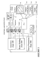
- the control system shown in Figure 3, comprises three control zones: autoclave zone 100, slurry holding zone 200, and slurry preparation zone 300.
- PLC 50 is used to manage the interlocks within and between the control zones, execute the sequential processing steps, monitor the status of hard-wired safety interlocks, enable manual control of system elements, and collect process data.
- the system uses a GE 30/90 PLC to execute the above-described functions.
- the system employs a graphical operator interface terminal (OIT) 55 to control and view the status of control elements and the setpoint and process variable for control loops within each process zone.
- OIT 55 is used to initiate and interrupt process operations for all three process zones.
- OIT 55 is used to initiate the vacuum pressure cycle for the slurry holding zone and the vacuum, pressure, and heating cycles in the autoclave zone.
- OIT 55 provides a graphical display of all hard-wired safety interlocks to examine the sensor(s) state associated with each interlock.
- OIT 55 also provides alarm information for error controls or out of control process loops.
- Individual, single loop process controllers 51, 52, 53, 54 are used to regulate process conditions between and in the autoclave and slurry holding zones.
- a video graphical recorder 56 is provided to record the actual process variables during the process cycle.
- the video graphical recorder 56 is provided with an Ethernet interface and PCMCIA memory card to facilitate transfer of process data from the recorder to a PC (not shown) or corporate network (not shown) for archiving or further analysis.
- Setpoint parameters for process conditions will be entered via OIT 55, transmitted to PLC 50, and relayed to individual process controllers 51-54.
- a communications interface is provided between PLC 50 and individual process controllers 51-54 capable of supporting transmission of process cycle parameters to process controllers 51-54 and process status and error conditions from process controllers 51-54 to PLC 50.
- the communications interface between PLC 50 and process controllers 51-54 is preferably Modbus.
- the Autoclave Zone 100 incorporates software programmed interlocks to manage the process transition between vacuum, positive pressure, heating, venting, and restoration of an OSHA safe oxygen level.
- the Autoclave Zone 100 also incorporates hard-wired safety interlocks to mitigate the impact of the following fault conditions: over pressure; application of electrical heating in the presence of an oxygen level capable of supporting combustion; over temperature condition for heated autoclave platen; attempt to open door in presence of autoclave pressure that is not near zero gauge pressure; attempt to open autoclave door in the absence of a safe oxygen level (>19.5% O 2 ); attempt to open valves between the slurry holding tank and the autoclave when the autoclave pressure is greater than atmospheric pressure; and attempt to open autoclave's high volume vent and blower valves when autoclave pressure is greater than atmospheric pressure.
- the autoclave 11 incorporates disperse control station 58, which is accessible by the operator when viewing autoclave 11 through sight glass 37.
- the operator has the ability from the control station to turn the autoclave illumination on/off, to equilibrate the vacuum pressure in autoclave 11 and slurry holding tank 10, confirm that both zones are at equal pressure, and control the release of slurry into autoclave 11 at high and low rates.
- the control station will provide a fault lamp to prompt the operator if a system fault condition exists.
- the autoclave zone further includes process controllers to regulate the ramp rate and dwell time for the vacuum cycle, pressure cycle, and heating cycle.
- the process cycle includes a software programmed interlock to prevent the restoration of normally oxygenated atmosphere until autoclave 11 is below a target temperature.
- This interlock helps prevent a potential combustion hazard due to the simultaneous presence of combustible fuel (uncatalyzed resin), oxygen, and ignition source (high temperature) being simultaneously present.
- the autoclave 11 incorporates automated control valves to control the flow into and out of the autoclave. These materials include slurry under vacuum, vacuum balance between autoclave and slurry holding tank, pressurization via nitrogen, vacuum, venting under various pressure condition, and normal atmosphere interchange.
- Control valves are provided so that the rate of change vacuum and the vacuum pressure can be digitally controlled via a process controller. Likewise, control valves and devices are provided so that the rate of change of pressure and the pressure can be digitally controlled via a process controller. Separate process controllers control vacuum and pressure.
- the system includes the ability to perform ramp and dwell cycles in the vacuum regime and pressurization cycles in the positive gauge pressure regime.
- Pressure switches are used to detect the transitions between the vacuum, ambient pressure, and above ambient pressure regimes for purposes of process sequencing and enforcement of safety interlocks.
- the autoclave supports up to four Type-K thermocouple temperature sensors.
- Three temperature sensors are dedicated for use in regulating the part process temperature. Two sensors are used in a cascade control scheme that measures both the tooling surface temperature and the temperature of the component. Another temperature sensor is used for an independent over temperature interlock. The remaining temperature sensor is available for general process monitoring.
- Pressure within the autoclave is monitored with a compound range pressure transducer capable of sensing from -14.7 psig to 150 psig.
- the pressure transducer supplies a BRAIN-enhanced, 4-20 mA signal.
- the pressure transducer incorporates a local pressure display.
- the autoclave pressure is visible via OIT 55.
- Oxygen sensor and associated alarm outputs are used to display the current oxygen content within the autoclave and oxygen status if the autoclave atmosphere is safe for human exposure or insufficient for combustion.
- the heating controls are sized sufficiently large to support a maximum heater wattage of 16 kW.
- the Slurry Holding Zone 200 incorporates a process controller to determine the vacuum ramp rate and regulation at vacuum pressure.
- No specific interlocks based on the slurry holding tank are provided to prevent or limit the transfer of slurry from the slurry preparation area to the slurry holding tank if the tank pressure is less than or equal to atmospheric pressure.
- a hard-wired interlock is provided to prevent the valve between the slurry holding tank and the slurry preparation area from opening if the slurry holding tank pressure is greater than atmospheric pressure.
- the slurry holding tank is outfitted with four limit switches to detect the fill level within the tank. These switches are the basis for a low-low, low, high and high-high level alarms. The normal maximum fill level is the high alarm. Status of the level switches is displayed on OIT 55.
- the slurry mixer 40 is activated from OIT 55.
- the mixer 40 is outfitted with a sensor to confirm that the mixer shaft is turning.
- the mixer is driven by a 3-phase AC induction motor with gearbox.
- Pressure within tank 10 is monitored with a compound range pressure transducer capable of sensing -14.7 psig to 150 psig.
- the pressure transducer supplies a BRAIN-enhanced, 4-20 mA signal.
- the pressure transducer incorporates a local pressure display.
- the slurry holding tank pressure is visible via OIT 55.
- Slurry Preparation Zone 300 incorporates transfer control station 59 to facilitate the transfer of resin from ball mill 20 to tank 10.
- the operator station incorporates a light indicating "Ready to Transfer.” This light implies that tank 10 is not full, that a slurry dispense is not in process (balance valve closed and slurry pinch valve closed), and that tank 10 is not at a pressure above ambient. Pushbuttons start and stop the transfer process.
- the pumping rate is controlled via the supplied air pressure.
- a manual regulator is provided to change this air pressure.
- a "transferring" light indicates that air is being supplied to diaphragm transfer pump 21 and slurry tank pinch valve 42 is open.
- a solenoid valve 33 is used to start and stop air flow to diaphragm pump 21.
- a pressure switch confirms operation of solenoid valve 33.
- An identical transfer control station 59' is provided at tank 10 to start/stop transfer when the operator is near quick disconnect valve 43 for flex hose 44 connecting the slurry preparation area to tank 10.
Landscapes
- Engineering & Computer Science (AREA)
- Mechanical Engineering (AREA)
- Chemical & Material Sciences (AREA)
- Composite Materials (AREA)
- Casting Or Compression Moulding Of Plastics Or The Like (AREA)
- Preparation Of Clay, And Manufacture Of Mixtures Containing Clay Or Cement (AREA)
- Paper (AREA)
Applications Claiming Priority (2)
| Application Number | Priority Date | Filing Date | Title |
|---|---|---|---|
| US10/648,355 US6830079B1 (en) | 2003-08-27 | 2003-08-27 | Integrated apparatus and method for filling porous composite preforms |
| US648355 | 2003-08-27 |
Publications (2)
| Publication Number | Publication Date |
|---|---|
| EP1510328A2 true EP1510328A2 (de) | 2005-03-02 |
| EP1510328A3 EP1510328A3 (de) | 2011-05-11 |
Family
ID=33490945
Family Applications (1)
| Application Number | Title | Priority Date | Filing Date |
|---|---|---|---|
| EP04255147A Withdrawn EP1510328A3 (de) | 2003-08-27 | 2004-08-26 | Integrierte Vorrichtung und Verfahren zur Füllung von porösen Vorformlingen aus Verbundwerkstoffen |
Country Status (4)
| Country | Link |
|---|---|
| US (1) | US6830079B1 (de) |
| EP (1) | EP1510328A3 (de) |
| JP (1) | JP2005096436A (de) |
| CN (1) | CN1623751A (de) |
Families Citing this family (21)
| Publication number | Priority date | Publication date | Assignee | Title |
|---|---|---|---|---|
| US7849729B2 (en) | 2006-12-22 | 2010-12-14 | The Boeing Company | Leak detection in vacuum bags |
| US8438909B2 (en) * | 2006-12-22 | 2013-05-14 | The Boeing Company | Device and method for detecting an air leak in a tool |
| US8568551B2 (en) | 2007-05-22 | 2013-10-29 | The Boeing Company | Pre-patterned layup kit and method of manufacture |
| US9770871B2 (en) | 2007-05-22 | 2017-09-26 | The Boeing Company | Method and apparatus for layup placement |
| US8936695B2 (en) | 2007-07-28 | 2015-01-20 | The Boeing Company | Method for forming and applying composite layups having complex geometries |
| US8707766B2 (en) | 2010-04-21 | 2014-04-29 | The Boeing Company | Leak detection in vacuum bags |
| US8333864B2 (en) | 2008-09-30 | 2012-12-18 | The Boeing Company | Compaction of prepreg plies on composite laminate structures |
| US7662048B2 (en) * | 2007-10-18 | 2010-02-16 | Libby Jason Armas | Golf swing training device |
| US8916010B2 (en) | 2007-12-07 | 2014-12-23 | The Boeing Company | Composite manufacturing method |
| US8752293B2 (en) | 2007-12-07 | 2014-06-17 | The Boeing Company | Method of fabricating structures using composite modules and structures made thereby |
| US10280063B2 (en) * | 2016-02-19 | 2019-05-07 | Alexander G. Innes | Pressurized transfer device |
| US10864640B1 (en) * | 2017-12-26 | 2020-12-15 | AGI Engineering, Inc. | Articulating arm programmable tank cleaning nozzle |
| US11413666B1 (en) | 2018-02-13 | 2022-08-16 | AGI Engineering, Inc. | Vertical travel robotic tank cleaning system |
| US11031149B1 (en) | 2018-02-13 | 2021-06-08 | AGI Engineering, Inc. | Nuclear abrasive slurry waste pump with backstop and macerator |
| US11577287B1 (en) | 2018-04-16 | 2023-02-14 | AGI Engineering, Inc. | Large riser extended reach sluicer and tool changer |
| US10786905B1 (en) | 2018-04-16 | 2020-09-29 | AGI Engineering, Inc. | Tank excavator |
| US11267024B2 (en) | 2018-06-11 | 2022-03-08 | AGI Engineering, Inc. | Programmable tank cleaning nozzle |
| EP3810333B1 (de) | 2018-06-11 | 2024-10-09 | Alex G. Innes | Programmierbares system zum reinigen von schienenfahrzeugtanks |
| CN109719972B (zh) * | 2019-01-26 | 2023-08-18 | 浙江理工大学 | 一种用于制备复合材料管件的树脂注入装置及控制方法 |
| US11571723B1 (en) | 2019-03-29 | 2023-02-07 | AGI Engineering, Inc. | Mechanical dry waste excavating end effector |
| CN112247098B (zh) * | 2020-09-21 | 2022-05-24 | 蚌埠隆华压铸机有限公司 | 一种压铸机防爆防夹手装置 |
Citations (1)
| Publication number | Priority date | Publication date | Assignee | Title |
|---|---|---|---|---|
| US4209482A (en) | 1977-08-05 | 1980-06-24 | Walter Schwarz | Method of producing shaped bodies of reinforced synthetic resin |
Family Cites Families (17)
| Publication number | Priority date | Publication date | Assignee | Title |
|---|---|---|---|---|
| GB286305A (en) * | 1927-03-03 | 1929-05-09 | Manuf De Machines Auxiliaires | Method and means for impregnating any articles with varnishes of synthetic resins |
| JPS608222B2 (ja) * | 1976-06-01 | 1985-03-01 | 旭硝子株式会社 | レジンインジエクシヨン成形方法 |
| US4609563A (en) * | 1985-02-28 | 1986-09-02 | Engelhard Corporation | Metered charge system for catalytic coating of a substrate |
| US5111871B1 (en) * | 1989-03-17 | 1993-12-28 | J. Cook Arnold | Method of vacuum casting |
| JPH0729304B2 (ja) * | 1992-02-26 | 1995-04-05 | 川崎重工業株式会社 | 複合材料の成形方法及び成形装置 |
| US5299619A (en) * | 1992-12-30 | 1994-04-05 | Hitchiner Manufacturing Co., Inc. | Method and apparatus for making intermetallic castings |
| US5340512A (en) * | 1993-01-29 | 1994-08-23 | Thomas & Betts Corporation | Polymer concrete electrical insulator and method and apparatus for making |
| US5489408A (en) * | 1993-03-08 | 1996-02-06 | Agency Of Industrial Science & Technology | Method for producing ceramics reinforced with three-dimensional fibers |
| JPH07169658A (ja) * | 1993-07-02 | 1995-07-04 | Electro Scient Ind Inc | 電子素子に成端ペーストを付けるための装置 |
| BR9510294A (pt) * | 1995-01-27 | 1997-11-11 | Sikorsky Aircraft Corp | Método para produzir artigos compósitos de núcleo alveolar |
| US6148899A (en) * | 1998-01-29 | 2000-11-21 | Metal Matrix Cast Composites, Inc. | Methods of high throughput pressure infiltration casting |
| US6099906A (en) * | 1998-06-22 | 2000-08-08 | Mcdonnell Douglas Corporation | Immersion process for impregnation of resin into preforms |
| JP2002060514A (ja) * | 2000-08-17 | 2002-02-26 | Mitsubishi Gas Chem Co Inc | プリプレグの製造方法 |
| JP2002086439A (ja) * | 2000-09-19 | 2002-03-26 | Matsushita Electric Works Ltd | 繊維補強セメント板の厚み制御方法 |
| JP4839523B2 (ja) * | 2001-04-17 | 2011-12-21 | 東レ株式会社 | 繊維強化樹脂の製造方法 |
| JP4590803B2 (ja) * | 2001-08-20 | 2010-12-01 | 東レ株式会社 | Rtm成形方法 |
| DE10239325B4 (de) * | 2002-08-27 | 2011-06-01 | Mt Aerospace Ag | Vorrichtung, Werkzeuganordnung und Verfahren zur Herstellung von Bauteilen aus Faserverbundwerkstoffen mittels temperatur- und druckgesteuerter Injektionstechnik |
-
2003
- 2003-08-27 US US10/648,355 patent/US6830079B1/en not_active Expired - Fee Related
-
2004
- 2004-08-26 EP EP04255147A patent/EP1510328A3/de not_active Withdrawn
- 2004-08-26 JP JP2004246126A patent/JP2005096436A/ja active Pending
- 2004-08-27 CN CN200410068258.1A patent/CN1623751A/zh active Pending
Patent Citations (1)
| Publication number | Priority date | Publication date | Assignee | Title |
|---|---|---|---|---|
| US4209482A (en) | 1977-08-05 | 1980-06-24 | Walter Schwarz | Method of producing shaped bodies of reinforced synthetic resin |
Also Published As
| Publication number | Publication date |
|---|---|
| US6830079B1 (en) | 2004-12-14 |
| CN1623751A (zh) | 2005-06-08 |
| JP2005096436A (ja) | 2005-04-14 |
| EP1510328A3 (de) | 2011-05-11 |
Similar Documents
| Publication | Publication Date | Title |
|---|---|---|
| US6830079B1 (en) | Integrated apparatus and method for filling porous composite preforms | |
| US5698163A (en) | Control system for processes using supercritical fluids | |
| US7104292B2 (en) | Auto-switching system for switch-over of gas storage and dispensing vessels in a multi-vessel array | |
| US5529212A (en) | Method of and apparatus for transporting and conditioning casting materials and for charging casting machines with them | |
| CA2369625C (en) | Apparatus and procedures for replenishing particulate materials | |
| US5643528A (en) | Controlled magnesium melt process, system and components therefor | |
| CN110976871B (zh) | 选择性激光烧结设备的粉末回收循环系统及其控制方法 | |
| SG182100A1 (en) | Mobile dosing, mixing and packaging plant | |
| CN103009482A (zh) | 全数字自动控制的火泥配料方法和装置 | |
| US5775542A (en) | Self contained drum dumping and hot melt holding tank and method of unloading, melting and dispensing a slug of hot melt material | |
| US20250297707A1 (en) | Hydrogen pressurizing rig | |
| CN207667584U (zh) | 一种适用于大型容器的混合气体可控配气系统 | |
| EP4361317A2 (de) | Vorrichtung und verfahren zur herstellung einer elektrolytlösung | |
| CA2178763C (en) | Ingot preheater and transfer for magnesium melt system | |
| CN207709002U (zh) | 一种适用于大型容器的混合气体快速配气系统 | |
| CN212398128U (zh) | 选择性激光烧结设备的粉末回收循环系统 | |
| JP3243572B2 (ja) | Pcb含有液の処理装置 | |
| CN111606295A (zh) | 沥青加注系统和沥青加注系统的控制方法 | |
| JP2004276963A (ja) | タンク型車両の荷役作業自動化システム | |
| JPH06315763A (ja) | 鋳造ライン故障管理方法 | |
| JPH0725478A (ja) | 材料物の自動移載装置及び材料物の自動移載方法 | |
| Kamalakannan et al. | Development of a computer based process control system for an autoclave to cure polymer matrix composites | |
| CN121446342A (zh) | 一种潜水混合气体自动快速配制系统及方法 | |
| CN117605959A (zh) | 一种液氯槽车充装过程的双重控制装置及充装方法 | |
| CN117101449A (zh) | 一种标准混合气的自动化配制装置和方法 |
Legal Events
| Date | Code | Title | Description |
|---|---|---|---|
| PUAI | Public reference made under article 153(3) epc to a published international application that has entered the european phase |
Free format text: ORIGINAL CODE: 0009012 |
|
| AK | Designated contracting states |
Kind code of ref document: A2 Designated state(s): AT BE BG CH CY CZ DE DK EE ES FI FR GB GR HU IE IT LI LU MC NL PL PT RO SE SI SK TR |
|
| AX | Request for extension of the european patent |
Extension state: AL HR LT LV MK |
|
| PUAL | Search report despatched |
Free format text: ORIGINAL CODE: 0009013 |
|
| AK | Designated contracting states |
Kind code of ref document: A3 Designated state(s): AT BE BG CH CY CZ DE DK EE ES FI FR GB GR HU IE IT LI LU MC NL PL PT RO SE SI SK TR |
|
| AX | Request for extension of the european patent |
Extension state: AL HR LT LV MK |
|
| 17P | Request for examination filed |
Effective date: 20111111 |
|
| AKX | Designation fees paid |
Designated state(s): FR GB IT |
|
| REG | Reference to a national code |
Ref country code: DE Ref legal event code: R108 |
|
| REG | Reference to a national code |
Ref country code: DE Ref legal event code: R108 Effective date: 20120118 |
|
| 17Q | First examination report despatched |
Effective date: 20120328 |
|
| STAA | Information on the status of an ep patent application or granted ep patent |
Free format text: STATUS: THE APPLICATION IS DEEMED TO BE WITHDRAWN |
|
| 18D | Application deemed to be withdrawn |
Effective date: 20130910 |