EP1510256A1 - Broyeur à agitateur avec un tuyau d'immersion pour l'aspiration et la séparation de matière à broyer et des corps broyants - Google Patents
Broyeur à agitateur avec un tuyau d'immersion pour l'aspiration et la séparation de matière à broyer et des corps broyants Download PDFInfo
- Publication number
- EP1510256A1 EP1510256A1 EP03019033A EP03019033A EP1510256A1 EP 1510256 A1 EP1510256 A1 EP 1510256A1 EP 03019033 A EP03019033 A EP 03019033A EP 03019033 A EP03019033 A EP 03019033A EP 1510256 A1 EP1510256 A1 EP 1510256A1
- Authority
- EP
- European Patent Office
- Prior art keywords
- grinding
- mill according
- dip tube
- agitator mill
- agitator
- Prior art date
- Legal status (The legal status is an assumption and is not a legal conclusion. Google has not performed a legal analysis and makes no representation as to the accuracy of the status listed.)
- Withdrawn
Links
Images


Classifications
-
- B—PERFORMING OPERATIONS; TRANSPORTING
- B02—CRUSHING, PULVERISING, OR DISINTEGRATING; PREPARATORY TREATMENT OF GRAIN FOR MILLING
- B02C—CRUSHING, PULVERISING, OR DISINTEGRATING IN GENERAL; MILLING GRAIN
- B02C17/00—Disintegrating by tumbling mills, i.e. mills having a container charged with the material to be disintegrated with or without special disintegrating members such as pebbles or balls
- B02C17/16—Mills in which a fixed container houses stirring means tumbling the charge
- B02C17/161—Arrangements for separating milling media and ground material
-
- B—PERFORMING OPERATIONS; TRANSPORTING
- B02—CRUSHING, PULVERISING, OR DISINTEGRATING; PREPARATORY TREATMENT OF GRAIN FOR MILLING
- B02C—CRUSHING, PULVERISING, OR DISINTEGRATING IN GENERAL; MILLING GRAIN
- B02C17/00—Disintegrating by tumbling mills, i.e. mills having a container charged with the material to be disintegrated with or without special disintegrating members such as pebbles or balls
- B02C17/18—Details
- B02C17/183—Feeding or discharging devices
Definitions
- the invention relates to a stirred mill according to the preamble of claim 1.
- Agitator mill of the generic type has a rotationally driven Grind container on, between which and serving as a lid, non-rotatably arranged on the machine stand cover a seal is provided, which serves as a splash guard. With overpressure these can Agitator mills are not operated. The regrind removal works without pressure, d. H. against atmospheric pressure.
- the invention is based on the object, an agitator mill of the generic type Art to design so that the separation of Mahlos stresses with little design effort and in a very robust design is possible.
- the essence of the invention is that the grinding stock Mahlosterrorism mixture after the grinding process from the Agitator mill is sucked through a dip tube and the separation the Mahlangesterrorism carried by weight and inertial forces.
- Mahlosterrorism move due to gravity and due to the Entrainment through the moving under the dip tube Mahlosève bed directly back into the grinding room.
- the realization is very easy and inexpensive.
- the components to be used can be very simple and be protected against wear with little effort. It also small Mahlösêt can be separated.
- the invention can be used particularly advantageously if according to claim 2 and the grinding container is rotatably driven, so that a Mahlos crusherströmung is forced in the grinding room.
- the eccentric arrangement of Immersion tube according to claim 3 causes that in the dip tube down falling Mahlos stresses of the rotating Mahlosève bed be taken along, because the dip tube in the area in the grinding room opens, where the Mahlos stresses bed performs a movement.
- the eccentric arrangement of the at least one agitator according to claim 4 supports this.
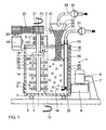
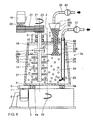
- the agitator mill shown in FIGS. 1 and 2 has a substantially cylindrical grinding container 1, whose central longitudinal axis of the second vertical, d. H. the grinding container 1 is vertical. He is down through closed a transverse to the axis 2 extending bottom 3. He supports himself via a concentric with the axis 2 arranged pivot bearing 4 opposite an only indicated machine stand 5 from, d. H. the grinding container 1 is rotatable about its central longitudinal axis 2.
- a rotary drive for the grinding container 1 is a grinding container drive motor supported relative to the machine stand 5 6 provided, the shaft 7 parallel to the axis of the second runs and a pinion 8 and at the lower outer circumference attached to the grinding container 1 sprocket 9 the grinding container 1 in Direction of rotation 10 drives. Due to a corresponding reduction ratio the pinion 8 relative to the ring gear 9, the drive of the grinding container 1 at a relatively low speed. Instead of a pinion 8 can of course also used a friction wheel drive become.
- an agitator 11 is arranged, which is substantially and in the usual way from a stirrer shaft 12 and at this arranged and radially projecting from her stirring tools 13 consists.
- the stirring tools 13 in the present case are stirring disks with passages 14.
- the agitator shaft 12 is in her the bottom 3 opposite upper portion in a stirring shaft bearing 15 lying horizontally. This bearing 15 is connected to a non-rotatable in unsupported manner supported against the machine stand 5, frontal cover 16 is held. Between the cover 16 and the upper edge 17 of the grinding container 1 is a seal 18, that is arranged concentrically to the central longitudinal axis 2 of the grinding container 1 is.
- the seal 18 is not with the edge 17 of the grinding container 1 connected, since the latter is rotatable and serving as a cover cover 16 stationary, albeit removable arranged on the machine stand 5 is.
- the cover 16 with the seal 18 serve as splash guard; the grinding container 1 is not sealed pressure-resistant, d. H. in the grinding container 1 prevails about atmospheric pressure.
- the agitator 11 is connected by means of a with the machine stand 5 Agitator drive motor 19 driven, the shaft 20 parallel to the agitator axis 21, but with respect to the latter to an eccentricity e1 is offset.
- the drive is by means of a belt drive 22nd transferred to the agitator shaft 12.
- the drive motor 19 drives the Agitator 11 in the direction of rotation 23, which is rectified with the direction of rotation 10 can be; but the directions of rotation 10 and 23 can also be against each other be directed.
- a regrind supply line 24 passed and held, the outlet opening 25 in the vicinity the bottom 3 of the grinding container 1 is located.
- This line 24 is shown in the Embodiment designed as a flow deflector 26.
- This deflector 26 may have a deflection surface 27, resulting in the result has an impinging regrind grinding aid flow radially to is diverted inside.
- the conduit 24 is near the grinding chamber wall 28 arranged.
- the conduit 24 only as a pipe be educated. Their essential function is the grinding material feed.
- the Regrind feed line 24 becomes regrind by means of a regrind feed pump 31 fed through the outlet opening 25 in the lower area of the grinding container 1, that is in the vicinity of the bottom 3, in this occurs.
- the device 32 Located at the top outside of the grinding chamber 34 End, the device 32 has a funnel-shaped upward widening Section 38, which is completely closed. From him flows to the top of a suction line 39, in which a regrind suction pump 40 is located. At the extended portion 38 is still a vibration exciter 41, which cause the device 32 to vibrate can.
- the working method is as follows:
- the grinding material supply line 24 is by means of the grinding stock feed pump 31 millbase in a pumpable state, usually as a suspension, fed. So there is a so-called wet grinding instead.
- Mahlraum 34 is a bed of Mahlosangen 37 in the form of a Partial filling of the grinding chamber 34 with Mahlos stressesn 37, the upward is limited by the mirror 36.
- the agitator 11 is in the direction of rotation 23 driven; the grinding container 1 is driven in the direction of rotation 10. The speeds are chosen so that the bed of Mahlos crushern 37 is obtained as a compact bed; the Mahltos crusher so not fluidized in the millbase.
- auxiliary grinding bodies 37 flow upwards with the millbase, while unused and heavy auxiliary grinding bodies 37 remain in the grinding chamber 34.
- Mahltos emotions 37 there is a constant rise and sedimentation of Mahltos stresses 37 in the gravitational field.
- a separation mirror 42 between Mahlos stressesn 37 and Mahlos stressesn free regrind equilibrium state Mahltosève filling in dip tube 33 results from their own weight.
- Mahltos emotions those of steel, Al 2 O 3 or ZrO 2 or other suitable materials can be used.
- the diameter of the unconsumed, that is not worn new Mahlosêt 37 is in the range of 1 to 10 mm, preferably from 4 to 7 mm.
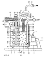
- the second embodiment of Fig. 3 differs from that 1 and 2 only by the configuration of the Mahlgut Mahlos emotions suction and separator 32 '.
- To the extended section 38 is still followed by a suction and separation housing 43, from which the Suction line 39 opens.
- this extraction and separation housing 43 are parallel to each other and oblique to the vertical arranged fins 44, which formed similar to a lamella separator are.
- On them are also very small Mahlos stresses 37 through Sedimentation is deposited and wandered back into the facility 32 'located filling from Mahlos emotionsn 37, where they then already be subjected to the described return process.
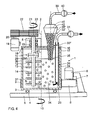
- the third embodiment of Fig. 4 differs from the aforementioned again by the design of the grinding stock grinding auxiliary body suction and separator 32 ".
- this embodiment is the dip tube 33 "down, so the grinding chamber 34 out, tapered, so not cylindrical, trained.
- the upper extended section 38 " has above the separation mirror 42 in addition Protection sieve 45, by means of which even very small Mahltosharm 37 be held back.
- Protection sieve 45 can of course also be used in the embodiment of FIGS. 1 and 2.
- the fourth embodiment of FIG. 5 differs again of the above only by the configuration of the grinding stock grinding auxiliary body suction and separator 32 "'.
- the dip tube 33 '' ' is substantially cylindrical and has in its upper outer area has only a tapered transition section 46, since the diameter D of the dip tube 33 '' 'naturally is significantly larger than the diameter d of the suction line 39th Der Diameter D of the dip tube 33 '' 'is at least in the region of the inlet opening 35 '' 'at least ten times the diameter of the largest Mahltos emotions 37.
- the dip tube 33' ''' At its lower the inlet opening 35 '' ' the dip tube 33 '' 'associated end, the dip tube 33' '' a Recess 47, located in the flow path of Mahltos emotions flow 29, which is shown only in Fig. 2. There is also the recess 47 shown in its flow 29 correct location. The recess 47 is located - with respect to the direction of the flow 29 - on the downstream side of the dip tube 33 '' ', so that located in the lower region of the dip tube 33 '' 'or there sinking Mahlos 1969 37 particularly easy from passing by Bed from Mahltos emotionsn 37 are taken.
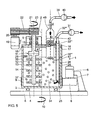
- the fifth embodiment of FIG. 6 corresponds to that of FIG. 5, wherein only the dip tube 33 '' 'opposite to the direction of flow 29 of the millbase and the Mahlcous stresses 37 is inclined. Also located here the recess 47 in the flow shadow of the device 32 '' '.
- This embodiment is particularly advantageous. As it turned out has, in this case increase the Mahlcous stresses 37 only to a small extent in the dip tube 33 'upwards. They store rather preferred in the lower, the inlet opening 35 'adjacent region, on the - with respect to the flow 29 - upstream side of the dip tube 33 '' '.
- the sixth embodiment of FIG. 7 corresponds in terms of Design of the Mahlgut Mahlos stresses suction and separation device 32 to that of FIGS. 1 and 2, although indicated, that the dip tube 33 be adjustable in height in a sliding guide 49 can.
- the grinding container 1a is not cylindrical, but expands upwards.
- the grinding container drive motor 6 arranged opposite to the previous embodiments.
- the pinion 8 acts on a sprocket 9a, which is on the mill container side Part of the pivot bearing 4a is attached.
- the seventh embodiment of Fig. 8 is different from that according to Fig. 7, characterized in that the grinding container 1 b tapers conically upwards. Further, the expanded portion 38b of the dip tube 33b asymmetrically formed. Also in this embodiment, the deflector 26 not on the grinding chamber wall 28b.
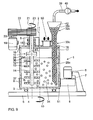
- the eighth embodiment of FIG. 9 again relates to a stirred mill in the basic embodiment described above according to FIGS. 1 to 6.
- the grinding material feed takes place through one in the cover 16 grind inlet 50.
- this can be the supply of dry millbase and liquid separated by the millbase inlet 50 done.
- the deflector 26c is hereby used as regrind grinding aid suction and separator 32c.
- an inlet opening 51 is formed at the bottom, adjacent to the bottom 3 of the grinding container 1 located end.
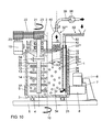
- the ninth embodiment of Fig. 10 is different from that fourth embodiment of FIG. 5, characterized in that the agitator mill is designed for a dry grinding.
- a regrind feeding device 52 provided in the form of a feed screw machine 53, by means of which the pulverulent millbase in the mill feed line 24th is encouraged.
- a gap 54th provided by the outside air according to the flow direction arrow 55 can flow into the grinding chamber 34.
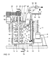
- the tenth embodiment of FIG. 11 substantially corresponds to that of Fig. 10, wherein only the dip tube 33 '' '' according to the Representation in Fig. 6 against the direction of the flow 29 of the ground material and the grinding aid body 37 is inclined. Also here is the Recess 47 '' '' in the flow shadow of the device 32 "". Also here, in accordance with the embodiment of FIG. 10th the recess 47 '' ''' designed so that they on the one hand in the bed Mahlös stresses 37 and ground material dips, but also to above the Surface 57 protrudes, so that according to the flow direction arrow 55 incoming air can be sucked through.
- the cross-section of the device 32 does not have to be circular be; it can also be designed as a polygon or asymmetrical.
Priority Applications (12)
| Application Number | Priority Date | Filing Date | Title |
|---|---|---|---|
| EP03019033A EP1510256A1 (fr) | 2003-08-22 | 2003-08-22 | Broyeur à agitateur avec un tuyau d'immersion pour l'aspiration et la séparation de matière à broyer et des corps broyants |
| RU2004122031/03A RU2343979C2 (ru) | 2003-08-22 | 2004-07-20 | Шаровая мельница-мешалка |
| ES04017804T ES2304248T3 (es) | 2003-08-22 | 2004-07-28 | Molino agitador con tubo de inmersion para la aspiracion y separacion de material molido y cuerpos auxiliares de molienda. |
| AT04017804T ATE392259T1 (de) | 2003-08-22 | 2004-07-28 | Rührwerksmühle mit tauchrohr zur absaugung und trennung von mahlgut und mahlhilfskörpern |
| PL04017804T PL1508376T3 (pl) | 2003-08-22 | 2004-07-28 | Młyn z mieszadłem i rurą nurnikową do odsysania i rozdzielania materiału mielonego i pomocniczych elementów rozdrabniających |
| EP04017804A EP1508376B1 (fr) | 2003-08-22 | 2004-07-28 | Broyeur agitateur avec un tuyau d'immersion pour l'aspiration et la séparation de matière à broyer et des corps broyants |
| DE502004006822T DE502004006822D1 (de) | 2003-08-22 | 2004-07-28 | Rührwerksmühle mit Tauchrohr zur Absaugung und Trennung von Mahlgut und Mahlhilfskörpern |
| AU2004203593A AU2004203593B2 (en) | 2003-08-22 | 2004-08-04 | Agitator mill |
| ZA2004/06269A ZA200406269B (en) | 2003-08-22 | 2004-08-05 | Agitator mill |
| US10/918,369 US7264191B2 (en) | 2003-08-22 | 2004-08-16 | Agitator mill |
| CNB2004100570016A CN100518943C (zh) | 2003-08-22 | 2004-08-20 | 搅拌磨机 |
| JP2004240745A JP4557634B2 (ja) | 2003-08-22 | 2004-08-20 | 撹拌式ミル |
Applications Claiming Priority (1)
| Application Number | Priority Date | Filing Date | Title |
|---|---|---|---|
| EP03019033A EP1510256A1 (fr) | 2003-08-22 | 2003-08-22 | Broyeur à agitateur avec un tuyau d'immersion pour l'aspiration et la séparation de matière à broyer et des corps broyants |
Publications (1)
| Publication Number | Publication Date |
|---|---|
| EP1510256A1 true EP1510256A1 (fr) | 2005-03-02 |
Family
ID=34089593
Family Applications (1)
| Application Number | Title | Priority Date | Filing Date |
|---|---|---|---|
| EP03019033A Withdrawn EP1510256A1 (fr) | 2003-08-22 | 2003-08-22 | Broyeur à agitateur avec un tuyau d'immersion pour l'aspiration et la séparation de matière à broyer et des corps broyants |
Country Status (9)
| Country | Link |
|---|---|
| US (1) | US7264191B2 (fr) |
| EP (1) | EP1510256A1 (fr) |
| JP (1) | JP4557634B2 (fr) |
| CN (1) | CN100518943C (fr) |
| AT (1) | ATE392259T1 (fr) |
| AU (1) | AU2004203593B2 (fr) |
| DE (1) | DE502004006822D1 (fr) |
| RU (1) | RU2343979C2 (fr) |
| ZA (1) | ZA200406269B (fr) |
Cited By (1)
| Publication number | Priority date | Publication date | Assignee | Title |
|---|---|---|---|---|
| JP2005066597A (ja) * | 2003-08-22 | 2005-03-17 | Maschinenfabrik Gustav Eirich Gmbh & Co Kg | 撹拌式ミル |
Families Citing this family (10)
| Publication number | Priority date | Publication date | Assignee | Title |
|---|---|---|---|---|
| US7188806B2 (en) * | 2004-10-22 | 2007-03-13 | B E Aerospace, Inc. | Aircraft passenger accommodation unit with deployable bed |
| NZ545960A (en) | 2006-03-15 | 2008-04-30 | Environmental Decontamination | Milling apparatus |
| KR100773493B1 (ko) | 2006-06-05 | 2007-11-05 | 유니원기연(주) | 원심분쇄밀 |
| WO2010003990A1 (fr) * | 2008-07-10 | 2010-01-14 | Frewitt Fabrique De Machines S.A. | Broyeur de perles à séparateur |
| DE102010052656A1 (de) * | 2010-11-26 | 2012-05-31 | Netzsch-Feinmahltechnik Gmbh | Hydraulische Mahlkugel Zu- und Abfuhr für Rührwerkskugelmühlen |
| PT2999543T (pt) | 2013-05-21 | 2023-04-11 | Smidth As F L | Métodos e aparelhos para a monitorização contínua de desgaste em circuitos de trituração |
| US20190168233A1 (en) * | 2017-12-01 | 2019-06-06 | Metso Minerals Industries, Inc. | Vertical grinding mill, grinding media handling system, grinding media discharge device, and method for handling grinding media |
| KR102007389B1 (ko) * | 2018-04-30 | 2019-08-05 | 주식회사 태환자동화산업 | 카카오 콘칭장치 |
| EP3799960A1 (fr) * | 2019-10-01 | 2021-04-07 | Bühler AG | Broyeur à agitateur |
| CN112535989A (zh) * | 2020-11-22 | 2021-03-23 | 苏州比达尔创新材料科技有限公司 | 一种纺织面料染色用沉淀颗粒高效研磨装置 |
Citations (2)
| Publication number | Priority date | Publication date | Assignee | Title |
|---|---|---|---|---|
| EP0369149A1 (fr) * | 1988-11-18 | 1990-05-23 | Eirich, Walter | Broyeur malaxeur à boulets |
| EP1323476A1 (fr) * | 2001-12-24 | 2003-07-02 | Maschinenfabrik Gustav Eirich GmbH & Co KG | Broyeur agitateur avec une pompe d'alimentation et une pompe d'extraction |
Family Cites Families (7)
| Publication number | Priority date | Publication date | Assignee | Title |
|---|---|---|---|---|
| US2651582A (en) * | 1952-12-22 | 1953-09-08 | Cellulose Fibers Inc | Method of making a cuprammonium cellulose solution |
| DE3520409A1 (de) * | 1985-06-07 | 1986-12-11 | Hubert Eirich | Druckfester mischer |
| SE469417B (sv) * | 1991-12-20 | 1993-07-05 | Sala International Ab | Saett och anordning foer finmalning av foer filleraendamaal anvaendbara mineral i torrt tillstaand |
| JPH0673637B2 (ja) * | 1991-12-25 | 1994-09-21 | 大平洋機工株式会社 | 連続式の揺動式分散・粉砕装置 |
| DE10253791A1 (de) * | 2001-12-24 | 2003-07-03 | Gustav Eirich Gmbh & Co Kg | Rührwerksmühle |
| EP1510256A1 (fr) * | 2003-08-22 | 2005-03-02 | Maschinenfabrik Gustav Erich GmbH & Co. KG | Broyeur à agitateur avec un tuyau d'immersion pour l'aspiration et la séparation de matière à broyer et des corps broyants |
| ES2304248T3 (es) * | 2003-08-22 | 2008-10-01 | MASCHINENFABRIK GUSTAV EIRICH GMBH & CO KG | Molino agitador con tubo de inmersion para la aspiracion y separacion de material molido y cuerpos auxiliares de molienda. |
-
2003
- 2003-08-22 EP EP03019033A patent/EP1510256A1/fr not_active Withdrawn
-
2004
- 2004-07-20 RU RU2004122031/03A patent/RU2343979C2/ru not_active IP Right Cessation
- 2004-07-28 DE DE502004006822T patent/DE502004006822D1/de active Active
- 2004-07-28 AT AT04017804T patent/ATE392259T1/de active
- 2004-08-04 AU AU2004203593A patent/AU2004203593B2/en not_active Ceased
- 2004-08-05 ZA ZA2004/06269A patent/ZA200406269B/en unknown
- 2004-08-16 US US10/918,369 patent/US7264191B2/en not_active Expired - Fee Related
- 2004-08-20 CN CNB2004100570016A patent/CN100518943C/zh not_active Expired - Fee Related
- 2004-08-20 JP JP2004240745A patent/JP4557634B2/ja not_active Expired - Fee Related
Patent Citations (2)
| Publication number | Priority date | Publication date | Assignee | Title |
|---|---|---|---|---|
| EP0369149A1 (fr) * | 1988-11-18 | 1990-05-23 | Eirich, Walter | Broyeur malaxeur à boulets |
| EP1323476A1 (fr) * | 2001-12-24 | 2003-07-02 | Maschinenfabrik Gustav Eirich GmbH & Co KG | Broyeur agitateur avec une pompe d'alimentation et une pompe d'extraction |
Cited By (2)
| Publication number | Priority date | Publication date | Assignee | Title |
|---|---|---|---|---|
| JP2005066597A (ja) * | 2003-08-22 | 2005-03-17 | Maschinenfabrik Gustav Eirich Gmbh & Co Kg | 撹拌式ミル |
| JP4557634B2 (ja) * | 2003-08-22 | 2010-10-06 | マシーネンファブリーク・グスタフ・アイリッヒ・ゲゼルシャフト・ミット・ベシュレンクテル・ハフツング・ウント・コムパニー・コマンディットゲゼルシャフト | 撹拌式ミル |
Also Published As
| Publication number | Publication date |
|---|---|
| CN1583276A (zh) | 2005-02-23 |
| US20050040266A1 (en) | 2005-02-24 |
| RU2343979C2 (ru) | 2009-01-20 |
| AU2004203593A1 (en) | 2005-03-10 |
| RU2004122031A (ru) | 2006-01-20 |
| ATE392259T1 (de) | 2008-05-15 |
| JP2005066597A (ja) | 2005-03-17 |
| JP4557634B2 (ja) | 2010-10-06 |
| US7264191B2 (en) | 2007-09-04 |
| DE502004006822D1 (de) | 2008-05-29 |
| CN100518943C (zh) | 2009-07-29 |
| AU2004203593B2 (en) | 2009-02-19 |
| ZA200406269B (en) | 2005-08-31 |
Similar Documents
| Publication | Publication Date | Title |
|---|---|---|
| EP0369149B1 (fr) | Broyeur malaxeur à boulets | |
| EP0700723B1 (fr) | Broyeur agitateur | |
| DE4432200C1 (de) | Rührwerksmühle | |
| EP0370022B1 (fr) | Melangeur-broyeur | |
| DE894647C (de) | Drehbarer Sichter | |
| DE3633747A1 (de) | Vertikale rollenmuehle | |
| EP1510256A1 (fr) | Broyeur à agitateur avec un tuyau d'immersion pour l'aspiration et la séparation de matière à broyer et des corps broyants | |
| EP0700721B1 (fr) | Broyeur agitateur | |
| DE3038794C2 (de) | Rührwerksmühle | |
| DE19632757A1 (de) | Rührwerksmühle | |
| EP3573762B1 (fr) | Broyeur agitateur | |
| DE10253791A1 (de) | Rührwerksmühle | |
| EP0700724B2 (fr) | Procédé et appareil pour le broyage continu autogène d'une matière à traiter fluide | |
| EP1027161B1 (fr) | Procede et dispositif pour le broyage a l'etat mouille de solides dans des liquides | |
| EP0163112B1 (fr) | Procédé et dispositif pour la séparation centrifuge de mélanges de minéraux à grains fins | |
| DE2032014C3 (de) | Diffusionsturm | |
| EP1508376B1 (fr) | Broyeur agitateur avec un tuyau d'immersion pour l'aspiration et la séparation de matière à broyer et des corps broyants | |
| DE3318312C2 (fr) | ||
| CH621268A5 (fr) | ||
| DE10338592A1 (de) | Rührwerksmühle | |
| DE1757953C3 (de) | Rührwerksmühle | |
| DE540733C (de) | Staubmuehle, bei der Mahlkugeln zwischen einem umlaufenden und einem feststehenden Mahlteller abrollen | |
| DE1185467B (de) | Vorrichtung zum Aufloesen von Faserstoffen zur Herstellung von Papier | |
| EP1323476A1 (fr) | Broyeur agitateur avec une pompe d'alimentation et une pompe d'extraction | |
| DE3927076A1 (de) | Ruehrwerksmuehle |
Legal Events
| Date | Code | Title | Description |
|---|---|---|---|
| PUAI | Public reference made under article 153(3) epc to a published international application that has entered the european phase |
Free format text: ORIGINAL CODE: 0009012 |
|
| AK | Designated contracting states |
Kind code of ref document: A1 Designated state(s): AT BE BG CH CY CZ DE DK EE ES FI FR GB GR HU IE IT LI LU MC NL PT RO SE SI SK TR |
|
| AX | Request for extension of the european patent |
Extension state: AL LT LV MK |
|
| AKX | Designation fees paid | ||
| REG | Reference to a national code |
Ref country code: DE Ref legal event code: 8566 |
|
| STAA | Information on the status of an ep patent application or granted ep patent |
Free format text: STATUS: THE APPLICATION IS DEEMED TO BE WITHDRAWN |
|
| 18D | Application deemed to be withdrawn |
Effective date: 20050903 |