EP1510178B1 - Ultraschallgerät und Ultraschall-Behandlungssystem - Google Patents
Ultraschallgerät und Ultraschall-Behandlungssystem Download PDFInfo
- Publication number
- EP1510178B1 EP1510178B1 EP04020181A EP04020181A EP1510178B1 EP 1510178 B1 EP1510178 B1 EP 1510178B1 EP 04020181 A EP04020181 A EP 04020181A EP 04020181 A EP04020181 A EP 04020181A EP 1510178 B1 EP1510178 B1 EP 1510178B1
- Authority
- EP
- European Patent Office
- Prior art keywords
- ultrasonic transducer
- end part
- ultrasonic
- horn
- unit
- Prior art date
- Legal status (The legal status is an assumption and is not a legal conclusion. Google has not performed a legal analysis and makes no representation as to the accuracy of the status listed.)
- Expired - Lifetime
Links
- 238000009210 therapy by ultrasound Methods 0.000 title claims description 61
- 238000011282 treatment Methods 0.000 claims description 46
- 238000003780 insertion Methods 0.000 claims description 10
- 230000037431 insertion Effects 0.000 claims description 10
- 230000004048 modification Effects 0.000 description 22
- 238000012986 modification Methods 0.000 description 22
- 238000005452 bending Methods 0.000 description 20
- 239000010410 layer Substances 0.000 description 10
- 239000004020 conductor Substances 0.000 description 9
- 206010028980 Neoplasm Diseases 0.000 description 8
- 238000005286 illumination Methods 0.000 description 7
- 230000000740 bleeding effect Effects 0.000 description 5
- 210000004204 blood vessel Anatomy 0.000 description 4
- 210000000078 claw Anatomy 0.000 description 4
- 238000003384 imaging method Methods 0.000 description 3
- 238000000034 method Methods 0.000 description 3
- 238000003466 welding Methods 0.000 description 3
- 230000002093 peripheral effect Effects 0.000 description 2
- 239000011241 protective layer Substances 0.000 description 2
- 230000003014 reinforcing effect Effects 0.000 description 2
- 239000000523 sample Substances 0.000 description 2
- 238000005245 sintering Methods 0.000 description 2
- 208000037062 Polyps Diseases 0.000 description 1
- 239000002184 metal Substances 0.000 description 1
- 238000002360 preparation method Methods 0.000 description 1
- 238000002604 ultrasonography Methods 0.000 description 1
Images


Classifications
-
- A—HUMAN NECESSITIES
- A61—MEDICAL OR VETERINARY SCIENCE; HYGIENE
- A61B—DIAGNOSIS; SURGERY; IDENTIFICATION
- A61B17/00—Surgical instruments, devices or methods
- A61B17/22—Implements for squeezing-off ulcers or the like on inner organs of the body; Implements for scraping-out cavities of body organs, e.g. bones; for invasive removal or destruction of calculus using mechanical vibrations; for removing obstructions in blood vessels, not otherwise provided for
- A61B17/22004—Implements for squeezing-off ulcers or the like on inner organs of the body; Implements for scraping-out cavities of body organs, e.g. bones; for invasive removal or destruction of calculus using mechanical vibrations; for removing obstructions in blood vessels, not otherwise provided for using mechanical vibrations, e.g. ultrasonic shock waves
- A61B17/22012—Implements for squeezing-off ulcers or the like on inner organs of the body; Implements for scraping-out cavities of body organs, e.g. bones; for invasive removal or destruction of calculus using mechanical vibrations; for removing obstructions in blood vessels, not otherwise provided for using mechanical vibrations, e.g. ultrasonic shock waves in direct contact with, or very close to, the obstruction or concrement
- A61B17/2202—Implements for squeezing-off ulcers or the like on inner organs of the body; Implements for scraping-out cavities of body organs, e.g. bones; for invasive removal or destruction of calculus using mechanical vibrations; for removing obstructions in blood vessels, not otherwise provided for using mechanical vibrations, e.g. ultrasonic shock waves in direct contact with, or very close to, the obstruction or concrement the ultrasound transducer being inside patient's body at the distal end of the catheter
-
- A—HUMAN NECESSITIES
- A61—MEDICAL OR VETERINARY SCIENCE; HYGIENE
- A61B—DIAGNOSIS; SURGERY; IDENTIFICATION
- A61B17/00—Surgical instruments, devices or methods
- A61B17/32—Surgical cutting instruments
- A61B17/320016—Endoscopic cutting instruments, e.g. arthroscopes, resectoscopes
-
- A—HUMAN NECESSITIES
- A61—MEDICAL OR VETERINARY SCIENCE; HYGIENE
- A61B—DIAGNOSIS; SURGERY; IDENTIFICATION
- A61B17/00—Surgical instruments, devices or methods
- A61B17/22—Implements for squeezing-off ulcers or the like on inner organs of the body; Implements for scraping-out cavities of body organs, e.g. bones; for invasive removal or destruction of calculus using mechanical vibrations; for removing obstructions in blood vessels, not otherwise provided for
- A61B17/22004—Implements for squeezing-off ulcers or the like on inner organs of the body; Implements for scraping-out cavities of body organs, e.g. bones; for invasive removal or destruction of calculus using mechanical vibrations; for removing obstructions in blood vessels, not otherwise provided for using mechanical vibrations, e.g. ultrasonic shock waves
- A61B2017/22027—Features of transducers
-
- A—HUMAN NECESSITIES
- A61—MEDICAL OR VETERINARY SCIENCE; HYGIENE
- A61B—DIAGNOSIS; SURGERY; IDENTIFICATION
- A61B17/00—Surgical instruments, devices or methods
- A61B17/32—Surgical cutting instruments
- A61B17/320068—Surgical cutting instruments using mechanical vibrations, e.g. ultrasonic
- A61B2017/320089—Surgical cutting instruments using mechanical vibrations, e.g. ultrasonic node location
-
- A—HUMAN NECESSITIES
- A61—MEDICAL OR VETERINARY SCIENCE; HYGIENE
- A61B—DIAGNOSIS; SURGERY; IDENTIFICATION
- A61B17/00—Surgical instruments, devices or methods
- A61B17/32—Surgical cutting instruments
- A61B17/320068—Surgical cutting instruments using mechanical vibrations, e.g. ultrasonic
- A61B17/320092—Surgical cutting instruments using mechanical vibrations, e.g. ultrasonic with additional movable means for clamping or cutting tissue, e.g. with a pivoting jaw
- A61B2017/320094—Surgical cutting instruments using mechanical vibrations, e.g. ultrasonic with additional movable means for clamping or cutting tissue, e.g. with a pivoting jaw additional movable means performing clamping operation
-
- A—HUMAN NECESSITIES
- A61—MEDICAL OR VETERINARY SCIENCE; HYGIENE
- A61B—DIAGNOSIS; SURGERY; IDENTIFICATION
- A61B90/00—Instruments, implements or accessories specially adapted for surgery or diagnosis and not covered by any of the groups A61B1/00 - A61B50/00, e.g. for luxation treatment or for protecting wound edges
- A61B90/36—Image-producing devices or illumination devices not otherwise provided for
- A61B90/37—Surgical systems with images on a monitor during operation
- A61B2090/373—Surgical systems with images on a monitor during operation using light, e.g. by using optical scanners
Definitions
- the present invention relates to an ultrasonic treatment device for use in combination with endoscopes, and to an ultrasonic treatment system.
- U.S. Patent 6,231,578 discloses an ultrasonic treatment device to be inserted into the channel of an endoscope and thereby to be inserted into a patient.
- This apparatus is guided into the view field of the endoscope and used to treat the living tissues in the patient.
- the apparatus has a flexible wire, a tubular sheath and an operation unit.
- the flexible wire has a loop on its distal end.
- the flexible wire extends through the tubular sheath and can slide in the sheath.
- the operation unit is coupled to the proximal end of the tubular sheath.
- the operation unit has an actuator and an ultrasonic transducer.
- the actuator can move the flexible wire in the axial direction of the tubular sheath.
- the ultrasonic transducer can generate ultrasonic vibration.
- the ultrasonic vibration generated by the transducer is transmitted to the flexible wire.
- the actuator moves the flexible wire along the axis of the tubular sheath. If the wire is pulled toward the proximal end of the sheath, the loop will go into the sheath and will close. If the wire is pushed toward the distal end of the sheath, the loop will protrude from the sheath and will open. Assume that the loop is wrapped around a tumor such as polyp while it is opening. Also, assume that the wire is pulled toward the proximal end of the sheath. Then, the loop closes and holds the tumor. In this condition, ultrasonic vibration may be transmitted from the ultrasonic transducer to the flexible wire, thereby cutting the tumor.
- Jpn. Pat. Appln. KOKAI Publication No. 11-56867 discloses an ultrasonic treatment device.
- This apparatus is different in structure from the apparatus disclosed in the above-identified U.S. patent.
- the apparatus has a support rod, an ultrasonic transducer and a blade.
- the transducer is secured to the distal end of the support rod.
- the blade is formed integral with the transducer.
- the apparatus is used, inserted into a body cavity through a trocar. In the body cavity, the blade may cut a target tissue.
- the treatment unit is a loop and cannot cut any tumor larger than the loop.
- the treatment unit cannot cut tumors that do not project. Nor can it cut blood vessels or tighten blood vessels to stop bleeding.
- the use of the apparatus is limited very much. Since the ultrasonic vibration that the transducer generates is transmitted to the flexible wire, i.e., a long flexible probe, part of the vibration energy turns into heat. Consequently, the loop at the distal end of the wire may not be vibrated at so large amplitude as is desired.
- the apparatus may be used in combination with flexible endoscopes whose channel is often bent while being used.
- the vibration stress on the wire i.e., ultrasonic probe
- the wire needs to be strong enough to withstand the stress. Note that the wire may damage the inner surface of the channel of the endoscope when it is bent.
- the apparatus disclosed in Jpn. Pat. Appln. KOKAI Publication No. 11-56867 may indeed solve the problem with the apparatus of U.S. Patent 6,231,578 .
- the support rod is rigid, not flexible.
- the apparatus cannot be used in combination with flexible endoscopes. Since the support rod is connected to the ultrasonic transducer, but not at any node of ultrasonic vibration. This results in a loss of vibration energy. Inevitably, the blade cannot be vibrated at so large amplitude as is desired.
- the ultrasonic transducer used in the apparatus of disclosed in Jpn. Pat. Appln. KOKAI Publication No. 11-56867 is a piezoelectric element or a magnetostrictive element. Both elements are harmful in most cases. The transducer should therefore be sheathed. The transducer is exposed to the tissue to be treated, however, even if a guide wire is used in place of the support rod. To the patient, the apparatus is not so safe as desired.
- US- B - 6 379 320 discloses an ultrasound treatment-device where axial- or longitudinal movement of an ultrasound-body, placed on the distal end of a sheath- or tubular element, is obtained by inserting a guidewire into a groove of the ultrasound-body.
- An object of the invention is to provide an ultrasonic treatment device designed for use in combination with an endoscope and an ultrasonic treatment system having the apparatus.
- the apparatus can be inserted in part into a tubular cavity, along with the channel of an endoscope. It can apply ultrasonic vibration to the affected tissues in the tubular cavity, enabling the doctor to cut or coagulate the tissues while observing the tissue through the endoscope.
- an ultrasonic treatment device as defined in claim 1 that comprises:
- the ultrasonic transducer has an axis, a main part, a horn and a treatment member.
- the horn has a distal end part and a proximal end part that is coupled to the main part and is configured to amplify ultrasonic vibration generated by the main part.
- the ultrasonic vibration is applied to the distal end part.
- the treatment member is provided at the distal end part of the horn to abut on a living tissue to perform an ultrasonic treatment on the living tissue.
- the ultrasonic transducer unit has a fastening member. The fastening member secures the cover member at a vibration node of the ultrasonic transducer.
- the treatment member be located at a 1/4-wavelength distance from the fastening member that secures the cover member.
- the main part of the ultrasonic transducer has a plurality of piezoelectric elements that convert an electric signal to mechanical vibration, a plurality of electrodes that supply an electric signal to the piezoelectric elements, and a connecting plate;
- the cover member is positioned preferably at the vibration node of the ultrasonic transducer and interposed between the horn and the piezoelectric elements;
- the ultrasonic transducer unit has an embedded bolt that fastens the horn, cover member, piezoelectric elements, electrodes and connecting plate to one another.
- the horn and the cover member be formed integral with each other in the ultrasonic transducer unit.
- the main part of the ultrasonic transducer has piezoelectric layers, inner electrodes and outer electrodes, which are alternately, laid one upon another.
- the ultrasonic transducer has a main part.
- the main part is a transverse vibrator that vibrates in a direction perpendicular to the axis of the ultrasonic transducer.
- the ultrasonic transducer should have a torsional-vibration main part that vibrates in a circle around the axis.
- the signal cable should have a connector at the proximal end part.
- the connector can be connected to the transducer drive unit.
- the operation unit has a cable-guiding port through which the signal cable is guided, and the signal cable thus guided is connected to the transducer drive unit.
- the signal cable should have a connector at an end part which protruding from the cable-guiding port.
- the connector can be connected to the transducer drive unit.
- the ultrasonic transducer unit should have a forceps member that s rotatably coupled to the cover member; the forceps member should have support pins that are rotatably supported by the cover member and a holding part that contacts and leaves the horn when rotated around the support pins; an operation wire should extend through the flexible sheath to operate the forceps member and has a proximal end part and a distal end part which is connected to the forceps member; and the operation unit should have a guide portion that extends in the axial direction of the operation wire and a handle that is mounted on the guide portion so as to be moved back and forth and which is connected to the proximal end part of the operation wire to pull and slacken the operation wire, thereby to move the forceps member to and from the horn.
- the signal cable should have a connector at the proximal end part, and that the connector should be able to be connected to the transducer drive unit.
- the forceps member be supported to clamp a living tissue between the holding part and the proximal end part of the horn.
- the ultrasonic transducer unit has a pair of forceps members that are arranged at two sides of the horn, respectively, and which are rotatably coupled to the cover member; the forceps members have a support pin and a holding part each, the support pin being rotatably coupled to the cover member and the holding part contacting and leaving the horn as the forceps member is rotated around the support pin; and each of the forceps members is supported such that a living tissue is clamped between the holding part and the horn.
- an ultrasonic treatment system as defined in claim 16 that has an ultrasonic treatment device, and an endoscope used in combination with the ultrasonic treatment device.
- the ultrasonic treatment device comprises: an ultrasonic transducer unit having an ultrasonic transducer designed to treat a living tissue, and a cover member that covers the ultrasonic transducer; a flexible sheath that has a distal end part and a proximal end part, the distal end part being coupled to the cover member; a signal cable that has a distal end part and a proximal end part, the distal end part being connected to the ultrasonic transducer; a transducer drive unit that is connected to the proximal end part of the signal cable and designed to generate a drive signal for driving the ultrasonic transducer; an operation unit that is provided at the proximal end part of the sheath and designed to move the sheath, thereby to move the ultrasonic transducer unit in an axial direction of the sheath
- the endoscope includes an elongate insertion unit that is to be inserted into a body cavity and has at least one channel.
- the cover member and flexible sheath of the ultrasonic treatment device have outside diameters smaller than the inside diameter of the channel of the endoscope.
- the ultrasonic transducer unit is designed to move into and from the channel of the endoscope when the operation unit is moved in the axial direction of the sheath.
- the ultrasonic transducer unit and flexible sheath of an ultrasonic treatment device can be inserted into a body cavity, while being held in the channel of an endoscope.
- the ultrasonic transducer unit can protrude from and recede into the distal end of the endoscope. While protruding from the endoscope, the ultrasonic transducer unit can apply ultrasonic vibration to the living tissues in the body cavity.
- the device enables a doctor to cut and coagulate the living tissues.
- An ultrasonic treatment device has an ultrasonic transducer unit and a forceps member.
- the forceps member opposes the distal end part of the ultrasonic transducer unit and can therefore reliably hold any living tissue.
- the device enables a doctor to perform an ultrasonic treatment on the living tissue.
- An ultrasonic treatment device can be inserted into a body cavity, while being held in the channel of an endoscope. Therefore, it enables a doctor to can cut and coagulate living tissues in the body cavity, while observing the tissues through the endoscope.
- FIG. 1 to 4 show the first embodiment of the present invention.
- FIG. 1 is a schematic representation of an endoscope 1 that may be used in combination with an ultrasonic treatment device 2.
- the endoscope 1 has an insertion unit 1B and an operation unit 1A.
- the insertion unit 1B is a long tube that may be inserted into a tubular cavity in the subject.
- the operation unit 1A is coupled to the proximal end of the insertion unit 1B.
- the insertion unit 1B has a tubular portion 1C1, a bending portion 1C2, and a distal end portion 1C3.
- the flexible tubular portion 1C1 is a long flexible tube. Its proximal end is coupled to the operation unit 1A.
- the bending portion 1C2 is connected at one end to the distal end of the tubular portion 1C1.
- the distal end portion 1C3 is connected to the other end of the bending portion 1C2.
- the bending portion 1C2 contains a plurality of segments 12.
- the segments 12 are arranged in the axial direction of the bending portion 1C2. They are coupled so that each may rotate with respect to the adjacent ones.
- Wires (not shown) extend through the tubular portion 1C1 and the bending portion 1C2. The wires are connected at one end to the segments 12, respectively, and at the other end to the operation unit 1. They can be pulled and slackened as the operation unit 1 is operated, to rotate the segments 12. If the segments 12 are so rotated, the bending portion 1C2 will be bent.
- an observation lens (observation means) 13 and two illumination lenses (illumination means) 50 are provided in the distal end of the distal end portion 1C3.
- the distal end 23a of a channel 23 opens at the distal end of the distal end portion 1C3.
- an image guide 14 has its distal end lying behind the observation lens 13 and opposing this lens 13.
- An imaging element such as a CCD may be arranged at the back of the observation lens 13, more precisely at the focus of the lens 13. Then, the imaging element can convert the image of an object formed by the lens 13 into an electric signal.
- the distal end of a light guide (not shown) is positioned, opposing both illumination lenses 50.
- the insertion unit 1B contains an image guide, the light guide (not shown), and the channel 23, in addition to the wires (not shown) to be operated to bend the bending portion 1C2.
- the image guide may be replaced by a signal cable if an imaging element is arranged at the back of the observation lens 13.
- the operation unit 1A has a tube-bending knob 4a and a cap 4b.
- the tube-bending knob 4a is coupled to a bending mechanism (not shown) that is incorporated in the operation unit 1A. It is to this bending mechanism that the wires for bending the bending portion 1C2 are connected. As the knob 4a is rotated, the wires are pulled and slackened to rotate the segments 12 and, hence, bend the bending portion 1C2.
- the channel 23 has its proximal end coupled to the cap 4b. From the cap 4b, various treatment devices, such as forceps, the ultrasonic treatment device 2 and the like, can be inserted into the channel 23. Any treatment device thus inserted into the channel 23 may protrude from the distal end 23a of a channel 23.
- a universal code 10 is connected, at one end, to the operation unit 1A. At the other end, the universal code 10 has a connector, which is connected to a light source (not shown) and a video camera (not shown, either) .
- the ultrasonic treatment device 2 i.e., the first embodiment of the invention, has a flexible sheath 3, an operation unit 6, and an ultrasonic transducer unit 22A.
- the operation unit 6 is coupled to the proximal end of the flexible sheath 3.
- the ultrasonic transducer unit 22A is coupled to the distal end of the flexible sheath 3.
- the flexible sheath 3 is a double-layer tube.
- the double-layer tube is composed of an inner layer 3a and an outer layer 3b.
- a reinforcing member is interposed between the inner layer 3a and the outer layer 3b. Alternatively, the reinforcing member may be embedded in either the inner layer 3a or the outer layer 3b.
- the ultrasonic transducer unit 22A is inserted in the flexible sheath 3.
- the ultrasonic transducer unit 22A has an ultrasonic transducer 16A and a hollow-cylindrical transducer cover (cover member) 18.
- the ultrasonic transducer 16A has a piezoelectric element (transducer body) 16, a negative (-) electrode 49a, a positive (+) electrode 49b, a horn 15, and a connecting plate 17.
- the horn 15 has a flange 15a and a treatment member 15b.
- the flange 15a lies at a node of vibration.
- the treatment member 15b has its distal face b located at the anti-node of vibration.
- the connecting plate 17 is made of metal and firmly secures the treatment member 15b to that end of the horn 15 that opposes the flange 15a.
- the transducer cover 18 covers the entirety of the ultrasonic transducer 16A, except the horn 15.
- the transducer cover 18 has two holes in the rear end, into which electrically conductive pins can be inserted.
- Two electrically conductive pins 20 project backwards from the proximal end of the ultrasonic transducer 16A. These conductive pins 20 are inserted in the two holes made in the rear end of the transducer cover 18, respectively.
- An insulating sheath 21 is provided on each electrically conductive pin 20. The sheath 21 fills the gap between the electrically conductive pin 20 and the hole made in the transducer cover 18.
- Each electrically conductive pin 20 is connected, at inner end, coupled to one end of a conductor 19 that supplies electric power to the piezoelectric element 16.
- the two conductors 19 are connected, at the other end, to the negative (-) electrode 49a and positive (+) electrode 49b of the piezoelectric element 16, respectively.
- the transducer cover 18 is connected to the flexible sheath 3.
- the transducer cover 18 and the flexible sheath 3 have almost the same outside diameter.
- the diameters of the transducer cover 18 and flexible sheath 3 are smaller than the inside diameter of the channel 23.
- the ultrasonic transducer unit 22A and the flexible sheath 3 can therefore pass through the channel 23.
- the flexible sheath 3 is a little longer than the channel 23.
- the ultrasonic transducer unit 22A can therefore protrude from, and recede into, the distal end portion 1C3 of the endoscope 1, when the operation unit 6 is moved back and forth.
- the above-mentioned signal cable 7 is connected, at distal end, to the outer ends of both electrically conductive pins 20.
- the signal cable 7 extends through the flexible sheath 3, reaching the operation unit 6.
- the signal cable 7 has its proximal end portion extending outwards through a cable outlet port 5.
- the connector 8 is connected, at the other end, to a transducer drive unit 9.
- the ultrasonic transducer unit 22A can receive drive signals from the transducer drive unit 9.
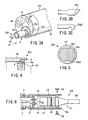
- the treatment member 15b of the horn 15 may be a knife-shaped one 15b1 shown in FIG. 3B or a hook-shaped one shown in FIG. 3C .
- the member 15b may have any other type, nonetheless, so long as it can perform its function.
- FIG. 2 depicts the front b of the treatment member 15b is located at an anti-node of vibration.
- the flange 15a secured to the transducer cover 18 is positioned at a node of vibration.
- the front b of the treatment member 15b is spaced from the flange 15a by a distance of 1/4 wavelength.
- FIG. 4 illustrates how the horn 15 is fitted in the transducer cover 18.
- the flange 15a of the horn 15 is relatively long in the axis of the horn 15.
- the flange 15a has a male screw k cut in its peripheral surface.
- the transducer cover 18 has a female screw m cut in the inner peripheral surface of its distal end portion. The male screw k meshes with the female screw m.
- the flange 15a of the horn 15 is secured to the transducer cover 18.
- the doctor inserts the insertion unit 1B of the endoscope 1 ( FIG. 1 ) into a tubular body cavity of the subject, first the distal end portion 1C3 of the insertion unit 1B.
- the doctor inserts the insertion unit 1B, while observing an image of the body- cavity interior, obtained through the observation lens 13 and displayed on a video monitor. Note that the interior of the body cavity is illuminated with the light applied through the illumination lenses 50.
- the doctor inserts the ultrasonic treatment device 2 into the body cavity through the cap 4b of the operation unit 1A.
- the doctor first inserts the horn 15, then the transducer cover 18 and finally the flexible sheath 3, into the channel 23 through the cap 4b. At this time, the doctor moves the operation unit 6 back and forth, bringing the treatment member 15b on the horn 15 to the affected tissue that should be treated. Then, the doctor moves the operation unit 6 again, causing the treatment member 15b to contact the affected tissue.
- the doctor turns on a switch (not shown) to generate ultrasonic vibration. More precisely, he or she turns on a foot switch or a hand switch. While the switch remains on, a drive signal is supplied from the transducer drive unit 9 via the signal cable 7 to the piezoelectric element 16 of the ultrasonic transducer unit 22A.
- the piezoelectric element 16 converts the drive signal, i.e., an electric signal, to ultrasonic vibration.
- the ultrasonic vibration propagates to the horn 15.
- the treatment member 15b provided at the distal end of the horn 15 applies the ultrasonic vibration to the affected tissue. The tissue is thereby crushed, is emulsified or is coagulated to stop bleeding.
- the ultrasonic treatment device 2 is advantageous in some respects.
- the transducer cover 18 covering the horn 15 and the flexible sheath 3 coupled to the cover 18 have outside diameters smaller than the inside diameter of the channel 23 of the endoscope 1.
- the treatment member 15b provided at the distal end of the horn 15 can protrude from, and receded into, the distal end of the channel 23 as the operation unit 6 is moved back and forth. Therefore, the treatment member 15b can cut or coagulate the living tissue while it is undergoing ultrasonic vibration.
- the doctor can cut or coagulate a living tissue by touching the tissue with the treatment member 15b undergoing ultrasonic vibration.
- the doctor can cut tumors relatively large and tumors not projecting, can cut the blood vessels and can stop bleeding at such tumors and the blood vessels.
- the ultrasonic treatment device 2 can be used to accomplish various medical treatments in body cavities.
- the flexible sheath 3 can be deformed in the same way as the bending portion 1C2 of the endoscope 1, because the ultrasonic transducer unit 22A is coupled to the distal end of the flexible sheath 3 that is a long tube. This makes it possible to bend the portion 1C2 of the endoscope 1 smoothly and makes it easy to project the treatment member 15b from, and pull it into, the distal end portion 1C3 of the endoscope 1.
- the components of the ultrasonic transducer 16A such as the piezoelectric element 16, are not exposed since the hollow cylindrical transducer cover 18 covers all the components of the transducer 16A, except the horn 15. This renders the ultrasonic treatment device 2 safer to the subject.
- FIG. 5 shows a first modification of the ultrasonic transducer unit 22A that is incorporated in the ultrasonic treatment device 2, i.e., the first embodiment of this invention.
- the horn 15 is secured to the transducer cover 18 by laser welding. That is, a laser beam is applied to the interface between the flange 15a and the transducer cover 18, thereby welding the horn 15 to the transducer cover 18.
- the flange 15a has flat surfaces and the cover 18 has flat inner surfaces 18a1 and 18a2. These flat surfaces make it easy to position the horn 15 and the cover 18 with respect to each other in preparation for the laser welding.
- FIG. 6 depicts a second modification of the ultrasonic transducer unit 22A that is incorporated in the ultrasonic treatment device 2, i.e., the first embodiment of this invention.
- the horn 15 is secured to the transducer cover 18 by means of screws. More precisely, screws 54 are driven into the flange 15 though the holes made in the transducer cover 18, thus fastening the flange 15a to the transducer cover 18.
- FIG. 7 depicts a third modification of the ultrasonic transducer unit 22A that is incorporated in the ultrasonic treatment device 2, i.e., the first embodiment of this invention.
- this modified transducer unit 22D the distal end portion of the transducer cover 18 is bent, forming a bent part 18a.
- the bent part 18a is clamped between the horn 15 and the piezoelectric element 16.
- An embedded bolt 25 fastens the horn 15, transducer cover 18, piezoelectric element 16, electrodes 46a and 46b and connecting plate 17 to one another.
- the components of the transducer unit 22D can be fastened together and the transducer cover 18 can be secured, by using one bolt only, i.e., the embedded bolt 25.
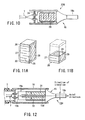
- FIG. 8 shows a fourth modification of the ultrasonic transducer unit 22A that is incorporated in the ultrasonic treatment device 2, i.e., the first embodiment of this invention.
- the horn 15 has a hollow cylindrical cover 15c that is formed integral with the rear end.
- the horn 15 functions not only as a horn, but also as a transducer cover 18. In other words, one component works as two components. This simplifies the structure of the transducer unit.
- the rear end of the hollow cylindrical cover 15c is closed with a shield plate 24.
- the shield plate 24 has two holes that guide the electrically conductive pins 20.
- FIG. 9 illustrates a fifth modification of the ultrasonic transducer unit 22A that is incorporated in the ultrasonic treatment device 2, i.e., the first embodiment of this invention.
- a hollow cylinder 18a is formed integral with the rear end of the transducer cover 18.
- the hollow cylinder 18a extends forwards from the flange 15a the horn 15.
- the distance T between the distal end c of this cylinder 18a and the distal end b of the horn 15 can be adjusted to provide a desired depth of treatment. This meets the demand that the treatment member 15b should be located at a specific depth in some methods of treating affected tissues.
- FIG. 10 shows a sixth modification of the ultrasonic transducer unit 22A that is incorporated in the ultrasonic treatment device 2, i.e., the first embodiment of this invention.
- the horn 15, piezoelectric element 16, electrodes 49a and 49b and connecting plate 17 are fastened together with a bolt, constituting a langevin transducer.
- the sixth modified transducer unit 22G is different in that the piezoelectric element 26 is adhered to the horn 15 as is illustrated in FIG. 10 .
- the sixth modified transducer unit 22G has a more simple structure.
- FIG. 11A shows the multi-layered piezoelectric element 26 used in the sixth modified transducer unit 22G.
- the multi-layered piezoelectric element 26 is composed of one outer electrode 29 and two insulating protective layers 30, which have been formed integral by means of sintering. When supplied with an electric signal, the piezoelectric element 26 vibrates at ultrasonic frequency.
- FIG. 11B depicts another type of a multi-layered piezoelectric element 26 for use in the sixth modified ultrasonic transducer 22G.
- This multi-layered piezoelectric element 26 is composed of a piezoelectric layer 27, one inner electrode 28, one outer electrode 29 and one insulating protective layer 30, which have been formed integral by means of sintering.
- the ultrasonic transducer unit 22A and the modified ultrasonic transducer units 22B to 22G vibrate in their axial direction, performing longitudinal vibration. Other vibration may be more effective than longitudinal vibration in some cases, depending on the shape and condition of the tissue to be treated.
- FIGS. 12 and 13 illustrate a seventh modification 22H of the ultrasonic transducer unit 22A that is incorporated in the ultrasonic treatment device 2, i.e., the first embodiment of this invention.
- the seventh modified transducer unit 22H can vibrate in the direction perpendicular to the axial direction, thus achieving transverse vibration.
- the ultrasonic transducer unit 22H shown in FIGS. 12 and 13 has an element-supporting member 15d integrally formed with the rear end of the horn 15.
- the element-supporting member 15d is shaped like a plate and extends in the axial direction of the horn 15.
- Two vibrators 31 and 32 are mounted on the upper and lower surfaces of the element-supporting member 15d.
- the plate-shaped vibrators 31 and 32 oppose each other across the element-supporting member 15d.
- a negative (-) electrode 31b is interposed between the plate-shaped vibrator 31 and the element-supporting member 15d
- a negative (-) electrode 32a is interposed between the plate-shaped vibrator 32 and the element-supporting member 15d.
- Two positive (+) electrodes 31a and 32b are mounted on the outer surfaces of the vibrators 31 and 32, respectively.
- the plate-shaped vibrators 31 and 32 are therefore polarized in the direction of arrows as illustrated in FIGS. 12 and 13 .
- a negative (-) conductor 19b is connected to the negative (-) electrodes 31b and 32a that contact the element-supporting member 15d.
- a positive (+) conductor 19a is connected to the positive (+) electrodes 31a and 32b that oppose the transducer cover 18.
- the conductors 19a and 19b serve to generate transverse vibration. Transverse vibration works well to crush, for example, stones in body cavities.
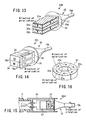
- FIG. 14 shows an eighth modification 22I of the ultrasonic transducer unit 22A that is incorporated in the ultrasonic treatment device 2, i.e., the first embodiment of this invention.
- the eighth modified transducer unit 22I has two multi-layered piezoelectric elements 33 and 34 that are can adhere to the horn 15. As indicated by the arrows in FIG. 14 , the multi-layered piezoelectric elements 33 and 34 are polarized in the opposite directions.
- a positive (+) conductor 19a is connected to one external electrode 35 of the element 33 and one external electrode of the element 34, and a negative (-) conductor 19b is connected to the other external electrode (not shown) of the element 33 and the other external electrode (not shown) of the element 34.
- the modified transducer unit 22I generates transverse vibration.
- FIGS. 15 and 16 show a ninth modification 22J of the ultrasonic transducer unit 22A that is incorporated in the ultrasonic treatment device 2, i.e., the first embodiment of this invention.
- the ninth modified transducer unit 22J has two torsional-vibration transducers 37 that are shaped like a ring.
- each torsional-vibration transducer 37 is composed of segments 37a. It has been made by cutting a ring into segments 37a, polarizing each segment 37a in the direction indicated by an arrow in FIG. 16 , and bonding the segments 37 to each other to form a ring.
- the torsional-vibration transducers 37 are fastened to the horn 15 such that they are polarized in the opposite directions.
- the ninth modified transducer unit 22J can generate torsional vibration in the circumferential direction of the transducers 37.
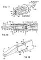
- FIG. 17 illustrates a tenth modification 22K of the ultrasonic transducer unit 22A that is incorporated in the ultrasonic treatment device 2, i.e., the first embodiment of this invention.
- the ninth modified transducer unit 22K has four multi-layered piezoelectric elements 38 to 41.
- the piezoelectric elements 38 to 41 are polarized in the directions of the arrows shown in FIG. 17 .
- the piezoelectric elements 38 to 41 are arranged, opposing one another.
- Four outer electrodes 51 amounted on the piezoelectric elements 38 to 41 are connected to a positive (+) conductor 19a.
- Two negative (-) electrodes 52 interposed, respectively, between the piezoelectric elements 38 and 39 and between the piezoelectric elements 40 and 41. Both negative (-) electrodes 52 are connected to a negative (-) conductor 19b.
- the modified transducer unit 22K can therefore generate vibration.
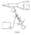
- FIGS. 18 to 20 show a second embodiment of this invention.
- the components that are identical to those of the first embodiment will be designated at the same reference numerals and will not be described. Only the components different from those of the first embodiment will be described.
- the ultrasonic treatment device has a flexible sheath 3, an ultrasonic transducer unit 22L, and a forceps 42.
- the transducer unit 22L is coupled to the distal end of the flexible sheath 3. It has a horn 15, which in turn has a treatment member 15b.
- the forceps 42 is attached to the distal end of the ultrasonic transducer unit 22L.
- the forceps 42 has a holding part 42a, a rear end part 42c, and a supporting part 42b.
- the holding part 42a has a holding surface f that may contact the treatment member 15b of the horn 15.
- the rear end portion 42c is formed integral with the rear end of the holding part 42a.
- the supporting part 42b is provided on one side of the holding part 42a and formed integral with the holding part 42a.
- An operation wire 43 is connected, at one end, to the rear end portion 42c.
- the horn 15 has a hole 44, through which the operation wire 43 passes.
- a cover 15c is formed integral with the rear end of the treatment member 15b. The cover 15c performs the same function as the transducer cover 18 that has been described with reference to FIG. 2 . Note that in the first embodiment, the transducer cover 18 may have a hole through which an operation wire can pass.
- the hole 44 is made in the cover 15c that is integral with the rear end of the treatment member 15b.
- the operation wire 43 passes through the cap 4b of an endoscope 1 and extends to the operation unit 6 of the endoscope 1, as is illustrated in FIG. 20 .
- the operation wire 43 is connected, at proximal end, to a handle 53.
- support pins 45 couples the supporting part 42b of the forceps 42 to the cover 15c of the horn 15, allowing the supporting part 42b to rotate.
- the handle 53 can slide in the axial direction of the shaft portion 6S of the operation unit 6.
- the operation wire 43 moves the rear end portion 42c of the forceps 42 back and forth. So moved, the wire 43 rotates the forceps 42 around the support pins 45, in the direction of the arrows shown in FIG. 19 . As a result, the holding part 42a of the forceps 42 can open and close.
- the doctor inserts the distal end portion 1C3 of the endoscope 1 into the tubular cavity in the subject.
- light is applied to the wall of the cavity from the illumination lenses 50.
- the doctor can observe the interior of the cavity on the video monitor.
- the doctor inserts the ultrasonic treatment device 2 from the cap 4b of an endoscope 1 into the tubular cavity.
- the forceps 42 remains closed, abutting on the treatment member 15b of the horn 15.
- the doctor inserts first the cover 15C and then the flexible sheath 3, from the cap 4b into the channel 23 of the endoscope 1.
- the doctor moves the handle 53 forth, while observing the interior of the cavity through the endoscope 1. After the device 2 enters the cavity, the doctor moves the handle 53 forth further, until the treatment member 15b of the horn 15 abuts on the affected tissue to be treated. Note that the horn 15 is attached to the distal end of the transducer unit 22L.
- the doctor pulls the handle 53 and rotates the handle 53, opening the forceps 42. That is, the holding part 42a of the forceps 42 moves away from the treatment member 15b of the horn 15. Then, the doctor pushes the operation unit 6, maintaining the forceps 42 open. The affected living tissue is thereby clamped between the treatment member 15b and the holding part 42a.
- the doctor turns on the switch (a foot switch or a hand switch) to generate ultrasonic vibration.
- a drive signal is supplied from the transducer drive unit 9 via the signal cable 7 to the piezoelectric element 16 of the ultrasonic transducer unit 22A.
- the piezoelectric element 16 converts the drive signal, i.e., an electric signal, to ultrasonic vibration.
- the ultrasonic vibration propagates to the treatment member 15b of the horn 15.
- the doctor pushes the handle 53, clamping the living tissue between the treatment member 15b and the holding part 42a. Now clamped between the treatment member 15b and the holding part 42a, the living tissue can be crushed, emulsified or coagulated to stop bleeding as the treatment member 15b at the distal end of the horn 15 undergoes ultrasonic vibration.
- the second embodiment is advantageous in some respects.
- the flexible sheath 3 can be deformed in the same way as the bending portion 1C2 of the endoscope 1 is bent, because the ultrasonic transducer unit 22L is coupled to the distal end of the flexible sheath 3. So deformed, the sheath 3 would not hinder the bending of the portion 1C2 of the endoscope 1.
- the treatment member 15b provided at the distal end of the horn 15 can easily protrude from, and receded into, the distal end of the channel 23 as the doctor moves the handle 53 back and forth on the operation unit 6.
- the first embodiment enables the doctor to apply ultrasonic vibration to a living tissue reliably, because the forceps 42 and the treatment member 15b can clamp the living tissue.
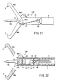
- FIG. 21 and 22 illustrate an ultrasonic treatment device that is a third embodiment of the present invention.
- the components that are identical to those of the first embodiment will be designated at the same reference numerals and will not be described. Only the components different from those of the first embodiment will be described.
- the ultrasonic treatment device i.e., the third embodiment, has a flexible sheath 3, an ultrasonic transducer unit 22M, a transducer cover 18, and two (a pair of) forceps 46a and 46b.
- the ultrasonic transducer unit 22M is coupled to the distal end of the flexible sheath 3.
- the forceps 46a and 46b have a claw g each at the free end. They have rear end parts 46a1 and 46b1, respectively.
- Two support pins 55 couple the rear end part 46a1 and 46b1 to the transducer cover 18, allowing the forceps 46a and 46b to rotate.
- Two operation wires 47 are fastened to the rear end part 46a1 of the forceps 46a and the rear end part 46b1 of the forceps 46b, respectively.
- the wires 47 are inserted into the flexible sheath 3 through the U-notches 48 cut in the transducer cover 18.
- the wires 47 extend through the flexible sheath 3 and are connected to the handle 53 ( FIG. 20 ) provided on the operation unit 6 of an endoscope.
- the handle 53 can slide back and forth on the shaft portion 6S of the operation unit 6.
- the operation wires 47 are moved back and forth.
- the forceps 46a and 46b rotate around the support pins 55 in the opposite directions.
- the claws g at the distal ends of the forceps 46a and 46b can open and close the treatment member 15b.
- the doctor inserts the distal end portion 1C3 of the endoscope 1 into the tubular cavity in the subject.
- light is applied to the wall of the cavity from the illumination lenses 50.
- the doctor can observe the interior of the cavity on the video monitor.
- the doctor inserts the ultrasonic treatment device 2 from the cap 4b of an endoscope 1 into the tubular cavity.
- the forceps 46a and 46b of the device 2 are held in the closed position.
- the doctor inserts the horn 15, the forceps 46a and 46b, the transducer cover 18 and the flexible sheath 3, in the order they are mentioned, from the cap 4b into the channel 23 of the endoscope 1.
- the doctor moves the handle 53 forth, while observing the interior of the cavity through the endoscope 1. After the device 2 enters the cavity, the doctor moves the handle 53 forth further, until the treatment member 15b of the horn 15 abuts on the affected tissue to be treated. It should be noted that the horn 15 is attached to the distal end of the transducer unit 22M.
- the doctor pulls the handle 53 and rotates the handle 53, opening the forceps 46a and 46b. Namely, the forceps 46a and 46b moves away from the treatment member 15b of the horn 15. Then, the doctor pushes the operation unit 6, maintaining the forceps 46a and 46b open. The affected living tissue is thereby clamped between the claws g of the forceps 46a and 46b.
- the doctor After clamping the tissue, the doctor turns on the switch (a foot switch or a hand switch) to generate ultrasonic vibration. Then, a drive signal is supplied from the transducer drive unit 9 via the signal cable 7 to the piezoelectric element 16 of the ultrasonic transducer unit 22A.
- the piezoelectric element 16 converts the drive signal, i.e., an electric signal, to ultrasonic vibration.
- the ultrasonic vibration propagates to the treatment member 15b of the horn 15.
- the doctor further pulls the handle 53, squeezing the living tissue between the claws g of the forceps 46a and 46b.
- the living tissue can be cut or coagulated to stop bleeding as the treatment member 15b undergoes ultrasonic vibration.
- the second embodiment is advantageous in some respects.
- the flexible sheath 3 can be deformed in the same way as the bending portion 1C2 of the endoscope 1 is bent, because the ultrasonic transducer unit 22M is coupled to the distal end of the flexible sheath 3. So deformed, the sheath 3 would not hinder the bending of the portion 1C2 of the endoscope 1.
- the treatment member 15b provided at the distal end of the horn 15 of the unit 22M can easily protrude from, and receded into, the distal end portion 1C3 of the endoscope 1 as the doctor moves the handle 53 back and forth on the operation unit 6.
- the third embodiment makes it easier for the doctor to perform ultrasonic treatment on the living tissue as is desired.
Landscapes
- Health & Medical Sciences (AREA)
- Surgery (AREA)
- Engineering & Computer Science (AREA)
- Life Sciences & Earth Sciences (AREA)
- Biomedical Technology (AREA)
- Molecular Biology (AREA)
- Vascular Medicine (AREA)
- Orthopedic Medicine & Surgery (AREA)
- Mechanical Engineering (AREA)
- Heart & Thoracic Surgery (AREA)
- Medical Informatics (AREA)
- Nuclear Medicine, Radiotherapy & Molecular Imaging (AREA)
- Animal Behavior & Ethology (AREA)
- General Health & Medical Sciences (AREA)
- Public Health (AREA)
- Veterinary Medicine (AREA)
- Surgical Instruments (AREA)
- Ultra Sonic Daignosis Equipment (AREA)
Claims (16)
- Ultraschall-Behandlungsgerät, mit:einer Ultraschallwandlereinheit (22A, 22B, 22C, 22D, 22E, 22F, 22G, 22H, 22I, 22J, 22K, 22L, 22M), die einen Ultraschallwandler (16A) und ein Abdeckelement (18) hat, das den Ultraschallwandler (16A) abdeckt;einem flexiblen Mantel (3) mit einem distalen Endteil und einem proximalen Endteil, wobei das distale Endteil mit dem Abdeckelement (18) gekoppelt ist;einem Signalkabel (7), das durch den Mantel (3) verläuft und ein distales Endteil sowie ein proximales Endteil hat, wobei das distale Endteil mit dem Ultraschallwandler (16A) verbunden ist;einer Wandler-Treibereinheit (9), die mit dem proximalen Endteil des Signalkabels (7) verbunden und so konfiguriert ist, dass sie ein Steuersignal zum Ansteuern des Ultraschallwandlers (16A) erzeugt;einer Bedienungseinheit (6), die am proximalen Endteil des Mantels (3) vorgesehen und so konfiguriert ist, dass sie bei Betätigung durch einen Arzt die Ultraschallwandlereinheit (22A bis 22M) in axialer Richtung des Mantels (3) bewegt.
- Gerät nach Anspruch 1, dadurch gekennzeichnet, dass:der Ultraschallwandler (16A) eine Achse, ein Hauptteil (16), ein Horn (15) und ein Behandlungselement (15b) hat, wobei das Horn (15) einen distalen Endteil und einen proximalen Endteil hat, das mit dem Hauptteil (16) gekoppelt und so konfiguriert ist,dass es Ultraschallschwingung, die vom Hauptteil (16) erzeugt wird, verstärkt, mit der das distale Endteil beaufschlagt wird, wobei das Behandlungselement (15b) am distalen Endteil des Horns (15) bereitgestellt ist, um auf lebendem Gewebe aufzuliegen und um eine Ultraschallbehandlung des lebenden Gewebes auszuführen; unddie Ultraschallwandlereinheit (22A bis 22M) ein Befestigungselement (15a) hat, das das Abdeckelement (18) an einem Schwingungsknoten des Ultraschallwandlers (16A) sichert.
- Gerät nach Anspruch 2, dadurch gekennzeichnet, dass sich das Behandlungselement (15b) in einem 1/4-Wellenlängenabstand vom Befestigungselement (15a) befindet, das das Abdeckelement (18) sichert.
- Gerät nach Anspruch 2, dadurch gekennzeichnet, dass:das Hauptteil (16) des Ultraschallwandlers (16A) eine Mehrzahl piezoelektrischer Elemente (16), die ein elektrisches Signal in eine mechanische Schwingung wandeln,eine Mehrzahl Elektroden (49a, 49b), die ein elektrisches Signal an die piezoelektrischen Elemente (16) liefert, und eine Verbindungsplatte (17) aufweist;das Abdeckelement (18) am Schwingungsknoten des Ultraschallwandler (16A) positioniert und zwischen dem Horn (15) und den piezoelektrischen Elementen (16) angeordnet ist; unddie Ultraschallwandlereinheit (22A bis 22M) einen eingebetteten Bolzen (25) hat, der das Abdeckelement (18), die piezoelektrischen Elemente (16), die Elektroden (49a, 49b) und die Verbindungsplatte (17) aneinander befestigt.
- Gerät nach Anspruch 2, dadurch gekennzeichnet, dass das Horn (15) und das Abdeckelement (18) in der Ultraschallwandlereinheit (22A bis 22M) integral miteinander ausgebildet sind.
- Gerät nach Anspruch 2, dadurch gekennzeichnet, dass das Hauptteil (16) des Ultraschallwandlers (16A) piezoelektrische Schichten (27), innere Elektroden (28) und äußere Elektroden (29) hat, die abwechselnd übereinander liegen.
- Gerät nach Anspruch 2, dadurch gekennzeichnet, dass der Ultraschallwandler (16A) ein Hauptteil (16) hat, bei dem es sich um einen Transversalvibrator handelt, der in einer Richtung senkrecht zur Achse des Ultraschallwandlers (16A) schwingt.
- Gerät nach Anspruch 2, dadurch gekennzeichnet, dass der Ultraschallwandler (16A) ein Torsionsschwingungs-Hauptteil (16) hat, das in einem Kreis um die Achse schwingt.
- Gerät nach Anspruch 1, dadurch gekennzeichnet, dass das Signalkabel (7) am proximalen Endteil einen Steckverbinder (8) hat, wobei der Steckverbinder (8) mit der Wandler-Treibereinheit (9) verbunden werden kann.
- Gerät nach Anspruch 1, dadurch gekennzeichnet, dass die Bedienungseinheit (6) einen Kabelführungskanal (4b) hat, durch den das Signalkabel (7) geführt wird, und das so geführte Signalkabel (7) wird mit der Wandler-Treibereinheit (9) verbunden.
- Gerät nach Anspruch 10, dadurch gekennzeichnet, dass das Signalkabel (7) einen Steckverbinder (8) an einem Endteil hat, der aus dem Kabelführungskanal (4b) herausragt, so dass der Steckverbinder (8) mit der Wandler-Treibereinheit (9) verbunden werden kann.
- Gerät nach Anspruch 2, dadurch gekennzeichnet, dass:die Ultraschallwandlereinheit (22L) ein Zangenelement (42) hat, das drehbar mit dem Abdeckelement (18) gekoppelt ist;das Zangenelement (42) Lagerstifte (45) hat, die drehbar am Abdeckelement (18) gelagert sind, und ein Halteteil (42a), das mit dem Horn (15) in Kontakt und außer Kontakt kommt, wenn es um die Lagerstifte (54) gedreht wird;ein Betätigungsdraht durch den flexiblen Mantel (3) verläuft, um das Zangenelement (42) zu betätigen, und ein proximales sowie ein distales Endteil hat, das mit dem Zangenelement (42) verbunden ist; unddie Betätigungseinheit (6) einen Führungsabschnitt (6S) hat, der sich in axialer Richtung des Betätigungsdrahtes (43) erstreckt, und einen Griff (53), der am Führungsabschnitt (6S) angebracht ist, um vorwärts und rückwärts bewegt zu werden, und der mit dem proximalen Endteil des Betätigungsdrahtes (43) verbunden ist, um den Betätigungsdraht (43) zu spannen und zu entspannen, wodurch sich das Zangenelement (43) zum Horn (15) und vom Horn weg bewegt.
- Gerät nach Anspruch 5, dadurch gekennzeichnet, dass das Signalkabel (7) einen Steckverbinder (8) am proximalen Endteil hat, wobei der Steckverbinder (8) mit der Wandler-Treibereinheit (9) verbunden werden kann.
- Gerät nach Anspruch 12, dadurch gekennzeichnet, dass das Zangenelement (42) so bewegt werden kann, dass es lebendes Gewebe zwischen dem Halteteil (42a) und dem proximalen Endteil des Horns (15) fassen kann.
- Gerät nach Anspruch 12, dadurch gekennzeichnet, dass:die Ultraschallwandlereinheit (22M) ein Paar Zangenelemente (46a, 46b) hat, die jeweils an zwei Seiten des Horns (15) angeordnet und drehbar mit dem Abdeckelement (18) gekoppelt sind;die Zangenelemente (46a, 46b) jeweils einen Lagerstift (55) und ein Halteteil (g) haben, wobei der Lagerstift (55) drehbar mit dem Abdeckelement (18) und dem Halteteil (g) gekoppelt ist, das mit dem Horn (15) in Kontakt und außer Kontakt kommt, wenn die Zangenelemente (46a, 46b) um den Lagerstift (55) gedreht werden; undjedes der Zangenelemente (46a, 46b) so bewegt werden kann, dass lebendes Gewebe zwischen dem Halteteil (g) und dem Horn (15) gefasst wird.
- Ultraschall-Behandlungssystem mit einem Ultraschall-Behandlungsgerät (2) und einem Endoskop (1), das zusammen mit dem Ultraschall-Behandlungsgerät (2) verwendet wird, wobei das Ultraschall-Behandlungsgerät (2) aufweist:eine Ultraschallwandlereinheit (22A bis 22M), die einen Ultraschallwandler (16A), der zum Behandeln von lebendem Gewebe konzipiert ist, und ein Abdeckelement (18), das den Ultraschallwandler (16A) abdeckt, hat;einen flexiblen Mantel (3) mit einem distalen Endteil und einem proximalen Endteil, wobei das distale Endteil mit dem Abdeckelement (18) gekoppelt ist;ein Signalkabel (7), das durch den Mantel (3) verläuft und ein distales Endteil sowie ein proximales Endteil hat, wobei das distale Endteil mit dem Ultraschallwandler (16A) verbunden ist;eine Wandler-Treibereinheit (9), die mit dem proximalen Endteil des Signalkabels (7) verbunden und so konfiguriert ist, dass sie ein Steuersignal zum Ansteuern des Ultraschallwandlers (16A) erzeugt;eine Bedienungseinheit (6), die am proximalen Endteil des Mantels (3) vorgesehen und so konfiguriert ist, dass sie die Ultraschallwandlereinheit (22A bis 22M) in axialer Richtung des Mantels (3) bewegt,wobei das Endoskop (1) eine langgestreckte Einführeinheit (1B) enthält, die in einen Körperhohlraum einzuführen ist und mindestens einen Kanal (23) hat, das Abdeckelement (18) und der flexible Mantel (3) des Ultraschall-Behandlungsgeräts (2) Außendurchmesser haben, die kleiner sind als der Innendurchmesser des Kanals (23) des Endoskops (1), und die Ultraschallwandlereinheit (22A bis 22M) so konfiguriert ist, dass sie sich in den und aus dem Kanal (23) des Endoskops (1) bewegt, wenn die Betätigungseinheit (6) in axialer Richtung das Mantels (3) bewegt wird.
Applications Claiming Priority (2)
| Application Number | Priority Date | Filing Date | Title |
|---|---|---|---|
| JP2003304709 | 2003-08-28 | ||
| JP2003304709A JP3999715B2 (ja) | 2003-08-28 | 2003-08-28 | 超音波処置装置 |
Publications (2)
| Publication Number | Publication Date |
|---|---|
| EP1510178A1 EP1510178A1 (de) | 2005-03-02 |
| EP1510178B1 true EP1510178B1 (de) | 2011-06-08 |
Family
ID=34101222
Family Applications (1)
| Application Number | Title | Priority Date | Filing Date |
|---|---|---|---|
| EP04020181A Expired - Lifetime EP1510178B1 (de) | 2003-08-28 | 2004-08-25 | Ultraschallgerät und Ultraschall-Behandlungssystem |
Country Status (4)
| Country | Link |
|---|---|
| US (1) | US7449004B2 (de) |
| EP (1) | EP1510178B1 (de) |
| JP (1) | JP3999715B2 (de) |
| AT (1) | ATE511802T1 (de) |
Cited By (104)
| Publication number | Priority date | Publication date | Assignee | Title |
|---|---|---|---|---|
| US9066747B2 (en) | 2007-11-30 | 2015-06-30 | Ethicon Endo-Surgery, Inc. | Ultrasonic surgical instrument blades |
| US9095367B2 (en) | 2012-10-22 | 2015-08-04 | Ethicon Endo-Surgery, Inc. | Flexible harmonic waveguides/blades for surgical instruments |
| US9107689B2 (en) | 2010-02-11 | 2015-08-18 | Ethicon Endo-Surgery, Inc. | Dual purpose surgical instrument for cutting and coagulating tissue |
| US9198714B2 (en) | 2012-06-29 | 2015-12-01 | Ethicon Endo-Surgery, Inc. | Haptic feedback devices for surgical robot |
| US9220527B2 (en) | 2007-07-27 | 2015-12-29 | Ethicon Endo-Surgery, Llc | Surgical instruments |
| US9226766B2 (en) | 2012-04-09 | 2016-01-05 | Ethicon Endo-Surgery, Inc. | Serial communication protocol for medical device |
| US9226767B2 (en) | 2012-06-29 | 2016-01-05 | Ethicon Endo-Surgery, Inc. | Closed feedback control for electrosurgical device |
| US9232979B2 (en) | 2012-02-10 | 2016-01-12 | Ethicon Endo-Surgery, Inc. | Robotically controlled surgical instrument |
| US9237921B2 (en) | 2012-04-09 | 2016-01-19 | Ethicon Endo-Surgery, Inc. | Devices and techniques for cutting and coagulating tissue |
| US9241731B2 (en) | 2012-04-09 | 2016-01-26 | Ethicon Endo-Surgery, Inc. | Rotatable electrical connection for ultrasonic surgical instruments |
| US9241728B2 (en) | 2013-03-15 | 2016-01-26 | Ethicon Endo-Surgery, Inc. | Surgical instrument with multiple clamping mechanisms |
| US9283045B2 (en) | 2012-06-29 | 2016-03-15 | Ethicon Endo-Surgery, Llc | Surgical instruments with fluid management system |
| US9326788B2 (en) | 2012-06-29 | 2016-05-03 | Ethicon Endo-Surgery, Llc | Lockout mechanism for use with robotic electrosurgical device |
| US9351754B2 (en) | 2012-06-29 | 2016-05-31 | Ethicon Endo-Surgery, Llc | Ultrasonic surgical instruments with distally positioned jaw assemblies |
| US9393037B2 (en) | 2012-06-29 | 2016-07-19 | Ethicon Endo-Surgery, Llc | Surgical instruments with articulating shafts |
| US9408622B2 (en) | 2012-06-29 | 2016-08-09 | Ethicon Endo-Surgery, Llc | Surgical instruments with articulating shafts |
| US9414853B2 (en) | 2007-07-27 | 2016-08-16 | Ethicon Endo-Surgery, Llc | Ultrasonic end effectors with increased active length |
| US9427249B2 (en) | 2010-02-11 | 2016-08-30 | Ethicon Endo-Surgery, Llc | Rotatable cutting implements with friction reducing material for ultrasonic surgical instruments |
| US9439669B2 (en) | 2007-07-31 | 2016-09-13 | Ethicon Endo-Surgery, Llc | Ultrasonic surgical instruments |
| US9439668B2 (en) | 2012-04-09 | 2016-09-13 | Ethicon Endo-Surgery, Llc | Switch arrangements for ultrasonic surgical instruments |
| US9445832B2 (en) | 2007-07-31 | 2016-09-20 | Ethicon Endo-Surgery, Llc | Surgical instruments |
| US9498245B2 (en) | 2009-06-24 | 2016-11-22 | Ethicon Endo-Surgery, Llc | Ultrasonic surgical instruments |
| US9504855B2 (en) | 2008-08-06 | 2016-11-29 | Ethicon Surgery, LLC | Devices and techniques for cutting and coagulating tissue |
| US9504483B2 (en) | 2007-03-22 | 2016-11-29 | Ethicon Endo-Surgery, Llc | Surgical instruments |
| US9510850B2 (en) | 2010-02-11 | 2016-12-06 | Ethicon Endo-Surgery, Llc | Ultrasonic surgical instruments |
| US9554846B2 (en) | 2010-10-01 | 2017-01-31 | Ethicon Endo-Surgery, Llc | Surgical instrument with jaw member |
| US9554854B2 (en) | 2014-03-18 | 2017-01-31 | Ethicon Endo-Surgery, Llc | Detecting short circuits in electrosurgical medical devices |
| US9623237B2 (en) | 2009-10-09 | 2017-04-18 | Ethicon Endo-Surgery, Llc | Surgical generator for ultrasonic and electrosurgical devices |
| US9636135B2 (en) | 2007-07-27 | 2017-05-02 | Ethicon Endo-Surgery, Llc | Ultrasonic surgical instruments |
| US9649126B2 (en) | 2010-02-11 | 2017-05-16 | Ethicon Endo-Surgery, Llc | Seal arrangements for ultrasonically powered surgical instruments |
| US9700333B2 (en) | 2014-06-30 | 2017-07-11 | Ethicon Llc | Surgical instrument with variable tissue compression |
| US9700339B2 (en) | 2009-05-20 | 2017-07-11 | Ethicon Endo-Surgery, Inc. | Coupling arrangements and methods for attaching tools to ultrasonic surgical instruments |
| US9707027B2 (en) | 2010-05-21 | 2017-07-18 | Ethicon Endo-Surgery, Llc | Medical device |
| US9724118B2 (en) | 2012-04-09 | 2017-08-08 | Ethicon Endo-Surgery, Llc | Techniques for cutting and coagulating tissue for ultrasonic surgical instruments |
| US9737355B2 (en) | 2014-03-31 | 2017-08-22 | Ethicon Llc | Controlling impedance rise in electrosurgical medical devices |
| US9757186B2 (en) | 2014-04-17 | 2017-09-12 | Ethicon Llc | Device status feedback for bipolar tissue spacer |
| US9764164B2 (en) | 2009-07-15 | 2017-09-19 | Ethicon Llc | Ultrasonic surgical instruments |
| US9801648B2 (en) | 2007-03-22 | 2017-10-31 | Ethicon Llc | Surgical instruments |
| US9808308B2 (en) | 2010-04-12 | 2017-11-07 | Ethicon Llc | Electrosurgical cutting and sealing instruments with cam-actuated jaws |
| US9820768B2 (en) | 2012-06-29 | 2017-11-21 | Ethicon Llc | Ultrasonic surgical instruments with control mechanisms |
| US9848937B2 (en) | 2014-12-22 | 2017-12-26 | Ethicon Llc | End effector with detectable configurations |
| US9848902B2 (en) | 2007-10-05 | 2017-12-26 | Ethicon Llc | Ergonomic surgical instruments |
| US9872725B2 (en) | 2015-04-29 | 2018-01-23 | Ethicon Llc | RF tissue sealer with mode selection |
| US9877776B2 (en) | 2014-08-25 | 2018-01-30 | Ethicon Llc | Simultaneous I-beam and spring driven cam jaw closure mechanism |
| US9883884B2 (en) | 2007-03-22 | 2018-02-06 | Ethicon Llc | Ultrasonic surgical instruments |
| US9913680B2 (en) | 2014-04-15 | 2018-03-13 | Ethicon Llc | Software algorithms for electrosurgical instruments |
| US9949788B2 (en) | 2013-11-08 | 2018-04-24 | Ethicon Endo-Surgery, Llc | Electrosurgical devices |
| US9962182B2 (en) | 2010-02-11 | 2018-05-08 | Ethicon Llc | Ultrasonic surgical instruments with moving cutting implement |
| US10010339B2 (en) | 2007-11-30 | 2018-07-03 | Ethicon Llc | Ultrasonic surgical blades |
| US10034704B2 (en) | 2015-06-30 | 2018-07-31 | Ethicon Llc | Surgical instrument with user adaptable algorithms |
| US10034684B2 (en) | 2015-06-15 | 2018-07-31 | Ethicon Llc | Apparatus and method for dissecting and coagulating tissue |
| US10092348B2 (en) | 2014-12-22 | 2018-10-09 | Ethicon Llc | RF tissue sealer, shear grip, trigger lock mechanism and energy activation |
| US10092310B2 (en) | 2014-03-27 | 2018-10-09 | Ethicon Llc | Electrosurgical devices |
| US10111699B2 (en) | 2014-12-22 | 2018-10-30 | Ethicon Llc | RF tissue sealer, shear grip, trigger lock mechanism and energy activation |
| US10117702B2 (en) | 2015-04-10 | 2018-11-06 | Ethicon Llc | Surgical generator systems and related methods |
| US10130410B2 (en) | 2015-04-17 | 2018-11-20 | Ethicon Llc | Electrosurgical instrument including a cutting member decouplable from a cutting member trigger |
| US10154852B2 (en) | 2015-07-01 | 2018-12-18 | Ethicon Llc | Ultrasonic surgical blade with improved cutting and coagulation features |
| US10159524B2 (en) | 2014-12-22 | 2018-12-25 | Ethicon Llc | High power battery powered RF amplifier topology |
| US10166060B2 (en) | 2011-08-30 | 2019-01-01 | Ethicon Llc | Surgical instruments comprising a trigger assembly |
| US10172669B2 (en) | 2009-10-09 | 2019-01-08 | Ethicon Llc | Surgical instrument comprising an energy trigger lockout |
| US10179022B2 (en) | 2015-12-30 | 2019-01-15 | Ethicon Llc | Jaw position impedance limiter for electrosurgical instrument |
| US10194973B2 (en) | 2015-09-30 | 2019-02-05 | Ethicon Llc | Generator for digitally generating electrical signal waveforms for electrosurgical and ultrasonic surgical instruments |
| US10194976B2 (en) | 2014-08-25 | 2019-02-05 | Ethicon Llc | Lockout disabling mechanism |
| US10194972B2 (en) | 2014-08-26 | 2019-02-05 | Ethicon Llc | Managing tissue treatment |
| US10201382B2 (en) | 2009-10-09 | 2019-02-12 | Ethicon Llc | Surgical generator for ultrasonic and electrosurgical devices |
| US10201365B2 (en) | 2012-10-22 | 2019-02-12 | Ethicon Llc | Surgeon feedback sensing and display methods |
| US10226273B2 (en) | 2013-03-14 | 2019-03-12 | Ethicon Llc | Mechanical fasteners for use with surgical energy devices |
| US10245064B2 (en) | 2016-07-12 | 2019-04-02 | Ethicon Llc | Ultrasonic surgical instrument with piezoelectric central lumen transducer |
| US10251664B2 (en) | 2016-01-15 | 2019-04-09 | Ethicon Llc | Modular battery powered handheld surgical instrument with multi-function motor via shifting gear assembly |
| US10278721B2 (en) | 2010-07-22 | 2019-05-07 | Ethicon Llc | Electrosurgical instrument with separate closure and cutting members |
| USD847990S1 (en) | 2016-08-16 | 2019-05-07 | Ethicon Llc | Surgical instrument |
| US10285724B2 (en) | 2014-07-31 | 2019-05-14 | Ethicon Llc | Actuation mechanisms and load adjustment assemblies for surgical instruments |
| US10285723B2 (en) | 2016-08-09 | 2019-05-14 | Ethicon Llc | Ultrasonic surgical blade with improved heel portion |
| US10314638B2 (en) | 2015-04-07 | 2019-06-11 | Ethicon Llc | Articulating radio frequency (RF) tissue seal with articulating state sensing |
| US10321950B2 (en) | 2015-03-17 | 2019-06-18 | Ethicon Llc | Managing tissue treatment |
| US10342602B2 (en) | 2015-03-17 | 2019-07-09 | Ethicon Llc | Managing tissue treatment |
| US10357303B2 (en) | 2015-06-30 | 2019-07-23 | Ethicon Llc | Translatable outer tube for sealing using shielded lap chole dissector |
| US10376305B2 (en) | 2016-08-05 | 2019-08-13 | Ethicon Llc | Methods and systems for advanced harmonic energy |
| US10420580B2 (en) | 2016-08-25 | 2019-09-24 | Ethicon Llc | Ultrasonic transducer for surgical instrument |
| US10433900B2 (en) | 2011-07-22 | 2019-10-08 | Ethicon Llc | Surgical instruments for tensioning tissue |
| US10441345B2 (en) | 2009-10-09 | 2019-10-15 | Ethicon Llc | Surgical generator for ultrasonic and electrosurgical devices |
| US10456193B2 (en) | 2016-05-03 | 2019-10-29 | Ethicon Llc | Medical device with a bilateral jaw configuration for nerve stimulation |
| US10463421B2 (en) | 2014-03-27 | 2019-11-05 | Ethicon Llc | Two stage trigger, clamp and cut bipolar vessel sealer |
| US10485607B2 (en) | 2016-04-29 | 2019-11-26 | Ethicon Llc | Jaw structure with distal closure for electrosurgical instruments |
| US10524854B2 (en) | 2010-07-23 | 2020-01-07 | Ethicon Llc | Surgical instrument |
| US10524852B1 (en) | 2014-03-28 | 2020-01-07 | Ethicon Llc | Distal sealing end effector with spacers |
| US10537352B2 (en) | 2004-10-08 | 2020-01-21 | Ethicon Llc | Tissue pads for use with surgical instruments |
| US10555769B2 (en) | 2016-02-22 | 2020-02-11 | Ethicon Llc | Flexible circuits for electrosurgical instrument |
| US10575892B2 (en) | 2015-12-31 | 2020-03-03 | Ethicon Llc | Adapter for electrical surgical instruments |
| US10595930B2 (en) | 2015-10-16 | 2020-03-24 | Ethicon Llc | Electrode wiping surgical device |
| US10595929B2 (en) | 2015-03-24 | 2020-03-24 | Ethicon Llc | Surgical instruments with firing system overload protection mechanisms |
| US10639092B2 (en) | 2014-12-08 | 2020-05-05 | Ethicon Llc | Electrode configurations for surgical instruments |
| US10646269B2 (en) | 2016-04-29 | 2020-05-12 | Ethicon Llc | Non-linear jaw gap for electrosurgical instruments |
| USRE47996E1 (en) | 2009-10-09 | 2020-05-19 | Ethicon Llc | Surgical generator for ultrasonic and electrosurgical devices |
| US10702329B2 (en) | 2016-04-29 | 2020-07-07 | Ethicon Llc | Jaw structure with distal post for electrosurgical instruments |
| US10751117B2 (en) | 2016-09-23 | 2020-08-25 | Ethicon Llc | Electrosurgical instrument with fluid diverter |
| US10842522B2 (en) | 2016-07-15 | 2020-11-24 | Ethicon Llc | Ultrasonic surgical instruments having offset blades |
| US10881449B2 (en) | 2012-09-28 | 2021-01-05 | Ethicon Llc | Multi-function bi-polar forceps |
| US10893883B2 (en) | 2016-07-13 | 2021-01-19 | Ethicon Llc | Ultrasonic assembly for use with ultrasonic surgical instruments |
| US10959806B2 (en) | 2015-12-30 | 2021-03-30 | Ethicon Llc | Energized medical device with reusable handle |
| US11020140B2 (en) | 2015-06-17 | 2021-06-01 | Cilag Gmbh International | Ultrasonic surgical blade for use with ultrasonic surgical instruments |
| US11058447B2 (en) | 2007-07-31 | 2021-07-13 | Cilag Gmbh International | Temperature controlled ultrasonic surgical instruments |
| US11266430B2 (en) | 2016-11-29 | 2022-03-08 | Cilag Gmbh International | End effector control and calibration |
| US11324527B2 (en) | 2012-11-15 | 2022-05-10 | Cilag Gmbh International | Ultrasonic and electrosurgical devices |
Families Citing this family (89)
| Publication number | Priority date | Publication date | Assignee | Title |
|---|---|---|---|---|
| US11229472B2 (en) | 2001-06-12 | 2022-01-25 | Cilag Gmbh International | Modular battery powered handheld surgical instrument with multiple magnetic position sensors |
| US8182501B2 (en) | 2004-02-27 | 2012-05-22 | Ethicon Endo-Surgery, Inc. | Ultrasonic surgical shears and method for sealing a blood vessel using same |
| US20060116610A1 (en) * | 2004-11-30 | 2006-06-01 | Omnisonics Medical Technologies, Inc. | Apparatus and method for an ultrasonic medical device with variable frequency drive |
| US20070191713A1 (en) | 2005-10-14 | 2007-08-16 | Eichmann Stephen E | Ultrasonic device for cutting and coagulating |
| US7621930B2 (en) | 2006-01-20 | 2009-11-24 | Ethicon Endo-Surgery, Inc. | Ultrasound medical instrument having a medical ultrasonic blade |
| JP5165696B2 (ja) * | 2007-01-16 | 2013-03-21 | エシコン・エンド−サージェリィ・インコーポレイテッド | 切断および凝固用超音波装置 |
| JP2008264253A (ja) * | 2007-04-20 | 2008-11-06 | Olympus Medical Systems Corp | 医療用処置具及び内視鏡処置システム |
| US20090044880A1 (en) * | 2007-06-16 | 2009-02-19 | Jody Jones | Log cutting |
| US8187168B2 (en) * | 2007-07-09 | 2012-05-29 | David George Wuchinich | Retractable ultrasonic endoscopic aspirator |
| US8974477B2 (en) * | 2008-08-29 | 2015-03-10 | Olympus Medical Systems Corp. | Ultrasonic operating apparatus |
| US11090104B2 (en) | 2009-10-09 | 2021-08-17 | Cilag Gmbh International | Surgical generator for ultrasonic and electrosurgical devices |
| US8376970B2 (en) * | 2009-10-29 | 2013-02-19 | Eilaz Babaev | Ultrasound apparatus and methods for mitigation of neurological damage |
| JP5851147B2 (ja) * | 2011-08-05 | 2016-02-03 | オリンパス株式会社 | 超音波振動装置 |
| US10085762B2 (en) * | 2011-10-21 | 2018-10-02 | Ethicon Llc | Ultrasonic device for cutting and coagulating |
| US9414880B2 (en) | 2011-10-24 | 2016-08-16 | Ethicon Endo-Surgery, Llc | User interface in a battery powered device |
| JP5911259B2 (ja) * | 2011-10-24 | 2016-04-27 | オリンパス株式会社 | 超音波振動装置 |
| US20140005705A1 (en) | 2012-06-29 | 2014-01-02 | Ethicon Endo-Surgery, Inc. | Surgical instruments with articulating shafts |
| US20140005702A1 (en) | 2012-06-29 | 2014-01-02 | Ethicon Endo-Surgery, Inc. | Ultrasonic surgical instruments with distally positioned transducers |
| US20140081299A1 (en) * | 2012-09-19 | 2014-03-20 | Timothy G. Dietz | Micromachined Ultrasonic Scalpel with Embedded Piezoelectric Actuator |
| DE102012219354A1 (de) * | 2012-10-23 | 2014-04-24 | Olympus Winter & Ibe Gmbh | Aktuator für ein chirurgisches Instrument |
| US10265119B2 (en) * | 2013-02-15 | 2019-04-23 | Covidien Lp | Electrosurgical forceps |
| EP3017878A4 (de) * | 2013-07-03 | 2017-03-15 | Olympus Corporation | Ultraschallvibrationsvorrichtung, herstellungsverfahren für die ultraschallvibrationsvorrichtung und medizinische ultraschallvorrichtung |
| DE102013011964A1 (de) * | 2013-07-15 | 2015-01-15 | SRH Wald-Klinikum Gera gGmbH | Anordnung und Verfahren zur in-vitro und in-vivo- Behandlung von Lungentumoren |
| GB201315755D0 (en) * | 2013-09-04 | 2013-10-16 | Univ Glasgow | Device and method for causing aggregation of blood cells and method of treating bleeding from an injury. |
| US9814514B2 (en) | 2013-09-13 | 2017-11-14 | Ethicon Llc | Electrosurgical (RF) medical instruments for cutting and coagulating tissue |
| GB2521228A (en) | 2013-12-16 | 2015-06-17 | Ethicon Endo Surgery Inc | Medical device |
| GB2521229A (en) | 2013-12-16 | 2015-06-17 | Ethicon Endo Surgery Inc | Medical device |
| US9795436B2 (en) | 2014-01-07 | 2017-10-24 | Ethicon Llc | Harvesting energy from a surgical generator |
| WO2016051486A1 (ja) * | 2014-09-30 | 2016-04-07 | オリンパス株式会社 | 超音波振動子及び超音波医療装置 |
| US10245095B2 (en) | 2015-02-06 | 2019-04-02 | Ethicon Llc | Electrosurgical instrument with rotation and articulation mechanisms |
| US11129669B2 (en) | 2015-06-30 | 2021-09-28 | Cilag Gmbh International | Surgical system with user adaptable techniques based on tissue type |
| US11141213B2 (en) | 2015-06-30 | 2021-10-12 | Cilag Gmbh International | Surgical instrument with user adaptable techniques |
| US10898256B2 (en) | 2015-06-30 | 2021-01-26 | Ethicon Llc | Surgical system with user adaptable techniques based on tissue impedance |
| US11051873B2 (en) | 2015-06-30 | 2021-07-06 | Cilag Gmbh International | Surgical system with user adaptable techniques employing multiple energy modalities based on tissue parameters |
| US9913570B2 (en) | 2015-08-07 | 2018-03-13 | Enlightenvue Llc | Endoscope with variable profile tip |
| US10959771B2 (en) | 2015-10-16 | 2021-03-30 | Ethicon Llc | Suction and irrigation sealing grasper |
| EP3313301A1 (de) * | 2015-10-23 | 2018-05-02 | Boston Scientific Scimed, Inc. | Ultraschallbehandlungsvorrichtungen und systeme |
| US11229471B2 (en) | 2016-01-15 | 2022-01-25 | Cilag Gmbh International | Modular battery powered handheld surgical instrument with selective application of energy based on tissue characterization |
| US10716615B2 (en) | 2016-01-15 | 2020-07-21 | Ethicon Llc | Modular battery powered handheld surgical instrument with curved end effectors having asymmetric engagement between jaw and blade |
| US12193698B2 (en) | 2016-01-15 | 2025-01-14 | Cilag Gmbh International | Method for self-diagnosing operation of a control switch in a surgical instrument system |
| US11129670B2 (en) | 2016-01-15 | 2021-09-28 | Cilag Gmbh International | Modular battery powered handheld surgical instrument with selective application of energy based on button displacement, intensity, or local tissue characterization |
| US10856934B2 (en) | 2016-04-29 | 2020-12-08 | Ethicon Llc | Electrosurgical instrument with electrically conductive gap setting and tissue engaging members |
| US10987156B2 (en) | 2016-04-29 | 2021-04-27 | Ethicon Llc | Electrosurgical instrument with electrically conductive gap setting member and electrically insulative tissue engaging members |
| US10543013B2 (en) | 2016-05-19 | 2020-01-28 | Ethicon Llc | Passive dissection features for ultrasonic surgical instrument |
| US10952759B2 (en) | 2016-08-25 | 2021-03-23 | Ethicon Llc | Tissue loading of a surgical instrument |
| US10603064B2 (en) | 2016-11-28 | 2020-03-31 | Ethicon Llc | Ultrasonic transducer |
| US11033325B2 (en) | 2017-02-16 | 2021-06-15 | Cilag Gmbh International | Electrosurgical instrument with telescoping suction port and debris cleaner |
| US10799284B2 (en) | 2017-03-15 | 2020-10-13 | Ethicon Llc | Electrosurgical instrument with textured jaws |
| US11497546B2 (en) | 2017-03-31 | 2022-11-15 | Cilag Gmbh International | Area ratios of patterned coatings on RF electrodes to reduce sticking |
| US10603117B2 (en) | 2017-06-28 | 2020-03-31 | Ethicon Llc | Articulation state detection mechanisms |
| CA3075487A1 (en) * | 2017-06-30 | 2019-01-03 | Enlightenvue Llc | Endoscopy systems and methods of use thereof |
| US10820920B2 (en) | 2017-07-05 | 2020-11-03 | Ethicon Llc | Reusable ultrasonic medical devices and methods of their use |
| CN107320156B (zh) * | 2017-07-31 | 2021-04-13 | 成都博恩思医学机器人有限公司 | 一种超声刀的控制装置及微创手术机器人 |
| US11033323B2 (en) | 2017-09-29 | 2021-06-15 | Cilag Gmbh International | Systems and methods for managing fluid and suction in electrosurgical systems |
| US11484358B2 (en) | 2017-09-29 | 2022-11-01 | Cilag Gmbh International | Flexible electrosurgical instrument |
| US11490951B2 (en) | 2017-09-29 | 2022-11-08 | Cilag Gmbh International | Saline contact with electrodes |
| US10327736B1 (en) * | 2018-04-17 | 2019-06-25 | William L. Puskas | Ultrasound transducer arrays and associated systems and methods |
| US10687698B2 (en) | 2018-09-12 | 2020-06-23 | Enlightenvue Llc | Direct endoluminal- and/or endovascular-illumination systems and methods of use thereof |
| JP7297489B2 (ja) * | 2019-03-26 | 2023-06-26 | キヤノン株式会社 | 振動型アクチュエータおよび振動型アクチュエータの駆動装置 |
| US12114912B2 (en) | 2019-12-30 | 2024-10-15 | Cilag Gmbh International | Non-biased deflectable electrode to minimize contact between ultrasonic blade and electrode |
| US11944366B2 (en) | 2019-12-30 | 2024-04-02 | Cilag Gmbh International | Asymmetric segmented ultrasonic support pad for cooperative engagement with a movable RF electrode |
| US11786291B2 (en) | 2019-12-30 | 2023-10-17 | Cilag Gmbh International | Deflectable support of RF energy electrode with respect to opposing ultrasonic blade |
| US12262937B2 (en) | 2019-12-30 | 2025-04-01 | Cilag Gmbh International | User interface for surgical instrument with combination energy modality end-effector |
| US12082808B2 (en) | 2019-12-30 | 2024-09-10 | Cilag Gmbh International | Surgical instrument comprising a control system responsive to software configurations |
| US11452525B2 (en) | 2019-12-30 | 2022-09-27 | Cilag Gmbh International | Surgical instrument comprising an adjustment system |
| US12064109B2 (en) | 2019-12-30 | 2024-08-20 | Cilag Gmbh International | Surgical instrument comprising a feedback control circuit |
| US11779387B2 (en) | 2019-12-30 | 2023-10-10 | Cilag Gmbh International | Clamp arm jaw to minimize tissue sticking and improve tissue control |
| US11779329B2 (en) | 2019-12-30 | 2023-10-10 | Cilag Gmbh International | Surgical instrument comprising a flex circuit including a sensor system |
| US12076006B2 (en) | 2019-12-30 | 2024-09-03 | Cilag Gmbh International | Surgical instrument comprising an orientation detection system |
| US11812957B2 (en) | 2019-12-30 | 2023-11-14 | Cilag Gmbh International | Surgical instrument comprising a signal interference resolution system |
| US11707318B2 (en) | 2019-12-30 | 2023-07-25 | Cilag Gmbh International | Surgical instrument with jaw alignment features |
| US11937863B2 (en) | 2019-12-30 | 2024-03-26 | Cilag Gmbh International | Deflectable electrode with variable compression bias along the length of the deflectable electrode |
| US12343063B2 (en) | 2019-12-30 | 2025-07-01 | Cilag Gmbh International | Multi-layer clamp arm pad for enhanced versatility and performance of a surgical device |
| US11986201B2 (en) | 2019-12-30 | 2024-05-21 | Cilag Gmbh International | Method for operating a surgical instrument |
| US11589916B2 (en) | 2019-12-30 | 2023-02-28 | Cilag Gmbh International | Electrosurgical instruments with electrodes having variable energy densities |
| US12053224B2 (en) | 2019-12-30 | 2024-08-06 | Cilag Gmbh International | Variation in electrode parameters and deflectable electrode to modify energy density and tissue interaction |
| US11696776B2 (en) | 2019-12-30 | 2023-07-11 | Cilag Gmbh International | Articulatable surgical instrument |
| US12023086B2 (en) | 2019-12-30 | 2024-07-02 | Cilag Gmbh International | Electrosurgical instrument for delivering blended energy modalities to tissue |
| US20210196358A1 (en) | 2019-12-30 | 2021-07-01 | Ethicon Llc | Electrosurgical instrument with electrodes biasing support |
| US11660089B2 (en) | 2019-12-30 | 2023-05-30 | Cilag Gmbh International | Surgical instrument comprising a sensing system |
| US11911063B2 (en) | 2019-12-30 | 2024-02-27 | Cilag Gmbh International | Techniques for detecting ultrasonic blade to electrode contact and reducing power to ultrasonic blade |
| US12336747B2 (en) | 2019-12-30 | 2025-06-24 | Cilag Gmbh International | Method of operating a combination ultrasonic / bipolar RF surgical device with a combination energy modality end-effector |
| US11937866B2 (en) | 2019-12-30 | 2024-03-26 | Cilag Gmbh International | Method for an electrosurgical procedure |
| US11950797B2 (en) | 2019-12-30 | 2024-04-09 | Cilag Gmbh International | Deflectable electrode with higher distal bias relative to proximal bias |
| US11986234B2 (en) | 2019-12-30 | 2024-05-21 | Cilag Gmbh International | Surgical system communication pathways |
| CN115066218A (zh) * | 2020-02-05 | 2022-09-16 | 奥林巴斯株式会社 | 超声波探头及处置系统 |
| US12471982B2 (en) | 2020-12-02 | 2025-11-18 | Cilag Gmbh International | Method for tissue treatment by surgical instrument |
| CN112603468A (zh) * | 2020-12-16 | 2021-04-06 | 刘奇为 | 用于软性内窥镜的超声刀 |
| US11957342B2 (en) | 2021-11-01 | 2024-04-16 | Cilag Gmbh International | Devices, systems, and methods for detecting tissue and foreign objects during a surgical operation |
Family Cites Families (9)
| Publication number | Priority date | Publication date | Assignee | Title |
|---|---|---|---|---|
| US5139496A (en) | 1990-12-20 | 1992-08-18 | Hed Aharon Z | Ultrasonic freeze ablation catheters and probes |
| JPH08117240A (ja) | 1994-10-20 | 1996-05-14 | Alps Electric Co Ltd | 治療装置 |
| US6056735A (en) * | 1996-04-04 | 2000-05-02 | Olympus Optical Co., Ltd. | Ultrasound treatment system |
| FR2764516B1 (fr) | 1997-06-11 | 1999-09-03 | Inst Nat Sante Rech Med | Applicateur intratissulaire ultrasonore pour l'hyperthermie |
| JPH1156867A (ja) | 1997-08-12 | 1999-03-02 | Yasuto Takeuchi | 超音波手術装置 |
| US6231578B1 (en) | 1998-08-05 | 2001-05-15 | United States Surgical Corporation | Ultrasonic snare for excising tissue |
| JP3699846B2 (ja) | 1998-12-24 | 2005-09-28 | オリンパス株式会社 | 超音波処置装置 |
| JP2003052711A (ja) | 2001-08-09 | 2003-02-25 | Olympus Optical Co Ltd | 超音波処置具 |
| JP2004000336A (ja) | 2002-05-31 | 2004-01-08 | Olympus Corp | 超音波処置装置 |
-
2003
- 2003-08-28 JP JP2003304709A patent/JP3999715B2/ja not_active Expired - Fee Related
-
2004
- 2004-08-24 US US10/925,374 patent/US7449004B2/en active Active
- 2004-08-25 EP EP04020181A patent/EP1510178B1/de not_active Expired - Lifetime
- 2004-08-25 AT AT04020181T patent/ATE511802T1/de not_active IP Right Cessation
Cited By (151)
| Publication number | Priority date | Publication date | Assignee | Title |
|---|---|---|---|---|
| US10537352B2 (en) | 2004-10-08 | 2020-01-21 | Ethicon Llc | Tissue pads for use with surgical instruments |
| US9504483B2 (en) | 2007-03-22 | 2016-11-29 | Ethicon Endo-Surgery, Llc | Surgical instruments |
| US9801648B2 (en) | 2007-03-22 | 2017-10-31 | Ethicon Llc | Surgical instruments |
| US9987033B2 (en) | 2007-03-22 | 2018-06-05 | Ethicon Llc | Ultrasonic surgical instruments |
| US9883884B2 (en) | 2007-03-22 | 2018-02-06 | Ethicon Llc | Ultrasonic surgical instruments |
| US9636135B2 (en) | 2007-07-27 | 2017-05-02 | Ethicon Endo-Surgery, Llc | Ultrasonic surgical instruments |
| US9414853B2 (en) | 2007-07-27 | 2016-08-16 | Ethicon Endo-Surgery, Llc | Ultrasonic end effectors with increased active length |
| US9642644B2 (en) | 2007-07-27 | 2017-05-09 | Ethicon Endo-Surgery, Llc | Surgical instruments |
| US9220527B2 (en) | 2007-07-27 | 2015-12-29 | Ethicon Endo-Surgery, Llc | Surgical instruments |
| US9913656B2 (en) | 2007-07-27 | 2018-03-13 | Ethicon Llc | Ultrasonic surgical instruments |
| US9707004B2 (en) | 2007-07-27 | 2017-07-18 | Ethicon Llc | Surgical instruments |
| US10398466B2 (en) | 2007-07-27 | 2019-09-03 | Ethicon Llc | Ultrasonic end effectors with increased active length |
| US9445832B2 (en) | 2007-07-31 | 2016-09-20 | Ethicon Endo-Surgery, Llc | Surgical instruments |
| US11058447B2 (en) | 2007-07-31 | 2021-07-13 | Cilag Gmbh International | Temperature controlled ultrasonic surgical instruments |
| US9439669B2 (en) | 2007-07-31 | 2016-09-13 | Ethicon Endo-Surgery, Llc | Ultrasonic surgical instruments |
| US10426507B2 (en) | 2007-07-31 | 2019-10-01 | Ethicon Llc | Ultrasonic surgical instruments |
| US10420579B2 (en) | 2007-07-31 | 2019-09-24 | Ethicon Llc | Surgical instruments |
| US12268900B2 (en) | 2007-07-31 | 2025-04-08 | Cilag Gmbh International | Surgical instruments |
| US9848902B2 (en) | 2007-10-05 | 2017-12-26 | Ethicon Llc | Ergonomic surgical instruments |
| US10463887B2 (en) | 2007-11-30 | 2019-11-05 | Ethicon Llc | Ultrasonic surgical blades |
| US10441308B2 (en) | 2007-11-30 | 2019-10-15 | Ethicon Llc | Ultrasonic surgical instrument blades |
| US9339289B2 (en) | 2007-11-30 | 2016-05-17 | Ehticon Endo-Surgery, LLC | Ultrasonic surgical instrument blades |
| US10888347B2 (en) | 2007-11-30 | 2021-01-12 | Ethicon Llc | Ultrasonic surgical blades |
| US9066747B2 (en) | 2007-11-30 | 2015-06-30 | Ethicon Endo-Surgery, Inc. | Ultrasonic surgical instrument blades |
| US10433865B2 (en) | 2007-11-30 | 2019-10-08 | Ethicon Llc | Ultrasonic surgical blades |
| US10245065B2 (en) | 2007-11-30 | 2019-04-02 | Ethicon Llc | Ultrasonic surgical blades |
| US10045794B2 (en) | 2007-11-30 | 2018-08-14 | Ethicon Llc | Ultrasonic surgical blades |
| US10265094B2 (en) | 2007-11-30 | 2019-04-23 | Ethicon Llc | Ultrasonic surgical blades |
| US10433866B2 (en) | 2007-11-30 | 2019-10-08 | Ethicon Llc | Ultrasonic surgical blades |
| US10010339B2 (en) | 2007-11-30 | 2018-07-03 | Ethicon Llc | Ultrasonic surgical blades |
| US10022568B2 (en) | 2008-08-06 | 2018-07-17 | Ethicon Llc | Devices and techniques for cutting and coagulating tissue |
| US10335614B2 (en) | 2008-08-06 | 2019-07-02 | Ethicon Llc | Devices and techniques for cutting and coagulating tissue |
| US9795808B2 (en) | 2008-08-06 | 2017-10-24 | Ethicon Llc | Devices and techniques for cutting and coagulating tissue |
| US10022567B2 (en) | 2008-08-06 | 2018-07-17 | Ethicon Llc | Devices and techniques for cutting and coagulating tissue |
| US9504855B2 (en) | 2008-08-06 | 2016-11-29 | Ethicon Surgery, LLC | Devices and techniques for cutting and coagulating tissue |
| US9700339B2 (en) | 2009-05-20 | 2017-07-11 | Ethicon Endo-Surgery, Inc. | Coupling arrangements and methods for attaching tools to ultrasonic surgical instruments |
| US9498245B2 (en) | 2009-06-24 | 2016-11-22 | Ethicon Endo-Surgery, Llc | Ultrasonic surgical instruments |
| US9764164B2 (en) | 2009-07-15 | 2017-09-19 | Ethicon Llc | Ultrasonic surgical instruments |
| US9623237B2 (en) | 2009-10-09 | 2017-04-18 | Ethicon Endo-Surgery, Llc | Surgical generator for ultrasonic and electrosurgical devices |
| US10263171B2 (en) | 2009-10-09 | 2019-04-16 | Ethicon Llc | Surgical generator for ultrasonic and electrosurgical devices |
| USRE47996E1 (en) | 2009-10-09 | 2020-05-19 | Ethicon Llc | Surgical generator for ultrasonic and electrosurgical devices |
| US10201382B2 (en) | 2009-10-09 | 2019-02-12 | Ethicon Llc | Surgical generator for ultrasonic and electrosurgical devices |
| US10172669B2 (en) | 2009-10-09 | 2019-01-08 | Ethicon Llc | Surgical instrument comprising an energy trigger lockout |
| US10441345B2 (en) | 2009-10-09 | 2019-10-15 | Ethicon Llc | Surgical generator for ultrasonic and electrosurgical devices |
| US10265117B2 (en) | 2009-10-09 | 2019-04-23 | Ethicon Llc | Surgical generator method for controlling and ultrasonic transducer waveform for ultrasonic and electrosurgical devices |
| US9962182B2 (en) | 2010-02-11 | 2018-05-08 | Ethicon Llc | Ultrasonic surgical instruments with moving cutting implement |
| US9649126B2 (en) | 2010-02-11 | 2017-05-16 | Ethicon Endo-Surgery, Llc | Seal arrangements for ultrasonically powered surgical instruments |
| US10299810B2 (en) | 2010-02-11 | 2019-05-28 | Ethicon Llc | Rotatable cutting implements with friction reducing material for ultrasonic surgical instruments |
| US9510850B2 (en) | 2010-02-11 | 2016-12-06 | Ethicon Endo-Surgery, Llc | Ultrasonic surgical instruments |
| US9427249B2 (en) | 2010-02-11 | 2016-08-30 | Ethicon Endo-Surgery, Llc | Rotatable cutting implements with friction reducing material for ultrasonic surgical instruments |
| US9848901B2 (en) | 2010-02-11 | 2017-12-26 | Ethicon Llc | Dual purpose surgical instrument for cutting and coagulating tissue |
| US10117667B2 (en) | 2010-02-11 | 2018-11-06 | Ethicon Llc | Control systems for ultrasonically powered surgical instruments |
| US9107689B2 (en) | 2010-02-11 | 2015-08-18 | Ethicon Endo-Surgery, Inc. | Dual purpose surgical instrument for cutting and coagulating tissue |
| US9808308B2 (en) | 2010-04-12 | 2017-11-07 | Ethicon Llc | Electrosurgical cutting and sealing instruments with cam-actuated jaws |
| US9707027B2 (en) | 2010-05-21 | 2017-07-18 | Ethicon Endo-Surgery, Llc | Medical device |
| US10278721B2 (en) | 2010-07-22 | 2019-05-07 | Ethicon Llc | Electrosurgical instrument with separate closure and cutting members |
| US10524854B2 (en) | 2010-07-23 | 2020-01-07 | Ethicon Llc | Surgical instrument |
| US9707030B2 (en) | 2010-10-01 | 2017-07-18 | Ethicon Endo-Surgery, Llc | Surgical instrument with jaw member |
| US9554846B2 (en) | 2010-10-01 | 2017-01-31 | Ethicon Endo-Surgery, Llc | Surgical instrument with jaw member |
| US10433900B2 (en) | 2011-07-22 | 2019-10-08 | Ethicon Llc | Surgical instruments for tensioning tissue |
| US10166060B2 (en) | 2011-08-30 | 2019-01-01 | Ethicon Llc | Surgical instruments comprising a trigger assembly |
| US9232979B2 (en) | 2012-02-10 | 2016-01-12 | Ethicon Endo-Surgery, Inc. | Robotically controlled surgical instrument |
| US9925003B2 (en) | 2012-02-10 | 2018-03-27 | Ethicon Endo-Surgery, Llc | Robotically controlled surgical instrument |
| US9241731B2 (en) | 2012-04-09 | 2016-01-26 | Ethicon Endo-Surgery, Inc. | Rotatable electrical connection for ultrasonic surgical instruments |
| US9237921B2 (en) | 2012-04-09 | 2016-01-19 | Ethicon Endo-Surgery, Inc. | Devices and techniques for cutting and coagulating tissue |
| US9226766B2 (en) | 2012-04-09 | 2016-01-05 | Ethicon Endo-Surgery, Inc. | Serial communication protocol for medical device |
| US9724118B2 (en) | 2012-04-09 | 2017-08-08 | Ethicon Endo-Surgery, Llc | Techniques for cutting and coagulating tissue for ultrasonic surgical instruments |
| US9700343B2 (en) | 2012-04-09 | 2017-07-11 | Ethicon Endo-Surgery, Llc | Devices and techniques for cutting and coagulating tissue |
| US9439668B2 (en) | 2012-04-09 | 2016-09-13 | Ethicon Endo-Surgery, Llc | Switch arrangements for ultrasonic surgical instruments |
| US10517627B2 (en) | 2012-04-09 | 2019-12-31 | Ethicon Llc | Switch arrangements for ultrasonic surgical instruments |
| US10524872B2 (en) | 2012-06-29 | 2020-01-07 | Ethicon Llc | Closed feedback control for electrosurgical device |
| US10441310B2 (en) | 2012-06-29 | 2019-10-15 | Ethicon Llc | Surgical instruments with curved section |
| US9408622B2 (en) | 2012-06-29 | 2016-08-09 | Ethicon Endo-Surgery, Llc | Surgical instruments with articulating shafts |
| US10335183B2 (en) | 2012-06-29 | 2019-07-02 | Ethicon Llc | Feedback devices for surgical control systems |
| US9820768B2 (en) | 2012-06-29 | 2017-11-21 | Ethicon Llc | Ultrasonic surgical instruments with control mechanisms |
| US10543008B2 (en) | 2012-06-29 | 2020-01-28 | Ethicon Llc | Ultrasonic surgical instruments with distally positioned jaw assemblies |
| US9351754B2 (en) | 2012-06-29 | 2016-05-31 | Ethicon Endo-Surgery, Llc | Ultrasonic surgical instruments with distally positioned jaw assemblies |
| US9393037B2 (en) | 2012-06-29 | 2016-07-19 | Ethicon Endo-Surgery, Llc | Surgical instruments with articulating shafts |
| US10398497B2 (en) | 2012-06-29 | 2019-09-03 | Ethicon Llc | Lockout mechanism for use with robotic electrosurgical device |
| US9198714B2 (en) | 2012-06-29 | 2015-12-01 | Ethicon Endo-Surgery, Inc. | Haptic feedback devices for surgical robot |
| US9326788B2 (en) | 2012-06-29 | 2016-05-03 | Ethicon Endo-Surgery, Llc | Lockout mechanism for use with robotic electrosurgical device |
| US9226767B2 (en) | 2012-06-29 | 2016-01-05 | Ethicon Endo-Surgery, Inc. | Closed feedback control for electrosurgical device |
| US9737326B2 (en) | 2012-06-29 | 2017-08-22 | Ethicon Endo-Surgery, Llc | Haptic feedback devices for surgical robot |
| US9283045B2 (en) | 2012-06-29 | 2016-03-15 | Ethicon Endo-Surgery, Llc | Surgical instruments with fluid management system |
| US9713507B2 (en) | 2012-06-29 | 2017-07-25 | Ethicon Endo-Surgery, Llc | Closed feedback control for electrosurgical device |
| US10335182B2 (en) | 2012-06-29 | 2019-07-02 | Ethicon Llc | Surgical instruments with articulating shafts |
| US10881449B2 (en) | 2012-09-28 | 2021-01-05 | Ethicon Llc | Multi-function bi-polar forceps |
| US9795405B2 (en) | 2012-10-22 | 2017-10-24 | Ethicon Llc | Surgical instrument |
| US10201365B2 (en) | 2012-10-22 | 2019-02-12 | Ethicon Llc | Surgeon feedback sensing and display methods |
| US9095367B2 (en) | 2012-10-22 | 2015-08-04 | Ethicon Endo-Surgery, Inc. | Flexible harmonic waveguides/blades for surgical instruments |
| US11324527B2 (en) | 2012-11-15 | 2022-05-10 | Cilag Gmbh International | Ultrasonic and electrosurgical devices |
| US10226273B2 (en) | 2013-03-14 | 2019-03-12 | Ethicon Llc | Mechanical fasteners for use with surgical energy devices |
| US9241728B2 (en) | 2013-03-15 | 2016-01-26 | Ethicon Endo-Surgery, Inc. | Surgical instrument with multiple clamping mechanisms |
| US9743947B2 (en) | 2013-03-15 | 2017-08-29 | Ethicon Endo-Surgery, Llc | End effector with a clamp arm assembly and blade |
| US9949788B2 (en) | 2013-11-08 | 2018-04-24 | Ethicon Endo-Surgery, Llc | Electrosurgical devices |
| US9554854B2 (en) | 2014-03-18 | 2017-01-31 | Ethicon Endo-Surgery, Llc | Detecting short circuits in electrosurgical medical devices |
| US10092310B2 (en) | 2014-03-27 | 2018-10-09 | Ethicon Llc | Electrosurgical devices |
| US10463421B2 (en) | 2014-03-27 | 2019-11-05 | Ethicon Llc | Two stage trigger, clamp and cut bipolar vessel sealer |
| US10524852B1 (en) | 2014-03-28 | 2020-01-07 | Ethicon Llc | Distal sealing end effector with spacers |
| US9737355B2 (en) | 2014-03-31 | 2017-08-22 | Ethicon Llc | Controlling impedance rise in electrosurgical medical devices |
| US10349999B2 (en) | 2014-03-31 | 2019-07-16 | Ethicon Llc | Controlling impedance rise in electrosurgical medical devices |
| US9913680B2 (en) | 2014-04-15 | 2018-03-13 | Ethicon Llc | Software algorithms for electrosurgical instruments |
| US9757186B2 (en) | 2014-04-17 | 2017-09-12 | Ethicon Llc | Device status feedback for bipolar tissue spacer |
| US9700333B2 (en) | 2014-06-30 | 2017-07-11 | Ethicon Llc | Surgical instrument with variable tissue compression |
| US10285724B2 (en) | 2014-07-31 | 2019-05-14 | Ethicon Llc | Actuation mechanisms and load adjustment assemblies for surgical instruments |
| US10194976B2 (en) | 2014-08-25 | 2019-02-05 | Ethicon Llc | Lockout disabling mechanism |
| US9877776B2 (en) | 2014-08-25 | 2018-01-30 | Ethicon Llc | Simultaneous I-beam and spring driven cam jaw closure mechanism |
| US10194972B2 (en) | 2014-08-26 | 2019-02-05 | Ethicon Llc | Managing tissue treatment |
| US10639092B2 (en) | 2014-12-08 | 2020-05-05 | Ethicon Llc | Electrode configurations for surgical instruments |
| US10159524B2 (en) | 2014-12-22 | 2018-12-25 | Ethicon Llc | High power battery powered RF amplifier topology |
| US10092348B2 (en) | 2014-12-22 | 2018-10-09 | Ethicon Llc | RF tissue sealer, shear grip, trigger lock mechanism and energy activation |
| US9848937B2 (en) | 2014-12-22 | 2017-12-26 | Ethicon Llc | End effector with detectable configurations |
| US10111699B2 (en) | 2014-12-22 | 2018-10-30 | Ethicon Llc | RF tissue sealer, shear grip, trigger lock mechanism and energy activation |
| US10342602B2 (en) | 2015-03-17 | 2019-07-09 | Ethicon Llc | Managing tissue treatment |
| US10321950B2 (en) | 2015-03-17 | 2019-06-18 | Ethicon Llc | Managing tissue treatment |
| US10595929B2 (en) | 2015-03-24 | 2020-03-24 | Ethicon Llc | Surgical instruments with firing system overload protection mechanisms |
| US10314638B2 (en) | 2015-04-07 | 2019-06-11 | Ethicon Llc | Articulating radio frequency (RF) tissue seal with articulating state sensing |
| US10117702B2 (en) | 2015-04-10 | 2018-11-06 | Ethicon Llc | Surgical generator systems and related methods |
| US10130410B2 (en) | 2015-04-17 | 2018-11-20 | Ethicon Llc | Electrosurgical instrument including a cutting member decouplable from a cutting member trigger |
| US9872725B2 (en) | 2015-04-29 | 2018-01-23 | Ethicon Llc | RF tissue sealer with mode selection |
| US10034684B2 (en) | 2015-06-15 | 2018-07-31 | Ethicon Llc | Apparatus and method for dissecting and coagulating tissue |
| US11020140B2 (en) | 2015-06-17 | 2021-06-01 | Cilag Gmbh International | Ultrasonic surgical blade for use with ultrasonic surgical instruments |
| US10034704B2 (en) | 2015-06-30 | 2018-07-31 | Ethicon Llc | Surgical instrument with user adaptable algorithms |
| US10357303B2 (en) | 2015-06-30 | 2019-07-23 | Ethicon Llc | Translatable outer tube for sealing using shielded lap chole dissector |
| US10154852B2 (en) | 2015-07-01 | 2018-12-18 | Ethicon Llc | Ultrasonic surgical blade with improved cutting and coagulation features |
| US10624691B2 (en) | 2015-09-30 | 2020-04-21 | Ethicon Llc | Techniques for operating generator for digitally generating electrical signal waveforms and surgical instruments |
| US10687884B2 (en) | 2015-09-30 | 2020-06-23 | Ethicon Llc | Circuits for supplying isolated direct current (DC) voltage to surgical instruments |
| US10194973B2 (en) | 2015-09-30 | 2019-02-05 | Ethicon Llc | Generator for digitally generating electrical signal waveforms for electrosurgical and ultrasonic surgical instruments |
| US11033322B2 (en) | 2015-09-30 | 2021-06-15 | Ethicon Llc | Circuit topologies for combined generator |
| US10610286B2 (en) | 2015-09-30 | 2020-04-07 | Ethicon Llc | Techniques for circuit topologies for combined generator |
| US10595930B2 (en) | 2015-10-16 | 2020-03-24 | Ethicon Llc | Electrode wiping surgical device |
| US10959806B2 (en) | 2015-12-30 | 2021-03-30 | Ethicon Llc | Energized medical device with reusable handle |
| US10179022B2 (en) | 2015-12-30 | 2019-01-15 | Ethicon Llc | Jaw position impedance limiter for electrosurgical instrument |
| US10575892B2 (en) | 2015-12-31 | 2020-03-03 | Ethicon Llc | Adapter for electrical surgical instruments |
| US10299821B2 (en) | 2016-01-15 | 2019-05-28 | Ethicon Llc | Modular battery powered handheld surgical instrument with motor control limit profile |
| US10537351B2 (en) | 2016-01-15 | 2020-01-21 | Ethicon Llc | Modular battery powered handheld surgical instrument with variable motor control limits |
| US10251664B2 (en) | 2016-01-15 | 2019-04-09 | Ethicon Llc | Modular battery powered handheld surgical instrument with multi-function motor via shifting gear assembly |
| US10555769B2 (en) | 2016-02-22 | 2020-02-11 | Ethicon Llc | Flexible circuits for electrosurgical instrument |
| US10485607B2 (en) | 2016-04-29 | 2019-11-26 | Ethicon Llc | Jaw structure with distal closure for electrosurgical instruments |
| US10646269B2 (en) | 2016-04-29 | 2020-05-12 | Ethicon Llc | Non-linear jaw gap for electrosurgical instruments |
| US10702329B2 (en) | 2016-04-29 | 2020-07-07 | Ethicon Llc | Jaw structure with distal post for electrosurgical instruments |
| US10456193B2 (en) | 2016-05-03 | 2019-10-29 | Ethicon Llc | Medical device with a bilateral jaw configuration for nerve stimulation |
| US10245064B2 (en) | 2016-07-12 | 2019-04-02 | Ethicon Llc | Ultrasonic surgical instrument with piezoelectric central lumen transducer |
| US10893883B2 (en) | 2016-07-13 | 2021-01-19 | Ethicon Llc | Ultrasonic assembly for use with ultrasonic surgical instruments |
| US10842522B2 (en) | 2016-07-15 | 2020-11-24 | Ethicon Llc | Ultrasonic surgical instruments having offset blades |
| US10376305B2 (en) | 2016-08-05 | 2019-08-13 | Ethicon Llc | Methods and systems for advanced harmonic energy |
| US10285723B2 (en) | 2016-08-09 | 2019-05-14 | Ethicon Llc | Ultrasonic surgical blade with improved heel portion |
| USD847990S1 (en) | 2016-08-16 | 2019-05-07 | Ethicon Llc | Surgical instrument |
| US10420580B2 (en) | 2016-08-25 | 2019-09-24 | Ethicon Llc | Ultrasonic transducer for surgical instrument |
| US10751117B2 (en) | 2016-09-23 | 2020-08-25 | Ethicon Llc | Electrosurgical instrument with fluid diverter |
| US11266430B2 (en) | 2016-11-29 | 2022-03-08 | Cilag Gmbh International | End effector control and calibration |
Also Published As
| Publication number | Publication date |
|---|---|
| JP2005073746A (ja) | 2005-03-24 |
| US7449004B2 (en) | 2008-11-11 |
| US20050049525A1 (en) | 2005-03-03 |
| JP3999715B2 (ja) | 2007-10-31 |
| ATE511802T1 (de) | 2011-06-15 |
| EP1510178A1 (de) | 2005-03-02 |
Similar Documents
| Publication | Publication Date | Title |
|---|---|---|
| EP1510178B1 (de) | Ultraschallgerät und Ultraschall-Behandlungssystem | |
| EP1502551B1 (de) | Ultraschall-Behandlungsgerät | |
| US8529592B2 (en) | Ultrasonic operating apparatus | |
| JP7086962B2 (ja) | トランスデューサスリップ接合部を有する超音波外科用器具 | |
| US20030225332A1 (en) | Ultrasonic therapeutic apparatus | |
| JP4152188B2 (ja) | 超音波手術器具 | |
| JP5489418B2 (ja) | 超音波プローブ用フード及び超音波プローブ | |
| JP4059752B2 (ja) | 超音波処置具 | |
| JP2011031051A (ja) | イメージング装置 | |
| CN110602999A (zh) | 具有换能器滑动接头的超声外科器械 | |
| US10194933B2 (en) | Clamp ultrasound probe for lung surgery | |
| CN108135631B (zh) | 超声波治疗装置和系统 | |
| CN108472054A (zh) | 用于内窥镜手术的手持器械 | |
| CN100522086C (zh) | 超声波处置装置 | |
| JPH10216146A (ja) | 超音波アダプタ | |
| CN114305597A (zh) | 一种超声外科装置及其与内窥镜的组件 | |
| JP4300378B2 (ja) | 分離可能型超音波内視鏡 | |
| JPH11299789A (ja) | 体腔内超音波プローブ | |
| CN216962566U (zh) | 一种超声外科装置及其与内窥镜的组件 | |
| JPH0838476A (ja) | 湾曲機構付超音波プローブ | |
| JP7422616B2 (ja) | 医療器具および内視鏡 | |
| JP2001095796A (ja) | 分離可能型超音波内視鏡 | |
| WO2012057274A1 (ja) | 超音波照射デバイス | |
| JP2002125912A (ja) | 内視鏡 | |
| JPS6111032A (ja) | 超音波破砕装置 |
Legal Events
| Date | Code | Title | Description |
|---|---|---|---|
| PUAI | Public reference made under article 153(3) epc to a published international application that has entered the european phase |
Free format text: ORIGINAL CODE: 0009012 |
|
| 17P | Request for examination filed |
Effective date: 20040825 |
|
| AK | Designated contracting states |
Kind code of ref document: A1 Designated state(s): AT BE BG CH CY CZ DE DK EE ES FI FR GB GR HU IE IT LI LU MC NL PL PT RO SE SI SK TR |
|
| AX | Request for extension of the european patent |
Extension state: AL HR LT LV MK |
|
| AKX | Designation fees paid |
Designated state(s): AT BE BG CH CY CZ DE DK EE ES FI FR GB GR HU IE IT LI LU MC NL PL PT RO SE SI SK TR |
|
| GRAP | Despatch of communication of intention to grant a patent |
Free format text: ORIGINAL CODE: EPIDOSNIGR1 |
|
| GRAS | Grant fee paid |
Free format text: ORIGINAL CODE: EPIDOSNIGR3 |
|
| GRAA | (expected) grant |
Free format text: ORIGINAL CODE: 0009210 |
|
| RIN1 | Information on inventor provided before grant (corrected) |
Inventor name: NAKAMURA, TAKEAKIC/O INTELLECTUAL PROPERTY DEPT. Inventor name: SUZUKI, KEITAC/O INTELLECTUAL PROPERTY DEPARTMENT Inventor name: WATANABE, HIROYOSHIC/O INTELLECTUAL PROPERTY DEPT. Inventor name: TAKAHASHI, HIROYUKIC/O INTELLECTUAL PROPERTY DEPT. Inventor name: YAMADA, NORIHIROC/O INTELLECTUAL PROPERTY DEPARTME Inventor name: UENO, HARUHIKOC/O INTELLECTUAL PROPERTY DEPARTMENT |
|
| AK | Designated contracting states |
Kind code of ref document: B1 Designated state(s): AT BE BG CH CY CZ DE DK EE ES FI FR GB GR HU IE IT LI LU MC NL PL PT RO SE SI SK TR |
|
| REG | Reference to a national code |
Ref country code: GB Ref legal event code: FG4D |
|
| REG | Reference to a national code |
Ref country code: CH Ref legal event code: EP |
|
| REG | Reference to a national code |
Ref country code: IE Ref legal event code: FG4D |
|
| REG | Reference to a national code |
Ref country code: DE Ref legal event code: R096 Ref document number: 602004032945 Country of ref document: DE Effective date: 20110721 |
|
| REG | Reference to a national code |
Ref country code: NL Ref legal event code: VDEP Effective date: 20110608 |
|
| PG25 | Lapsed in a contracting state [announced via postgrant information from national office to epo] |
Ref country code: SE Free format text: LAPSE BECAUSE OF FAILURE TO SUBMIT A TRANSLATION OF THE DESCRIPTION OR TO PAY THE FEE WITHIN THE PRESCRIBED TIME-LIMIT Effective date: 20110608 |
|
| PG25 | Lapsed in a contracting state [announced via postgrant information from national office to epo] |
Ref country code: CY Free format text: LAPSE BECAUSE OF FAILURE TO SUBMIT A TRANSLATION OF THE DESCRIPTION OR TO PAY THE FEE WITHIN THE PRESCRIBED TIME-LIMIT Effective date: 20110608 Ref country code: ES Free format text: LAPSE BECAUSE OF FAILURE TO SUBMIT A TRANSLATION OF THE DESCRIPTION OR TO PAY THE FEE WITHIN THE PRESCRIBED TIME-LIMIT Effective date: 20110919 Ref country code: AT Free format text: LAPSE BECAUSE OF FAILURE TO SUBMIT A TRANSLATION OF THE DESCRIPTION OR TO PAY THE FEE WITHIN THE PRESCRIBED TIME-LIMIT Effective date: 20110608 Ref country code: GR Free format text: LAPSE BECAUSE OF FAILURE TO SUBMIT A TRANSLATION OF THE DESCRIPTION OR TO PAY THE FEE WITHIN THE PRESCRIBED TIME-LIMIT Effective date: 20110909 Ref country code: FI Free format text: LAPSE BECAUSE OF FAILURE TO SUBMIT A TRANSLATION OF THE DESCRIPTION OR TO PAY THE FEE WITHIN THE PRESCRIBED TIME-LIMIT Effective date: 20110608 Ref country code: SI Free format text: LAPSE BECAUSE OF FAILURE TO SUBMIT A TRANSLATION OF THE DESCRIPTION OR TO PAY THE FEE WITHIN THE PRESCRIBED TIME-LIMIT Effective date: 20110608 |
|
| PG25 | Lapsed in a contracting state [announced via postgrant information from national office to epo] |
Ref country code: BE Free format text: LAPSE BECAUSE OF FAILURE TO SUBMIT A TRANSLATION OF THE DESCRIPTION OR TO PAY THE FEE WITHIN THE PRESCRIBED TIME-LIMIT Effective date: 20110608 Ref country code: NL Free format text: LAPSE BECAUSE OF FAILURE TO SUBMIT A TRANSLATION OF THE DESCRIPTION OR TO PAY THE FEE WITHIN THE PRESCRIBED TIME-LIMIT Effective date: 20110608 |
|
| PG25 | Lapsed in a contracting state [announced via postgrant information from national office to epo] |
Ref country code: EE Free format text: LAPSE BECAUSE OF FAILURE TO SUBMIT A TRANSLATION OF THE DESCRIPTION OR TO PAY THE FEE WITHIN THE PRESCRIBED TIME-LIMIT Effective date: 20110608 Ref country code: PT Free format text: LAPSE BECAUSE OF FAILURE TO SUBMIT A TRANSLATION OF THE DESCRIPTION OR TO PAY THE FEE WITHIN THE PRESCRIBED TIME-LIMIT Effective date: 20111010 Ref country code: CZ Free format text: LAPSE BECAUSE OF FAILURE TO SUBMIT A TRANSLATION OF THE DESCRIPTION OR TO PAY THE FEE WITHIN THE PRESCRIBED TIME-LIMIT Effective date: 20110608 |
|
| PG25 | Lapsed in a contracting state [announced via postgrant information from national office to epo] |
Ref country code: RO Free format text: LAPSE BECAUSE OF FAILURE TO SUBMIT A TRANSLATION OF THE DESCRIPTION OR TO PAY THE FEE WITHIN THE PRESCRIBED TIME-LIMIT Effective date: 20110608 Ref country code: PL Free format text: LAPSE BECAUSE OF FAILURE TO SUBMIT A TRANSLATION OF THE DESCRIPTION OR TO PAY THE FEE WITHIN THE PRESCRIBED TIME-LIMIT Effective date: 20110608 Ref country code: SK Free format text: LAPSE BECAUSE OF FAILURE TO SUBMIT A TRANSLATION OF THE DESCRIPTION OR TO PAY THE FEE WITHIN THE PRESCRIBED TIME-LIMIT Effective date: 20110608 |
|
| PG25 | Lapsed in a contracting state [announced via postgrant information from national office to epo] |
Ref country code: MC Free format text: LAPSE BECAUSE OF NON-PAYMENT OF DUE FEES Effective date: 20110831 |
|
| REG | Reference to a national code |
Ref country code: CH Ref legal event code: PL |
|
| PLBE | No opposition filed within time limit |
Free format text: ORIGINAL CODE: 0009261 |
|
| STAA | Information on the status of an ep patent application or granted ep patent |
Free format text: STATUS: NO OPPOSITION FILED WITHIN TIME LIMIT |
|
| PG25 | Lapsed in a contracting state [announced via postgrant information from national office to epo] |
Ref country code: CH Free format text: LAPSE BECAUSE OF NON-PAYMENT OF DUE FEES Effective date: 20110831 Ref country code: LI Free format text: LAPSE BECAUSE OF NON-PAYMENT OF DUE FEES Effective date: 20110831 |
|
| 26N | No opposition filed |
Effective date: 20120309 |
|
| REG | Reference to a national code |
Ref country code: FR Ref legal event code: ST Effective date: 20120430 |
|
| REG | Reference to a national code |
Ref country code: IE Ref legal event code: MM4A |
|
| PG25 | Lapsed in a contracting state [announced via postgrant information from national office to epo] |
Ref country code: IT Free format text: LAPSE BECAUSE OF FAILURE TO SUBMIT A TRANSLATION OF THE DESCRIPTION OR TO PAY THE FEE WITHIN THE PRESCRIBED TIME-LIMIT Effective date: 20110608 |
|
| PG25 | Lapsed in a contracting state [announced via postgrant information from national office to epo] |
Ref country code: DK Free format text: LAPSE BECAUSE OF FAILURE TO SUBMIT A TRANSLATION OF THE DESCRIPTION OR TO PAY THE FEE WITHIN THE PRESCRIBED TIME-LIMIT Effective date: 20110608 |
|
| REG | Reference to a national code |
Ref country code: DE Ref legal event code: R097 Ref document number: 602004032945 Country of ref document: DE Effective date: 20120309 |
|
| PG25 | Lapsed in a contracting state [announced via postgrant information from national office to epo] |
Ref country code: IE Free format text: LAPSE BECAUSE OF NON-PAYMENT OF DUE FEES Effective date: 20110825 |
|
| PG25 | Lapsed in a contracting state [announced via postgrant information from national office to epo] |
Ref country code: FR Free format text: LAPSE BECAUSE OF NON-PAYMENT OF DUE FEES Effective date: 20110831 |
|
| PG25 | Lapsed in a contracting state [announced via postgrant information from national office to epo] |
Ref country code: LU Free format text: LAPSE BECAUSE OF NON-PAYMENT OF DUE FEES Effective date: 20110825 |
|
| PG25 | Lapsed in a contracting state [announced via postgrant information from national office to epo] |
Ref country code: BG Free format text: LAPSE BECAUSE OF FAILURE TO SUBMIT A TRANSLATION OF THE DESCRIPTION OR TO PAY THE FEE WITHIN THE PRESCRIBED TIME-LIMIT Effective date: 20110908 |
|
| PG25 | Lapsed in a contracting state [announced via postgrant information from national office to epo] |
Ref country code: TR Free format text: LAPSE BECAUSE OF FAILURE TO SUBMIT A TRANSLATION OF THE DESCRIPTION OR TO PAY THE FEE WITHIN THE PRESCRIBED TIME-LIMIT Effective date: 20110608 |
|
| PG25 | Lapsed in a contracting state [announced via postgrant information from national office to epo] |
Ref country code: HU Free format text: LAPSE BECAUSE OF FAILURE TO SUBMIT A TRANSLATION OF THE DESCRIPTION OR TO PAY THE FEE WITHIN THE PRESCRIBED TIME-LIMIT Effective date: 20110608 |
|
| PGFP | Annual fee paid to national office [announced via postgrant information from national office to epo] |
Ref country code: GB Payment date: 20140820 Year of fee payment: 11 |
|
| GBPC | Gb: european patent ceased through non-payment of renewal fee |
Effective date: 20150825 |
|
| PG25 | Lapsed in a contracting state [announced via postgrant information from national office to epo] |
Ref country code: GB Free format text: LAPSE BECAUSE OF NON-PAYMENT OF DUE FEES Effective date: 20150825 |
|
| PGFP | Annual fee paid to national office [announced via postgrant information from national office to epo] |
Ref country code: DE Payment date: 20190822 Year of fee payment: 16 |
|
| REG | Reference to a national code |
Ref country code: DE Ref legal event code: R119 Ref document number: 602004032945 Country of ref document: DE |
|
| PG25 | Lapsed in a contracting state [announced via postgrant information from national office to epo] |
Ref country code: DE Free format text: LAPSE BECAUSE OF NON-PAYMENT OF DUE FEES Effective date: 20210302 |