EP1509368B1 - Antriebseinrichtung zur erzeugung einer oszillierenden bewegung für ein elektrisches kleingerät - Google Patents
Antriebseinrichtung zur erzeugung einer oszillierenden bewegung für ein elektrisches kleingerät Download PDFInfo
- Publication number
- EP1509368B1 EP1509368B1 EP02807502A EP02807502A EP1509368B1 EP 1509368 B1 EP1509368 B1 EP 1509368B1 EP 02807502 A EP02807502 A EP 02807502A EP 02807502 A EP02807502 A EP 02807502A EP 1509368 B1 EP1509368 B1 EP 1509368B1
- Authority
- EP
- European Patent Office
- Prior art keywords
- drive
- drive mechanism
- component
- drive component
- components
- Prior art date
- Legal status (The legal status is an assumption and is not a legal conclusion. Google has not performed a legal analysis and makes no representation as to the accuracy of the status listed.)
- Expired - Lifetime
Links
Images


Classifications
-
- B—PERFORMING OPERATIONS; TRANSPORTING
- B26—HAND CUTTING TOOLS; CUTTING; SEVERING
- B26B—HAND-HELD CUTTING TOOLS NOT OTHERWISE PROVIDED FOR
- B26B19/00—Clippers or shavers operating with a plurality of cutting edges, e.g. hair clippers, dry shavers
- B26B19/28—Drive layout for hair clippers or dry shavers, e.g. providing for electromotive drive
- B26B19/288—Balance by opposing oscillation
-
- B—PERFORMING OPERATIONS; TRANSPORTING
- B26—HAND CUTTING TOOLS; CUTTING; SEVERING
- B26B—HAND-HELD CUTTING TOOLS NOT OTHERWISE PROVIDED FOR
- B26B19/00—Clippers or shavers operating with a plurality of cutting edges, e.g. hair clippers, dry shavers
- B26B19/28—Drive layout for hair clippers or dry shavers, e.g. providing for electromotive drive
- B26B19/282—Motors without a rotating central drive shaft, e.g. linear motors
-
- H—ELECTRICITY
- H02—GENERATION; CONVERSION OR DISTRIBUTION OF ELECTRIC POWER
- H02K—DYNAMO-ELECTRIC MACHINES
- H02K33/00—Motors with reciprocating, oscillating or vibrating magnet, armature or coil system
- H02K33/02—Motors with reciprocating, oscillating or vibrating magnet, armature or coil system with armatures moved one way by energisation of a single coil system and returned by mechanical force, e.g. by springs
- H02K33/04—Motors with reciprocating, oscillating or vibrating magnet, armature or coil system with armatures moved one way by energisation of a single coil system and returned by mechanical force, e.g. by springs wherein the frequency of operation is determined by the frequency of uninterrupted AC energisation
Definitions
- the invention relates to a drive device for generating an oscillating movement for a small electrical appliance according to the preamble of claim 1.
- a drive device which discloses a Schwingankerantrieb for dry shavers with reciprocating working movement of a doctor blade having a fixedly connected to the housing of the shaver and U-shaped electromagnet.
- a working anchor and on each side of the working anchor each a compensating anchor are arranged to vibrate.
- the working anchor which drives a razor, oscillates parallel to the pole faces of the electromagnet, with the counterpoise anchors performing antiphase oscillatory motion to minimize transmission of the working anchor vibration to the shaver housing.
- Another drive device is from the DE-A-1 463 988 which also discloses a coil for forming a magnetic field emanating from a first drive component and acting on a second drive component which is movably arranged in the small electrical appliance so that the second drive component is placed in an oscillating motion.
- the first drive component is mounted on a worktop, which is mounted so that it can oscillate in phase opposition to the second drive component.
- the DE 196 80 506 T1 discloses an oscillating linear motor with a stationary electromagnet and a plurality of movable components, which are offset by means of the electromagnet in opposite antiphase oscillatory movements. In order to maintain the phase relationship of the movable components to each other even under load, they are interconnected by means of a link mechanism, which transmits the oscillatory motion, reversing the direction from one to the other movable component.
- An electric razor with a linear drive which has a hollow cylindrical stator with an electromagnetic coil.
- the stator two movable elements are arranged, which are driven in opposite phase to each other one of which drives a shearing blade and the other may have a counterweight to suppress unwanted vibrations.
- the invention has for its object to provide a drive device for generating an oscillating movement for a small electrical appliance with improved properties.
- the first drive component is arranged for performing a movement to the second drive component in opposite phase oscillating movement in the small electrical appliance.
- At least one of the two drive components may comprise one or more permanent magnets. Furthermore, at least one of the two drive components may have a winding core on which the coil is arranged. This can be implemented at relatively small dimensions, a powerful drive, the power consumption is sufficiently low, for example, to allow battery operation of the small electrical appliance.
- At least one elastic element can be provided for generating restoring forces.
- a vibratory system is formed, which is preferably operated under resonance conditions.
- the coupling element is respectively rotatably articulated to the first drive component and to the second drive component.
- the antiphase can be produced in a particularly simple manner in that the coupling element is rotatably mounted.
- the coupling element is rotatably mounted on a fastening axis for fastening the drive device to the small electrical appliance. This is advisable because the pivot point of the coupling element does not move and thus attachment to the small device is easily possible.
- the attachment axis can be centered between the articulation of the coupling element to be arranged on the first drive component and on the second drive component. This has the advantage that the concomitant amplitude equality of the vibration movements of the two drive components is maintained even under different load of the drive components.
- the coupling element may have at least one additional drive tap for tapping a vibrational motion having a different amplitude than the vibrations of the first and second drive components. This has the advantage that no gear is needed for the provision of the additional oscillatory motion and thus reduces the effort and reliability is increased.
- the drive device is designed as a linear motor, in which the two drive components are displaceable relative to one another, so that a linearly oscillating movement is produced.
- the elastic element is designed as a leaf spring, which is attached to the first drive component and to the second drive component.
- the leaf spring thus counteracts a deflection of the two drive components relative to each other and has the advantage that it requires extremely little space.
- the leaf spring can be attached to at least one of the drive components with play transversely to the direction of movement of the drive components, so that the length reduction of the leaf spring associated with the bending is made possible.
- the coupling element is articulated in each case at least one of the drive components with play transversely to the direction of movement of the drive components.
- the coupling element may be rotatably articulated to the deflection lever, which are each connected to the drive component further from the articulation point.
- the two drive components it is possible to form the two drive components identical, so that the production cost can be kept very low. Furthermore, there is the possibility that the winding core is arranged displaceable relative to the coil. Since, in such an embodiment, the coil does not move with the winding core, the movable masses can be kept low, so that less vibrations are caused on the electrical appliance. In addition, the contact of the coil is simplified because it does not move.
- the first drive component and the second drive component can be guided by means of linear bearings. In this way it is possible to produce a particularly precise linear movement. A similar effect can also be achieved by keeping the first drive component and the second drive component at a constant distance from one another by means of at least one spacer element.
- the spacer is preferably rotatably mounted about the mounting axis and is supported in particular on curved surfaces on bearing surfaces of the first and the second drive component.
- the curved surfaces may be formed as cylinder segments and associated with the cylinder segments cylinder axes may each coincide with the mounting axis.
- the drive device is designed as a rotary motor, in which the two drive components are rotatable relative to each other.
- the two drive components preferably have a common axis of rotation.
- the coupling element can be designed, for example, as a toothed wheel which engages in a toothing in the first drive component and in a toothing in the second drive component.
- the drive device can be designed as an oscillating linear motor or as an oscillating rotary motor.
- the oscillating linear motor produces linear movements of small amplitude, which can be used, for example, in electric shavers.
- the oscillating rotary motor generates small rotational movements whose direction of rotation reverses periodically and is suitable, for example, for use with electric toothbrushes.
- Fig. 1 shows an embodiment of an oscillating linear motor in a highly schematic representation.
- the linear motor has two movable components 1 and 2, which are arranged at a small distance from each other.
- the first component 1 consists of an iron core 3, which is formed in the shape of an "E", and a coil 4 wound from wire.
- the coil 4 is wound around a center beam 5 of the iron core 3.
- the second component 2 has two permanent magnets 6, which are arranged side by side with antiparallel oriented polarity on a common carrier plate 7.
- the support plate 7, like the iron core 3, consists of a ferrous material.
- the permanent magnets 6 are approximated to an air gap 8 of the end face of the central bar 5 of the iron core 3.
- the support plate 7, on which the permanent magnets 6 are arranged, is supported on the iron core 3 via two struts 9.
- the two struts 9 are each mounted in the region of their ends by means of connecting shafts 10 rotatably mounted in bearing blocks 11 which are fixed to the iron core 3 and to the support plate 7.
- Center between the connecting axes 10, the two struts 9 each have a mounting axis 12, which serves to attach the linear motor to its installation environment, for example to the housing of an electric shaver.
- Leaf springs 13 extend in parallel with the struts 9 between the bearing blocks 11 fastened to the iron core 3 and to the support plate 7.
- the first and the second component 1 and 2 each perform a vibrational movement, which runs in the representation of FIG. 1 in a substantially horizontal direction.
- the directions of movement of the two components 1 and 2 are in each case opposite each other, d h. the vibrations are in phase opposition to each other.
- the exact antiphase of the vibrations is enforced by the rotatable suspension of the struts 9 by means of the attachment axes 12. This suspension also has the consequence that the trajectories of the centers of gravity of the first and second components 1 and 2 are slightly curved. In the illustration of FIG.
- the trajectory of the center of gravity of the first component 1 is slightly downwards and the trajectory of the center of gravity of the second component 2 is curved slightly upward.
- the return to the equilibrium position is driven by the restoring forces generated by the leaf springs 13. In the equilibrium position, the leaf springs 13 are not bent and consequently no restoring forces are generated. Without the intervention of others Forces, the two components 1 and 2 would thus remain in the equilibrium position.
- the leaf springs 13 With increasing deflection of the two components 1 and 2 from the equilibrium position, the leaf springs 13 are bent increasingly S-shaped so that restoring forces in the direction of equilibrium position become effective.
- the S-shaped bend of the leaf springs 13 is accompanied by a reduction of their longitudinal dimensions. This can be considered constructively in that the leaf springs 13 are each attached to at least one bearing block 11 with a slight play in the longitudinal direction, ie transverse to the direction of movement of the components 1 and 2.
- the game can be realized for example via an elastic suspension or a suspension by engaging in slots, which may optionally have an elastic insert.
- a current flow through the coil 4 is produced.
- the coil 4 acts as an electromagnet and generated by the iron core 3 generates a magnetic field which acts on the permanent magnets 6 and has a relative movement between the coil 4 and the permanent magnet 6 result.
- the magnetic field thus generated can be reversed in each case, so that the first and the second component 1 and 2 are offset from each other in antiphase oscillations.
- an essential aspect of the invention is that both the first component 1 and the second component 2 moves, d. h., That the linear motor according to the invention has no stator, with the aid of a rotor is driven, but two mutually oscillating components 1 and 2, which drive each other.
- One of these components 1 or 2 corresponds to the rotor of a conventional linear motor.
- the other takes over the functions of the stator of a conventional linear motor, but in contrast to this is not static, but also moves.
- this also means that, under otherwise identical conditions, the first and second components 1 and 2 of the linear motor according to the invention move relative to one another at a relative speed which is twice the relative speed between a stator and a rotor of a conventional linear motor. As a result, a relatively high efficiency can be achieved with the linear motor according to the invention.
- the frequency of the oscillatory movement of the two components 1 and 2 is determined by the control of the coil 4 and in particular adjusted so that it corresponds to the resonant frequency of the vibration system, by the two components. 1 and 2 and the leaf springs 13 is formed. Under resonant conditions results in a very robust vibration behavior and it is only a comparatively low energy input required.
- Fig. 2 shows a further embodiment of the linear motor according to the invention in a Fig. 1 corresponding representation.
- This embodiment differs from FIG. 1 essentially in that each strut 9 is assigned two deflection levers 14.
- the reversing levers 14 each establish a rigid connection between one of the bearing blocks 11 and the iron core 3 or the carrier plate 7.
- the deflection lever 14 of the bearing blocks 11 do not extend to the adjacent iron core 3 and to the adjacent support plate 7, but to the respective opposite component, so that the lever 14 cross.
- the lever 14 are not directly to the bearing blocks 11, but clamp the leaf springs 13, which are also attached to the bearing blocks 11 in this way.
- FIG. 1 A deflected state is shown by way of example in FIG. In this snapshot, the first component 1 are deflected to the left and the second component 2 to the right from the equilibrium position.
- the embodiment according to FIGS. 2 and 3 in its construction and its operation corresponds to the embodiment shown in FIG. 1 and is used in applications in which the described deviant behavior in the variation of the width of the air gap 8 is desired ,
- FIGS. 1, 2 and 3 central arrangement of the mounting axis 12 between the connecting axles 10 and an eccentric arrangement can be selected when different sized vibration amplitudes of the first and second components 1 and 2 are desired.
- the lower blade when using the linear motor according to the invention in an electric shaver, the lower blade can be operated with a large and the shear foil with a small oscillation amplitude.
- the attachment axis 12 is arranged so that the product of the total mass of the first component 1 including firmly connected components and the effective for this mass relative to the mounting axis 12 lever arm the same Value assumes as the product of the total mass of the second component 2 including firmly connected components and the effective for this mass relative to the mounting axis 12 lever arm.
- FIG. 4 shows a further exemplary embodiment of an oscillating linear motor in a representation corresponding to FIG. 1.
- This embodiment differs from the exemplary embodiment according to FIG. 1 in that additional drive taps 15 are provided, which enable the drive of additional units by the linear motor according to the invention.
- the struts 9 in contrast to FIG. 1 are not rod-shaped, but U-shaped and hinged with their legs directly to the iron core 3 and to the support plate 7. On the representation of the leaf springs! 3 was omitted for reasons of clarity.
- Each strut 9 has two additional drive taps 15, which are each arranged on both sides of the attachment axis 12.
- an additional drive tap 15 is arranged on the side of the first component 1 on a strut 9 and thus moves in phase with the first component 1.
- the second additional drive tap 15 of the same strut 9 is respectively arranged and moved on the side of the second component 2 in phase with the second component 2 and in opposite phase to the first additional drive tap 15. Since the two additional drive taps 15 a strut 9 are arranged much closer to the mounting axis 12, as is the case for the two connecting axes 10 of the same strut 9, the at the additional drive taps 15 tapped movements each have a substantially lower amplitude than the movements of the first and second components 1 and 2.
- the illustrated in Fig. 4 embodiment of the linear motor according to the invention can be used for example in an electric shavers with two Schermesserblöcken.
- the linear motor is attached to the housing of the razor via the two attachment axes 12.
- a cutter block is coupled to the first and to the second component 1 and 2, so that the two cutter blades move in opposite phases.
- the head of the razor and thus the shaving foil is operated by coupling to an additional drive tap 15 with small amplitude.
- the shaver has two separate shaving foils, it is also possible to drive the two shaving foils in mutual phase by coupling to two small amplitude driving taps 15.
- the coupling takes place in such a way that the movement of the shear foils also takes place in opposite phase to the respective associated cutter block.
- FIG. 5 shows an exemplary embodiment of the linear motor according to the invention, with which particularly precise linear movements can be generated.
- the type of representation has been selected according to Fig. 1, wherein the leaf springs 13 have been omitted again for reasons of clarity.
- the coupling of the first and the second component 1 and 2 takes place by means of two spacer elements 16.
- the two spacer elements 16 are rotatably supported by means of the mounting shafts 12 for the linear motor.
- the spacer elements 16 At their end faces 17, which are supported on bearing surfaces 18 provided for this purpose of the first and the second component 1 and 2, the spacer elements 16 each have a curvature.
- the bearing surfaces 18 roll on the end faces 17 of the spacers 16 and rotate the spacers 16 about the mounting shafts 12. This causes on the one hand a mechanical coupling of the movements of the first and on the other hand, the curvature on each end face 17 is formed so that the distance between the opposite bearing surfaces 18 remains the same despite the oscillatory movements of the first and second components 1 and 2 at any time. In the illustrated geometry, this is achieved in each case by the formation of the end face 17 as a cylinder segment, wherein the cylinder axis coincides with the fastening axis 12. Since the permanent magnets 6 exert a strong attraction force on the iron core 3, a mechanical connection between the spacer elements 16 and the iron core 3 or the support plate 7 is not absolutely necessary.
- the support surfaces 18 and the end surfaces 17 may be formed as intermeshing teeth.
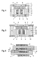
- the structural design of the two components 1 and 2 varies. Some embodiments of the components 1 and 2 are shown in FIGS. 6 to 9. The type of representation was selected analogously to FIG. 1. Other elements of the linear motor, such as the struts 9 or the leaf springs 13 are not shown in these figures for the sake of clarity. To form the linear motor these and possibly other elements are to be completed in each case. Since in the following embodiments, the coil 4 and the permanent magnets 6 are arranged in part on the same component, this component would be referred to both as iron core 3 and as a support plate 7. In order to ensure an unambiguous assignment, the component is referred to as iron core 3, if it has a coil 4 and possibly additional permanent magnets 6. Are only permanent magnets 6 present, the component is referred to as a support plate 7.
- Fig. 6 shows an embodiment in which the first and second components 1 and 2 are identical.
- the two components 1 and 2 each have an elongate iron core 3, at one end of which a shoulder 19 is formed. Following the shoulder 19, the coil 4 is wound on the iron core 3. In the region of its second end, the permanent magnets 6 are glued next to the coil 4 on the iron core 3.
- the components 1 and 2 formed in this way oppose each other in antiparallel, ie the shoulder 19 of the first component 1 is adjacent to the permanent magnet 6 of the second component 2 and the permanent magnets 6 of the first component 1 are adjacent to the shoulder 19 of the second component 2.
- This embodiment is thus characterized from that the mutually oscillating components 1 and 2 have exactly the same mass and are arranged very close to each other. Due to the identical design of the two components 1 and 2 simplifies the manufacturing process and the number of parts to be produced is reduced.
- Fig. 7 shows a further embodiment in which the first and second components 1 and 2 are identical.
- This exemplary embodiment is subordinated to FIG. 6 in that a free space still exists between the coil 4 and the adjacent shoulder 19 or the adjacent permanent magnet 6 and the coil 4 is not fixed on the iron core 3 in each case.
- the coils 4 are thus not mechanically connected to the other components of the components 1 and 2 and do not move with these, but are stationary. As a result, on the one hand reduce the moving masses and consequently the vibration caused thereby. On the other hand, the contacting of the coil 4 is simplified because they do not move and thus are not to make such high demands on the contact training.
- the iron cores 3 are formed in accordance with FIG. 6 and execute a corresponding oscillation movement.
- Fig. 8 shows a further embodiment with fixed coils 4.
- This embodiment has a U-shaped and a rod-shaped iron core 3.
- Each iron core 3 has a coil 4, which surrounds the iron core 3 at a small distance, so that the iron core 3 can be displaced relative to the coil 4 in each case.
- the permanent magnets 6 are also glued in the region of its ends. The iron cores 3 are positioned relative to each other such that the legs of the U-shaped iron core 3 are adjacent to the permanent magnet 6 of the rod-shaped iron core 3.
- FIG. 9 shows a modification of the embodiment of FIG. 8.
- This embodiment is distinguished from FIG. 8 in that only one coil 4 is present.
- This coil 4 surrounds the U-shaped iron core 3 at a small distance, in turn, a shift of the U-shaped iron core 3 relative to the coil 4 is possible, so that the U-shaped iron core 3 can perform a vibrating motion with fixed coil 4.
- the legs of the U-shaped iron core 3 are adjacent to the glued on the support plate 7 permanent magnets. 6
- the drive device according to the invention can also be designed as an oscillating rotary motor.
- a corresponding embodiment is shown in FIGS. 10 and 11.
- FIG. 10 and 11 show an embodiment of an oscillating rotary motor according to the invention in different states of motion in a representation corresponding to FIG.
- the first and second components 1 and 2 of the rotary motor are respectively in an equilibrium position
- the first and second components 1 and 2 are respectively deflected.
- the iron core 3 is rod-shaped, so that when energizing the wound around the iron core coil 4 at the end faces of the iron core 3 magnetic poles are formed.
- at least one permanent magnet 6 is arranged in each case such that in each case a magnetic north pole and a magnetic south pole are adjacent to one another at the same distance from the end face of the iron core 3.
- the support plate 7, on which the permanent magnets 6 are arranged, is annular and encloses the iron core 3 together with coil 4. This allows unwanted magnetic stray fields are kept relatively low.
- a central axis 20 for rotatably supporting both the first component 1 and the second component 2 is arranged, i. H. the only degree of freedom of movement for both the first component 1 and the second component 2 is a rotation about this central axis 20.
- a coil spring 21 is attached on two opposite sides in the two end regions of the iron core 3. The coil springs 21 extend from their points of attack on the iron core 3 to the support plate 7. If otherwise no forces acting the first component 1 is held by the coil springs 21 in the equilibrium position shown in Fig. 10.
- a rotary beam 22 is pivotally connected at one end thereof.
- the other end of the pivot bar 22 is rotatably hinged to the support plate 7.
- a centrally located central axis 23 of the rotary beam 22 is suspended rotatably.
- the connection to the device can also be made via the central axis 20.
- the current flow in the coil 4 is changed so that the conditions reverse and the permanent magnets 6 and the ends of the iron core 3 are deflected to the other side.
- oscillating rotational movements of the first component 1 and the second component 2 can be generated, which run in opposite directions to each other.
- the oscillating rotational movement is assisted by the coil springs 21, in particular when the coil 4 is driven so that the first and second components 1 and 2 oscillate at the resonant frequency.
- the exact maintenance of the phase relationship is ensured by the rotating beam 22, which enforces an antiphase of the two components 1 and 2 by its shown in FIGS. 10 and 11 articulation and storage. Strict adherence to the phase relationship can also be achieved through other measures.
- a toothed wheel may be provided which engages in a toothing in the first component 1 and in a toothing in the second component 2.
Landscapes
- Engineering & Computer Science (AREA)
- Life Sciences & Earth Sciences (AREA)
- Forests & Forestry (AREA)
- Mechanical Engineering (AREA)
- Power Engineering (AREA)
- Reciprocating, Oscillating Or Vibrating Motors (AREA)
- Lock And Its Accessories (AREA)
- Dry Shavers And Clippers (AREA)
- Fittings On The Vehicle Exterior For Carrying Loads, And Devices For Holding Or Mounting Articles (AREA)
- Control Of Electric Motors In General (AREA)
Applications Claiming Priority (3)
| Application Number | Priority Date | Filing Date | Title |
|---|---|---|---|
| DE10225024A DE10225024A1 (de) | 2002-06-06 | 2002-06-06 | Antriebseinrichtung zur Erzeugung einer oszillierenden Bewegung für ein elektrisches Kleingerät |
| DE10225024 | 2002-06-06 | ||
| PCT/EP2002/012929 WO2003103905A1 (de) | 2002-06-06 | 2002-11-19 | Antriebseinrichtung zur erzeugung einer oszillierenden bewegung für ein elektrisches kleingerät |
Publications (2)
| Publication Number | Publication Date |
|---|---|
| EP1509368A1 EP1509368A1 (de) | 2005-03-02 |
| EP1509368B1 true EP1509368B1 (de) | 2008-01-09 |
Family
ID=29594289
Family Applications (1)
| Application Number | Title | Priority Date | Filing Date |
|---|---|---|---|
| EP02807502A Expired - Lifetime EP1509368B1 (de) | 2002-06-06 | 2002-11-19 | Antriebseinrichtung zur erzeugung einer oszillierenden bewegung für ein elektrisches kleingerät |
Country Status (7)
| Country | Link |
|---|---|
| EP (1) | EP1509368B1 (ja) |
| JP (1) | JP4286778B2 (ja) |
| CN (1) | CN1309537C (ja) |
| AT (1) | ATE383231T1 (ja) |
| AU (1) | AU2002368009A1 (ja) |
| DE (2) | DE10225024A1 (ja) |
| WO (1) | WO2003103905A1 (ja) |
Families Citing this family (28)
| Publication number | Priority date | Publication date | Assignee | Title |
|---|---|---|---|---|
| US7355305B2 (en) * | 2003-12-08 | 2008-04-08 | Shen-Etsu Chemical Co., Ltd. | Small-size direct-acting actuator |
| DE102004010847A1 (de) * | 2004-03-05 | 2005-09-22 | BSH Bosch und Siemens Hausgeräte GmbH | Lineare Antriebseinrichtung mit Magnetjochkörper und permanentmagnetischem Ankerkörper |
| EP1610447B1 (en) * | 2004-06-14 | 2009-09-09 | Matsushita Electric Works, Ltd. | Driving unit |
| DE102006034050A1 (de) * | 2006-07-20 | 2008-01-24 | Braun Gmbh | Elektrischer Rasierapparat |
| KR20100016600A (ko) * | 2007-04-18 | 2010-02-12 | 코닌클리케 필립스 일렉트로닉스 엔.브이. | 전기-기계적 마사지 디바이스 및 착용 가능한 마사지 장치 |
| EP2136762A1 (en) * | 2007-04-18 | 2009-12-30 | Koninklijke Philips Electronics N.V. | Electro-mechanical massage device and wearable massage apparatus |
| JP2009240046A (ja) * | 2008-03-26 | 2009-10-15 | Panasonic Electric Works Co Ltd | 電磁アクチュエータ |
| DE102008031134B4 (de) | 2008-07-01 | 2010-10-07 | Braun Gmbh | Oszillierender Rotationsmotor sowie elektrisch betriebenes Kleingerät hierzu |
| US8282268B2 (en) * | 2009-02-24 | 2012-10-09 | Island Oasis Frozen Cocktail Co., Inc. | Magnetic drive for food processing apparatus |
| KR101156787B1 (ko) * | 2009-07-27 | 2012-06-18 | 삼성전기주식회사 | 선형 진동자 |
| JP2011067419A (ja) * | 2009-09-25 | 2011-04-07 | Panasonic Electric Works Co Ltd | 電気かみそり |
| JP4875133B2 (ja) * | 2009-10-29 | 2012-02-15 | 日本電産コパル株式会社 | 振動アクチュエータ |
| CN102665600B (zh) * | 2009-12-23 | 2015-09-09 | 皇家飞利浦电子股份有限公司 | 刷头内具有促动器的电动牙刷 |
| GB2485201A (en) * | 2010-11-05 | 2012-05-09 | Mafaq Abdul Razak | Apparatus for generating an oscillating magnetic field |
| FR2971902B1 (fr) * | 2011-02-23 | 2013-11-08 | Moving Magnet Tech | Actionneur electromagnetique a densite de force amelioree et application a un rasoir electrique |
| JP5963052B2 (ja) * | 2012-12-27 | 2016-08-03 | パナソニックIpマネジメント株式会社 | 電動リニアアクチュエーターおよびこの電動リニアアクチュエーターを有する出力軸振動型電動装置 |
| JP2014128188A (ja) * | 2012-12-27 | 2014-07-07 | Panasonic Corp | 電動リニアアクチュエーターおよびこの電動リニアアクチュエーターを有する出力軸振動型電動装置 |
| JP6296594B2 (ja) * | 2013-09-04 | 2018-03-20 | 日本電産セイミツ株式会社 | 振動発生装置 |
| JP6405046B2 (ja) * | 2014-12-23 | 2018-10-17 | ブラウン ゲーエムベーハー | リニアモータ及びその支持体 |
| CN204886638U (zh) * | 2015-07-31 | 2015-12-16 | 瑞声光电科技(常州)有限公司 | 微型振动电机 |
| EP3300861B1 (en) | 2016-09-28 | 2019-07-03 | Braun GmbH | Electrically driven device |
| JP6765079B2 (ja) * | 2017-04-19 | 2020-10-07 | パナソニックIpマネジメント株式会社 | 振動型リニアアクチュエータ、および、体毛処理機 |
| EP3396827B1 (en) | 2017-04-27 | 2023-06-28 | Braun GmbH | Electric appliance for personal care |
| EP3396828B1 (en) | 2017-04-27 | 2021-08-18 | Braun GmbH | Electric appliance for personal care |
| EP3396826B1 (en) | 2017-04-27 | 2022-10-19 | Braun GmbH | Electric appliance for personal care |
| EP3396821B1 (en) | 2017-04-27 | 2023-06-14 | Braun GmbH | Electric shaver |
| ES2906953T3 (es) | 2019-05-02 | 2022-04-21 | Braun Gmbh | Dispositivo de higiene personal |
| JP2023023948A (ja) * | 2021-08-06 | 2023-02-16 | ミネベアミツミ株式会社 | 振動アクチュエーター |
Citations (2)
| Publication number | Priority date | Publication date | Assignee | Title |
|---|---|---|---|---|
| DE1463988A1 (de) * | 1963-02-02 | 1969-07-10 | Richards Morphy N I Ltd | Vibrationsmotor |
| US3505545A (en) * | 1967-05-26 | 1970-04-07 | Ahmet K Bey | Polarized vibratory motor |
Family Cites Families (11)
| Publication number | Priority date | Publication date | Assignee | Title |
|---|---|---|---|---|
| CH265598A (de) * | 1946-01-23 | 1949-12-15 | Odstrcil Borivoj | Trockenrasierapparat. |
| US2741711A (en) * | 1951-02-16 | 1956-04-10 | Schick Inc | Electric shaver vibrator motor |
| NL264048A (ja) * | 1960-09-29 | |||
| FR2179653B1 (ja) * | 1972-04-13 | 1974-07-26 | Crouzet Sa | |
| AT353141B (de) * | 1978-02-10 | 1979-10-25 | Philips Nv | Trockenrasierapparat |
| JPS6266882A (ja) * | 1985-09-20 | 1987-03-26 | 松下電工株式会社 | 往復駆動装置の防振装置 |
| JP3266757B2 (ja) * | 1995-05-26 | 2002-03-18 | 松下電工株式会社 | 振動型リニアアクチュエータ |
| DE19781664C2 (de) * | 1996-03-26 | 2001-08-23 | Matsushita Electric Works Ltd | Elektrischer Rasierer |
| DE19736776C2 (de) * | 1997-08-23 | 1999-06-02 | Braun Gmbh | Trockenrasierapparat |
| JP2000316267A (ja) * | 1999-04-27 | 2000-11-14 | Matsushita Electric Works Ltd | 振動型リニアアクチュエータ |
| EP1162721B1 (en) * | 2000-06-07 | 2005-12-21 | Matsushita Electric Works, Ltd. | Linear oscillating actuator |
-
2002
- 2002-06-06 DE DE10225024A patent/DE10225024A1/de not_active Withdrawn
- 2002-11-19 CN CNB028290941A patent/CN1309537C/zh not_active Expired - Fee Related
- 2002-11-19 JP JP2004511011A patent/JP4286778B2/ja not_active Expired - Lifetime
- 2002-11-19 AT AT02807502T patent/ATE383231T1/de active
- 2002-11-19 DE DE50211537T patent/DE50211537D1/de not_active Expired - Lifetime
- 2002-11-19 AU AU2002368009A patent/AU2002368009A1/en not_active Abandoned
- 2002-11-19 WO PCT/EP2002/012929 patent/WO2003103905A1/de active IP Right Grant
- 2002-11-19 EP EP02807502A patent/EP1509368B1/de not_active Expired - Lifetime
Patent Citations (2)
| Publication number | Priority date | Publication date | Assignee | Title |
|---|---|---|---|---|
| DE1463988A1 (de) * | 1963-02-02 | 1969-07-10 | Richards Morphy N I Ltd | Vibrationsmotor |
| US3505545A (en) * | 1967-05-26 | 1970-04-07 | Ahmet K Bey | Polarized vibratory motor |
Also Published As
| Publication number | Publication date |
|---|---|
| WO2003103905A1 (de) | 2003-12-18 |
| ATE383231T1 (de) | 2008-01-15 |
| EP1509368A1 (de) | 2005-03-02 |
| DE50211537D1 (de) | 2008-02-21 |
| CN1628013A (zh) | 2005-06-15 |
| JP2005532771A (ja) | 2005-10-27 |
| CN1309537C (zh) | 2007-04-11 |
| AU2002368009A1 (en) | 2003-12-22 |
| JP4286778B2 (ja) | 2009-07-01 |
| DE10225024A1 (de) | 2003-12-24 |
Similar Documents
| Publication | Publication Date | Title |
|---|---|---|
| EP1509368B1 (de) | Antriebseinrichtung zur erzeugung einer oszillierenden bewegung für ein elektrisches kleingerät | |
| EP1641602B1 (de) | Elektrisches kleingerät mit einem elektromotor zur erzeugung einer oszillierenden bewegung | |
| EP1539437B1 (de) | Elektrisches kleingerät mit einer antriebseinrichtung zur erzeugung einer oszillierenden bewegung | |
| EP2108215B1 (de) | Antriebsvorrichtung zum antreiben eines bürstenelements einer elektrischen zahnbürste | |
| EP2043828B1 (de) | Elektrischer rasierapparat | |
| EP1687887B1 (de) | Elektromotor für ein elektrisches kleingerät | |
| US6933630B2 (en) | Drive mechanisms for small electric appliances | |
| DE102005060537A1 (de) | Elektrischer Rasierapparat mit oszillierendem Scherkopf | |
| WO2000013297A1 (de) | Elektromagnetischer aktuator mit schwingendem feder-masse-system | |
| EP1678813B1 (de) | Antriebseinheit zur erzeugung einer oszillierenden bewegung für elektrische kleingeräte | |
| DE10242094B4 (de) | Antriebseinrichtung zum Erzeugen einer oszillierenden Bewegung für ein elektrisches Kleingerät | |
| EP1539439B1 (de) | Elektrisches kleingerät mit einer antriebseinrichtung zur erzeugung einer oszillierenden bewegung | |
| WO2005120781A1 (de) | Elektrischer rasierapparat mit einem schwenkbaren scherkopf | |
| EP1539438B1 (de) | Antriebseinrichtung zum erzeugen einer oszillierenden bewegung für ein elektrisches kleingerät | |
| DE102008031134B4 (de) | Oszillierender Rotationsmotor sowie elektrisch betriebenes Kleingerät hierzu | |
| EP1642380B1 (de) | Verfahren zur steuerung eines elektromotors mit mehreren schwingungsfähigen motorkomponenten | |
| EP0119410A1 (de) | Schwingförderer mit Rüttelförderschale | |
| DE843570C (de) | Elektromagnetischer Schwingungserzeuger | |
| DE947350C (de) | Anordnung zur Herstellung von Schweissverbindungen | |
| DE479335C (de) | Schwingende bzw. oszillierende, elektrische Maschine mit konstantem Luftspalt zur Leistungsuebertragung | |
| DE4117226A1 (de) | Haushaltsvibrationsgeraet mit einem vibrationsteil und einstellbarer eigenfrequenz |
Legal Events
| Date | Code | Title | Description |
|---|---|---|---|
| PUAI | Public reference made under article 153(3) epc to a published international application that has entered the european phase |
Free format text: ORIGINAL CODE: 0009012 |
|
| 17P | Request for examination filed |
Effective date: 20041028 |
|
| AK | Designated contracting states |
Kind code of ref document: A1 Designated state(s): AT BE BG CH CY CZ DE DK EE ES FI FR GB GR IE IT LI LU MC NL PT SE SK TR |
|
| AX | Request for extension of the european patent |
Extension state: AL LT LV MK RO SI |
|
| 17Q | First examination report despatched |
Effective date: 20050304 |
|
| DAX | Request for extension of the european patent (deleted) | ||
| GRAP | Despatch of communication of intention to grant a patent |
Free format text: ORIGINAL CODE: EPIDOSNIGR1 |
|
| GRAS | Grant fee paid |
Free format text: ORIGINAL CODE: EPIDOSNIGR3 |
|
| GRAA | (expected) grant |
Free format text: ORIGINAL CODE: 0009210 |
|
| AK | Designated contracting states |
Kind code of ref document: B1 Designated state(s): AT BE BG CH CY CZ DE DK EE ES FI FR GB GR IE IT LI LU MC NL PT SE SK TR |
|
| REG | Reference to a national code |
Ref country code: GB Ref legal event code: FG4D Free format text: NOT ENGLISH |
|
| REG | Reference to a national code |
Ref country code: CH Ref legal event code: EP Ref country code: CH Ref legal event code: NV Representative=s name: LUCHS & PARTNER PATENTANWAELTE |
|
| REG | Reference to a national code |
Ref country code: IE Ref legal event code: FG4D Free format text: LANGUAGE OF EP DOCUMENT: GERMAN |
|
| REF | Corresponds to: |
Ref document number: 50211537 Country of ref document: DE Date of ref document: 20080221 Kind code of ref document: P |
|
| GBT | Gb: translation of ep patent filed (gb section 77(6)(a)/1977) |
Effective date: 20080411 |
|
| PG25 | Lapsed in a contracting state [announced via postgrant information from national office to epo] |
Ref country code: FI Free format text: LAPSE BECAUSE OF FAILURE TO SUBMIT A TRANSLATION OF THE DESCRIPTION OR TO PAY THE FEE WITHIN THE PRESCRIBED TIME-LIMIT Effective date: 20080109 Ref country code: ES Free format text: LAPSE BECAUSE OF FAILURE TO SUBMIT A TRANSLATION OF THE DESCRIPTION OR TO PAY THE FEE WITHIN THE PRESCRIBED TIME-LIMIT Effective date: 20080420 |
|
| ET | Fr: translation filed | ||
| PG25 | Lapsed in a contracting state [announced via postgrant information from national office to epo] |
Ref country code: BG Free format text: LAPSE BECAUSE OF FAILURE TO SUBMIT A TRANSLATION OF THE DESCRIPTION OR TO PAY THE FEE WITHIN THE PRESCRIBED TIME-LIMIT Effective date: 20080409 |
|
| PG25 | Lapsed in a contracting state [announced via postgrant information from national office to epo] |
Ref country code: PT Free format text: LAPSE BECAUSE OF FAILURE TO SUBMIT A TRANSLATION OF THE DESCRIPTION OR TO PAY THE FEE WITHIN THE PRESCRIBED TIME-LIMIT Effective date: 20080609 |
|
| REG | Reference to a national code |
Ref country code: IE Ref legal event code: FD4D |
|
| PG25 | Lapsed in a contracting state [announced via postgrant information from national office to epo] |
Ref country code: DK Free format text: LAPSE BECAUSE OF FAILURE TO SUBMIT A TRANSLATION OF THE DESCRIPTION OR TO PAY THE FEE WITHIN THE PRESCRIBED TIME-LIMIT Effective date: 20080109 Ref country code: IE Free format text: LAPSE BECAUSE OF FAILURE TO SUBMIT A TRANSLATION OF THE DESCRIPTION OR TO PAY THE FEE WITHIN THE PRESCRIBED TIME-LIMIT Effective date: 20080109 Ref country code: SK Free format text: LAPSE BECAUSE OF FAILURE TO SUBMIT A TRANSLATION OF THE DESCRIPTION OR TO PAY THE FEE WITHIN THE PRESCRIBED TIME-LIMIT Effective date: 20080109 Ref country code: CZ Free format text: LAPSE BECAUSE OF FAILURE TO SUBMIT A TRANSLATION OF THE DESCRIPTION OR TO PAY THE FEE WITHIN THE PRESCRIBED TIME-LIMIT Effective date: 20080109 Ref country code: SE Free format text: LAPSE BECAUSE OF FAILURE TO SUBMIT A TRANSLATION OF THE DESCRIPTION OR TO PAY THE FEE WITHIN THE PRESCRIBED TIME-LIMIT Effective date: 20080409 |
|
| PLBE | No opposition filed within time limit |
Free format text: ORIGINAL CODE: 0009261 |
|
| STAA | Information on the status of an ep patent application or granted ep patent |
Free format text: STATUS: NO OPPOSITION FILED WITHIN TIME LIMIT |
|
| 26N | No opposition filed |
Effective date: 20081010 |
|
| PG25 | Lapsed in a contracting state [announced via postgrant information from national office to epo] |
Ref country code: EE Free format text: LAPSE BECAUSE OF FAILURE TO SUBMIT A TRANSLATION OF THE DESCRIPTION OR TO PAY THE FEE WITHIN THE PRESCRIBED TIME-LIMIT Effective date: 20080109 |
|
| PG25 | Lapsed in a contracting state [announced via postgrant information from national office to epo] |
Ref country code: MC Free format text: LAPSE BECAUSE OF NON-PAYMENT OF DUE FEES Effective date: 20081130 |
|
| PG25 | Lapsed in a contracting state [announced via postgrant information from national office to epo] |
Ref country code: CY Free format text: LAPSE BECAUSE OF FAILURE TO SUBMIT A TRANSLATION OF THE DESCRIPTION OR TO PAY THE FEE WITHIN THE PRESCRIBED TIME-LIMIT Effective date: 20080109 |
|
| PG25 | Lapsed in a contracting state [announced via postgrant information from national office to epo] |
Ref country code: IT Free format text: LAPSE BECAUSE OF FAILURE TO SUBMIT A TRANSLATION OF THE DESCRIPTION OR TO PAY THE FEE WITHIN THE PRESCRIBED TIME-LIMIT Effective date: 20080109 |
|
| PG25 | Lapsed in a contracting state [announced via postgrant information from national office to epo] |
Ref country code: LU Free format text: LAPSE BECAUSE OF NON-PAYMENT OF DUE FEES Effective date: 20081119 |
|
| PG25 | Lapsed in a contracting state [announced via postgrant information from national office to epo] |
Ref country code: TR Free format text: LAPSE BECAUSE OF FAILURE TO SUBMIT A TRANSLATION OF THE DESCRIPTION OR TO PAY THE FEE WITHIN THE PRESCRIBED TIME-LIMIT Effective date: 20080109 |
|
| PG25 | Lapsed in a contracting state [announced via postgrant information from national office to epo] |
Ref country code: GR Free format text: LAPSE BECAUSE OF FAILURE TO SUBMIT A TRANSLATION OF THE DESCRIPTION OR TO PAY THE FEE WITHIN THE PRESCRIBED TIME-LIMIT Effective date: 20080410 |
|
| PGFP | Annual fee paid to national office [announced via postgrant information from national office to epo] |
Ref country code: AT Payment date: 20101022 Year of fee payment: 9 Ref country code: NL Payment date: 20101025 Year of fee payment: 9 |
|
| PGFP | Annual fee paid to national office [announced via postgrant information from national office to epo] |
Ref country code: BE Payment date: 20101116 Year of fee payment: 9 Ref country code: GB Payment date: 20101022 Year of fee payment: 9 |
|
| PGFP | Annual fee paid to national office [announced via postgrant information from national office to epo] |
Ref country code: FR Payment date: 20111103 Year of fee payment: 10 Ref country code: CH Payment date: 20111026 Year of fee payment: 10 |
|
| BERE | Be: lapsed |
Owner name: BRAUN G.M.B.H. Effective date: 20111130 |
|
| REG | Reference to a national code |
Ref country code: NL Ref legal event code: V1 Effective date: 20120601 |
|
| PG25 | Lapsed in a contracting state [announced via postgrant information from national office to epo] |
Ref country code: NL Free format text: LAPSE BECAUSE OF NON-PAYMENT OF DUE FEES Effective date: 20120601 |
|
| PG25 | Lapsed in a contracting state [announced via postgrant information from national office to epo] |
Ref country code: BE Free format text: LAPSE BECAUSE OF NON-PAYMENT OF DUE FEES Effective date: 20111130 |
|
| REG | Reference to a national code |
Ref country code: AT Ref legal event code: MM01 Ref document number: 383231 Country of ref document: AT Kind code of ref document: T Effective date: 20111119 |
|
| PG25 | Lapsed in a contracting state [announced via postgrant information from national office to epo] |
Ref country code: AT Free format text: LAPSE BECAUSE OF NON-PAYMENT OF DUE FEES Effective date: 20111119 |
|
| REG | Reference to a national code |
Ref country code: CH Ref legal event code: PL |
|
| GBPC | Gb: european patent ceased through non-payment of renewal fee |
Effective date: 20121119 |
|
| PG25 | Lapsed in a contracting state [announced via postgrant information from national office to epo] |
Ref country code: CH Free format text: LAPSE BECAUSE OF NON-PAYMENT OF DUE FEES Effective date: 20121130 Ref country code: LI Free format text: LAPSE BECAUSE OF NON-PAYMENT OF DUE FEES Effective date: 20121130 |
|
| REG | Reference to a national code |
Ref country code: FR Ref legal event code: ST Effective date: 20130731 |
|
| PG25 | Lapsed in a contracting state [announced via postgrant information from national office to epo] |
Ref country code: GB Free format text: LAPSE BECAUSE OF NON-PAYMENT OF DUE FEES Effective date: 20121119 Ref country code: FR Free format text: LAPSE BECAUSE OF NON-PAYMENT OF DUE FEES Effective date: 20121130 |
|
| PGFP | Annual fee paid to national office [announced via postgrant information from national office to epo] |
Ref country code: DE Payment date: 20211005 Year of fee payment: 20 |
|
| REG | Reference to a national code |
Ref country code: DE Ref legal event code: R071 Ref document number: 50211537 Country of ref document: DE |