EP1509368B1 - Drive device for generating an oscillating motion for a small electric appliance - Google Patents
Drive device for generating an oscillating motion for a small electric appliance Download PDFInfo
- Publication number
- EP1509368B1 EP1509368B1 EP02807502A EP02807502A EP1509368B1 EP 1509368 B1 EP1509368 B1 EP 1509368B1 EP 02807502 A EP02807502 A EP 02807502A EP 02807502 A EP02807502 A EP 02807502A EP 1509368 B1 EP1509368 B1 EP 1509368B1
- Authority
- EP
- European Patent Office
- Prior art keywords
- drive
- drive mechanism
- component
- drive component
- components
- Prior art date
- Legal status (The legal status is an assumption and is not a legal conclusion. Google has not performed a legal analysis and makes no representation as to the accuracy of the status listed.)
- Expired - Lifetime
Links
Images


Classifications
-
- B—PERFORMING OPERATIONS; TRANSPORTING
- B26—HAND CUTTING TOOLS; CUTTING; SEVERING
- B26B—HAND-HELD CUTTING TOOLS NOT OTHERWISE PROVIDED FOR
- B26B19/00—Clippers or shavers operating with a plurality of cutting edges, e.g. hair clippers, dry shavers
- B26B19/28—Drive layout for hair clippers or dry shavers, e.g. providing for electromotive drive
- B26B19/288—Balance by opposing oscillation
-
- B—PERFORMING OPERATIONS; TRANSPORTING
- B26—HAND CUTTING TOOLS; CUTTING; SEVERING
- B26B—HAND-HELD CUTTING TOOLS NOT OTHERWISE PROVIDED FOR
- B26B19/00—Clippers or shavers operating with a plurality of cutting edges, e.g. hair clippers, dry shavers
- B26B19/28—Drive layout for hair clippers or dry shavers, e.g. providing for electromotive drive
- B26B19/282—Motors without a rotating central drive shaft, e.g. linear motors
-
- H—ELECTRICITY
- H02—GENERATION; CONVERSION OR DISTRIBUTION OF ELECTRIC POWER
- H02K—DYNAMO-ELECTRIC MACHINES
- H02K33/00—Motors with reciprocating, oscillating or vibrating magnet, armature or coil system
- H02K33/02—Motors with reciprocating, oscillating or vibrating magnet, armature or coil system with armatures moved one way by energisation of a single coil system and returned by mechanical force, e.g. by springs
- H02K33/04—Motors with reciprocating, oscillating or vibrating magnet, armature or coil system with armatures moved one way by energisation of a single coil system and returned by mechanical force, e.g. by springs wherein the frequency of operation is determined by the frequency of uninterrupted AC energisation
Definitions
- the invention relates to a drive device for generating an oscillating movement for a small electrical appliance according to the preamble of claim 1.
- a drive device which discloses a Schwingankerantrieb for dry shavers with reciprocating working movement of a doctor blade having a fixedly connected to the housing of the shaver and U-shaped electromagnet.
- a working anchor and on each side of the working anchor each a compensating anchor are arranged to vibrate.
- the working anchor which drives a razor, oscillates parallel to the pole faces of the electromagnet, with the counterpoise anchors performing antiphase oscillatory motion to minimize transmission of the working anchor vibration to the shaver housing.
- Another drive device is from the DE-A-1 463 988 which also discloses a coil for forming a magnetic field emanating from a first drive component and acting on a second drive component which is movably arranged in the small electrical appliance so that the second drive component is placed in an oscillating motion.
- the first drive component is mounted on a worktop, which is mounted so that it can oscillate in phase opposition to the second drive component.
- the DE 196 80 506 T1 discloses an oscillating linear motor with a stationary electromagnet and a plurality of movable components, which are offset by means of the electromagnet in opposite antiphase oscillatory movements. In order to maintain the phase relationship of the movable components to each other even under load, they are interconnected by means of a link mechanism, which transmits the oscillatory motion, reversing the direction from one to the other movable component.
- An electric razor with a linear drive which has a hollow cylindrical stator with an electromagnetic coil.
- the stator two movable elements are arranged, which are driven in opposite phase to each other one of which drives a shearing blade and the other may have a counterweight to suppress unwanted vibrations.
- the invention has for its object to provide a drive device for generating an oscillating movement for a small electrical appliance with improved properties.
- the first drive component is arranged for performing a movement to the second drive component in opposite phase oscillating movement in the small electrical appliance.
- At least one of the two drive components may comprise one or more permanent magnets. Furthermore, at least one of the two drive components may have a winding core on which the coil is arranged. This can be implemented at relatively small dimensions, a powerful drive, the power consumption is sufficiently low, for example, to allow battery operation of the small electrical appliance.
- At least one elastic element can be provided for generating restoring forces.
- a vibratory system is formed, which is preferably operated under resonance conditions.
- the coupling element is respectively rotatably articulated to the first drive component and to the second drive component.
- the antiphase can be produced in a particularly simple manner in that the coupling element is rotatably mounted.
- the coupling element is rotatably mounted on a fastening axis for fastening the drive device to the small electrical appliance. This is advisable because the pivot point of the coupling element does not move and thus attachment to the small device is easily possible.
- the attachment axis can be centered between the articulation of the coupling element to be arranged on the first drive component and on the second drive component. This has the advantage that the concomitant amplitude equality of the vibration movements of the two drive components is maintained even under different load of the drive components.
- the coupling element may have at least one additional drive tap for tapping a vibrational motion having a different amplitude than the vibrations of the first and second drive components. This has the advantage that no gear is needed for the provision of the additional oscillatory motion and thus reduces the effort and reliability is increased.
- the drive device is designed as a linear motor, in which the two drive components are displaceable relative to one another, so that a linearly oscillating movement is produced.
- the elastic element is designed as a leaf spring, which is attached to the first drive component and to the second drive component.
- the leaf spring thus counteracts a deflection of the two drive components relative to each other and has the advantage that it requires extremely little space.
- the leaf spring can be attached to at least one of the drive components with play transversely to the direction of movement of the drive components, so that the length reduction of the leaf spring associated with the bending is made possible.
- the coupling element is articulated in each case at least one of the drive components with play transversely to the direction of movement of the drive components.
- the coupling element may be rotatably articulated to the deflection lever, which are each connected to the drive component further from the articulation point.
- the two drive components it is possible to form the two drive components identical, so that the production cost can be kept very low. Furthermore, there is the possibility that the winding core is arranged displaceable relative to the coil. Since, in such an embodiment, the coil does not move with the winding core, the movable masses can be kept low, so that less vibrations are caused on the electrical appliance. In addition, the contact of the coil is simplified because it does not move.
- the first drive component and the second drive component can be guided by means of linear bearings. In this way it is possible to produce a particularly precise linear movement. A similar effect can also be achieved by keeping the first drive component and the second drive component at a constant distance from one another by means of at least one spacer element.
- the spacer is preferably rotatably mounted about the mounting axis and is supported in particular on curved surfaces on bearing surfaces of the first and the second drive component.
- the curved surfaces may be formed as cylinder segments and associated with the cylinder segments cylinder axes may each coincide with the mounting axis.
- the drive device is designed as a rotary motor, in which the two drive components are rotatable relative to each other.
- the two drive components preferably have a common axis of rotation.
- the coupling element can be designed, for example, as a toothed wheel which engages in a toothing in the first drive component and in a toothing in the second drive component.
- the drive device can be designed as an oscillating linear motor or as an oscillating rotary motor.
- the oscillating linear motor produces linear movements of small amplitude, which can be used, for example, in electric shavers.
- the oscillating rotary motor generates small rotational movements whose direction of rotation reverses periodically and is suitable, for example, for use with electric toothbrushes.
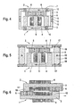
- Fig. 1 shows an embodiment of an oscillating linear motor in a highly schematic representation.
- the linear motor has two movable components 1 and 2, which are arranged at a small distance from each other.
- the first component 1 consists of an iron core 3, which is formed in the shape of an "E", and a coil 4 wound from wire.
- the coil 4 is wound around a center beam 5 of the iron core 3.
- the second component 2 has two permanent magnets 6, which are arranged side by side with antiparallel oriented polarity on a common carrier plate 7.
- the support plate 7, like the iron core 3, consists of a ferrous material.
- the permanent magnets 6 are approximated to an air gap 8 of the end face of the central bar 5 of the iron core 3.
- the support plate 7, on which the permanent magnets 6 are arranged, is supported on the iron core 3 via two struts 9.
- the two struts 9 are each mounted in the region of their ends by means of connecting shafts 10 rotatably mounted in bearing blocks 11 which are fixed to the iron core 3 and to the support plate 7.
- Center between the connecting axes 10, the two struts 9 each have a mounting axis 12, which serves to attach the linear motor to its installation environment, for example to the housing of an electric shaver.
- Leaf springs 13 extend in parallel with the struts 9 between the bearing blocks 11 fastened to the iron core 3 and to the support plate 7.
- the first and the second component 1 and 2 each perform a vibrational movement, which runs in the representation of FIG. 1 in a substantially horizontal direction.
- the directions of movement of the two components 1 and 2 are in each case opposite each other, d h. the vibrations are in phase opposition to each other.
- the exact antiphase of the vibrations is enforced by the rotatable suspension of the struts 9 by means of the attachment axes 12. This suspension also has the consequence that the trajectories of the centers of gravity of the first and second components 1 and 2 are slightly curved. In the illustration of FIG.
- the trajectory of the center of gravity of the first component 1 is slightly downwards and the trajectory of the center of gravity of the second component 2 is curved slightly upward.
- the return to the equilibrium position is driven by the restoring forces generated by the leaf springs 13. In the equilibrium position, the leaf springs 13 are not bent and consequently no restoring forces are generated. Without the intervention of others Forces, the two components 1 and 2 would thus remain in the equilibrium position.
- the leaf springs 13 With increasing deflection of the two components 1 and 2 from the equilibrium position, the leaf springs 13 are bent increasingly S-shaped so that restoring forces in the direction of equilibrium position become effective.
- the S-shaped bend of the leaf springs 13 is accompanied by a reduction of their longitudinal dimensions. This can be considered constructively in that the leaf springs 13 are each attached to at least one bearing block 11 with a slight play in the longitudinal direction, ie transverse to the direction of movement of the components 1 and 2.
- the game can be realized for example via an elastic suspension or a suspension by engaging in slots, which may optionally have an elastic insert.
- a current flow through the coil 4 is produced.
- the coil 4 acts as an electromagnet and generated by the iron core 3 generates a magnetic field which acts on the permanent magnets 6 and has a relative movement between the coil 4 and the permanent magnet 6 result.
- the magnetic field thus generated can be reversed in each case, so that the first and the second component 1 and 2 are offset from each other in antiphase oscillations.
- an essential aspect of the invention is that both the first component 1 and the second component 2 moves, d. h., That the linear motor according to the invention has no stator, with the aid of a rotor is driven, but two mutually oscillating components 1 and 2, which drive each other.
- One of these components 1 or 2 corresponds to the rotor of a conventional linear motor.
- the other takes over the functions of the stator of a conventional linear motor, but in contrast to this is not static, but also moves.
- this also means that, under otherwise identical conditions, the first and second components 1 and 2 of the linear motor according to the invention move relative to one another at a relative speed which is twice the relative speed between a stator and a rotor of a conventional linear motor. As a result, a relatively high efficiency can be achieved with the linear motor according to the invention.
- the frequency of the oscillatory movement of the two components 1 and 2 is determined by the control of the coil 4 and in particular adjusted so that it corresponds to the resonant frequency of the vibration system, by the two components. 1 and 2 and the leaf springs 13 is formed. Under resonant conditions results in a very robust vibration behavior and it is only a comparatively low energy input required.
- Fig. 2 shows a further embodiment of the linear motor according to the invention in a Fig. 1 corresponding representation.
- This embodiment differs from FIG. 1 essentially in that each strut 9 is assigned two deflection levers 14.
- the reversing levers 14 each establish a rigid connection between one of the bearing blocks 11 and the iron core 3 or the carrier plate 7.
- the deflection lever 14 of the bearing blocks 11 do not extend to the adjacent iron core 3 and to the adjacent support plate 7, but to the respective opposite component, so that the lever 14 cross.
- the lever 14 are not directly to the bearing blocks 11, but clamp the leaf springs 13, which are also attached to the bearing blocks 11 in this way.
- FIG. 1 A deflected state is shown by way of example in FIG. In this snapshot, the first component 1 are deflected to the left and the second component 2 to the right from the equilibrium position.
- the embodiment according to FIGS. 2 and 3 in its construction and its operation corresponds to the embodiment shown in FIG. 1 and is used in applications in which the described deviant behavior in the variation of the width of the air gap 8 is desired ,
- FIGS. 1, 2 and 3 central arrangement of the mounting axis 12 between the connecting axles 10 and an eccentric arrangement can be selected when different sized vibration amplitudes of the first and second components 1 and 2 are desired.
- the lower blade when using the linear motor according to the invention in an electric shaver, the lower blade can be operated with a large and the shear foil with a small oscillation amplitude.
- the attachment axis 12 is arranged so that the product of the total mass of the first component 1 including firmly connected components and the effective for this mass relative to the mounting axis 12 lever arm the same Value assumes as the product of the total mass of the second component 2 including firmly connected components and the effective for this mass relative to the mounting axis 12 lever arm.
- FIG. 4 shows a further exemplary embodiment of an oscillating linear motor in a representation corresponding to FIG. 1.
- This embodiment differs from the exemplary embodiment according to FIG. 1 in that additional drive taps 15 are provided, which enable the drive of additional units by the linear motor according to the invention.
- the struts 9 in contrast to FIG. 1 are not rod-shaped, but U-shaped and hinged with their legs directly to the iron core 3 and to the support plate 7. On the representation of the leaf springs! 3 was omitted for reasons of clarity.
- Each strut 9 has two additional drive taps 15, which are each arranged on both sides of the attachment axis 12.
- an additional drive tap 15 is arranged on the side of the first component 1 on a strut 9 and thus moves in phase with the first component 1.
- the second additional drive tap 15 of the same strut 9 is respectively arranged and moved on the side of the second component 2 in phase with the second component 2 and in opposite phase to the first additional drive tap 15. Since the two additional drive taps 15 a strut 9 are arranged much closer to the mounting axis 12, as is the case for the two connecting axes 10 of the same strut 9, the at the additional drive taps 15 tapped movements each have a substantially lower amplitude than the movements of the first and second components 1 and 2.
- the illustrated in Fig. 4 embodiment of the linear motor according to the invention can be used for example in an electric shavers with two Schermesserblöcken.
- the linear motor is attached to the housing of the razor via the two attachment axes 12.
- a cutter block is coupled to the first and to the second component 1 and 2, so that the two cutter blades move in opposite phases.
- the head of the razor and thus the shaving foil is operated by coupling to an additional drive tap 15 with small amplitude.
- the shaver has two separate shaving foils, it is also possible to drive the two shaving foils in mutual phase by coupling to two small amplitude driving taps 15.
- the coupling takes place in such a way that the movement of the shear foils also takes place in opposite phase to the respective associated cutter block.
- FIG. 5 shows an exemplary embodiment of the linear motor according to the invention, with which particularly precise linear movements can be generated.
- the type of representation has been selected according to Fig. 1, wherein the leaf springs 13 have been omitted again for reasons of clarity.
- the coupling of the first and the second component 1 and 2 takes place by means of two spacer elements 16.
- the two spacer elements 16 are rotatably supported by means of the mounting shafts 12 for the linear motor.
- the spacer elements 16 At their end faces 17, which are supported on bearing surfaces 18 provided for this purpose of the first and the second component 1 and 2, the spacer elements 16 each have a curvature.
- the bearing surfaces 18 roll on the end faces 17 of the spacers 16 and rotate the spacers 16 about the mounting shafts 12. This causes on the one hand a mechanical coupling of the movements of the first and on the other hand, the curvature on each end face 17 is formed so that the distance between the opposite bearing surfaces 18 remains the same despite the oscillatory movements of the first and second components 1 and 2 at any time. In the illustrated geometry, this is achieved in each case by the formation of the end face 17 as a cylinder segment, wherein the cylinder axis coincides with the fastening axis 12. Since the permanent magnets 6 exert a strong attraction force on the iron core 3, a mechanical connection between the spacer elements 16 and the iron core 3 or the support plate 7 is not absolutely necessary.
- the support surfaces 18 and the end surfaces 17 may be formed as intermeshing teeth.
- the structural design of the two components 1 and 2 varies. Some embodiments of the components 1 and 2 are shown in FIGS. 6 to 9. The type of representation was selected analogously to FIG. 1. Other elements of the linear motor, such as the struts 9 or the leaf springs 13 are not shown in these figures for the sake of clarity. To form the linear motor these and possibly other elements are to be completed in each case. Since in the following embodiments, the coil 4 and the permanent magnets 6 are arranged in part on the same component, this component would be referred to both as iron core 3 and as a support plate 7. In order to ensure an unambiguous assignment, the component is referred to as iron core 3, if it has a coil 4 and possibly additional permanent magnets 6. Are only permanent magnets 6 present, the component is referred to as a support plate 7.
- Fig. 6 shows an embodiment in which the first and second components 1 and 2 are identical.
- the two components 1 and 2 each have an elongate iron core 3, at one end of which a shoulder 19 is formed. Following the shoulder 19, the coil 4 is wound on the iron core 3. In the region of its second end, the permanent magnets 6 are glued next to the coil 4 on the iron core 3.
- the components 1 and 2 formed in this way oppose each other in antiparallel, ie the shoulder 19 of the first component 1 is adjacent to the permanent magnet 6 of the second component 2 and the permanent magnets 6 of the first component 1 are adjacent to the shoulder 19 of the second component 2.
- This embodiment is thus characterized from that the mutually oscillating components 1 and 2 have exactly the same mass and are arranged very close to each other. Due to the identical design of the two components 1 and 2 simplifies the manufacturing process and the number of parts to be produced is reduced.
- Fig. 7 shows a further embodiment in which the first and second components 1 and 2 are identical.
- This exemplary embodiment is subordinated to FIG. 6 in that a free space still exists between the coil 4 and the adjacent shoulder 19 or the adjacent permanent magnet 6 and the coil 4 is not fixed on the iron core 3 in each case.
- the coils 4 are thus not mechanically connected to the other components of the components 1 and 2 and do not move with these, but are stationary. As a result, on the one hand reduce the moving masses and consequently the vibration caused thereby. On the other hand, the contacting of the coil 4 is simplified because they do not move and thus are not to make such high demands on the contact training.
- the iron cores 3 are formed in accordance with FIG. 6 and execute a corresponding oscillation movement.
- Fig. 8 shows a further embodiment with fixed coils 4.
- This embodiment has a U-shaped and a rod-shaped iron core 3.
- Each iron core 3 has a coil 4, which surrounds the iron core 3 at a small distance, so that the iron core 3 can be displaced relative to the coil 4 in each case.
- the permanent magnets 6 are also glued in the region of its ends. The iron cores 3 are positioned relative to each other such that the legs of the U-shaped iron core 3 are adjacent to the permanent magnet 6 of the rod-shaped iron core 3.
- FIG. 9 shows a modification of the embodiment of FIG. 8.
- This embodiment is distinguished from FIG. 8 in that only one coil 4 is present.
- This coil 4 surrounds the U-shaped iron core 3 at a small distance, in turn, a shift of the U-shaped iron core 3 relative to the coil 4 is possible, so that the U-shaped iron core 3 can perform a vibrating motion with fixed coil 4.
- the legs of the U-shaped iron core 3 are adjacent to the glued on the support plate 7 permanent magnets. 6
- the drive device according to the invention can also be designed as an oscillating rotary motor.
- a corresponding embodiment is shown in FIGS. 10 and 11.
- FIG. 10 and 11 show an embodiment of an oscillating rotary motor according to the invention in different states of motion in a representation corresponding to FIG.
- the first and second components 1 and 2 of the rotary motor are respectively in an equilibrium position
- the first and second components 1 and 2 are respectively deflected.
- the iron core 3 is rod-shaped, so that when energizing the wound around the iron core coil 4 at the end faces of the iron core 3 magnetic poles are formed.
- at least one permanent magnet 6 is arranged in each case such that in each case a magnetic north pole and a magnetic south pole are adjacent to one another at the same distance from the end face of the iron core 3.
- the support plate 7, on which the permanent magnets 6 are arranged, is annular and encloses the iron core 3 together with coil 4. This allows unwanted magnetic stray fields are kept relatively low.
- a central axis 20 for rotatably supporting both the first component 1 and the second component 2 is arranged, i. H. the only degree of freedom of movement for both the first component 1 and the second component 2 is a rotation about this central axis 20.
- a coil spring 21 is attached on two opposite sides in the two end regions of the iron core 3. The coil springs 21 extend from their points of attack on the iron core 3 to the support plate 7. If otherwise no forces acting the first component 1 is held by the coil springs 21 in the equilibrium position shown in Fig. 10.
- a rotary beam 22 is pivotally connected at one end thereof.
- the other end of the pivot bar 22 is rotatably hinged to the support plate 7.
- a centrally located central axis 23 of the rotary beam 22 is suspended rotatably.
- the connection to the device can also be made via the central axis 20.
- the current flow in the coil 4 is changed so that the conditions reverse and the permanent magnets 6 and the ends of the iron core 3 are deflected to the other side.
- oscillating rotational movements of the first component 1 and the second component 2 can be generated, which run in opposite directions to each other.
- the oscillating rotational movement is assisted by the coil springs 21, in particular when the coil 4 is driven so that the first and second components 1 and 2 oscillate at the resonant frequency.
- the exact maintenance of the phase relationship is ensured by the rotating beam 22, which enforces an antiphase of the two components 1 and 2 by its shown in FIGS. 10 and 11 articulation and storage. Strict adherence to the phase relationship can also be achieved through other measures.
- a toothed wheel may be provided which engages in a toothing in the first component 1 and in a toothing in the second component 2.
Abstract
Description
Die Erfindung betrifft eine Antriebseinrichtung zur Erzeugung einer oszillierenden Bewegung für ein elektrisches Kleingerät gemäß dem Oberbegriff des Anspruchs 1.The invention relates to a drive device for generating an oscillating movement for a small electrical appliance according to the preamble of
Aus der
Eine weitere Antriebseinrichtung ist aus der
Die
Aus der
Schließlich ist aus der
Der Erfindung liegt die Aufgabe zugrunde, eine Antriebseinrichtung zur Erzeugung einer oszillierenden Bewegung für ein elektrisches Kleingerät mit verbesserten Eigenschaften anzugeben.The invention has for its object to provide a drive device for generating an oscillating movement for a small electrical appliance with improved properties.
Diese Aufgabe wird durch die Merkmalskombination gemäß Anspruch 1 gelöst.This object is achieved by the feature combination according to
Die erfindungsgemäße Antriebseinrichtung zum Erzeugen einer oszillierenden Bewegung wenigstens einer Arbeitseinheit eines elektrischen Kleingeräts weist eine Spule zur Ausbildung eines Magnetfelds auf, das von einer ersten Antriebskomponente ausgeht und auf eine zweite Antriebskomponente, die beweglich im elektrischen Kleingerät angeordnet ist, derart einwirkt, dass die zweite Antriebskomponente in eine oszillierende Bewegung versetzt wird. Die erste Antriebskomponente ist zur Ausführung einer zur zweiten Antriebskomponente gegenphasig oszillierenden Bewegung beweglich im elektrischen Kleingerät angeordnet. Dadurch, dass die zwei Antriebskomponenten gegenphasig zueinander schwingen wird eine wesentlich höhere Relativgeschwindigkeit zwischen den Antriebskomponenten erzielt als bei einem herkömmlichen Antrieb, bei dem sich nur eine Antriebskomponente bewegt und die andere Antriebskomponente ruht. Da der Wirkungsgrad bei derartigen Antrieben mit der Relativgeschwindigkeit der Antriebskomponenten zueinander zunimmt, lassen sich mit der erfindungsgemäßen Antriebseinrichtung höhere Wirkungsgrade erreichen als mit vergleichbaren bekannten Antrieben.The drive device according to the invention for generating an oscillating movement of at least one working unit of a small electrical appliance has a coil for forming a magnetic field, which starts from a first drive component and acts on a second drive component, which is movably arranged in the small electrical appliance, such that the second drive component is placed in an oscillating motion. The first drive component is arranged for performing a movement to the second drive component in opposite phase oscillating movement in the small electrical appliance. The fact that the two drive components oscillate in phase opposition to one another results in a significantly higher relative speed between the drive components than in a conventional drive in which only one drive component moves and the other drive component rests. Since the efficiency increases in such drives with the relative speed of the drive components to each other, higher efficiencies can be achieved with the drive device according to the invention than with comparable known drives.
Wenigstens eine der beiden Antriebskomponenten kann einen oder mehrere Dauermagnete aufweisen. Weiterhin kann wenigstens eine der beiden Antriebskomponenten einen Wickelkern aufweisen, auf dem die Spule angeordnet ist. Damit lässt sich bei relativ geringen Abmessungen ein leistungsstarker Antrieb realisieren, dessen Stromaufnahme ausreichend gering ist, um beispielsweise einen Akku-Betrieb des elektrischen Kleingeräts zuzulassen.At least one of the two drive components may comprise one or more permanent magnets. Furthermore, at least one of the two drive components may have a winding core on which the coil is arranged. This can be implemented at relatively small dimensions, a powerful drive, the power consumption is sufficiently low, for example, to allow battery operation of the small electrical appliance.
Bei der erfindungsgemäßen Antriebseinrichtung kann wenigstens ein elastisches Element zur Erzeugung von Rückstellkräften vorgesehen sein. Dadurch wird ein schwingungsfähiges System ausgebildet, das bevorzugt unter Resonanzbedingungen betrieben wird.In the drive device according to the invention, at least one elastic element can be provided for generating restoring forces. As a result, a vibratory system is formed, which is preferably operated under resonance conditions.
Weiterhin ist es von Vorteil, wenn die erste Antriebskomponente und die zweite Antriebskomponente durch wenigstens ein Koppelelement mechanisch miteinander gekoppelt sind. Dadurch kann eine strikte Einhaltung der Gegenphasigkeit der Schwingungsbewegungen der beiden Antriebskomponenten sichergestellt werden. Insbesondere ist das Koppelelement an die erste Antriebskomponente und an die zweite Antriebskomponente jeweils drehbar angelenkt. Die Gegenphasigkeit kann dabei in besonders einfacher Weise dadurch hergestellt werden, dass das Koppelelement drehbar gelagert ist. In einem bevorzugten Ausführungsbeispiel ist das Koppelelement an einer Befestigungsachse zur Befestigung der Antriebseinrichtung an dem elektrischen Kleingerät drehbar gelagert. Dies bietet sich deshalb an, weil der Drehpunkt des Koppelelements sich nicht bewegt und somit eine Befestigung an dem Kleingerät problemlos möglich ist. Die Befestigungsachse kann mittig zwischen der Anlenkung des Koppelelements an der ersten Antriebskomponente und an der zweiten Antriebskomponente angeordnet sein. Dies hat den Vorteil, dass die damit einhergehende Amplitudengleichheit der Schwingungsbewegungen der beiden Antriebskomponenten auch bei unterschiedlicher Belastung der Antriebskomponenten eingehalten wird. Für eine Vielzahl von Anwendungsfällen ist es von Vorteil, das Koppelelement als Drehbalken auszubilden. Bei diesen und auch bei anderen Ausgestaltungen kann das Koppelelement über wenigstens einen zusätzlichen Antriebsabgriff zum Abgriff einer Schwingungsbewegung verfügen, die eine andere Amplitude als die Schwingungen der ersten und der zweiten Antriebskomponente aufweist. Dies hat den Vorteil, dass für die Bereitstellung der zusätzlichen Schwingungsbewegung kein Getriebe benötigt wird und somit der Aufwand reduziert und die Zuverlässigkeit erhöht wird.Furthermore, it is advantageous if the first drive component and the second drive component are mechanically coupled to each other by at least one coupling element. As a result, a strict compliance with the antiphase of the vibration movements of the two drive components can be ensured. In particular, the coupling element is respectively rotatably articulated to the first drive component and to the second drive component. The antiphase can be produced in a particularly simple manner in that the coupling element is rotatably mounted. In a preferred embodiment, the coupling element is rotatably mounted on a fastening axis for fastening the drive device to the small electrical appliance. This is advisable because the pivot point of the coupling element does not move and thus attachment to the small device is easily possible. The attachment axis can be centered between the articulation of the coupling element to be arranged on the first drive component and on the second drive component. This has the advantage that the concomitant amplitude equality of the vibration movements of the two drive components is maintained even under different load of the drive components. For a variety of applications, it is advantageous to form the coupling element as a turning bar. In these and other embodiments, the coupling element may have at least one additional drive tap for tapping a vibrational motion having a different amplitude than the vibrations of the first and second drive components. This has the advantage that no gear is needed for the provision of the additional oscillatory motion and thus reduces the effort and reliability is increased.
Gemäß einer Variante der Erfindung ist die Antriebseinrichtung als Linearmotor ausgebildet, bei dem die beiden Antriebskomponenten relativ zueinander verschiebbar sind, so dass eine linear oszillierende Bewegung entsteht. Bei einem bevorzugten Ausführungsbeispiel des Linearmotors ist das elastische Element als Blattfeder ausgebildet, die an der ersten Antriebskomponente und an der zweiten Antriebskomponente befestigt ist. Die Blattfeder wirkt damit einer Auslenkung der beiden Antriebskomponenten relativ zueinander entgegen und hat den Vorteil, dass sie extrem wenig Bauraum beansprucht. Insbesondere kann die Blattfeder jeweils an wenigstens einer der Antriebskomponenten mit Spiel quer zur Bewegungsrichtung der Antriebskomponenten befestigt sein, so dass die mit der Biegung einhergehende Längenreduzierung der Blattfeder ermöglicht wird. Dies kann alternativ auch dadurch erreicht werden, dass das Koppelelement jeweils an wenigstens eine der Antriebskomponenten mit Spiel quer zur Bewegungsrichtung der Antriebskomponenten angelenkt ist.According to a variant of the invention, the drive device is designed as a linear motor, in which the two drive components are displaceable relative to one another, so that a linearly oscillating movement is produced. In a preferred embodiment of the linear motor, the elastic element is designed as a leaf spring, which is attached to the first drive component and to the second drive component. The leaf spring thus counteracts a deflection of the two drive components relative to each other and has the advantage that it requires extremely little space. In particular, the leaf spring can be attached to at least one of the drive components with play transversely to the direction of movement of the drive components, so that the length reduction of the leaf spring associated with the bending is made possible. This can alternatively be achieved in that the coupling element is articulated in each case at least one of the drive components with play transversely to the direction of movement of the drive components.
Das Koppelelement kann drehbar an Umlenkhebel angelenkt sein, die jeweils mit der vom Anlenkungsort weiter entfernten Antriebskomponente verbunden sind. Diese Maßnahme hat zur Folge, dass die beiden Antriebskomponenten in der Gleichgewichtsposition einander maximal angenähert sind und sich bei einer Auslenkung aus der Gleichgewichtsposition voneinander entfernen.The coupling element may be rotatably articulated to the deflection lever, which are each connected to the drive component further from the articulation point. As a result of this measure, the two drive components in the equilibrium position approximate each other to a maximum and move away from one another when deflected out of the equilibrium position.
In einem bevorzugten Ausführungsbeispiel sind das Produkt aus der Masse der ersten Antriebskomponente und dem Abstand zwischen der Anlenkung des Koppelelements an der ersten Antriebskomponente und der Befestigungsachse und das Produkt aus der Masse der zweiten Antriebskomponente und dem Abstand zwischen der Anlenkung des Koppelelements an der zweiten Antriebskomponente und der Befestigungsachse gleich. Dies hat den Vorteil, dass die auf das elektrische Kleingerät übertragenen Vibrationen sehr gering gehalten werden können.In a preferred embodiment, the product of the mass of the first drive component and the distance between the articulation of the coupling element to the first drive component and the mounting axis and the product of the mass of the second drive component and the distance between the articulation of the coupling element to the second drive component and the attachment axis same. This has the Advantage that the transmitted to the small electrical appliance vibrations can be kept very low.
Im Rahmen der Erfindung ist es möglich, die beiden Antriebskomponenten identisch auszubilden, so dass der Herstellungsaufwand sehr niedrig gehalten werden kann. Weiterhin besteht die Möglichkeit, dass der Wickelkern relativ zur Spule verschiebbar angeordnet ist. Da sich bei einem derartigen Ausführungsbeispiel die Spule nicht mit dem Wickelkern mitbewegt, können die beweglichen Massen gering gehalten werden, so dass weniger Vibrationen am elektrischen Kleingerät verursacht werden. Außerdem vereinfacht sich die Kontaktierung der Spule, da sich diese nicht bewegt.In the context of the invention, it is possible to form the two drive components identical, so that the production cost can be kept very low. Furthermore, there is the possibility that the winding core is arranged displaceable relative to the coil. Since, in such an embodiment, the coil does not move with the winding core, the movable masses can be kept low, so that less vibrations are caused on the electrical appliance. In addition, the contact of the coil is simplified because it does not move.
Die erste Antriebskomponente und die zweite Antriebskomponente können mittels Linearlagern geführt sein. Auf diese Weise ist es möglich, eine besonders präzise Linearbewegung zu erzeugen. Ein ähnlicher Effekt kann auch dadurch erzielt werden, dass die erste Antriebskomponente und die zweite Antriebskomponente mittels wenigstens eines Abstandselements auf einem konstanten Abstand zueinander gehalten werden. Das Abstandselement ist bevorzugt um die Befestigungsachse drehbar gelagert und stützt sich insbesondere über gekrümmte Flächen auf Auflageflächen der ersten und der zweiten Antriebskomponente ab. Die gekrümmten Flächen können als Zylindersegmente ausgebildet sein und die zu den Zylindersegmenten zugehörigen Zylinderachsen können jeweils mit der Befestigungsachse zusammenfallen.The first drive component and the second drive component can be guided by means of linear bearings. In this way it is possible to produce a particularly precise linear movement. A similar effect can also be achieved by keeping the first drive component and the second drive component at a constant distance from one another by means of at least one spacer element. The spacer is preferably rotatably mounted about the mounting axis and is supported in particular on curved surfaces on bearing surfaces of the first and the second drive component. The curved surfaces may be formed as cylinder segments and associated with the cylinder segments cylinder axes may each coincide with the mounting axis.
Gemäß einer weiteren Variante der Erfindung ist die Antriebseinrichtung als Rotationsmotor ausgebildet, bei dem die beiden Antriebskomponenten relativ zueinander verdrehbar sind. Bei dem erfindungsgemäßen Rotationsmotor verfügen die beiden Antriebskomponenten vorzugsweise über eine gemeinsame Drehachse. Dadurch lässt sich die Entstehung unerwünschter Vibrationen weitgehend unterdrücken. Alternativ zur Ausbildung als Drehbalken kann das Koppelelement beispielsweise als Zahnrad ausgebildet sein, das in eine Verzahnung in der ersten Antriebskomponente und in eine Verzahnung in der zweiten Antriebskomponente eingreift.According to a further variant of the invention, the drive device is designed as a rotary motor, in which the two drive components are rotatable relative to each other. In the rotary motor according to the invention, the two drive components preferably have a common axis of rotation. As a result, the formation of unwanted vibrations can be largely suppressed. As an alternative to the embodiment as a rotary bar, the coupling element can be designed, for example, as a toothed wheel which engages in a toothing in the first drive component and in a toothing in the second drive component.
Die Erfindung wird nachstehend an Hand der in der Zeichnung dargestellten Ausführungsbeispiele erläutert.The invention will be explained below with reference to the embodiments illustrated in the drawings.
- Fig. 1Fig. 1
- ein Ausführungsbeispiel für einen oszillierenden Linearmotor,an embodiment of an oscillating linear motor,
- Fig. 2Fig. 2
- ein weiteres Ausführungsbeispiel für einen oszillierenden Linearmotor,Another embodiment of an oscillating linear motor,
- Fig. 3Fig. 3
- das Ausführungsbeispiel aus Fig. 2 in einem anderen Bewegungszustand,the embodiment of Figure 2 in a different state of motion,
- Fig. 4Fig. 4
- ein nochmals abgewandeltes Ausführungsbeispiel für einen oszillierenden Linearmotor,a further modified embodiment of an oscillating linear motor,
- Fig. 5Fig. 5
- ein Ausführungsbeispiel für einen oszillierenden Linearmotor, mit dem sich besonders präzise Linearbewegungen erzeugen lassen,an exemplary embodiment of an oscillating linear motor with which particularly precise linear movements can be generated,
- Fig. 6Fig. 6
- ein Ausführungsbeispiel für eine identische Ausbildung der ersten und zweiten Komponente des Linearmotors,an embodiment for an identical design of the first and second components of the linear motor,
- Fig. 7Fig. 7
- ein Ausführungsbeispiel für eine identische Ausbildung der ersten und zweiten Komponente des Linearmotors mit zwei feststehenden Spulen,an embodiment for an identical design of the first and second components of the linear motor with two fixed coils,
- Fig. 8Fig. 8
- ein weiteres Ausführungsbeispiel für die erste und zweite Komponente des Linearmotors mit zwei feststehenden Spulen,Another embodiment of the first and second components of the linear motor with two fixed coils,
- Fig. 9Fig. 9
- ein Ausführungsbeispiel für die erste und zweite Komponente des Linearmotors mit einer feststehenden Spule,an embodiment for the first and second components of the linear motor with a fixed coil,
- Fig. 10Fig. 10
- ein Ausführungsbeispiel für einen oszillierenden Rotationsmotor undan embodiment of an oscillating rotary motor and
- Fig. 11Fig. 11
- das Ausführungsbeispiel aus Fig. 11 in einem anderen Bewegungszustand.the embodiment of FIG. 11 in a different state of motion.
Die erfindungsgemäße Antriebseinrichtung kann als oszillierender Linearmotor oder als oszillierender Rotationsmotor ausgebildet sein. Mit dem oszillierenden Linearmotor werden Linearbewegungen kleiner Amplitude erzeugt, die beispielsweise bei elektrischen Rasieren zur Anwendung kommen können. Der oszillierende Rotationsmotor erzeugt kleine Drehbewegungen, deren Drehsinn sich periodisch umkehrt und eignet sich beispielsweise für den Einsatz bei elektrischen Zahnbürsten.The drive device according to the invention can be designed as an oscillating linear motor or as an oscillating rotary motor. The oscillating linear motor produces linear movements of small amplitude, which can be used, for example, in electric shavers. The oscillating rotary motor generates small rotational movements whose direction of rotation reverses periodically and is suitable, for example, for use with electric toothbrushes.
Fig. 1 zeigt ein Ausführungsbeispiel für einen oszillierenden Linearmotor in einer stark schematisierten Darstellung. Der Linearmotor weist zwei bewegliche Komponenten 1 und 2 auf, die in einem geringen Abstand zueinander angeordnet sind. Die erste Komponente 1 besteht aus einem Eisenkern 3, der in der Form eines "E" ausgebildet ist, und einer aus Draht gewickelten Spule 4. Die Spule 4 ist um einen Mittelbalken 5 des Eisenkerns 3 gewikkelt. Die zweite Komponente 2 weist zwei Dauermagnete 6 auf, die mit antiparallel orientierter Polung nebeneinander auf einer gemeinsamen Trägerplatte 7 angeordnet sind. Die Trägerplatte 7 besteht ebenso wie der Eisenkern 3 aus einem Eisenwerkstoff. Die Dauermagnete 6 sind bis auf einen Luftspalt 8 der Stirnseite des Mittelbalkens 5 des Eisenkerns 3 angenähert. Die Trägerplatte 7, auf der die Dauermagnete 6 angeordnet sind, stützt sich über zwei Streben 9 auf dem Eisenkern 3 ab. Die beiden Streben 9 sind jeweils im Bereich ihrer Enden mittels Verbindungsachsen 10 drehbar in Lagerklötzen 11 gelagert, die am Eisenkern 3 und an der Trägerplatte 7 befestigt sind. Mittig zwischen den Verbindungsachsen 10 weisen die beiden Streben 9 jeweils eine Befestigungsachse 12 auf, die der Befestigung des Linearmotors an seine Einbauumgebung, beispielsweise an das Gehäuse eines elektrischen Rasierers, dient. Parallel zu den Streben 9 erstrecken sich Blattfedern 13 zwischen den am Eisenkern 3 und an der Trägerplatte 7 befestigten Lagerklötzen 11.Fig. 1 shows an embodiment of an oscillating linear motor in a highly schematic representation. The linear motor has two
Aus dem in Fig. 1 dargestellten mechanischen Aufbau des Linearmotors ergibt sich folgendes Bewegungsmuster: Die erste und die zweite Komponente 1 und 2 führen jeweils eine Schwingungsbewegung aus, die bei der Darstellung gemäß Fig. 1 im wesentlichen in horizontaler Richtung verläuft. Die Bewegungsrichtungen der beiden Komponenten 1 und 2 sind dabei jeweils einander entgegengesetzt, d h. die Schwingungen verlaufen gegenphasig zueinander. Die exakte Gegenphasigkeit der Schwingungen wird durch die drehbare Aufhängung der Streben 9 mittels der Befestigungsachsen 12 erzwungen. Diese Aufhängung hat weiterhin zur Folge, dass die Bewegungsbahnen der Schwerpunkte der ersten und zweiten Komponente 1 und 2 geringfügig gekrümmt sind. In der Darstellung der Fig. 1 ist die Bewegungsbahn des Schwerpunkts der ersten Komponente 1 geringfügig nach unten und die Bewegungsbahn des Schwerpunkts der zweiten Komponente 2 geringfügig nach oben gekrümmt. Dies bedeutet, dass der Abstand zwischen der ersten und der zweiten Komponente 1 und 2 in der in Fig. 1 dargestellten Gleichgewichtsposition am größten ist, d. h. der Luftspalt 8 ist in der Gleichgewichtsposition maximal. Je weiter die beiden Komponenten 1 und 2 aus der Gleichgewichtsposition ausgelenkt werden, desto geringer wird ihr Abstand. Die Rückkehr zur Gleichgewichtsposition wird durch die von den Blattfedern 13 erzeugten Rückstellkräfte angetrieben. In der Gleichgewichtsposition sind die Blattfedern 13 nicht gebogen und folglich werden keine Rückstellkräfte erzeugt. Ohne die Einwirkung weiterer Kräfte würden die beiden Komponenten 1 und 2 somit in der Gleichgewichtsposition verharren. Mit zunehmender Auslenkung der beiden Komponenten 1 und 2 aus der Gleichgewichtsposition werden die Blattfedern 13 zunehmend S-förmig gebogen, so dass Rückstellkräfte in Richtung Gleichgewichtsposition wirksam werden. Mit der S-förmigen Biegung der Blattfedern 13 geht jeweils eine Verringerung ihrer Längsabmessungen einher. Dies kann konstruktiv dadurch berücksichtigt werden, dass die Blattfedern 13 jeweils an wenigstens einem Lagerklotz 11 mit einem geringfügigen Spiel in Längsrichtung, d. h. quer zur Bewegungsrichtung der Komponenten 1 und 2, befestigt werden. Ebenso ist es auch möglich, die Streben 9 mit einem geringfügigen Spiel in Längsrichtung an wenigstens einem Lagerklotz 11 aufzuhängen. Das Spiel kann beispielsweise über eine elastische Aufhängung oder eine Aufhängung durch einen Eingriff in Langlöcher realisiert werden, die optional eine elastische Einlage aufweisen können.From the mechanical structure of the linear motor shown in Fig. 1, the following movement pattern results: The first and the
Zur Erzeugung der beschriebenen Schwingungsbewegungen der beiden Komponenten 1 und 2 wird ein Stromfluss durch die Spule 4 hergestellt. Die Spule 4 wirkt als Elektromagnet und erzeugt unterstützt durch den Eisenkern 3 ein Magnetfeld, das auf die Dauermagnete 6 einwirkt und eine Relativbewegung zwischen der Spule 4 und den Dauermagneten 6 zur Folge hat. Durch entsprechende Ansteuerung der Spule 4 kann das damit erzeugte Magnetfeld jeweils umgepolt werden, so dass die erste und die zweite Komponente 1 und 2 in zueinander gegenphasige Schwingungen versetzt werden. Dabei besteht ein wesentlicher Aspekt der Erfindung darin, dass sich sowohl die erste Komponente 1 als auch die zweite Komponente 2 bewegt, d. h., dass der erfindungsgemäße Linearmotor keinen Stator aufweist, mit dessen Hilfe ein Läufer angetrieben wird, sondern zwei gegeneinander schwingende Komponenten 1 und 2, die sich gegenseitig antreiben. Eine dieser Komponenten 1 oder 2 entspricht dem Läufer eines herkömmlichen Linearmotors. Die andere übernimmt die Funktionen des Stators eines herkömmlichen Linearmotors, ist aber im Gegensatz zu diesem nicht statisch, sondern bewegt sich ebenfalls. Dies führt unter anderem auch dazu, dass sich unter sonst gleichen Bedingungen die erste und zweite Komponente 1 und 2 des erfindungsgemäßen Linearmotors mit einer Relativgeschwindigkeit zueinander bewegen, die doppelt so hoch wie die Relativgeschwindigkeit zwischen einem Stator und einem Läufer eines herkömmlichen Linearmotors ist. Dadurch lässt sich beim erfindungsgemäßen Linearmotor ein relativ hoher Wirkungsgrad erzielen.To generate the described vibration movements of the two
Die Frequenz der Schwingungsbewegung der beiden Komponenten 1 und 2 wird über die Ansteuerung der Spule 4 vorgegeben und insbesondere so eingestellt, dass sie der Resonanzfrequenz des Schwingungssystems entspricht, das durch die beiden Komponenten 1 und 2 und die Blattfedern 13 gebildet wird. Unter Resonanzbedingungen ergibt sich ein sehr robustes Schwingungsverhalten und es ist lediglich eine vergleichsweise geringe Energiezufuhr erforderlich.The frequency of the oscillatory movement of the two
Fig. 2 zeigt ein weiteres Ausführungsbeispiel des erfindungsgemäßen Linearmotors in einer Fig. 1 entsprechenden Darstellung. Dieses Ausführungsbeispiel unterscheidet sich von Fig. 1 im wesentlichen dadurch, dass jeder Strebe 9 zwei Umlenkhebel 14 zugeordnet sind. Die Umlenkhebel 14 stellen jeweils eine starre Verbindung zwischen einem der Lagerklötze 11 und dem Eisenkern 3 oder der Trägerplatte 7 her. Dabei erstrecken sich die Umlenkhebel 14 von den Lagerklötzen 11 jeweils nicht zum benachbarten Eisenkern 3 bzw. zu der benachbarten Trägerplatte 7, sondern zu dem jeweils gegenüberliegenden Bauteil, so dass sich die Umlenkhebel 14 kreuzen. Die Umlenkhebel 14 liegen nicht direkt an den Lagerklötzen 11 an, sondern klemmen die Blattfedern 13 ein, die auf diese Weise ebenfalls an den Lagerklötzen 11 befestigt sind. Durch die Überkreuz-Anordnung der Umlenkhebel 14 wird die mit der Schwingungsbewegung der ersten und zweiten Komponente 1 und 2 einhergehende Querbewegung, durch die die Breite des Luftspalts 8 periodisch geändert wird, in ihrer Bewegungsrichtung umgekehrt. In der in Fig. 2 dargestellten Gleichgewichtsposition nimmt der Luftspalt 8 somit seinen kleinsten Wert an. Mit zunehmender Auslenkung wird der Luftspalt 8 zunehmend breiter.Fig. 2 shows a further embodiment of the linear motor according to the invention in a Fig. 1 corresponding representation. This embodiment differs from FIG. 1 essentially in that each
Ein ausgelenkter Zustand ist beispielhaft in Fig. 3 dargestellt. Bei dieser Momentaufnahme sind die erste Komponente 1 nach links und die zweite Komponente 2 nach rechts aus der Gleichgewichtsposition ausgelenkt. Abgesehen von den Umlenkhebeln 14 entspricht das Ausführungsbeispiel gemäß den Fig. 2 und 3 in seinem Aufbau und seiner Funktionsweise dem in Fig. 1 dargestellten Ausführungsbeispiel und wird bei Anwendungsfällen eingesetzt, bei denen das geschilderte abweichende Verhalten bei der Variation der Breite des Luftspalts 8 erwünscht ist.A deflected state is shown by way of example in FIG. In this snapshot, the
Abweichend von der in den Fig. 1, 2 und 3 dargestellten mittigen Anordnung der Befestigungsachse 12 zwischen den Verbindungsachsen 10 kann auch eine außermittige Anordnung gewählt werden, wenn unterschiedlich große Schwingungsamplituden der ersten und der zweiten Komponente 1 und 2 gewünscht werden. So kann beispielsweise beim Einsatz des erfindungsgemäßen Linearmotors bei einem elektrischen Rasierer das Untermesser mit einer großen und die Scherfolie mit einer kleinen Schwingungsamplitude betrieben werden. Weiterhin ist es auch möglich, über die Position der Befestigungsachse 12 relativ zu den Verbindungsachsen 10 das Vibrationsverhalten zu optimieren. Um die Vibrationen im Bereich der Befestigungsachse 12, die der Befestigung des Linearmotors dient, möglichst gering zu halten wird die Befestigungsachse 12 so angeordnet, dass das Produkt aus der Gesamtmasse der ersten Komponente 1 inklusive fest damit verbundener Bauteile und dem für diese Masse relativ zur Befestigungsachse 12 wirksamen Hebelarm den gleichen Wert annimmt wie das Produkt aus der Gesamtmasse der zweiten Komponente 2 inklusive fest damit verbundener Bauteile und dem für diese Masse relativ zur Befestigungsachse 12 wirksamen Hebelarm.Notwithstanding the illustrated in FIGS. 1, 2 and 3 central arrangement of the mounting
Fig. 4 zeigt ein weiteres Ausführungsbeispiel für einen oszillierenden Linearmotor in einer Fig. 1 entsprechenden Darstellung. Dieses Ausführungsbeispiel unterscheidet sich von dem Ausführungsbeispiel gemäß Fig. 1 dadurch, dass zusätzliche Antriebsabgriffe 15 vorhanden sind, die den Antrieb zusätzlicher Einheiten durch den erfindungsgemäßen Linearmotor ermöglichen. Außerdem sind die Streben 9 im Gegensatz zur Fig. 1 nicht stabförmig, sondern U-förmig ausgebildet und mit ihren Schenkeln direkt an den Eisenkern 3 bzw. an die Trägerplatte 7 angelenkt. Auf die Darstellung der Blattfedern !3 wurde aus Gründen der Übersichtlichkeit verzichtet.FIG. 4 shows a further exemplary embodiment of an oscillating linear motor in a representation corresponding to FIG. 1. This embodiment differs from the exemplary embodiment according to FIG. 1 in that additional drive taps 15 are provided, which enable the drive of additional units by the linear motor according to the invention. In addition, the
Jede Strebe 9 weist zwei zusätzlichen Antriebsabgriffe 15 auf, die jeweils beiderseits der Befestigungsachse 12 angeordnet sind. Dabei ist jeweils auf einer Strebe 9 ein zusätzlicher Antriebsabgriff 15 auf der Seite der ersten Komponente 1 angeordnet und bewegt sich somit gleichphasig mit der ersten Komponente 1. Der zweite zusätzliche Antriebsabgriff 15 derselben Strebe 9 ist jeweils auf der Seite der zweiten Komponente 2 angeordnet und bewegt sich gleichphasig mit der zweiten Komponente 2 und gegenphasig zum ersten zusätzlichen Antriebsabgriff 15. Da die beiden zusätzlichen Antriebsabgriffe 15 einer Strebe 9 sehr viel näher an der Befestigungsachse 12 angeordnet sind, als dies für die beiden Verbindungsachsen 10 derselben Strebe 9 der Fall ist, weisen die an den zusätzlichen Antriebsabgriffen 15 abgegriffenen Bewegungen jeweils eine wesentlich geringere Amplitude auf als die Bewegungen der ersten und der zweiten Komponente 1 und 2. Ist die Befestigungsachse 12, wie in Fig. 3 dargestellt, mittig zwischen den beiden zusätzlichen Antriebsabgriffen 15 der Strebe 9 angeordnet, so sind die an diesen Antriebsabgriffen 15 abgegriffenen Bewegungsamplituden gleich groß. Bei der Optimierung des Vibrationsverhaltens sind auch die über die Antriebsabgriffe 15 angetriebenen Baugruppen zu berücksichtigen. Minimale Vibrationen entstehen dann, wenn die Summe sämtlicher Impulse gleich Null ist. Bei der in Fig. 3 dargestellten Geometrie wird ein verschwindender Gesamtimpuls dadurch erreicht, dass die Masse der ersten Komponente 1 inklusive der sich mit der ersten Komponente 1 gleichphasig bewegenden Baugruppen gleich der Masse der zweiten Komponente 2 inklusive der sich mit der zweiten Komponente 2 gleichphasig bewegenden Baugruppen ist.Each
Das in Fig. 4 dargestellte Ausführungsbeispiel des erfindungsgemäßen Linearmotors lässt sich beispielsweise bei einem elektrischen Rasiere mit zwei Schermesserblöcken einsetzen. Der Linearmotor wird über die beiden Befestigungsachsen 12 am Gehäuse des Rasierers befestigt. Je ein Schermesserblock wird an der ersten und an der zweiten Komponente 1 und 2 angekoppelt, so dass sich die beiden Schermesserblöcke gegenphasig bewegen. Der Kopf des Rasierers und damit die Scherfolie wird durch Ankoppelung an einen zusätzlichen Antriebsabgriff 15 mit kleiner Amplitude betrieben. Falls der Rasierer über zwei getrennte Scherfolien verfügt, ist es auch möglich die beiden Scherfolien durch Ankoppelung and zwei Antriebsabgriffe 15 mit kleiner Amplitude gegenphasig zueinander anzutreiben. Die Ankoppelung erfolgt dabei so, dass die Bewegung der Scherfolien jeweils auch gegenphasig zum jeweils zugeordneten Schermesserblock erfolgt.The illustrated in Fig. 4 embodiment of the linear motor according to the invention can be used for example in an electric shavers with two Schermesserblöcken. The linear motor is attached to the housing of the razor via the two attachment axes 12. Depending on a cutter block is coupled to the first and to the
Wenn die eingangs beschriebenen bogenförmigen Bewegungsbahnen der ersten und der zweiten Komponente 1 und 2 nicht erwünscht sind und statt dessen exakt lineare Bewegungen erforderlich sind, ist die Zwangsführung der ersten und der zweiten Komponente 1 und 2 entsprechend abzuwandeln. Eine derartige Abwandlungsmöglichkeit besteht in dem Einsatz von Linearführungen, mit denen sich die erste und zweite Komponente 1 und 2 sehr präzise auf eine lineare Bewegungsbahn zwingen lassen. Weiterhin ist es auch möglich, die in Fig. 5 dargestellten Abwandlungen vorzunehmen.If the initially described arcuate trajectories of the first and
Fig. 5 zeigt ein Ausführungsbeispiel des erfindungsgemäßen Linearmotors, mit der sich besonders präzise Linearbewegungen erzeugen lassen. Die Art der Darstellung wurde entsprechend Fig. 1 gewählt, wobei die Blattfedern 13 wiederum aus Gründen der Übersichtlichkeit weggelassen wurden. Bei diesem Ausführungsbeispiel erfolgt die Koppelung der ersten und der zweiten Komponente 1 und 2 mittels zweier Abstandselemente 16. Die beiden Abstandselemente 16 sind mittels der Befestigungsachsen 12 für den Linearmotor drehbar gelagert. An ihren Stirnflächen 17, die sich auf dafür vorgesehenen Auflageflächen 18 der ersten und der zweiten Komponente 1 und 2 abstützen, weisen die Abstandselemente 16 jeweils eine Krümmung auf.5 shows an exemplary embodiment of the linear motor according to the invention, with which particularly precise linear movements can be generated. The type of representation has been selected according to Fig. 1, wherein the
Beim Betrieb des Linearmotors rollen die Auflageflächen 18 auf den Stirnflächen 17 der Abstandselemente 16 ab und verdrehen die Abstandselemente 16 um die Befestigungsachsen 12. Dies bewirkt zum einen eine mechanische Kopplung der Bewegungen der ersten und der zweiten Komponente 1 und 2. Zum anderen ist die Krümmung auf jeder Stirnfläche 17 so ausgebildet, dass der Abstand der gegenüberliegenden Auflageflächen 18 trotz der Schwingungsbewegungen der ersten und zweiten Komponente 1 und 2 zu jedem Zeitpunkt gleich bleibt. Bei der dargestellten Geometrie wird dies jeweils durch die Ausbildung der Stirnfläche 17 als Zylindersegment erreicht, wobei die Zylinderachse mit der Befestigungsachse 12 zusammenfällt. Da die Dauermagnete 6 eine starke Anziehungskraft auf den Eisenkern 3 ausüben, ist eine mechanische Verbindung zwischen den Abstandselementen 16 und dem Eisenkern 3 bzw. der Trägerplatte 7 nicht zwingend erforderlich. Es besteht jedoch jeweils die Möglichkeit entsprechende Halterungen oder ähnliches vorzusehen. Um eine Änderung der Phasenbeziehung zwischen der ersten und der zweiten Komponente 1 und 2 durch zwischen den Auflageflächen 18 und den Stirnflächen 17 auftretenden Schlupf oder ähnliche Effekte zu verhindern, können die Auflageflächen 18 und die Stirnflächen 17 als ineinandergreifende Verzahnungen ausgebildet sein.During operation of the linear motor, the bearing surfaces 18 roll on the end faces 17 of the
Je nach den Anforderungen und dem verfügbaren Bauraum des jeweiligen Anwendungsfalls variiert die konstruktive Ausbildung der beiden Komponenten 1 und 2. Einige Ausführungsbeispiele für die Komponenten 1 und 2 sind in den Fig. 6 bis 9 dargestellt. Die Art der Darstellung wurde jeweils analog zu Fig. 1 gewählt. Weitere Elemente des Linearmotors, wie beispielsweise die Streben 9 oder die Blattfedern 13, sind in diesen Figuren der besseren Übersicht halber nicht dargestellt. Zur Ausbildung des Linearmotors sind diese und ggf. weitere Elemente jeweils zu ergänzen. Da bei den folgenden Ausführungsbeispielen die Spule 4 und die Dauermagnete 6 zum Teil auf dem selben Bauteil angeordnet sind, wäre dieses Bauteil sowohl als Eisenkern 3 als auch als Trägerplatte 7 zu bezeichnen. Um eine eindeutige Zuordnung zu gewährleisten, wird das Bauteil als Eisenkern 3 bezeichnet, wenn es eine Spule 4 und ggf. zusätzlich Dauermagnete 6 aufweist. Sind ausschließlich Dauermagnete 6 vorhanden, so wird das Bauteil als Trägerplatte 7 bezeichnet.Depending on the requirements and the available space of the respective application, the structural design of the two
Fig. 6 zeigt ein Ausführungsbeispiel, bei der die erste und die zweite Komponente 1 und 2 identisch ausgebildet sind. Die beiden Komponenten 1 und 2 weisen jeweils einen langgestreckten Eisenkern 3 auf, an dessen einem Ende eine Schulter 19 ausgebildet ist. Im Anschluss an die Schulter 19 ist die Spule 4 auf den Eisenkern 3 gewickelt. Im Bereich seines zweiten Endes sind die Dauermagnete 6 neben der Spule 4 auf den Eisenkern 3 aufgeklebt. Die derart ausgebildeten Komponenten 1 und 2 liegen sich antiparallel gegenüber, d. h. die Schulter 19 der ersten Komponente 1 ist den Dauermagneten 6 der zweiten Komponente 2 benachbart und die Dauermagnete 6 der ersten Komponente 1 sind der Schulter 19 der zweiten Komponente 2 benachbart. Dieses Ausführungsbeispiel zeichnet sich somit dadurch aus, dass die gegeneinander schwingenden Komponenten 1 und 2 exakt die gleiche Masse besitzen und sehr dicht zueinander angeordnet sind. Durch die identische Ausbildung der beiden Komponenten 1 und 2 vereinfacht sich der Herstellungsprozess und die Anzahl der zu fertigenden Teile verringert sich.Fig. 6 shows an embodiment in which the first and
Fig. 7 zeigt ein weiteres Ausführungsbeispiel, bei der die erste und die zweite Komponente 1 und 2 identisch ausgebildet sind. Diese Ausführungsbeispiel unterscheitet sich von Fig. 6 dadurch, dass jeweils zwischen der Spule 4 und der benachbarten Schulter 19 bzw. den benachbarten Dauermagneten 6 noch ein Freiraum besteht und die Spule 4 jeweils nicht auf dem Eisenkern 3 fixiert ist. Die Spulen 4 sind somit nicht mechanisch mit den weiteren Bestandteilen der Komponenten 1 und 2 verbunden und bewegen sich nicht mit diesen mit, sondern sind feststehend. Dadurch reduzieren sich zum einen die bewegten Massen und infolge dessen die dadurch hervorgerufenen Vibrationen. Zum anderen ist die Kontaktierung der Spulen 4 vereinfacht, da sich diese nicht bewegen und somit keine so hohen Anforderungen an die Kontaktausbildung zu stellen sind. Die Eisenkerne 3 sind entsprechend Fig. 6 ausgebildet und führen eine entsprechende Schwingungsbewegung aus.Fig. 7 shows a further embodiment in which the first and
Fig. 8 zeigt ein weiteres Ausführungsbeispiel mit feststehenden Spulen 4. Dieses Ausführungsbeispiel weist einen U-förmig und einen stabförmig ausgebildeten Eisenkern 3 auf. Jeder Eisenkern 3 weist eine Spule 4 auf, die den Eisenkern 3 in einem geringen Abstand umgibt, so dass der Eisenkern 3 jeweils relativ zur Spule 4 verschoben werden kann. Auf den stabförmigen Eisenkern 3 sind zudem im Bereich seiner Enden die Dauermagnete 6 aufgeklebt. Die Eisenkerne 3 sind so zueinander positioniert, dass die Schenkel des U-förmigen Eisenkerns 3 den Dauermagneten 6 des stabförmigen Eisenkerns 3 benachbart sind.Fig. 8 shows a further embodiment with fixed
Fig. 9 zeigt eine Abwandlung des Ausführungsbeispiels aus Fig. 8. Dieses Ausführungsbeispiel zeichnet sich gegenüber Fig. 8 dadurch aus, dass nur eine Spule 4 vorhanden ist. Diese Spule 4 umgibt den U-förmigen Eisenkern 3 in einem geringen Abstand, wobei wiederum eine Verschiebung des U-förmigen Eisenkerns 3 relativ zur Spule 4 möglich ist, so dass der U-förmige Eisenkern 3 bei feststehender Spule 4 eine Schwingungsbewegung vollziehen kann. Den Schenkeln des U-förmigen Eisenkerns 3 benachbart sind die auf der Trägerplatte 7 aufgeklebten Dauermagnete 6.9 shows a modification of the embodiment of FIG. 8. This embodiment is distinguished from FIG. 8 in that only one
Alternativ zu den bislang beschriebenen oszillierenden Linearmotoren kann die erfindungsgemäße Antriebseinrichtung auch als oszillierender Rotationsmotor ausgebildet sein. Ein entsprechendes Ausführungsbeispiel ist in den Fig. 10 und 11 dargestellt.As an alternative to the previously described oscillating linear motors, the drive device according to the invention can also be designed as an oscillating rotary motor. A corresponding embodiment is shown in FIGS. 10 and 11.
Fig. 10 und 11 zeigen ein Ausführungsbeispiel eines erfindungsgemäßen oszillierenden Rotationsmotors in unterschiedlichen Bewegungszuständen in einer Fig. 1 entsprechenden Darstellung. In Fig. 10 befinden sich die erste und die zweite Komponente 1 und 2 des Rotationsmotors jeweils in Gleichgewichtsposition, in Fig. 11 sind die erste und zweite Komponente 1 und 2 jeweils ausgelenkt.10 and 11 show an embodiment of an oscillating rotary motor according to the invention in different states of motion in a representation corresponding to FIG. In Fig. 10, the first and
Bei dem dargestellten Ausführungsbeispiel ist der Eisenkern 3 stabförmig ausgebildet, so dass bei einer Bestromung der um den Eisenkern gewickelten Spule 4 an den Stirnflächen des Eisenkerns 3 magnetische Pole ausgebildet werden. In der Nähe zu beiden Stirnflächen des Eisenkerns 3 ist je wenigstens ein Dauermagnet 6 derart angeordnet, dass jeweils ein magnetischer Nordpol und ein magnetischer Südpol nebeneinander im gleichen Abstand zur Stirnfläche des Eisenkerns 3 zu liegen kommen. Die Trägerplatte 7, auf der die Dauermagnete 6 angeordnet sind, ist ringförmig ausgebildet und umschließt den Eisenkern 3 samt Spule 4. Dadurch können unerwünschte magnetische Streufelder relativ gering gehalten werden. Im Zentrum der ringförmigen Trägerplatte 7, das mit dem Zentrum des Eisenkerns 3 zusammenfällt, ist eine zentrale Achse 20 zur drehbaren Lagerung sowohl der ersten Komponente 1 als auch der zweiten Komponente 2 angeordnet, d. h. der einzige Bewegungsfreiheitsgrad sowohl für die erste Komponente 1 als auch für die zweite Komponente 2 besteht in einer Rotation um diese zentrale Achse 20. An zwei gegenüberliegenden Seiten in den beiden Endbereichen des Eisenkerns 3 ist je eine Schraubenfeder 21 angebracht. Die Schraubenfedern 21 erstrecken sich von ihren Angriffspunkten am Eisenkern 3 zur Trägerplatte 7. Falls sonst keine Kräfte einwirken wird die erste Komponente 1 durch die Schraubenfedern 21 in der in Fig. 10 dargestellten Gleichgewichtsposition gehalten.In the illustrated embodiment, the
An einen Endbereich des Eisenkerns 3 ist ein Drehbalken 22 mit seinem einen Ende drehbar angelenkt. Das andere Ende des Drehbalkens 22 ist an der Trägerplatte 7 drehbar angelenkt. Mittels einer mittig angeordneten Mittelachse 23 ist der Drehbalken 22 drehbeweglich aufgehängt. Mit der Mittelachse 23 kann auch die Anbindung des Rotationsmotors an einem damit angetriebenen Gerät erfolgen. Alternativ dazu kann die Anbindung an das Gerät auch über die zentrale Achse 20 erfolgen.At one end portion of the
Mit dem erfindungsgemäßen Rotationsmotor kann auf folgende Weise eine oszillierende Rotationsbewegung erzeugt werden:With the rotary motor according to the invention can be generated in the following manner an oscillating rotational movement:
Wenn die Spule 4 von einem elektrischen Strom durchflossen wird, wird ein Magnetfeld erzeugt, das auf die Dauermagnete 6 einwirkt. Im Ergebnis kommt es dadurch zu einer Auslenkung der ersten und der zweiten Komponente 1 und 2 aus ihrer Gleichgewichtsposition. Entsprechend der Darstellung der Fig. 10 werden im Rahmen dieser Auslenkung der obere Dauermagnet 6 geringfügig nach rechts und der untere Dauermagnet 6 geringfügig nach links verschoben. Umgekehrt wird das obere Ende des Eisenkerns 3 geringfügig nach links und das untere Ende des Eisenkerns 3 geringfügig nach rechts verschoben, so dass die in Fig. 11 dargestellte ausgelenkte Position eingenommen wird. Bedingt durch die Zwangsführung der zentralen Achse 20 erfolgen die Verschiebungen jeweils längs einer Kreisbahn, d. h. es handelt sich um Drehbewegungen. Zu einem späteren Zeitpunkt wird der Stromfluss in der Spule 4 so geändert, dass sich die Verhältnisse umkehren und die Dauermagnete 6 und die Enden des Eisenkerns 3 jeweils zur anderen Seite ausgelenkt werden. Durch eine entsprechende Ansteuerung der Spule 4 können somit oszillierende Drehbewegungen der ersten Komponente 1 und der zweiten Komponente 2 erzeugt werden, die gegenphasig zueinander verlaufen. Die oszillierende Drehbewegung wird durch die Schraubenfedern 21 unterstützt, insbesondere dann, wenn die Spule 4 so angesteuert wird, dass die erste und die zweite Komponente 1 und 2 mit der Resonanzfrequenz oszillieren. Die exakte Einhaltung der Phasenbeziehung wird dabei durch den Drehbalken 22 gewährleistet, der durch seine in den Fig. 10 und 11 dargestellte Anlenkung und Lagerung eine Gegenphasigkeit der beiden Komponenten 1 und 2 erzwingt. Die strikte Einhaltung der Phasenbeziehung lässt sich auch durch andere Maßnahmen erreichen. So kann statt des Drehbalkens 22 auch ein Zahnrad vorgesehen sein, das in eine Verzahnung in der ersten Komponente 1 und in eine Verzahnung in der zweiten Komponente 2 eingreift.When the
Claims (25)
- A drive mechanism for generating an oscillatory motion of at least one working unit of a small electric appliance, with a coil (4) for producing a magnetic field that extends from a first drive component (1) and acts upon a second drive component (2) that is movably arranged in the small electric appliance in such a way that the second drive component (2) is oscillated, wherein the first drive component (1) is movably arranged in the small electric appliance to oscillate in opposite phase to the second drive component (2), characterized in that at least one of the two drive components (1, 2) comprises at least one permanent magnet (6), and the first drive component (1) and the second drive component (2) are mechanically coupled to each other by at least one coupling element (9, 22), the coupling element (9, 22) is rotatably linked to the first drive component (1) and to the second drive component (2), and the coupling element (9, 22) is rotatably mounted.
- The drive mechanism as claimed claim 1, characterized in that at least one of the two drive components (1, 2) comprises a wound core (3) on which the coil (4) is arranged.
- The drive mechanism as claimed in any one of the preceding claims, characterized in that provision is made for at least one elastic element (13, 21) for producing restoring forces.
- The drive mechanism as claimed in any one of the preceding claims, characterized in that the coupling element (9, 22) is rotatably mounted on a mounting axle (12, 23) for mounting the drive mechanism on the small electric appliance.
- The drive mechanism as claimed in claim 4, characterized in that the mounting axle (12, 22) is arranged mid-way between a link of the coupling element (9, 22) to the first drive component (1) and to the second drive component (2).
- The drive mechanism as claimed in any one of the preceding claims, characterized in that the coupling element (9, 22) is constructed as a rotary beam.
- The drive mechanism as claimed in any one of the preceding claims, characterized in that the coupling element (9, 22) has at least one additional drive mount (15) for providing an oscillatory motion that has a different amplitude than the oscillations of the first and the second drive components (1, 2).
- The drive mechanism as claimed in any one of the preceding claims, characterized in that the drive mechanism is constructed as a linear motor in which the two drive components (1, 2) are slidable relative to each other.
- The drive mechanism as claimed in any one of the claims 3 to 8, characterized in that the elastic element (13) is constructed as a leaf spring that is fastened to the first drive component (1) and to the second drive component (2).
- The drive mechanism as claimed in claim 9, characterized in that the leaf spring (13) is fastened to at least one of the drive components (1, 2) in a configuration to allow movement of the leaf spring across the direction of movement of the drive components (1, 2).
- The drive mechanism as claimed in any one of the claims 9 or 10, characterized in that the coupling element (9) is linked to at least one of the drive components (1, 2) in a configuration to allow movement of the coupling element across the direction of movement of the drive components (1, 2).
- The drive mechanism as claimed in any one of the claims 8 to 11, characterized in that the coupling element (9) is rotatably linked to reversing levers (14) that are each connected to the drive component (1, 2) positioned farther away from the linking location.
- The drive mechanism as claimed in any one of the claims 8 to 12, characterized in that the product of the mass of the first drive component (1) and the distance between the linking location of the coupling element (9) on the first drive component (1) and the mounting axle (12) is equal to the product of the mass of the second drive component (2) and the distance between the linking location of the coupling element (9) on the second drive component (2) and the mounting axle (12).
- The drive mechanism as claimed in any one of the claims 8 to 13, characterized in that the two drive components (1, 2) are of identical construction.
- The drive mechanism as claimed in any one of the claims 8 to 14, characterized in that the wound core (3) is slidably arranged relative to the coil (4).
- The drive mechanism as claimed in any one of the claims 8 to 15, characterized in that the first drive component (1) and the second drive component (2) are guided by means of linear bearings.
- The drive mechanism as claimed in any one of the claims 8 to 15, characterized in that the first drive component (1) and the second drive component (2) maintain a constant distance from each other by means of at least one spacer element (16).
- The drive mechanism as claimed in claim 17, characterized in that the spacer element (16) is mounted for rotation about the mounting axle (12).
- The drive mechanism as claimed in any one of the claims 17 or 18, characterized in that the spacer element (16) takes support by means of curved surfaces (17) upon seating surfaces (18) of the first and the second drive component (1, 2).
- The drive mechanism as claimed in claim 19, characterized in that the curved surfaces (17) are constructed as cylinder segments.
- The drive mechanism as claimed in claim 20, characterized in that the cylinder axes associated with the cylinder segments coincide with the respective mounting axle (12).
- The drive mechanism as claimed in any one of the claims 1 to 7, characterized in that the drive mechanism is constructed as a rotary motor in which the two drive components (1, 2) are adapted to rotate relative to each other.
- The drive mechanism as claimed in claim 22, characterized in that the two drive components (1, 2) have a common axis of rotation (20).
- The drive mechanism as claimed in any one of the claims 22 or 23, characterized in that the coupling element is constructed as a gearwheel which comprises teeth to mesh with teeth of the first drive component (1) and with teeth of the second drive component (2).
- A small electric appliance with an oscillatory working unit, characterized in that it comprises a drive mechanism according to any one of the preceding claims.
Applications Claiming Priority (3)
| Application Number | Priority Date | Filing Date | Title |
|---|---|---|---|
| DE10225024A DE10225024A1 (en) | 2002-06-06 | 2002-06-06 | Drive device for generating an oscillating movement for a small electrical device |
| DE10225024 | 2002-06-06 | ||
| PCT/EP2002/012929 WO2003103905A1 (en) | 2002-06-06 | 2002-11-19 | Drive device for generating an oscillating motion for a small electric appliance |
Publications (2)
| Publication Number | Publication Date |
|---|---|
| EP1509368A1 EP1509368A1 (en) | 2005-03-02 |
| EP1509368B1 true EP1509368B1 (en) | 2008-01-09 |
Family
ID=29594289
Family Applications (1)
| Application Number | Title | Priority Date | Filing Date |
|---|---|---|---|
| EP02807502A Expired - Lifetime EP1509368B1 (en) | 2002-06-06 | 2002-11-19 | Drive device for generating an oscillating motion for a small electric appliance |
Country Status (7)
| Country | Link |
|---|---|
| EP (1) | EP1509368B1 (en) |
| JP (1) | JP4286778B2 (en) |
| CN (1) | CN1309537C (en) |
| AT (1) | ATE383231T1 (en) |
| AU (1) | AU2002368009A1 (en) |
| DE (2) | DE10225024A1 (en) |
| WO (1) | WO2003103905A1 (en) |
Families Citing this family (28)
| Publication number | Priority date | Publication date | Assignee | Title |
|---|---|---|---|---|
| US7355305B2 (en) * | 2003-12-08 | 2008-04-08 | Shen-Etsu Chemical Co., Ltd. | Small-size direct-acting actuator |
| DE102004010847A1 (en) * | 2004-03-05 | 2005-09-22 | BSH Bosch und Siemens Hausgeräte GmbH | Linear drive device with Magnetjochkörper and permanent magnetic anchor body |
| DE602005016494D1 (en) | 2004-06-14 | 2009-10-22 | Matsushita Electric Works Ltd | drive unit |
| DE102006034050A1 (en) * | 2006-07-20 | 2008-01-24 | Braun Gmbh | Electric shaver |
| JP2010524551A (en) * | 2007-04-18 | 2010-07-22 | コーニンクレッカ フィリップス エレクトロニクス エヌ ヴィ | Electromechanical massage device and wearable massage device |
| EP2148642A1 (en) * | 2007-04-18 | 2010-02-03 | Koninklijke Philips Electronics N.V. | Electro-mechanical massage device and wearable massage apparatus |
| JP2009240046A (en) * | 2008-03-26 | 2009-10-15 | Panasonic Electric Works Co Ltd | Electromagnetic actuator |
| DE102008031134B4 (en) | 2008-07-01 | 2010-10-07 | Braun Gmbh | Oscillating rotary motor and electrically operated small appliance for this purpose |
| US8282268B2 (en) * | 2009-02-24 | 2012-10-09 | Island Oasis Frozen Cocktail Co., Inc. | Magnetic drive for food processing apparatus |
| KR101156787B1 (en) * | 2009-07-27 | 2012-06-18 | 삼성전기주식회사 | Linear Vibrator |
| JP2011067419A (en) * | 2009-09-25 | 2011-04-07 | Panasonic Electric Works Co Ltd | Electric razor |
| JP4875133B2 (en) * | 2009-10-29 | 2012-02-15 | 日本電産コパル株式会社 | Vibration actuator |
| EP2515790B1 (en) * | 2009-12-23 | 2015-09-23 | Koninklijke Philips N.V. | Power toothbrush with actuator in the brushhead |
| GB2485201A (en) * | 2010-11-05 | 2012-05-09 | Mafaq Abdul Razak | Apparatus for generating an oscillating magnetic field |
| FR2971902B1 (en) * | 2011-02-23 | 2013-11-08 | Moving Magnet Tech | ELECTROMAGNETIC ACTUATOR WITH IMPROVED FORCE DENSITY AND APPLICATION TO AN ELECTRIC RAZOR |
| JP5963052B2 (en) * | 2012-12-27 | 2016-08-03 | パナソニックIpマネジメント株式会社 | Electric linear actuator and output shaft vibration type electric apparatus having the electric linear actuator |
| JP2014128188A (en) * | 2012-12-27 | 2014-07-07 | Panasonic Corp | Electric linear actuator and output shaft vibration electric drive device having the electric linear actuator |
| JP6296594B2 (en) * | 2013-09-04 | 2018-03-20 | 日本電産セイミツ株式会社 | Vibration generator |
| EP3038242B1 (en) | 2014-12-23 | 2022-07-20 | Braun GmbH | Linear motor and its support |
| CN204886638U (en) * | 2015-07-31 | 2015-12-16 | 瑞声光电科技(常州)有限公司 | Micro -burst motor |
| EP3300861B1 (en) | 2016-09-28 | 2019-07-03 | Braun GmbH | Electrically driven device |
| JP6765079B2 (en) * | 2017-04-19 | 2020-10-07 | パナソニックIpマネジメント株式会社 | Vibration type linear actuator and hair treatment machine |
| EP3396827B1 (en) | 2017-04-27 | 2023-06-28 | Braun GmbH | Electric appliance for personal care |
| EP3396826B1 (en) | 2017-04-27 | 2022-10-19 | Braun GmbH | Electric appliance for personal care |
| EP3396828B1 (en) | 2017-04-27 | 2021-08-18 | Braun GmbH | Electric appliance for personal care |
| EP3396821B1 (en) | 2017-04-27 | 2023-06-14 | Braun GmbH | Electric shaver |
| EP3734808B1 (en) | 2019-05-02 | 2021-12-08 | Braun GmbH | Personal hygiene device |
| JP2023023948A (en) * | 2021-08-06 | 2023-02-16 | ミネベアミツミ株式会社 | vibration actuator |
Citations (2)
| Publication number | Priority date | Publication date | Assignee | Title |
|---|---|---|---|---|
| DE1463988A1 (en) * | 1963-02-02 | 1969-07-10 | Richards Morphy N I Ltd | Vibration motor |
| US3505545A (en) * | 1967-05-26 | 1970-04-07 | Ahmet K Bey | Polarized vibratory motor |
Family Cites Families (11)
| Publication number | Priority date | Publication date | Assignee | Title |
|---|---|---|---|---|
| CH265598A (en) * | 1946-01-23 | 1949-12-15 | Odstrcil Borivoj | Dry shaver. |
| US2741711A (en) * | 1951-02-16 | 1956-04-10 | Schick Inc | Electric shaver vibrator motor |
| NL264048A (en) * | 1960-09-29 | |||
| FR2179653B1 (en) * | 1972-04-13 | 1974-07-26 | Crouzet Sa | |
| AT353141B (en) * | 1978-02-10 | 1979-10-25 | Philips Nv | DRY SHAVER |
| JPS6266882A (en) * | 1985-09-20 | 1987-03-26 | 松下電工株式会社 | Vibration-proof apparatus of reciprocal drive apparatus |
| JP3266757B2 (en) * | 1995-05-26 | 2002-03-18 | 松下電工株式会社 | Vibration type linear actuator |
| DE19781664C2 (en) * | 1996-03-26 | 2001-08-23 | Matsushita Electric Works Ltd | Electric shaver |
| DE19736776C2 (en) * | 1997-08-23 | 1999-06-02 | Braun Gmbh | Dry shaver |
| JP2000316267A (en) * | 1999-04-27 | 2000-11-14 | Matsushita Electric Works Ltd | Vibrating linear actuator |
| EP1162721B1 (en) * | 2000-06-07 | 2005-12-21 | Matsushita Electric Works, Ltd. | Linear oscillating actuator |
-
2002
- 2002-06-06 DE DE10225024A patent/DE10225024A1/en not_active Withdrawn
- 2002-11-19 AU AU2002368009A patent/AU2002368009A1/en not_active Abandoned
- 2002-11-19 EP EP02807502A patent/EP1509368B1/en not_active Expired - Lifetime
- 2002-11-19 DE DE50211537T patent/DE50211537D1/en not_active Expired - Lifetime
- 2002-11-19 JP JP2004511011A patent/JP4286778B2/en not_active Expired - Lifetime
- 2002-11-19 AT AT02807502T patent/ATE383231T1/en active
- 2002-11-19 WO PCT/EP2002/012929 patent/WO2003103905A1/en active IP Right Grant
- 2002-11-19 CN CNB028290941A patent/CN1309537C/en not_active Expired - Fee Related
Patent Citations (2)
| Publication number | Priority date | Publication date | Assignee | Title |
|---|---|---|---|---|
| DE1463988A1 (en) * | 1963-02-02 | 1969-07-10 | Richards Morphy N I Ltd | Vibration motor |
| US3505545A (en) * | 1967-05-26 | 1970-04-07 | Ahmet K Bey | Polarized vibratory motor |
Also Published As
| Publication number | Publication date |
|---|---|
| JP2005532771A (en) | 2005-10-27 |
| CN1309537C (en) | 2007-04-11 |
| EP1509368A1 (en) | 2005-03-02 |
| AU2002368009A1 (en) | 2003-12-22 |
| JP4286778B2 (en) | 2009-07-01 |
| DE10225024A1 (en) | 2003-12-24 |
| ATE383231T1 (en) | 2008-01-15 |
| CN1628013A (en) | 2005-06-15 |
| DE50211537D1 (en) | 2008-02-21 |
| WO2003103905A1 (en) | 2003-12-18 |
Similar Documents
| Publication | Publication Date | Title |
|---|---|---|
| EP1509368B1 (en) | Drive device for generating an oscillating motion for a small electric appliance | |
| EP1641602B1 (en) | Small electrical appliance comprising an electric motor for generating an oscillating displacement | |
| EP1539437B1 (en) | Small electrical appliance with a drive device for generation of an oscillating movement | |
| EP2108215B1 (en) | Drive device for driving a brush element of an electric toothbrush | |
| EP2043828B1 (en) | Electric razor | |
| EP1687887B1 (en) | Electric motor for an electrical small-scale unit | |
| DE102005060537A1 (en) | Electric shaver with oscillating shaving head | |
| EP0313130A2 (en) | Rotary or linear electric motor in which the rotor in driven by ultrasonic vibrations | |
| WO2000013297A1 (en) | Electromagnetic actuator with an oscillating spring-mass system | |
| EP1678813B1 (en) | Drive unit for generating an oscillatory motion for electrical small-scale units | |
| DE10242094B4 (en) | Drive device for generating an oscillating movement for a small electrical appliance | |
| EP0349076A2 (en) | Vibrating apparatus for household use | |
| EP1539439B1 (en) | Small electrical appliance with a drive device for generation of an oscillating movement | |
| WO2005120781A1 (en) | Electric shaving appliance comprising a pivotable shaving head | |
| EP1539438B1 (en) | Drive device for the generation of an oscillating movement for a small electrical appliance | |
| DE102008031134B4 (en) | Oscillating rotary motor and electrically operated small appliance for this purpose | |
| EP1642380B1 (en) | Method for controlling an electric motor comprising several oscillating motor components | |
| EP0119410A1 (en) | Oscillating conveyor with a vibrating conveyor bowl | |
| DE947350C (en) | Arrangement for the production of welded joints | |
| DE4117225A1 (en) | Vibration device for electric razor or hair-cutter - has oscillating rotor acted on by spring-biassed tensioning cable supporting vibration stage | |
| DE4117226A1 (en) | Electrically-operated vibration device for razor or hair-cutter - has lever device between oscillation element operated via stator and vibration stage |
Legal Events
| Date | Code | Title | Description |
|---|---|---|---|
| PUAI | Public reference made under article 153(3) epc to a published international application that has entered the european phase |
Free format text: ORIGINAL CODE: 0009012 |
|
| 17P | Request for examination filed |
Effective date: 20041028 |
|
| AK | Designated contracting states |
Kind code of ref document: A1 Designated state(s): AT BE BG CH CY CZ DE DK EE ES FI FR GB GR IE IT LI LU MC NL PT SE SK TR |
|
| AX | Request for extension of the european patent |
Extension state: AL LT LV MK RO SI |
|
| 17Q | First examination report despatched |
Effective date: 20050304 |
|
| DAX | Request for extension of the european patent (deleted) | ||
| GRAP | Despatch of communication of intention to grant a patent |
Free format text: ORIGINAL CODE: EPIDOSNIGR1 |
|
| GRAS | Grant fee paid |
Free format text: ORIGINAL CODE: EPIDOSNIGR3 |
|
| GRAA | (expected) grant |
Free format text: ORIGINAL CODE: 0009210 |
|
| AK | Designated contracting states |
Kind code of ref document: B1 Designated state(s): AT BE BG CH CY CZ DE DK EE ES FI FR GB GR IE IT LI LU MC NL PT SE SK TR |
|
| REG | Reference to a national code |
Ref country code: GB Ref legal event code: FG4D Free format text: NOT ENGLISH |
|
| REG | Reference to a national code |
Ref country code: CH Ref legal event code: EP Ref country code: CH Ref legal event code: NV Representative=s name: LUCHS & PARTNER PATENTANWAELTE |
|
| REG | Reference to a national code |
Ref country code: IE Ref legal event code: FG4D Free format text: LANGUAGE OF EP DOCUMENT: GERMAN |
|
| REF | Corresponds to: |
Ref document number: 50211537 Country of ref document: DE Date of ref document: 20080221 Kind code of ref document: P |
|
| GBT | Gb: translation of ep patent filed (gb section 77(6)(a)/1977) |
Effective date: 20080411 |
|
| PG25 | Lapsed in a contracting state [announced via postgrant information from national office to epo] |
Ref country code: FI Free format text: LAPSE BECAUSE OF FAILURE TO SUBMIT A TRANSLATION OF THE DESCRIPTION OR TO PAY THE FEE WITHIN THE PRESCRIBED TIME-LIMIT Effective date: 20080109 Ref country code: ES Free format text: LAPSE BECAUSE OF FAILURE TO SUBMIT A TRANSLATION OF THE DESCRIPTION OR TO PAY THE FEE WITHIN THE PRESCRIBED TIME-LIMIT Effective date: 20080420 |
|
| ET | Fr: translation filed | ||
| PG25 | Lapsed in a contracting state [announced via postgrant information from national office to epo] |
Ref country code: BG Free format text: LAPSE BECAUSE OF FAILURE TO SUBMIT A TRANSLATION OF THE DESCRIPTION OR TO PAY THE FEE WITHIN THE PRESCRIBED TIME-LIMIT Effective date: 20080409 |
|
| PG25 | Lapsed in a contracting state [announced via postgrant information from national office to epo] |
Ref country code: PT Free format text: LAPSE BECAUSE OF FAILURE TO SUBMIT A TRANSLATION OF THE DESCRIPTION OR TO PAY THE FEE WITHIN THE PRESCRIBED TIME-LIMIT Effective date: 20080609 |
|
| REG | Reference to a national code |
Ref country code: IE Ref legal event code: FD4D |
|
| PG25 | Lapsed in a contracting state [announced via postgrant information from national office to epo] |
Ref country code: DK Free format text: LAPSE BECAUSE OF FAILURE TO SUBMIT A TRANSLATION OF THE DESCRIPTION OR TO PAY THE FEE WITHIN THE PRESCRIBED TIME-LIMIT Effective date: 20080109 Ref country code: IE Free format text: LAPSE BECAUSE OF FAILURE TO SUBMIT A TRANSLATION OF THE DESCRIPTION OR TO PAY THE FEE WITHIN THE PRESCRIBED TIME-LIMIT Effective date: 20080109 Ref country code: SK Free format text: LAPSE BECAUSE OF FAILURE TO SUBMIT A TRANSLATION OF THE DESCRIPTION OR TO PAY THE FEE WITHIN THE PRESCRIBED TIME-LIMIT Effective date: 20080109 Ref country code: CZ Free format text: LAPSE BECAUSE OF FAILURE TO SUBMIT A TRANSLATION OF THE DESCRIPTION OR TO PAY THE FEE WITHIN THE PRESCRIBED TIME-LIMIT Effective date: 20080109 Ref country code: SE Free format text: LAPSE BECAUSE OF FAILURE TO SUBMIT A TRANSLATION OF THE DESCRIPTION OR TO PAY THE FEE WITHIN THE PRESCRIBED TIME-LIMIT Effective date: 20080409 |
|
| PLBE | No opposition filed within time limit |
Free format text: ORIGINAL CODE: 0009261 |
|
| STAA | Information on the status of an ep patent application or granted ep patent |
Free format text: STATUS: NO OPPOSITION FILED WITHIN TIME LIMIT |
|
| 26N | No opposition filed |
Effective date: 20081010 |
|
| PG25 | Lapsed in a contracting state [announced via postgrant information from national office to epo] |
Ref country code: EE Free format text: LAPSE BECAUSE OF FAILURE TO SUBMIT A TRANSLATION OF THE DESCRIPTION OR TO PAY THE FEE WITHIN THE PRESCRIBED TIME-LIMIT Effective date: 20080109 |
|
| PG25 | Lapsed in a contracting state [announced via postgrant information from national office to epo] |
Ref country code: MC Free format text: LAPSE BECAUSE OF NON-PAYMENT OF DUE FEES Effective date: 20081130 |
|
| PG25 | Lapsed in a contracting state [announced via postgrant information from national office to epo] |
Ref country code: CY Free format text: LAPSE BECAUSE OF FAILURE TO SUBMIT A TRANSLATION OF THE DESCRIPTION OR TO PAY THE FEE WITHIN THE PRESCRIBED TIME-LIMIT Effective date: 20080109 |
|
| PG25 | Lapsed in a contracting state [announced via postgrant information from national office to epo] |
Ref country code: IT Free format text: LAPSE BECAUSE OF FAILURE TO SUBMIT A TRANSLATION OF THE DESCRIPTION OR TO PAY THE FEE WITHIN THE PRESCRIBED TIME-LIMIT Effective date: 20080109 |
|
| PG25 | Lapsed in a contracting state [announced via postgrant information from national office to epo] |
Ref country code: LU Free format text: LAPSE BECAUSE OF NON-PAYMENT OF DUE FEES Effective date: 20081119 |
|
| PG25 | Lapsed in a contracting state [announced via postgrant information from national office to epo] |
Ref country code: TR Free format text: LAPSE BECAUSE OF FAILURE TO SUBMIT A TRANSLATION OF THE DESCRIPTION OR TO PAY THE FEE WITHIN THE PRESCRIBED TIME-LIMIT Effective date: 20080109 |
|
| PG25 | Lapsed in a contracting state [announced via postgrant information from national office to epo] |
Ref country code: GR Free format text: LAPSE BECAUSE OF FAILURE TO SUBMIT A TRANSLATION OF THE DESCRIPTION OR TO PAY THE FEE WITHIN THE PRESCRIBED TIME-LIMIT Effective date: 20080410 |
|
| PGFP | Annual fee paid to national office [announced via postgrant information from national office to epo] |
Ref country code: AT Payment date: 20101022 Year of fee payment: 9 Ref country code: NL Payment date: 20101025 Year of fee payment: 9 |
|
| PGFP | Annual fee paid to national office [announced via postgrant information from national office to epo] |
Ref country code: BE Payment date: 20101116 Year of fee payment: 9 Ref country code: GB Payment date: 20101022 Year of fee payment: 9 |
|
| PGFP | Annual fee paid to national office [announced via postgrant information from national office to epo] |
Ref country code: FR Payment date: 20111103 Year of fee payment: 10 Ref country code: CH Payment date: 20111026 Year of fee payment: 10 |
|
| BERE | Be: lapsed |
Owner name: BRAUN G.M.B.H. Effective date: 20111130 |
|
| REG | Reference to a national code |
Ref country code: NL Ref legal event code: V1 Effective date: 20120601 |
|
| PG25 | Lapsed in a contracting state [announced via postgrant information from national office to epo] |
Ref country code: NL Free format text: LAPSE BECAUSE OF NON-PAYMENT OF DUE FEES Effective date: 20120601 |
|
| PG25 | Lapsed in a contracting state [announced via postgrant information from national office to epo] |
Ref country code: BE Free format text: LAPSE BECAUSE OF NON-PAYMENT OF DUE FEES Effective date: 20111130 |
|
| REG | Reference to a national code |
Ref country code: AT Ref legal event code: MM01 Ref document number: 383231 Country of ref document: AT Kind code of ref document: T Effective date: 20111119 |
|
| PG25 | Lapsed in a contracting state [announced via postgrant information from national office to epo] |
Ref country code: AT Free format text: LAPSE BECAUSE OF NON-PAYMENT OF DUE FEES Effective date: 20111119 |
|
| REG | Reference to a national code |
Ref country code: CH Ref legal event code: PL |
|
| GBPC | Gb: european patent ceased through non-payment of renewal fee |
Effective date: 20121119 |
|
| PG25 | Lapsed in a contracting state [announced via postgrant information from national office to epo] |
Ref country code: CH Free format text: LAPSE BECAUSE OF NON-PAYMENT OF DUE FEES Effective date: 20121130 Ref country code: LI Free format text: LAPSE BECAUSE OF NON-PAYMENT OF DUE FEES Effective date: 20121130 |
|
| REG | Reference to a national code |
Ref country code: FR Ref legal event code: ST Effective date: 20130731 |
|
| PG25 | Lapsed in a contracting state [announced via postgrant information from national office to epo] |
Ref country code: GB Free format text: LAPSE BECAUSE OF NON-PAYMENT OF DUE FEES Effective date: 20121119 Ref country code: FR Free format text: LAPSE BECAUSE OF NON-PAYMENT OF DUE FEES Effective date: 20121130 |
|
| PGFP | Annual fee paid to national office [announced via postgrant information from national office to epo] |
Ref country code: DE Payment date: 20211005 Year of fee payment: 20 |
|
| REG | Reference to a national code |
Ref country code: DE Ref legal event code: R071 Ref document number: 50211537 Country of ref document: DE |