EP1642380B1 - Method for controlling an electric motor comprising several oscillating motor components - Google Patents
Method for controlling an electric motor comprising several oscillating motor components Download PDFInfo
- Publication number
- EP1642380B1 EP1642380B1 EP04736383A EP04736383A EP1642380B1 EP 1642380 B1 EP1642380 B1 EP 1642380B1 EP 04736383 A EP04736383 A EP 04736383A EP 04736383 A EP04736383 A EP 04736383A EP 1642380 B1 EP1642380 B1 EP 1642380B1
- Authority
- EP
- European Patent Office
- Prior art keywords
- coil
- oscillatory
- motor components
- electric signal
- electric
- Prior art date
- Legal status (The legal status is an assumption and is not a legal conclusion. Google has not performed a legal analysis and makes no representation as to the accuracy of the status listed.)
- Not-in-force
Links
Images


Classifications
-
- H—ELECTRICITY
- H02—GENERATION; CONVERSION OR DISTRIBUTION OF ELECTRIC POWER
- H02K—DYNAMO-ELECTRIC MACHINES
- H02K33/00—Motors with reciprocating, oscillating or vibrating magnet, armature or coil system
- H02K33/12—Motors with reciprocating, oscillating or vibrating magnet, armature or coil system with armatures moving in alternate directions by alternate energisation of two coil systems
- H02K33/14—Motors with reciprocating, oscillating or vibrating magnet, armature or coil system with armatures moving in alternate directions by alternate energisation of two coil systems wherein the alternate energisation and de-energisation of the two coil systems are effected or controlled by movement of the armatures
-
- H—ELECTRICITY
- H02—GENERATION; CONVERSION OR DISTRIBUTION OF ELECTRIC POWER
- H02P—CONTROL OR REGULATION OF ELECTRIC MOTORS, ELECTRIC GENERATORS OR DYNAMO-ELECTRIC CONVERTERS; CONTROLLING TRANSFORMERS, REACTORS OR CHOKE COILS
- H02P25/00—Arrangements or methods for the control of AC motors characterised by the kind of AC motor or by structural details
- H02P25/02—Arrangements or methods for the control of AC motors characterised by the kind of AC motor or by structural details characterised by the kind of motor
- H02P25/032—Reciprocating, oscillating or vibrating motors
Definitions
- the invention relates to a method for controlling an electric motor having a plurality of oscillatory engine components for driving a small electrical appliance. Furthermore, the invention relates to a small electrical appliance with an electric motor having a plurality of oscillatory engine components.
- the linear motor has a stator coil and a plurality of rotor equipped with permanent magnets, which are offset by the stator coil in linear oscillatory movements.
- the deflections of the runners are detected by means of detectors associated with the runners and further processed in the form of an average value.
- the power supply of the stator coil is controlled as a function of the mean value so that the oscillation amplitudes of all runners are kept as constant as possible.
- the detectors each consist of a permanent magnet arranged on the respective rotor and a stationarily mounted sensor coil in which, by the action of the permanent magnet, an induction voltage dependent on the speed of the respective rotor is generated.
- the invention has for its object to drive a small electrical appliance in the best possible way.
- the oscillatory engine components are vibrated by a magnetic field generated by a coil in common for the oscillatory engine components.
- the peculiarity of the method according to the invention consists in the fact that the oscillatory movements of the oscillatory engine components are controlled individually by means of an electrical signal which is supplied to the coil.
- the invention has the advantage that a plurality of individually controllable drive movements can be provided with a comparatively low effort. All drive movements are generated by means of a common coil whose magnetic field acts on each equipped with an array of permanent magnets, oscillatory engine components and thereby drives them directly.
- the inventive method thus enables the realization of various drive functions with a single motor, which has a very simple mechanical and magnetic structure. A gear or other aids for influencing the drive movements are not required, so that the costs incurred thereby and the associated friction losses omitted. In addition, this results in the possibility of generating relatively high vibration frequencies.
- the electrical signal used in the method according to the invention is such that the magnetic field generated therefrom with the aid of the coil can in each case have a different effect on the individual oscillatory engine components. This means that because of the common coil, although the magnetic field always acts on all oscillatory engine components, the result of this action can be different for each oscillatory engine component.
- this individual influencing of the oscillatory movements of the individual oscillatory engine components by the magnetic field is achieved in that the oscillatory engine components are each components of vibration systems with different resonance frequencies. Since the effect of excitation on a vibratory system depends on its resonant frequency, the magnetic field typically develops a different effect for each oscillatory engine component. For this reason, it is possible, for example, to individually control the oscillatory movements of the oscillatory engine components via the specification of the frequency of the electrical signal supplied to the coil. Depending on how much this frequency deviates from the individual resonance frequencies, the Vibration movements of the oscillatory engine components differently influenced by the magnetic field generated by the signal.
- the electric signal supplied to the coil contains several different frequencies and the vibration movements of the oscillatory engine components are individually controlled by the weighting of the individual frequencies in the electrical signal. It is particularly advantageous if the individual frequencies correspond to the resonance frequencies of the vibration systems, which are formed with the oscillatory engine components. In this way, the oscillatory movements of the oscillatory engine components can be varied almost independently and within wide ranges.
- the electrical signal can be supplied to the coil in the form of pulses.
- the oscillatory movements of the oscillatory engine components can each be individually controlled via the specification of a pulse pattern for the electric signal supplied to the coil.
- the use of pulses has the advantage that the signal generation requires very little effort and the method can be used in particular also in small electrical appliances that do not have a network connection, but are operated with batteries or rechargeable batteries.
- the oscillation amplitudes of the oscillatory engine components can be controlled individually by means of the electrical signal supplied to the coil.
- the vibration amplitudes of the oscillatory engine components can be reduced to zero, so that the oscillatory engine components are individually switched on or off by means of the electric signal supplied to the coil.
- the characteristics of the actual vibration movements of the oscillatory engine components are detected individually by means of sensors for the oscillatory engine components.
- the amplitude and / or frequency and / or phase can serve as characteristics of the actual oscillatory movements of the oscillatory engine components.
- the characteristics can be used for the control of the oscillatory motions of the oscillatory engine components, that is, that the generation of the electric signal supplied to the coil is performed depending on the detected characteristics can be. It is particularly advantageous if the generation of the electrical signal supplied to the coil is carried out by means of a closed control loop. By doing so, a very precise control of the vibration movement can be achieved.
- the invention further relates to a small electrical appliance with an electric motor having a plurality of oscillatory engine components which are drivable by means of a common coil, and with a control device for outputting an electrical signal to the coil to at least temporarily a magnetic field for influencing the oscillatory motions of the oscillatory engine components to generate.
- the peculiarity of the small electric appliance is that with the control device, an electrical signal for the individual influencing of the vibration movements of the oscillatory engine components can be generated.
- one of the oscillatory engine components can be designed as a coil core for the coil.
- This oscillatory engine component thus assumes the function of a conventional stator, but without being arranged stationary.
- the coil core is arranged to be movable relative to the coil. This means that the coil can be arranged stationary and thus easier to contact than a movable coil.
- the oscillating mass is kept relatively low because the coil does not resonate.
- the electric motor is designed as an oscillating linear motor.
- Such a design of the electric motor is provided for example in an electric shaver.
- the electric motor is designed as an oscillating rotary motor. This may for example be the case with an electric toothbrush.
- Fig. 1 shows an embodiment of an oscillating linear motor in a schematic side view.
- the linear motor has a stationary arranged stator 1 and three rotor 2, which can each perform a linear oscillatory motion. Since the three runners 2 are arranged one behind the other, in the illustration of Fig. 1 only the foremost runner 2 visible.
- Fig. 2 shows the rotor 2 in a schematic plan view, so that in Fig. 2 all three runners 2 are visible.
- the oscillatory movements of the rotor 2 are in the Fig. 1 and 2 illustrated by a double arrow 3.
- the stator 1 consists of an iron core 4, which is in the form of a "U", and two legs 5, around each of which a part of a coil 6 is wound.
- the coil 6 is shown in section to release the view of the iron core 4.
- the two parts of the coil 6 are electrically connected to each other and can also be arranged spatially together, for example, by being wound around the crosspiece connecting the two legs 5 of the iron core 4.
- the runners 2 each have three permanent magnets 7, each of which abuts with one of its poles on a support plate 8 and arranged with antiparallel orientation close to each other are.
- the permanent magnets 7 are approximated to an air gap 9 the end faces of the legs 5 of the iron core 4.
- the support plates 8 are made as well as the iron core 4 made of a ferrous material and are connected on two opposite sides each with one end of a spring 10.
- the other ends of the springs 10 are fixedly suspended, for example, on a housing of a small electrical figurative device, not shown, in which the linear motor is installed, so that the rotor 2 can perform the designated by the double arrow 3 linear oscillatory movements.
- the coil 6 In the operating state of the linear motor, the coil 6, an electrical signal is supplied, so that a current flow is produced by the coil 6 and in the iron core 4, a magnetic field builds up.
- the magnetic field acts on the permanent magnets 7 and causes in the in Fig. 1 shown geometry a lateral displacement of the rotor 2 relative to the stator 1.
- the direction of the displacement depends on the current direction in the coil 6 from.
- the rotor 2 By means of a variation of the current flow through the coil 6, in which usually the current direction is varied, and supported by the springs 10, the rotor 2 can be set in linear oscillatory movements.
- the vibration behavior of the rotor 2 is in Fig. 3 shown.
- Fig. 3 shows a diagram for illustrating the vibration behavior of the in the Fig. 1 and 2 shown oscillating linear motor.
- the excitation frequency f is plotted on the abscissa and the amplitude A of the oscillatory motion is plotted on the ordinate, and a curve for the frequency behavior of the oscillation amplitude A is drawn for each of the three rotors 2.
- the three curves each have a similar course, which is characterized by a maximum oscillation amplitude A at the resonant frequency f1, f2 or f3 and a fall in the amplitude A with increasing distance from the resonant frequency f1, f2 or f3 to low and high excitation frequencies f characterized. Because of the different resonance frequencies f1, f2 and f3 of the three runners 2, the three curves are offset relative to each other.
- Fig. 3 is immediately apparent that it depends on the selected excitation frequency f in each case, how much the individual runners 2 are vibrated. For example, each of the rotor 2 is vibrated the strongest, the resonant frequency f1, f2 and f3 of the selected excitation frequency f is the next. The other two runners 2 reach with the same excitation only a lower oscillation amplitude A or may not be vibrated at all. For example, if the excitation frequency f lies exactly in the middle between the resonance frequencies f1 and f2 or f2 and f3 two rotor 2, these rotor 2 are excited to oscillations of the same amplitude A.
- the oscillation amplitudes A of the three runners 2 can be set individually. However, these oscillation amplitudes A can not be set arbitrarily by a single excitation frequency f, since only those combinations of oscillation amplitudes A of the three rotors 2 can be set, each of which can be set as intersections of the in Fig. 3 shown curves with a drawn at the excitation frequency f vertical line.
- any setting of the oscillation amplitudes A of the three sliders 2 within the limits prescribed by the system parameters is possible by using a plurality of excitation frequencies f.
- three excitation frequencies may be used which correspond to the three resonance frequencies f1, f2 and f3 of the rotor 2.
- the vibration amplitudes A thus achieved in the runners 2 depend on the amplitudes of the excitation signals.
- a slight influence on the respective other two runners 2 can additionally take place by means of each excitation signal.
- Fig. 4 shows a simplified block diagram illustrating the control principle according to the invention.
- the electrical signal required for driving the coil 6 of the stator 1 is generated by a microcontroller 11.
- the microcontroller 11 measurement data from three sensors 12 are supplied. With the sensors 12 respectively current values for the vibration amplitude, frequency and phase angle of the rotor 2 are detected.
- the microcontroller 11 compares these current values with preset reference values and controls the coil 6 in such a way that for each of the three runners 2 the deviations from the desired values are eliminated or at least reduced to a minimum.
- the microcontroller 11 generates three electrical vibration signals whose frequencies coincide with the resonance frequencies of the three rotor 2.
- the amplitudes of the electrical vibration signals each depend on the previously determined deviations of the actual values detected by the sensors 12 from the desired values.
- the electrical vibration signals are superimposed to form a sum signal, which is fed via a power amplifier 13 in the coil 6.
- the coil 6 thus receives an electrical signal with three frequency components, each of which may have different amplitudes and generates a corresponding magnetic field acting on the three runners 2.
- the three runners 2 are influenced differently and adjusted their vibration states in this way individually. The result achieved is monitored in each case with the sensors 12 and depending on the requirement is further intervened by a corresponding control of the coil 6 corrective.
- FIGS. 5, 6, and 7 show diagrams illustrating the individual control of two runners 2 of a linear motor.
- the time t is plotted on the abscissa and the velocity v of the rotor 2 or the voltage U of the signal generated by the microcontroller 11 is plotted on the ordinate.
- the first rotor 2 oscillates with high amplitude and low frequency.
- the associated time profile of the speed v is shown in each case as a solid line.
- the second rotor 2 oscillates with a significantly lower amplitude and three times the frequency of the first rotor 2.
- the time profile of the speed v of the second rotor 2 is shown as a dashed line.
- the signal generated by the microcontroller 11 consists of successive rectangular pulses. The rectangular pulses are easier to generate than, for example, sinusoidal signals.
- Fig. 5 a situation is shown in which positive Rckeckpulse each coincide with the maxima and negative Rckeckpulse each with the minima of the dashed curve shown.
- the electrical signal continuously causes an acceleration of the higher frequency oscillating rotor 2 and thus the vibration movement of this rotor 2 is amplified.
- the rectangular pulses partly the same and partly an opposite sign, so that the accelerating and decelerating effect of the electrical signal in the oscillating at lower frequency rotor 2 approximately canceled and the oscillatory motion of this rotor 2 by the electric Signal is thus not appreciably affected.
- Fig. 6 a situation is shown in which the square pulses each coincide with some of the zero crossings of the dashed curve and thus cancel the accelerating and decelerating portions of the electrical signal for the oscillating at higher frequency rotor 2 exactly.
- the positive Rckeckpulse respectively in the vicinity of the maxima and the negative rectangular pulses are each arranged in the vicinity of the minima. Consequently, results for the with the lower frequency oscillating rotor 2 by the electrical signal in each case an acceleration.
- the control method according to the invention can also be used to control an oscillating linear motor, which does not have a fixed stator 1, but via an additional rotor, which is constructive as the stator 1 is constructed, but is movable.
- an oscillating linear motor which does not have a fixed stator 1, but via an additional rotor, which is constructive as the stator 1 is constructed, but is movable.
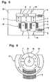
- Such a statorless, oscillating linear motor is in Fig. 8 shown.
- Fig. 8 shows an embodiment of a statorless, oscillating linear motor in a schematic side view.
- the active rotor 14 is constructive as the stator 1 of in Fig. 1 illustrated embodiment and used in an analogous manner to form a magnetic field, with the aid of the rotor 2 is driven.
- the peculiarity of the active rotor 14, however, is that it is not fixed in place in contrast to the stator 1, but is suspended by means of swinging bridges 15 movably on a housing 16 of the small electrical appliance.
- the swinging bridges 15 are leaf springs, which have a relatively small spring constant and thus form only a weak coupling to the housing 16.
- the active rotor 14 is connected via a spring 10 to the housing 16 in order to obtain a vibratory system.
- the rotor 2, which is identical to the in Fig. 1 illustrated embodiment is connected via swinging bridges 15 and a spring 10 to the housing 16. In this case, a single runner 2 or it can be provided a plurality of runners 2.
- Fig. 8 illustrated embodiment of the embodiment according to Fig. 1 in that the active rotor 14 is also set in a vibratory motion.
- the oscillatory motion of the active rotor 14 runs in antiphase to the oscillatory motion of the rotor 2.
- the individual control of the vibration movements meet those for the in Fig. 1 illustrated Embodiment of the linear motor with the stator 1 made information also for the present embodiment with the active rotor 14, wherein the active rotor 14 with respect to its oscillatory motion behaves like a conventional rotor 2.
- an oscillating linear motor can be used, for example, in an electric shaver.
- the in Fig. 8 illustrated embodiment can be used in a corresponding manner.
- the rotor 2 and the active rotor 14 are each connected to one of the two blades.
- the resonant frequencies of the two oscillatory systems ie, the two rotor 2 or the active rotor 14 and the rotor 2 and the respectively associated shear blade and the associated springs 10, slightly different choices.
- an electrical signal is generated which contains only one frequency, which lies between the two resonance frequencies.
- the two runners 2 and the rotor 2 and the active rotor 14 are driven so that they oscillate with the same frequency, the same amplitude and out of phase, so that only relatively small housing vibrations result.
- the magnet arrangements of the two rotor 2 are poled differently, to produce antiphase oscillations.
- a long-hair trimmer and possibly also a center cutter of the razor with the oscillating linear motor.
- a corresponding number of runners 2 are provided, which drive the respective components of the shaver.
- the electrical signal to drive the coil 6 is formed so that it additionally contains the resonance frequencies for the corresponding vibration systems, so that the runners 2, which drive the long-hair trimmer and the center cutter, can be selectively placed in a vibrational state.
- the cutting devices whose resonance frequencies are not included in the electrical signal, not driven, and are thus turned off.
- control method according to the invention can be applied not only to oscillating linear motors but also to oscillating rotary motors.
- Fig. 9 shows an embodiment of a statorless, oscillating rotary motor in a schematic side view.
- the statorless rotary motor has similar functional components as in Fig. 8 illustrated statorless linear motor. However, these functional components are each modified so that instead of an oscillating linear movement, an oscillating rotational movement arises.
- the statorless ration motor on an outer rotor 17 which is rotatably suspended and consists of a ferrous material.
- the outer rotor 17 extends partially within the coil 6 without touching, however, so that the outer rotor 17 can be rotated relative to the stationarily arranged coil 6.
- an inner rotor 18 is arranged, which has a rotor core 19 made of a ferrous material and permanent magnets 7 attached thereto.
- the inner rotor 18 is also rotatably suspended, wherein the outer rotor 17 and the inner rotor 18 have a common axis of rotation 20.
- the rotary motor still has a number of spring elements, which are arranged between the outer rotor 17 and the housing 16 and the inner rotor 18 and the housing 16 and for reasons of clarity in Fig. 9 are not shown.
- the rotary motor thus has two oscillatory systems. With regard to the control of the rotary motor, the above explanations apply to the control of the linear motor in an analogous manner.
- the rotary motor can be used for example as a drive for an electric toothbrush, wherein the in Fig. 9 illustrated embodiment of the rotary motor allows two different cleaning movements.
Abstract
Description
Die Erfindung bezieht sich auf ein Verfahren zur Steuerung eines Elektromotors mit mehreren schwingungsfähigen Motorkomponenten zum Antreiben eines elektrischen Kleingeräts. Weiterhin bezieht sich die Erfindung auf ein elektrisches Kleingerät mit einem Elektromotor, der mehrere schwingungsfähige Motorkomponenten aufweist.The invention relates to a method for controlling an electric motor having a plurality of oscillatory engine components for driving a small electrical appliance. Furthermore, the invention relates to a small electrical appliance with an electric motor having a plurality of oscillatory engine components.
Es ist bereits bekannt, Elektromotoren für elektrische Kleingeräte, beispielsweise elektrische Rasierapparate, mit mehreren schwingungsfähigen Motorkomponenten auszustatten. So offenbart die
Weiterhin ist aus der
Der Erfindung liegt die Aufgabe zugrunde, ein elektrisches Kleingerät auf möglichst optimale Weise anzutreiben.The invention has for its object to drive a small electrical appliance in the best possible way.
Diese Aufgabe wird durch ein Verfahren gemäß Anspruch 1 gelöst.This object is achieved by a method according to
Beim erfindungsgemäßen Verfahren zur Steuerung eines Elektromotors mit mehreren schwingungsfähigen Motorkomponenten zum Antreiben eines elektrischen Kleingeräts werden die schwingungsfähigen Motorkomponenten durch ein Magnetfeld, das von einer Spule gemeinsam für die schwingungsfähigen Motorkomponenten erzeugt wird, in Schwingungsbewegungen versetzt. Die Besonderheit des erfindungsgemäßen Verfahrens besteht dabei darin, daß die Schwingungsbewegungen der schwingungsfähigen Motorkomponenten mittels eines elektrischen Signals, das der Spule zugeführt wird, individuell gesteuert werden.In the method according to the invention for controlling an electric motor having a plurality of oscillatory engine components for driving a small electrical appliance, the oscillatory engine components are vibrated by a magnetic field generated by a coil in common for the oscillatory engine components. The peculiarity of the method according to the invention consists in the fact that the oscillatory movements of the oscillatory engine components are controlled individually by means of an electrical signal which is supplied to the coil.
Die Erfindung hat den Vorteil, daß mit einem vergleichsweise geringen Aufwand mehrere individuell steuerbare Antriebsbewegungen zur Verfügung gestellt werden können. Alle Antriebsbewegungen werden mittels einer gemeinsamen Spule erzeugt, deren Magnetfeld auf die jeweils mit einer Anordnung von Dauermagneten ausgestatteten, schwingungsfähigen Motorkomponenten einwirkt und diese dadurch direkt antreibt. Das erfindungsgemäße Verfahren ermöglicht somit die Realisierung verschiedener Antriebsfunktionen mit einem einzigen Motor, der einen sehr einfachen mechanischen und magnetischen Aufbau besitzt. Ein Getriebe oder andere Hilfsmittel zur Beeinflussung der Antriebsbewegungen werden nicht benötigt, so daß auch die dadurch verursachten Kosten und die damit einhergehenden Reibungsverluste entfallen. Außerdem ergibt sich dadurch die Möglichkeit, auch relativ hohe Schwingungsfrequenzen zu erzeugen. Das beim erfindungsgemäßen Verfahren verwendete elektrische Signal ist so beschaffen, daß das daraus mit Hilfe der Spule erzeugte Magnetfeld auf die einzelnen schwingungsfähigen Motorkomponenten jeweils eine andere Wirkung entfalten kann. Dies bedeutet, daß wegen der gemeinsamen Spule das Magnetfeld zwar immer auf alle schwingungsfähigen Motorkomponenten einwirkt, das Resultat dieser Einwirkung jedoch für jede schwingungsfähige Motorkomponente anders ausfallen kann.The invention has the advantage that a plurality of individually controllable drive movements can be provided with a comparatively low effort. All drive movements are generated by means of a common coil whose magnetic field acts on each equipped with an array of permanent magnets, oscillatory engine components and thereby drives them directly. The inventive method thus enables the realization of various drive functions with a single motor, which has a very simple mechanical and magnetic structure. A gear or other aids for influencing the drive movements are not required, so that the costs incurred thereby and the associated friction losses omitted. In addition, this results in the possibility of generating relatively high vibration frequencies. The electrical signal used in the method according to the invention is such that the magnetic field generated therefrom with the aid of the coil can in each case have a different effect on the individual oscillatory engine components. This means that because of the common coil, although the magnetic field always acts on all oscillatory engine components, the result of this action can be different for each oscillatory engine component.
In einem bevorzugten Ausführungsbeispiel wird diese individuelle Beeinflussung der Schwingungsbewegungen der einzelnen schwingungsfähigen Motorkomponenten durch das Magnetfeld dadurch erreicht, daß die schwingungsfähigen Motorkomponenten jeweils Bestandteile von Schwingungssystemen mit unterschiedlichen Resonanzfrequenzen sind. Da die Wirkung einer Anregung auf ein Schwingungssystem von dessen Resonanzfrequenz abhängt, entfaltet das Magnetfeld in der Regel für jede schwingungsfähige Motorkomponente eine andere Wirkung. Deshalb ist es beispielsweise möglich, die Schwingungsbewegungen der schwingungsfähigen Motorkomponenten jeweils über die Vorgabe der Frequenz des der Spule zugeführten elektrischen Signals individuell zu steuern. Abhängig davon, wie stark diese Frequenz von den einzelnen Resonanzfrequenzen abweicht, werden die Schwingungsbewegungen der schwingungsfähigen Motorkomponenten durch das mit dem Signal erzeugte Magnetfeld unterschiedlich beeinflußt.In a preferred embodiment, this individual influencing of the oscillatory movements of the individual oscillatory engine components by the magnetic field is achieved in that the oscillatory engine components are each components of vibration systems with different resonance frequencies. Since the effect of excitation on a vibratory system depends on its resonant frequency, the magnetic field typically develops a different effect for each oscillatory engine component. For this reason, it is possible, for example, to individually control the oscillatory movements of the oscillatory engine components via the specification of the frequency of the electrical signal supplied to the coil. Depending on how much this frequency deviates from the individual resonance frequencies, the Vibration movements of the oscillatory engine components differently influenced by the magnetic field generated by the signal.
Eine weitere Ansteuermöglichkeit besteht darin, daß das der Spule zugeführte elektrische Signal mehrere unterschiedliche Frequenzen enthält und die Schwingungsbewegungen der schwingungsfähigen Motorkomponenten jeweils über die Gewichtung der einzelnen Frequenzen im elektrischen Signal individuell gesteuert werden. Dabei ist es besonders vorteilhaft, wenn die einzelnen Frequenzen den Resonanzfrequenzen der Schwingungssysteme entsprechen, die mit den schwingungsfähigen Motorkomponenten ausgebildet werden. Auf diese Art und Weise können die Schwingungsbewegungen der schwingungsfähigen Motorkomponenten nahezu unabhängig voneinander und in weiten Bereichen variiert werden.Another driving possibility is that the electric signal supplied to the coil contains several different frequencies and the vibration movements of the oscillatory engine components are individually controlled by the weighting of the individual frequencies in the electrical signal. It is particularly advantageous if the individual frequencies correspond to the resonance frequencies of the vibration systems, which are formed with the oscillatory engine components. In this way, the oscillatory movements of the oscillatory engine components can be varied almost independently and within wide ranges.
Das elektrische Signal kann der Spule in Form von Pulsen zugeführt werden. Dabei können die Schwingungsbewegungen der schwingungsfähigen Motorkomponenten jeweils über die Vorgabe eines Pulsmusters für das der Spule zugeführte elektrische Signal individuell gesteuert werden. Die Verwendung von Pulsen hat den Vorteil, daß die Signalerzeugung sehr wenig Aufwand erfordert und das Verfahren insbesondere auch bei elektrischen Kleingeräten eingesetzt werden kann, die nicht über einen Netzanschluß verfügen, sondern mit Batterien oder Akkus betrieben werden.The electrical signal can be supplied to the coil in the form of pulses. In this case, the oscillatory movements of the oscillatory engine components can each be individually controlled via the specification of a pulse pattern for the electric signal supplied to the coil. The use of pulses has the advantage that the signal generation requires very little effort and the method can be used in particular also in small electrical appliances that do not have a network connection, but are operated with batteries or rechargeable batteries.
Mit dem erfindungsgemäßen Verfahren können insbesondere die Schwingungsamplituden der schwingungsfähigen Motorkomponenten mittels des der Spule zugeführten elektrischen Signals individuell gesteuert werden. Im Extremfall können die Schwingungsamplituden der schwingungsfähigen Motorkomponenten bis auf Null reduziert werden, so daß die schwingungsfähigen Motorkomponenten mittels des der Spule zugeführten elektrischen Signals individuell ein- oder ausgeschaltet werden. Dadurch läßt sich ohne zusätzlichen apparativen Aufwand eine automatisierte Ein- und Ausschaltung einzelner Antriebsfunktionen realisieren.With the method according to the invention, in particular the oscillation amplitudes of the oscillatory engine components can be controlled individually by means of the electrical signal supplied to the coil. In extreme cases, the vibration amplitudes of the oscillatory engine components can be reduced to zero, so that the oscillatory engine components are individually switched on or off by means of the electric signal supplied to the coil. As a result, an automated switching on and off of individual drive functions can be realized without additional equipment.
In einem bevorzugten Ausführungsbeispiel werden die Kenngrößen der tatsächlichen Schwingungsbewegungen der schwingungsfähigen Motorkomponenten mit Hilfe von Sensoren individuell für die schwingungsfähigen Motorkomponenten erfaßt. Als Kenngrößen der tatsächlichen Schwingungsbewegungen der schwingungsfähigen Motorkomponenten können jeweils insbesondere die Amplitude und/oder Frequenz und/oder Phase dienen. Die Kenngrößen können für die Steuerung der Schwingungsbewegungen der schwingungsfähigen Motorkomponenten verwendet werden, d. h. daß die Erzeugung des der Spule zugeführten elektrischen Signals jeweils abhängig von den erfaßten Kenngrößen durchgeführt werden kann. Besonders vorteilhaft ist dabei es, wenn die Erzeugung des der Spule zugeführten elektrischen Signals mittels einer geschlossenen Regelschleife durchgeführt wird. Durch diese Vorgehensweise läßt sich eine sehr präzise Steuerung der Schwingungsbewegung erreichen.In a preferred embodiment, the characteristics of the actual vibration movements of the oscillatory engine components are detected individually by means of sensors for the oscillatory engine components. In particular, the amplitude and / or frequency and / or phase can serve as characteristics of the actual oscillatory movements of the oscillatory engine components. The characteristics can be used for the control of the oscillatory motions of the oscillatory engine components, that is, that the generation of the electric signal supplied to the coil is performed depending on the detected characteristics can be. It is particularly advantageous if the generation of the electrical signal supplied to the coil is carried out by means of a closed control loop. By doing so, a very precise control of the vibration movement can be achieved.
Die Erfindung betrifft weiterhin ein elektrisches Kleingerät mit einem Elektromotor, der mehrere schwingungsfähige Motorkomponenten aufweist, die mittels einer gemeinsamen Spule antreibbar sind, sowie mit einer Steuereinrichtung zur Ausgabe eines elektrischen Signals an die Spule, um wenigstens zeitweise ein Magnetfeld zur Beeinflussung der Schwingungsbewegungen der schwingungsfähigen Motorkomponenten zur erzeugen. Die Besonderheit des elektrischen Kleingeräts besteht darin, daß mit der Steuereinrichtung ein elektrisches Signal zur individuellen Beeinflussung der Schwingungsbewegungen der schwingungsfähigen Motorkomponenten erzeugbar ist.The invention further relates to a small electrical appliance with an electric motor having a plurality of oscillatory engine components which are drivable by means of a common coil, and with a control device for outputting an electrical signal to the coil to at least temporarily a magnetic field for influencing the oscillatory motions of the oscillatory engine components to generate. The peculiarity of the small electric appliance is that with the control device, an electrical signal for the individual influencing of the vibration movements of the oscillatory engine components can be generated.
Beim erfindungsgemäßen elektrischen Kleingerät kann eine der schwingungsfähigen Motorkomponenten als ein Spulenkern für die Spule ausgebildet sein. Diese schwingungsfähige Motorkomponente übernimmt somit die Funktion eines üblichen Stators, ohne allerdings ortsfest angeordnet zu sein. Dies hat den Vorteil, daß auch die als Spulenkern ausgebildete schwingungsfähige Motorkomponente eine Antriebsfunktion übernehmen kann und daß die Übertragung von unerwünschten Vibrationen vom Elektromotor auf das elektrische Kleingerät weitgehend vermieden werden kann. Dabei ist es insbesondere von Vorteil, wenn der Spulenkern relativ zur Spule beweglich angeordnet ist. Dies bedeutet, daß die Spule ortsfest angeordnet werden kann und somit leichter zu kontaktieren ist als eine bewegliche Spule. Außerdem wird die schwingende Masse relativ gering gehalten, da die Spule nicht mitschwingt.In the small electrical appliance according to the invention, one of the oscillatory engine components can be designed as a coil core for the coil. This oscillatory engine component thus assumes the function of a conventional stator, but without being arranged stationary. This has the advantage that even designed as a coil core oscillatory engine component can take over a drive function and that the transmission of unwanted vibrations from the electric motor to the electrical appliance can be largely avoided. It is particularly advantageous if the coil core is arranged to be movable relative to the coil. This means that the coil can be arranged stationary and thus easier to contact than a movable coil. In addition, the oscillating mass is kept relatively low because the coil does not resonate.
Bei einem·Ausführungsbeispiel des elektrischen Kleingeräts ist der Elektromotor als oszillierender Linearmotor ausgebildet. Eine derartige Ausbildung des Elektromotors ist beispielsweise bei einem elektrischen Rasierapparat vorgesehen. Bei einem weiteren Ausführungsbeispiel ist der Elektromotor als oszillierender Rotationsmotor ausgebildet. Dies kann beispielsweise bei einer elektrischen Zahnbürste der Fall sein.In one embodiment of the small electrical appliance, the electric motor is designed as an oscillating linear motor. Such a design of the electric motor is provided for example in an electric shaver. In a further embodiment, the electric motor is designed as an oscillating rotary motor. This may for example be the case with an electric toothbrush.
Die Erfindung wird nachstehend an Hand der in der Zeichnung dargestellten Ausführungsbeispiele näher erläutert.The invention will be explained in more detail with reference to the embodiments illustrated in the drawings.
Es zeigen:
- Fig. 1
- ein Ausführungsbeispiel für einen oszillierenden Linearmotor in einer schematischen Seitenansicht,
- Fig. 2
- die Läufer des Ausführungsbeispiels aus
Fig. 1 in einer schematischen Aufsicht, - Fig. 3
- ein Diagramm zur Veranschaulichung des Schwingungsverhaltens des in den
Fig. 1 und 2 dargestellten oszillierenden Linearmotors, - Fig. 4
- ein Blockschaltbild zur Veranschaulichung des erfindungsgemäßen Steuerverfahrens,
- Fig. 5, 6,7
- Diagramme zur Veranschaulichung der individuellen Ansteuerung von zwei Läufern eines Linearmotors,
- Fig. 8
- ein Ausführungsbeispiel für einen statorlosen, oszillierenden Linearmotor in einer schematischen Seitenansicht und
- Fig. 9
- ein Ausführungsbeispiel für einen statorlosen, oszillierenden Rotationsmotor in einer schematischen Seitenansicht.
- Fig. 1
- An exemplary embodiment of an oscillating linear motor in a schematic side view,
- Fig. 2
- the runners of the embodiment
Fig. 1 in a schematic plan, - Fig. 3
- a diagram illustrating the vibration behavior of the in the
Fig. 1 and 2 illustrated oscillating linear motor, - Fig. 4
- a block diagram for illustrating the control method according to the invention,
- Fig. 5, 6,7
- Diagrams to illustrate the individual control of two rotors of a linear motor,
- Fig. 8
- an embodiment of a statorless, oscillating linear motor in a schematic side view and
- Fig. 9
- an embodiment of a statorless, oscillating rotary motor in a schematic side view.
Im Betriebszustand des Linearmotors wird der Spule 6 ein elektrisches Signal zugeführt, so daß ein Stromfluß durch die Spule 6 hergestellt wird und sich im Eisenkern 4 ein Magnetfeld aufbaut. Insbesondere im Bereich der Stirnflächen der Schenkel 5 des Eisenkerns 4 wirkt das Magnetfeld auf die Dauermagnete 7 ein und bewirkt bei der in
Aus
Eine im Rahmen der durch die Systemparameter vorgegebenen Grenzen beliebige Einstellung der Schwingungsamplituden A der drei Läufer 2 ist durch die Verwendung mehrerer Anregungsfrequenzen f möglich. Beispielsweise können drei Anregungsfrequenzen verwendet werden, die den drei Resonanzfrequenzen f1, f2 und f3 der Läufer 2 entsprechen. Die dadurch bei den Läufern 2 erzielten Schwingungsamplituden A hängen jeweils von den Amplituden der Anregungssignale ab. Je nach Schärfe der Resonanz kann durch jedes Anregungssignal zusätzlich eine geringfügige Beeinflussung der jeweils anderen beiden Läufer 2 erfolgen. Die konkrete Anwendung der vorstehend geschilderten Prinzipien zur individuellen Steuerung der Schwingungsbewegungen der Läufer 2 wird anhand von
In
In
Bei der in
Das erfindungsgemäße Steuerverfahren kann auch zur Steuerung eines oszillierenden Linearmotors eingesetzt werden, der nicht über einen feststehenden Stator 1 verfügt, sondern über einen zusätzlichen Läufer, der konstruktiv wie der Stator 1 aufgebaut ist, jedoch beweglich ist. Ein derartiger statorloser, oszillierender Linearmotor ist in
In seiner Funktionsweise unterscheidet sich das in
Die vorstehend beschriebenen Ausführungsbeispiele für einen oszillierenden Linearmotor können beispielsweise bei einem elektrischen Rasierapparat eingesetzt werden. Dies gilt sowohl für das in
Weiterhin ist es auch möglich, mit dem oszillierenden Linearmotor zusätzlich einen Langhaarschneider und ggf. auch einen Mittelschneider des Rasierapparats anzutreiben. Hierzu wird bei dem in
Das erfindungsgemäße Steuerverfahren kann nicht nur bei oszillierenden Linearmotoren, sondern auch bei oszillierenden Rotationsmotoren angewendet werden.The control method according to the invention can be applied not only to oscillating linear motors but also to oscillating rotary motors.
Der Rotationsmotor kann beispielsweise als Antrieb für eine elektrische Zahnbürste verwendet werden, wobei das in
Claims (20)
- A method of controlling an electric motor comprising several oscillatory motor components (2, 14, 17, 18) for the purpose of driving a small electric appliance, said oscillatory motor components (2, 14, 17, 18) being excited into oscillatory motion by means of a magnetic field which is jointly generated by a coil (6) for the oscillatory motor components (2, 14, 17, 18), characterized in that the oscillation movements of the oscillatory motor components (2, 14, 17, 18) are controlled individually by means of an electric signal which is supplied to the coil (6).
- The method according to claim 1, characterized in that the oscillatory motor components (2, 14, 17, 18) are each components of oscillatory systems with different resonant frequencies.
- The method according to any one of the preceding claims, characterized in that the oscillation movements of the oscillatory motor components (2, 14, 17, 18) are individually controlled by presetting the frequency of the electric signal supplied to the coil (6).
- The method according to any one of the claims 1 or 2, characterized in that the electric signal which is supplied to the coil (6) includes several different frequencies, and the oscillation movements of the oscillatory motor components (2, 14, 17, 18) are individually controlled by weighting the individual frequencies in the electric signal.
- The method according to claim 4, characterized in that the individual frequencies correspond to the resonant frequencies of the oscillatory systems which are formed by the oscillatory motor components (2, 14, 17, 18).
- The method according to any one of the preceding claims, characterized in that the electric signal is supplied to the coil (6) in the form of pulses.
- The method according to claim 6, characterized in that the oscillation movements of the oscillatory motor components (2, 14, 17, 18) are individually controlled by presetting a pulse pattern for the electric signal which is supplied to the coil (6).
- The method according to any one of the preceding claims, characterized in that the oscillation amplitudes of the oscillatory motor components (2, 14, 17, 18) are individually controlled by means of the electric signal supplied to the coil (6).
- The method according to any one of the preceding claims, characterized in that the oscillatory motor components (2, 14, 17, 18) are switched on or off individually by means of the electric signal which is supplied to the coil (6).
- The method according to any one of the preceding claims, characterized in that characteristic quantities of the actual oscillation movements of the oscillatory motor components (2, 14, 17, 18) are detected individually for the oscillatory motor components (2, 14, 17, 18) with the aid of sensors (12).
- The method according to claim 10, characterized in that the amplitude and/or frequency and/or phase serve as characteristic quantities of the actual oscillation movements of the oscillatory motor components (2, 14, 17, 18).
- The method according to any one of the claims 10 or 11, characterized in that the electric signal which is supplied to the coil (6) is generated as a function of the detected characteristic quantities.
- The method according to any one of the claims 10 to 12, characterized in that the generation of the electric signal fed to the coil (6) is performed by means of a closed control loop.
- A small electric appliance having an electric motor with several oscillatory motor components (2, 14, 17, 18) adapted to be driven by a shared coil (6), and further having a control device (11) for outputting an electric signal to the coil (6) for the purpose of at least temporarily generating a magnetic field which influences the oscillation movements of the oscillatory motor components (2, 14, 17, 18), characterized in that an electric signal which individually influences the oscillation movements of the oscillatory motor components (2, 14, 17, 18) can be generated by means of the control device (11).
- The small electric appliance according to claim 14, characterized in that one of the oscillatory motor components (14, 17) is constructed as a coil core for the coil (6).
- The small electric appliance according to claim 15, characterized in that the oscillatory motor component (17) constructed as coil core is arranged for movement relative to the coil (6).
- The small electric appliance according to any one of the claims 14 to 16, characterized in that the electric motor is constructed as a linear oscillation motor.
- The small electric appliance according to claim 17, characterized in that it is constructed as an electric shaving apparatus.
- The small electric appliance according to any one of the claims 14 to 16, characterized in that the electric motor is constructed as a rotary oscillation motor.
- The small electric appliance according to claim 19, characterized in that it is constructed as an electric toothbrush.
Applications Claiming Priority (2)
| Application Number | Priority Date | Filing Date | Title |
|---|---|---|---|
| DE10330979A DE10330979A1 (en) | 2003-07-09 | 2003-07-09 | Method for controlling an electric motor with a plurality of oscillatory engine components |
| PCT/EP2004/006198 WO2005006521A1 (en) | 2003-07-09 | 2004-06-09 | Method for controlling an electric motor comprising several oscillating motor components |
Publications (2)
| Publication Number | Publication Date |
|---|---|
| EP1642380A1 EP1642380A1 (en) | 2006-04-05 |
| EP1642380B1 true EP1642380B1 (en) | 2008-10-08 |
Family
ID=34041722
Family Applications (1)
| Application Number | Title | Priority Date | Filing Date |
|---|---|---|---|
| EP04736383A Not-in-force EP1642380B1 (en) | 2003-07-09 | 2004-06-09 | Method for controlling an electric motor comprising several oscillating motor components |
Country Status (4)
| Country | Link |
|---|---|
| EP (1) | EP1642380B1 (en) |
| AT (1) | ATE410813T1 (en) |
| DE (2) | DE10330979A1 (en) |
| WO (1) | WO2005006521A1 (en) |
Families Citing this family (1)
| Publication number | Priority date | Publication date | Assignee | Title |
|---|---|---|---|---|
| DE102005045800A1 (en) * | 2005-09-24 | 2007-04-05 | Braun Gmbh | Electric shaver comprises a control unit for controlling a rotating motor so that a first blade oscillates linearly and has a prescribed oscillating amplitude |
Family Cites Families (7)
| Publication number | Priority date | Publication date | Assignee | Title |
|---|---|---|---|---|
| NL271185A (en) * | 1960-09-29 | |||
| FR2179653B1 (en) * | 1972-04-13 | 1974-07-26 | Crouzet Sa | |
| CN1045915C (en) * | 1994-03-28 | 1999-10-27 | 松下电工株式会社 | Reciprocatory dry shaver |
| JP3382007B2 (en) * | 1994-03-28 | 2003-03-04 | 松下電工株式会社 | Reciprocating electric razor |
| EP0952663B1 (en) * | 1998-04-23 | 2007-11-21 | Matsushita Electric Works, Ltd. | Driving circuit for oscillatory actuator |
| JP3791402B2 (en) * | 2001-01-26 | 2006-06-28 | 松下電工株式会社 | Drive control method and drive control apparatus for linear vibration motor |
| US6548971B2 (en) * | 2001-05-22 | 2003-04-15 | Matsushita Electric Works, Ltd. | Dual sided self-oscillation circuit for driving an oscillatory actuator |
-
2003
- 2003-07-09 DE DE10330979A patent/DE10330979A1/en not_active Withdrawn
-
2004
- 2004-06-09 DE DE502004008215T patent/DE502004008215D1/en active Active
- 2004-06-09 EP EP04736383A patent/EP1642380B1/en not_active Not-in-force
- 2004-06-09 AT AT04736383T patent/ATE410813T1/en active
- 2004-06-09 WO PCT/EP2004/006198 patent/WO2005006521A1/en active Application Filing
Also Published As
| Publication number | Publication date |
|---|---|
| WO2005006521A1 (en) | 2005-01-20 |
| EP1642380A1 (en) | 2006-04-05 |
| ATE410813T1 (en) | 2008-10-15 |
| DE502004008215D1 (en) | 2008-11-20 |
| DE10330979A1 (en) | 2005-02-10 |
Similar Documents
| Publication | Publication Date | Title |
|---|---|---|
| DE10330978A1 (en) | Small electrical appliance with an electric motor for generating an oscillating movement | |
| EP1509368B1 (en) | Drive device for generating an oscillating motion for a small electric appliance | |
| DE69501089T3 (en) | Oscillating dry shaver | |
| EP1140439B1 (en) | Actuating device for oscillating electric products of personal use, especially electric razors | |
| EP1518318B1 (en) | Method for controlling an oscillating electric motor of a small electrical appliance | |
| DE3153253C2 (en) | ||
| EP1539437B1 (en) | Small electrical appliance with a drive device for generation of an oscillating movement | |
| EP2220760B1 (en) | Arrangement having oscillating motor and method for controlling an oscillating motor | |
| EP1687887A1 (en) | Electric motor for an electrical small-scale unit | |
| EP1108283A1 (en) | Electromagnetic actuator with an oscillating spring-mass system | |
| DE102005060537A1 (en) | Electric shaver with oscillating shaving head | |
| EP1678813B1 (en) | Drive unit for generating an oscillatory motion for electrical small-scale units | |
| EP2262084A1 (en) | Electric motor for an electric appliance | |
| DE10242094B4 (en) | Drive device for generating an oscillating movement for a small electrical appliance | |
| EP1539439B1 (en) | Small electrical appliance with a drive device for generation of an oscillating movement | |
| EP0937328B1 (en) | Electromotive adjustable drive | |
| WO2005120781A1 (en) | Electric shaving appliance comprising a pivotable shaving head | |
| EP1642380B1 (en) | Method for controlling an electric motor comprising several oscillating motor components | |
| DE60119648T2 (en) | Device and method for driving or controlling an actuator | |
| EP3745584B1 (en) | Kinetic energy harvester with adjustable natural frequency | |
| EP3300572B1 (en) | Cutting assembly for an agricultural harvester | |
| EP1539438A1 (en) | Drive device for the generation of an oscillating movement for a small electrical appliance | |
| DE10019226B4 (en) | Electromechanical linear actuator with torque compensation |
Legal Events
| Date | Code | Title | Description |
|---|---|---|---|
| PUAI | Public reference made under article 153(3) epc to a published international application that has entered the european phase |
Free format text: ORIGINAL CODE: 0009012 |
|
| 17P | Request for examination filed |
Effective date: 20051201 |
|
| AK | Designated contracting states |
Kind code of ref document: A1 Designated state(s): AT BE BG CH CY CZ DE DK EE ES FI FR GB GR HU IE IT LI LU MC NL PL PT RO SE SI SK TR |
|
| DAX | Request for extension of the european patent (deleted) | ||
| 17Q | First examination report despatched |
Effective date: 20070313 |
|
| GRAP | Despatch of communication of intention to grant a patent |
Free format text: ORIGINAL CODE: EPIDOSNIGR1 |
|
| GRAS | Grant fee paid |
Free format text: ORIGINAL CODE: EPIDOSNIGR3 |
|
| GRAA | (expected) grant |
Free format text: ORIGINAL CODE: 0009210 |
|
| AK | Designated contracting states |
Kind code of ref document: B1 Designated state(s): AT BE BG CH CY CZ DE DK EE ES FI FR GB GR HU IE IT LI LU MC NL PL PT RO SE SI SK TR |
|
| REG | Reference to a national code |
Ref country code: GB Ref legal event code: FG4D Free format text: NOT ENGLISH |
|
| REG | Reference to a national code |
Ref country code: CH Ref legal event code: EP |
|
| REG | Reference to a national code |
Ref country code: IE Ref legal event code: FG4D Free format text: LANGUAGE OF EP DOCUMENT: GERMAN |
|
| REF | Corresponds to: |
Ref document number: 502004008215 Country of ref document: DE Date of ref document: 20081120 Kind code of ref document: P |
|
| PG25 | Lapsed in a contracting state [announced via postgrant information from national office to epo] |
Ref country code: SI Free format text: LAPSE BECAUSE OF FAILURE TO SUBMIT A TRANSLATION OF THE DESCRIPTION OR TO PAY THE FEE WITHIN THE PRESCRIBED TIME-LIMIT Effective date: 20081008 |
|
| NLV1 | Nl: lapsed or annulled due to failure to fulfill the requirements of art. 29p and 29m of the patents act | ||
| PG25 | Lapsed in a contracting state [announced via postgrant information from national office to epo] |
Ref country code: ES Free format text: LAPSE BECAUSE OF FAILURE TO SUBMIT A TRANSLATION OF THE DESCRIPTION OR TO PAY THE FEE WITHIN THE PRESCRIBED TIME-LIMIT Effective date: 20090119 Ref country code: BG Free format text: LAPSE BECAUSE OF FAILURE TO SUBMIT A TRANSLATION OF THE DESCRIPTION OR TO PAY THE FEE WITHIN THE PRESCRIBED TIME-LIMIT Effective date: 20090108 |
|
| PG25 | Lapsed in a contracting state [announced via postgrant information from national office to epo] |
Ref country code: NL Free format text: LAPSE BECAUSE OF FAILURE TO SUBMIT A TRANSLATION OF THE DESCRIPTION OR TO PAY THE FEE WITHIN THE PRESCRIBED TIME-LIMIT Effective date: 20081008 Ref country code: PL Free format text: LAPSE BECAUSE OF FAILURE TO SUBMIT A TRANSLATION OF THE DESCRIPTION OR TO PAY THE FEE WITHIN THE PRESCRIBED TIME-LIMIT Effective date: 20081008 Ref country code: FI Free format text: LAPSE BECAUSE OF FAILURE TO SUBMIT A TRANSLATION OF THE DESCRIPTION OR TO PAY THE FEE WITHIN THE PRESCRIBED TIME-LIMIT Effective date: 20081008 Ref country code: PT Free format text: LAPSE BECAUSE OF FAILURE TO SUBMIT A TRANSLATION OF THE DESCRIPTION OR TO PAY THE FEE WITHIN THE PRESCRIBED TIME-LIMIT Effective date: 20090218 |
|
| REG | Reference to a national code |
Ref country code: IE Ref legal event code: FD4D |
|
| PG25 | Lapsed in a contracting state [announced via postgrant information from national office to epo] |
Ref country code: RO Free format text: LAPSE BECAUSE OF FAILURE TO SUBMIT A TRANSLATION OF THE DESCRIPTION OR TO PAY THE FEE WITHIN THE PRESCRIBED TIME-LIMIT Effective date: 20081008 Ref country code: DK Free format text: LAPSE BECAUSE OF FAILURE TO SUBMIT A TRANSLATION OF THE DESCRIPTION OR TO PAY THE FEE WITHIN THE PRESCRIBED TIME-LIMIT Effective date: 20081008 Ref country code: EE Free format text: LAPSE BECAUSE OF FAILURE TO SUBMIT A TRANSLATION OF THE DESCRIPTION OR TO PAY THE FEE WITHIN THE PRESCRIBED TIME-LIMIT Effective date: 20081008 Ref country code: IE Free format text: LAPSE BECAUSE OF FAILURE TO SUBMIT A TRANSLATION OF THE DESCRIPTION OR TO PAY THE FEE WITHIN THE PRESCRIBED TIME-LIMIT Effective date: 20081008 |
|
| PLBE | No opposition filed within time limit |
Free format text: ORIGINAL CODE: 0009261 |
|
| STAA | Information on the status of an ep patent application or granted ep patent |
Free format text: STATUS: NO OPPOSITION FILED WITHIN TIME LIMIT |
|
| PG25 | Lapsed in a contracting state [announced via postgrant information from national office to epo] |
Ref country code: CZ Free format text: LAPSE BECAUSE OF FAILURE TO SUBMIT A TRANSLATION OF THE DESCRIPTION OR TO PAY THE FEE WITHIN THE PRESCRIBED TIME-LIMIT Effective date: 20081008 Ref country code: SE Free format text: LAPSE BECAUSE OF FAILURE TO SUBMIT A TRANSLATION OF THE DESCRIPTION OR TO PAY THE FEE WITHIN THE PRESCRIBED TIME-LIMIT Effective date: 20090108 |
|
| 26N | No opposition filed |
Effective date: 20090709 |
|
| PG25 | Lapsed in a contracting state [announced via postgrant information from national office to epo] |
Ref country code: SK Free format text: LAPSE BECAUSE OF FAILURE TO SUBMIT A TRANSLATION OF THE DESCRIPTION OR TO PAY THE FEE WITHIN THE PRESCRIBED TIME-LIMIT Effective date: 20081008 |
|
| BERE | Be: lapsed |
Owner name: BRAUN G.M.B.H. Effective date: 20090630 |
|
| PG25 | Lapsed in a contracting state [announced via postgrant information from national office to epo] |
Ref country code: MC Free format text: LAPSE BECAUSE OF NON-PAYMENT OF DUE FEES Effective date: 20090630 |
|
| REG | Reference to a national code |
Ref country code: CH Ref legal event code: PL |
|
| PG25 | Lapsed in a contracting state [announced via postgrant information from national office to epo] |
Ref country code: CH Free format text: LAPSE BECAUSE OF NON-PAYMENT OF DUE FEES Effective date: 20090630 Ref country code: LI Free format text: LAPSE BECAUSE OF NON-PAYMENT OF DUE FEES Effective date: 20090630 |
|
| PG25 | Lapsed in a contracting state [announced via postgrant information from national office to epo] |
Ref country code: BE Free format text: LAPSE BECAUSE OF NON-PAYMENT OF DUE FEES Effective date: 20090630 |
|
| PG25 | Lapsed in a contracting state [announced via postgrant information from national office to epo] |
Ref country code: GR Free format text: LAPSE BECAUSE OF FAILURE TO SUBMIT A TRANSLATION OF THE DESCRIPTION OR TO PAY THE FEE WITHIN THE PRESCRIBED TIME-LIMIT Effective date: 20090109 |
|
| PG25 | Lapsed in a contracting state [announced via postgrant information from national office to epo] |
Ref country code: LU Free format text: LAPSE BECAUSE OF NON-PAYMENT OF DUE FEES Effective date: 20090609 |
|
| PG25 | Lapsed in a contracting state [announced via postgrant information from national office to epo] |
Ref country code: HU Free format text: LAPSE BECAUSE OF FAILURE TO SUBMIT A TRANSLATION OF THE DESCRIPTION OR TO PAY THE FEE WITHIN THE PRESCRIBED TIME-LIMIT Effective date: 20090409 |
|
| PG25 | Lapsed in a contracting state [announced via postgrant information from national office to epo] |
Ref country code: TR Free format text: LAPSE BECAUSE OF FAILURE TO SUBMIT A TRANSLATION OF THE DESCRIPTION OR TO PAY THE FEE WITHIN THE PRESCRIBED TIME-LIMIT Effective date: 20081008 |
|
| PGFP | Annual fee paid to national office [announced via postgrant information from national office to epo] |
Ref country code: AT Payment date: 20110523 Year of fee payment: 8 |
|
| PG25 | Lapsed in a contracting state [announced via postgrant information from national office to epo] |
Ref country code: CY Free format text: LAPSE BECAUSE OF FAILURE TO SUBMIT A TRANSLATION OF THE DESCRIPTION OR TO PAY THE FEE WITHIN THE PRESCRIBED TIME-LIMIT Effective date: 20081008 |
|
| PGFP | Annual fee paid to national office [announced via postgrant information from national office to epo] |
Ref country code: IT Payment date: 20110614 Year of fee payment: 8 |
|
| REG | Reference to a national code |
Ref country code: AT Ref legal event code: MM01 Ref document number: 410813 Country of ref document: AT Kind code of ref document: T Effective date: 20120609 |
|
| PG25 | Lapsed in a contracting state [announced via postgrant information from national office to epo] |
Ref country code: IT Free format text: LAPSE BECAUSE OF NON-PAYMENT OF DUE FEES Effective date: 20120609 |
|
| PG25 | Lapsed in a contracting state [announced via postgrant information from national office to epo] |
Ref country code: AT Free format text: LAPSE BECAUSE OF NON-PAYMENT OF DUE FEES Effective date: 20120609 |
|
| REG | Reference to a national code |
Ref country code: FR Ref legal event code: PLFP Year of fee payment: 13 |
|
| REG | Reference to a national code |
Ref country code: FR Ref legal event code: PLFP Year of fee payment: 14 |
|
| PGFP | Annual fee paid to national office [announced via postgrant information from national office to epo] |
Ref country code: FR Payment date: 20170511 Year of fee payment: 14 Ref country code: GB Payment date: 20170607 Year of fee payment: 14 |
|
| PGFP | Annual fee paid to national office [announced via postgrant information from national office to epo] |
Ref country code: DE Payment date: 20180530 Year of fee payment: 15 |
|
| GBPC | Gb: european patent ceased through non-payment of renewal fee |
Effective date: 20180609 |
|
| PG25 | Lapsed in a contracting state [announced via postgrant information from national office to epo] |
Ref country code: FR Free format text: LAPSE BECAUSE OF NON-PAYMENT OF DUE FEES Effective date: 20180630 Ref country code: GB Free format text: LAPSE BECAUSE OF NON-PAYMENT OF DUE FEES Effective date: 20180609 |
|
| REG | Reference to a national code |
Ref country code: DE Ref legal event code: R119 Ref document number: 502004008215 Country of ref document: DE |
|
| PG25 | Lapsed in a contracting state [announced via postgrant information from national office to epo] |
Ref country code: DE Free format text: LAPSE BECAUSE OF NON-PAYMENT OF DUE FEES Effective date: 20200101 |