CN1309537C - Drive device for generating an oscillating motion for a small electric appliance - Google Patents
Drive device for generating an oscillating motion for a small electric appliance Download PDFInfo
- Publication number
- CN1309537C CN1309537C CNB028290941A CN02829094A CN1309537C CN 1309537 C CN1309537 C CN 1309537C CN B028290941 A CNB028290941 A CN B028290941A CN 02829094 A CN02829094 A CN 02829094A CN 1309537 C CN1309537 C CN 1309537C
- Authority
- CN
- China
- Prior art keywords
- drive unit
- described drive
- driver part
- parts
- driver
- Prior art date
- Legal status (The legal status is an assumption and is not a legal conclusion. Google has not performed a legal analysis and makes no representation as to the accuracy of the status listed.)
- Expired - Fee Related
Links
Images


Classifications
-
- B—PERFORMING OPERATIONS; TRANSPORTING
- B26—HAND CUTTING TOOLS; CUTTING; SEVERING
- B26B—HAND-HELD CUTTING TOOLS NOT OTHERWISE PROVIDED FOR
- B26B19/00—Clippers or shavers operating with a plurality of cutting edges, e.g. hair clippers, dry shavers
- B26B19/28—Drive layout for hair clippers or dry shavers, e.g. providing for electromotive drive
- B26B19/288—Balance by opposing oscillation
-
- B—PERFORMING OPERATIONS; TRANSPORTING
- B26—HAND CUTTING TOOLS; CUTTING; SEVERING
- B26B—HAND-HELD CUTTING TOOLS NOT OTHERWISE PROVIDED FOR
- B26B19/00—Clippers or shavers operating with a plurality of cutting edges, e.g. hair clippers, dry shavers
- B26B19/28—Drive layout for hair clippers or dry shavers, e.g. providing for electromotive drive
- B26B19/282—Motors without a rotating central drive shaft, e.g. linear motors
-
- H—ELECTRICITY
- H02—GENERATION; CONVERSION OR DISTRIBUTION OF ELECTRIC POWER
- H02K—DYNAMO-ELECTRIC MACHINES
- H02K33/00—Motors with reciprocating, oscillating or vibrating magnet, armature or coil system
- H02K33/02—Motors with reciprocating, oscillating or vibrating magnet, armature or coil system with armatures moved one way by energisation of a single coil system and returned by mechanical force, e.g. by springs
- H02K33/04—Motors with reciprocating, oscillating or vibrating magnet, armature or coil system with armatures moved one way by energisation of a single coil system and returned by mechanical force, e.g. by springs wherein the frequency of operation is determined by the frequency of uninterrupted AC energisation
Abstract
The invention relates to a drive device for generating an oscillating motion of at least one working unit of a small electric appliance. The drive device comprises a coil (4) for forming a magnetic field, which emanates from a first drive component (1) and acts on a second drive component (2), which is displaceably mounted in the small electric appliance, in such a way that said second drive component (2) begins to oscillate. The first drive component (1) is displaceably mounted in the small electric appliance in order to carry out an antiphase oscillating motion in relation to the second drive component (2).
Description
Technical field
The present invention relates to a kind of drive unit that small household appliances produce oscillating movement that is used for.
Background technology
DE 1 151 307 A disclose this drive unit.It is a kind of back and forth movement formula Motor Drive, is used to utilize the cutter head electric shaver of work done campaign back and forth, has to fixedly connected with the shell of shaver and electromagnet that U-shaped constitutes.Electromagnet extremely near be a work armature, the both sides of work armature can vibrate a balanced armature respectively is set.In working order down, drive the work armature of cutter head and the pole-face parallel oscillation of electromagnet, wherein, balanced armature is implemented a kind of anti-phase therewith oscillating movement, is delivered on the shaver shell with the vibration of avoiding the work armature as far as possible.
DE 196 80 506 T1 disclose a kind of oscillating linear motor, have fixing electromagnet and a plurality of moving-member that utilizes electromagnet displacement in oscillating movement inverting each other.Even for also keep moving-member phase relation each other under load, these parts connect by means of a guiding mechanism to each other, the latter is being delivered to oscillating movement on another moving-member from a moving-member under the reverses its direction.
DE 197 81 664 C2 disclose a kind of electric shaver that has linear actuating device, and this drive unit has the stator of the hollow cylinder formation of charged magnet coil.Two moving-members are set in the stator, their transmissions inverting each other, one of them transmission cutter head, another can have counterweight for suppressing undesirable vibration.
Summary of the invention
The object of the present invention is to provide a kind of drive unit, be used to have the small household appliances that improve characteristic and produce oscillating movement.
This purpose realizes by the drive unit that a kind of at least one working cell that is used for small household appliances produces oscillating movement, this drive unit has a coil that is used to constitute magnetic field, this magnetic field is from first driver part and act on second driver part that is arranged on movably in the small household appliances like this, makes the second driver part oscillating movement.First driver part is to carry out with the anti-phase oscillating movement of second driver part and be arranged in the small household appliances movably.By these two driver part vibrations inverting each other, obtained relative velocity is apparently higher than driver part motion only and the static traditional drive unit of another driver part between the driver part.Because efficient can reach than the higher efficient of comparable known drive unit so utilize according to drive unit of the present invention along with driver part relative velocity each other improves in this drive unit.
At least one of two driver parts can have one or more permanent magnet.One or more winding core of coil is set above therefore, at least one of two driver parts can have.Can realize high-power drive unit under quite little size thus, its power consumption is very low, thereby for example battery just is enough to make this small household appliances work.
According in the drive unit of the present invention, can have the elastomeric element that at least one is used to produce turning power.Constitute a kind of preferably under condition of resonance, work thus and have the system of vibration ability.
Advantage in addition is that first driver part and second driver part are by the mutual mechanical connection of at least one connector.Guarantee to strictly observe the anti-phase property of two driver part oscillating movements thus.Particularly connector is rotatable respectively is hinged on first driver part and second driver part.In this regard, anti-phase property produces with the rotatable support of simple especially mode by connector.In a particularly preferred embodiment, the connector rotatable support is being used for that drive unit is fixed on fixed axis on the small household appliances.Therefore this point is applicable to this, because the point of rotation of connector does not move and can be fixed on the small household appliances without a doubt.Fixed axis can be arranged on the center between connector hinged on first driver part and second driver part.The advantage of doing like this is, even under the different load of driver part, also can observe the amplitude homogeny that the oscillating movement of two driver parts form thereupon.What have advantage for many purposes is that connector constitutes as rotating beam.Also in other constitute, connector has at least one additional driving tap and is used for the tap oscillating movement at this, and this oscillating movement has the amplitude that is different from the vibration of first and second driver parts.The advantage of doing like this is, for providing additional oscillating movement to need not transmission mechanism and therefore having reduced cost and improved reliability.
According to a scheme of the present invention, drive unit constitutes as linear motor, and wherein two driver parts can move relative to each other, thereby forms the linear osccilation campaign.In a preferred embodiment of linear motor, elastic component constitutes as spring leaf, is fixed on first driver part and second driver part.Therefore spring leaf reacts on two driver part skews respect to one another, and advantage is that spring leaf only needs few structure space.Particularly spring leaf is fixed at least one driver part with the gap vertical with the direction of motion of driver part respectively, thereby can make spring leaf along with bending reduces length.This point also can select to realize thus, promptly connector respectively with the clearance hinge vertical with the direction of motion of driver part at least one driver part.
Connector is rotatable to be hinged on the guiding lever, the latter respectively with from hinge point progressively away from driver part be connected.The result of this measure is, two driver parts are maximum mutually close on the equilbrium position, and when skew from the equilbrium position away from each other.
In a preferred embodiment, by the quality of first driver part and connector the long-pending of the distance between the articulated position of first driver part and fixed axis with identical by amassing of the quality of second driver part and the distance of connector between the articulated position of second driver part and fixed axis.The advantage of doing like this is the vibration that is delivered on the small household appliances can be remained on the very little degree.
In framework of the present invention, two driver parts can identically constitute, thereby can keep very low manufacturing cost.In addition, the winding core also can move setting with respect to coil.Because coil is not with the motion of winding core in such an embodiment,, thereby reduce the vibration on the small household appliances so the moving mass maintenance is very little.In addition, because not moving, coil can not simplify its contact contact.
First driver part and second driver part can lead by means of linear bearing.Can produce special precise linear motion in this manner.Also can obtain similar effect by following manner, promptly first driver part and second driver part keep constant distance each other by means of at least one separator.Preferred separator can particularly be bearing on the contact-making surface of first and second driver parts by flexure plane around the fixed axis rotating support.Flexure plane can be used as the cylinder fragment and constitutes, and the cylinder axis under the cylinder fragment can overlap with fixed axis respectively.
According to another program of the present invention, drive unit constitutes as swing motor, and wherein two driver parts can reverse toward each other.In foundation swing motor of the present invention, two driver parts preferably have a shared rotating shaft.Can suppress to occur undesirable vibration as far as possible thus.As the selection that rotating beam is constituted, connector for example constitutes as gear, with the gear teeth in first drive unit and the gear teeth meshing in second drive unit.
Description of drawings
The present invention will be described by the embodiment shown in the accompanying drawing below.Wherein:
Fig. 1 illustrates an embodiment of oscillating linear motor;
Fig. 2 illustrates another embodiment of oscillating linear motor;
Fig. 3 illustrates another motion state of Fig. 2 embodiment;
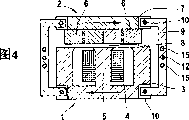
Fig. 4 illustrates another different embodiment of oscillating linear motor;
Fig. 5 illustrates an embodiment of oscillating linear motor, utilizes this motor can produce special precise linear motion;
Fig. 6 illustrates an embodiment of the identical formation of oscillating linear motor first and second parts;
Fig. 7 illustrates an embodiment of the identical formation of oscillating linear motor first and second parts that has two fixed coils;
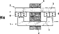
Fig. 8 illustrates another embodiment of oscillating linear motor first and second parts that have two fixed coils;
Fig. 9 illustrates an embodiment of oscillating linear motor first and second parts that have a fixed coil;
Figure 10 illustrates an embodiment of oscillatory type slewing motor;
Figure 11 illustrates another motion state of Figure 11 embodiment.
The specific embodiment
Foundation drive unit of the present invention can be used as oscillating linear motor or constitutes as the oscillatory type slewing motor.The linear movement that utilizes oscillating linear motor to produce little amplitude for example can be used on electric shaver.The oscillatory type slewing motor produces small-scale rotatablely moving, and its direction of rotation is periodically turned and for example is suitable for using in electric toothbrush.
Fig. 1 illustrates an embodiment of oscillating linear motor with simple schematic diagram.This linear motor has two moving- members 1 and 2 that are provided with very little relative distance.First parts 1 are made up of " E " shape unshakable in one's determination 3 and copper wire winding coil 4.Coil 4 is around the intermediate beam 5 of iron core 3.Second parts 2 have two permanent magnets 6, and they are arranged side by side in shared propping up on the seat board 7 with inverse parallel polarity.Propping up seat board 7 is made up of the iron material identical with unshakable in one's determination 3.Permanent magnet 6 is near the distolateral air gap 8 of 3 intermediate beams 5 unshakable in one's determination.The seat board 7 that permanent magnet 6 is set above is bearing on unshakable in one's determination 3 by two pillars 9.Two pillars 9 respectively by means of 10 rotatable support of the connecting axle in its petiolarea be fixed on unshakable in one's determination 3 and a seat board 7 on bearing pillow 11 in.Center between connecting axle 10, two pillars 9 have a fixed axis 12 separately, are used for linear motor is fixed on for example its installation site of electric shaver shell.Spring leaf 13 extends in parallel with pillar 9 between the bearing pillow 11 that is fixed on an iron core 3 and the seat board 7.
Produce following moving picture from the frame for movement of the linear motor shown in Fig. 1: first and second parts 1 and 2 carry out the basic oscillating movement that distributes in the horizontal direction in the view of Fig. 1 separately.In this regard, two parts 1 and 2 the direction of motion are opposite each other, the distribution inverting each other of just vibrating.By the accurate anti-phase property of pillar 9 by means of the rotatable suspension forced oscillation of fixed axis 12.This suspension also causes the movement locus of center of gravity of first and second parts 1 and 2 slight curving.In the view of Fig. 1, the movement locus of the center of gravity of first parts 1 is bent downwardly slightly, and the movement locus of the center of gravity of second parts 2 is bent upwards slightly.This means that the distance between first and second parts 1 and 2 that is to say that in the equilbrium position maximum shown in Fig. 1 air gap 8 is maximum on the equilbrium position.Two parts 1 and 2 are offset far more from the equilbrium position, and its distance is more little.Return the equilbrium position by the turning power driver part that produces by spring leaf 13.Not crooked and therefore do not produce turning power at equilbrium position upper spring sheet 13.Under the effect that does not have other power, therefore two parts 1 and 2 remain in the equilbrium position.Along with two parts 1 and 2 increases from the equilbrium position skew, spring leaf 13 bends to S shape gradually, thereby produces turning power on the direction of equilbrium position.S shape bending along with spring leaf 13 has reduced its longitudinal size separately.This point structurally can obtain considering thus, and promptly spring leaf 13 is with on vertically, and is just vertical with 2 the direction of motion with parts 1, minim gap be separately fixed at least one bearing pillow 11.Equally also can be suspended at least one bearing pillow 11 with the minim gap vertically by pillar 9.This gap for example can be realized by resilient suspension, perhaps realizes by the suspension that embeds in the groove that can optionally have elastic insert.
For producing two parts 1 and 2 described oscillating movements, produce electric current by coil 4.Coil 4 plays the effect of electromagnet and produces magnetic field by unshakable in one's determination 3 support, this magnetic field act on permanent magnet 6 and cause coil 4 and permanent magnet 6 between relative motion.By the corresponding control of coil 4, consequent magnetic field can change polarity separately, thus first and second parts 1 and 2 vibrations inverting each other.In this regard, an important insight of the present invention is, no matter is that first parts 1 or second parts 2 all move, and that is to say, be not used in the stator that drives rotor according to linear motor of the present invention, but two parts 1 and 2 of vibration toward each other that drive mutually.These parts 1 or a rotor that is equivalent to the conventional linear motor of 2.Another then bears the function of conventional linear motor stator, but opposite with the sort of stator, is not static and move equally.This point also causes under other identical conditions, moves each other according to first and second parts 1 of linear motor of the present invention and 2 relative velocities with one times of relative velocity between the stator that is higher than the conventional linear motor and the rotor.Can obtain quite high efficient according in the linear motor of the present invention thus.
The frequency of two parts 1 and 2 oscillating movements is predesignated by the control of coil 4 and is particularly adjusted like this, and it is equivalent to by two parts 1 and 2 and the resonant frequency of the oscillatory system that constitutes of spring leaf 13.Under condition of resonance, produce a kind of very firm vibration performance, and only need fewer energy to supply with.
Fig. 2 is to illustrate another embodiment according to linear motor of the present invention with Fig. 1 corresponding view.The main distinction of this embodiment and Fig. 1 is, for each pillar 9 distributes two guiding levers 14.Guiding lever 14 produces one separately and is rigidly connected between one of bearing pillow 11 and an iron core 3 or a seat board 7.In this regard, guiding lever 14 is not to an adjacent iron core 3 or an adjacent seat board 7 from bearing pillow 11 separately, but extends to relative separately parts, thereby guiding lever 14 intersects.Guiding lever 14 is not directly to be close on the bearing pillow 11, but clamps the spring leaf 13 that is fixed on equally by this way on the bearing pillow 11.Arranged in a crossed manner by guiding lever 14, along with its direction of motion is turned in the transverse movement that the oscillating movement of first and second parts 1 and 2 forms, the width of air gap 8 is by the transverse movement cyclically-varying.On the equilbrium position shown in Fig. 2, therefore air gap 8 is in its minimum of a value.Along with the increase of skew, air gap 8 broadens gradually.
Fig. 3 illustrates shift state for example.On this instantaneous position, first parts 1 left, second parts 2 are offset from the equilbrium position to the right.Except guiding lever 14, all corresponding on its structure and its working method according to the embodiment of Fig. 2 and 3 with the embodiment shown in Fig. 1, and when the wide variety of air gap 8, wish to occur to use under the operating position of described different situations.
Be provided with differently with the center of fixed axis 12 between connecting axle 10 shown in Fig. 1,2 and 3,, also can select eccentric the setting if wish first and second parts 1 size different with 2 amplitude.When for example using according to linear motor of the present invention on electric shaver, bottom knife can utilize big, and shearing area utilizes little amplitude operation.In addition, can also be by the position optimization vibration performance of fixed axis 12 with respect to connecting axle 10.For the vibration in fixed axis 12 zones that will be used for fixing linear motor remains on alap degree, fixed axis 12 is provided with like this, make by first parts 1 comprise with the gross mass of its fixed connecting part and the long-pending of the lever arm that acts on this quality with respect to fixed axis 12 with comprise by second parts 2 and the gross mass and the long-pending identical numerical value that has of the lever arm that acts on this quality with respect to fixed axis 12 of its fixed connecting part.
Fig. 4 is to illustrate another embodiment of oscillating linear motor with Fig. 1 corresponding view.The difference of this embodiment and Fig. 1 is, has additional driving tap 15, can be by the unit that adds according to linear electric motor of the present invention.In addition, pillar 9 is opposite with Fig. 1 not to be bar-shaped but the U-shaped formation, and utilizes its arm directly to be hinged on an iron core 3 or the seat board 7.Cancelled spring leaf 13 for the reason of general view.
Each pillar 9 has two additional driving taps 15, is separately positioned on the both sides of fixed axis 12.An additional drives tap 15 is set on the side of first parts 1 on each pillar 9, and because of itself and 1 simultaneous movements of first parts.The second additional drives tap 15 of same pillar 9 is separately positioned on the side of second parts 2, with 2 simultaneous movements of second parts and with the first additional drives tap, 15 anti-phase motion.Because it is more much closer than two connecting axles 10 of same pillar 9 that two additional drives taps 15 of this of pillar 9 are set up distance fixed axis 12, so be significantly less than the motion of first and second parts 1 and 2 from the amplitude of the motion of additional drives tap 15 taps.If it is fixed axis 12 is arranged on the center between two additional drives taps 15 of pillar 9 as shown in Figure 3, onesize from these amplitudes of motion that drive tap 15 taps so.When optimizing vibration performance, also should consider by driving the assembly that tap 15 drives.Whole momentum with null situation under produce minimum vibration.In the geometry shown in Fig. 3, when comprising that quality with first parts 1 of first parts, 1 simultaneous movements assembly equals to comprise quality with second parts 2 of second parts, 2 simultaneous movements assemblies, reach the aggregated momentum of vanishing.
The embodiment according to linear motor of the present invention shown in Fig. 4 for example can use on the electric shaver that has two blade parts.Linear motor is fixed on the shell of shaver by two fixed axis 12.Each blade part is connected on first and second parts 1 and 2, thus two blade part anti-phase motion.The cutter head of shaver and shearing area are by being connected on the additional driving tap 15 and with little amplitude driving.If shaver has two shearing areas that separate, two shearing areas also can drive on the taps 15 and with the driving inverting each other of little amplitude by being connected two.Connect in this regard and finish like this, make shearing area separately also with anti-phase the moving of blade part of distributing separately.
If do not wish first and second parts 1 and 2 above-mentioned bending movement locus and replace it and need precise linear motion, so should corresponding change first and second parts 1 and 2 forced guiding.The possibility of this change is to use linear steering, utilizes it first and second parts 1 and 2 very accurately can be forced to place on the linear movement track.In addition, also can carry out the variation shown in Fig. 5.
Fig. 5 illustrates the embodiment according to linear motor of the present invention, utilizes it can produce special precise linear motion.The corresponding selection of illustrated mode and Fig. 1, wherein, spring leaf 13 also is cancelled for the reason of general view.In this embodiment, first and second parts 1 are connected by means of two separators 16 with 2.Two separators 16 are by means of fixed axis 12 rotatable support of linear motor.On it was bearing in end face 17 on first and second parts 1 and 2 contact-making surfaces that for this reason have 18, separator 16 had a curved surface separately.
When linear motor was worked, contact-making surface 18 rolled on the end face 17 of separator 16, and separator 16 reverses around fixed axis 12.This point acts on the mechanical connection of the motion of first and second parts 1 and 2 on the one hand.Curved surface on each end face 17 constitutes so on the other hand, although make first and second parts 1 and 2 oscillating movements, still the distance of relative contact 18 equates.Shown in geometry in, this point constitutes as the cylinder fragment by end face 17 respectively and realizes that wherein, cylinder axis overlaps with fixed axis 12.Because 6 pairs of iron cores 3 of permanent magnet apply very strong gravitation, thus need not force separator 16 and unshakable in one's determination 3 or a seat board 7 between mechanical connection.But can have corresponding support or similar device.For preventing phase relation between first and second parts 1 and 2 owing to the slip or the similar effect that occur between contact-making surface 18 and the end face 17 change, the gear teeth that contact-making surface 18 and end face 17 can be used as engagement constitute.
According to the requirement of purposes separately and the structure space that can have, two parts 1 and 2 structure can change.Fig. 6-9 illustrates several embodiment of parts 1 and 2.The type of view respectively with the similar selection of Fig. 1.For example, do not illustrate for ease of observing as pillar 9 or spring leaf 13 these miscellaneous parts of linear motor.Be to constitute linear motor, these and when needing miscellaneous part replenished respectively.Because coil 4 and permanent magnet 6 parts are arranged on the same parts among several below embodiment,, these parts were also referred to as a seat board 7 so both being called unshakable in one's determination 3.For guaranteeing clearly to distribute, if adding when having coil 4 and needing, parts have permanent magnet 6, these parts just are called unshakable in one's determination 3 so.If only there is permanent magnet 6, these parts just are called a seat board 7 so.
Fig. 6 illustrates the embodiment of first and second parts 1 and 2 identical formations.Two parts 1 and 2 have the iron core 3 of a longitudinal extension separately, constitute a convex shoulder 19 on the one end.Convex shoulder 19 next doors are coils 4 of winding on unshakable in one's determination 3.In the zone of its second end, permanent magnet 6 is pasted on the next door of coil 4 on the iron core 3.The parts 1 of Gou Chenging are relative with 2 inverse parallels like this, that is to say, the convex shoulder 19 of first parts 1 is adjacent with the permanent magnet 6 of second parts 2, and the convex shoulder 19 of the permanent magnet 6 of first parts 1 and second parts 2 is adjacent.Therefore this embodiment is characterised in that, the parts 1 of phase antihunt and 2 accurately have identical quality and very closely are provided with each other.By two parts 1 and 2 identical formation, simplified manufacture process and reduced the quantity of parts to be processed.
Fig. 7 illustrates another embodiment of first and second parts 1 and 2 identical formations.The difference of this embodiment and Fig. 6 is, also has a free space separately between coil 4 and adjacent convex shoulder 19 or permanent magnets adjacent 6, and coil 4 location on unshakable in one's determination 3 separately.Therefore coil 4 does not have other part mechanical connections with parts 1 and 2, also not in company with these component movement, but fixing.Reduced on the one hand the quality of motion thus and by its vibration that causes.Simplified the contact contact of coil 4 on the other hand, because these coils do not move and therefore the contact formation is not had so high requirement.3 corresponding formations with Fig. 6 unshakable in one's determination are also carried out corresponding oscillating movement.
Fig. 8 illustrates another embodiment with fixed coil 4.This embodiment has the iron core 3 of U-shaped and bar-shaped formation.Each iron core 3 have one with small distance very around unshakable in one's determination 3 coil 4, thereby unshakable in one's determination 3 can move with respect to coil 4 separately.On bar-shaped unshakable in one's determination 3, in its stub area, paste permanent magnet 6 for this reason.Unshakable in one's determination 3 is mutually positioning like this, and the arm of the U-iron heart 3 is adjacent with bar-shaped unshakable in one's determination 3 permanent magnet 6.
Fig. 9 illustrates a kind of variation of Fig. 8 embodiment.This embodiment compares with Fig. 8 and is characterised in that and only has a coil 4.Around the U-iron heart 3, wherein, the U-iron heart 3 also can move with respect to coil 4 this coil 4 with very little rang ring, thereby the U-iron heart 3 can be finished oscillating movement in fixing coil 4.Adjacent with the arm of the U-iron heart 3 is the permanent magnet 6 that sticks on the seat board 7.
As selection, also can be used as the oscillatory type slewing motor according to drive unit of the present invention and constitute the oscillating linear motor introduced previously.Figure 10 and 11 shows respective embodiments.
Figure 10 and 11 is to illustrate under the different motion state a embodiment according to oscillatory type slewing motor of the present invention with Fig. 1 corresponding view.In Figure 10, first and second parts 1 and 2 of slewing motor are in the equilbrium position separately, and in Figure 11, first and second parts 1 and 2 are offset separately.
In an illustrated embodiment, 3 bar-shaped formations unshakable in one's determination, thereby when electric current is flowed through coil 4 around winding unshakable in one's determination, magnetic poles on unshakable in one's determination 3 end face.Near two end faces of unshakable in one's determination 3, at least one permanent magnet 6 so respectively is set, in making separately a magnetic north pole and a south magnetic pole being in the distance identical with the end face of iron core 3 side by side.Seat board 7 ring-types that permanent magnet 6 is set above constitute and around unshakable in one's determination 3 together with coil 4.Undesirable magnetic scattering field can be remained on quite little degree thus.Annular mount plate 7 overlap with unshakable in one's determination 3 center in the intracardiac central shaft 20 that is provided with, be used for swivel bearing first parts 1 and second parts 2, that is to say that no matter first parts 1 still are second parts, 2 unique freedoms of motion all is present in around among this rotation of 20.On two opposite flanks in 3 two petiolareas unshakable in one's determination a helical spring 21 is set respectively.Helical spring 21 extends to a seat board 7 from its meshing point on unshakable in one's determination 3.Under the situation that does not have the power effect, first parts 1 remain on the equilbrium position shown in Figure 10 by helical spring 21.
Rotating beam 22 utilizes the one end to turn on the petiolarea that is hinged on iron core 3.The other end of rotating beam 22 is rotatable to be hinged on the seat board 7.The jackshaft 23 that rotating beam 22 is provided with by means of the center suspension that rotatablely moves.Utilize jackshaft 23 slewing motor can also be connected thus on the device driven.Also can select to be connected on this device to this by central shaft 20.
Utilizing foundation slewing motor of the present invention to produce oscillatory type in such a way rotatablely moves:
If coil 4 has electric current to pass through, will produce the magnetic field that acts on permanent magnet 6.The result causes first and second parts 1 and 2 from its equilbrium position skew thus.Corresponding with the view of Figure 10, in the scope of this skew, top permanent magnet 6 slightly to the right and bottom permanent magnet 6 is moved to the left slightly.On the contrary, unshakable in one's determination 3 upper end slightly left and unshakable in one's determination 3 lower end moves right slightly, thereby accept the deviation post shown in Figure 11.Forced guiding by central shaft 20 causes these skews to move along an annular trace separately, just rotatablely moves.On time point, the electric currents in the coil 4 change like this, make situation opposite in the back, and permanent magnet 6 and unshakable in one's determination 3 end are offset to opposite side separately.By the corresponding control of coil 4, the vibration that therefore can produce first parts 1 and 2 distributions inverting each other of second parts rotatablely moves.This vibration rotatablely moves and supports that by helical spring 21 particularly coil 4 is controlled like this, and first and second parts 1 and 2 are vibrated with resonant frequency.In this regard, guarantee to strictly observe phase relation by rotating beam 22, rotating beam is forced the anti-phase property of two parts 1 and 2 by it in the hinged and supporting shown in Figure 10 and 11.Also can realize strictly observing phase relation by other measures.For example, also can provide with first parts 1 in the gear teeth and the gear of the gear teeth meshing in second parts 2 replace rotating beam 22.
Claims (29)
1. drive unit, at least one working cell that is used for small household appliances produces oscillating movement, have the coil (4) that is used to form magnetic field, (1) also acted on second driver part (2) that is arranged on movably in the small household appliances like this from first driver part in this magnetic field, make second driver part (2) oscillating movement, it is characterized in that first driver part (1) is arranged in the small household appliances with the anti-phase oscillating movement of second driver part (2) movably for carrying out.
2. by the described drive unit of claim 1, wherein, at least one of two driver parts (1,2) has at least one permanent magnet (6).
3. by one of aforementioned claim described drive unit, wherein, the winding core (3) of coil (4) above having, at least one of two driver parts (1,2) is set.
4. by the described drive unit of claim 1, wherein, has at least one elastomeric element that is used to produce turning power (13,21).
5. by the described drive unit of claim 1, wherein, first driver part (1) and second driver part (2) mechanically interconnect by at least one connector (9,22).
6. by the described drive unit of claim 5, wherein, connector (9,22) is hinged on first driver part (1) and second driver part (2) separately rotationally.
7. by claim 5 or 6 described drive units, wherein, connector (9,22) is mounted pivotably.
8. by the described drive unit of claim 7, wherein, connector (9,22) rotatable support is on the fixed axis (12,23) that is used for drive unit is fixed on the small household appliances.
9. by the described drive unit of claim 8, wherein, fixed axis (12,23) is arranged on the center between connector (9,22) and first driver part (1) and second driver part (2) hinged.
10. by the described drive unit of claim 5, wherein, connector (9,22) constitutes as rotating beam.
11. by the described drive unit of claim 5, wherein, connector (9,22) has at least one additional driving tap (15) and is used for the tap oscillating movement, this oscillating movement has the amplitude of the vibration that is different from first and second driver parts (1,2).
12. by the described drive unit of claim 1, wherein, drive unit constitutes as linear motor, wherein two driver parts (1,2) can move relative to each other.
13. by the described drive unit of claim 12, wherein, elastic component (13) constitutes as spring leaf, is fixed on first driver part (1) and second driver part (2).
14. by the described drive unit of claim 13, wherein, spring leaf (13) is respectively to be fixed at least one driver part (1,2) with the vertical gap of the direction of motion of driver part (1,2).
15. by claim 13 or 14 described drive units, wherein, connector (9) respectively with the vertical clearance hinge of the direction of motion of driver part (1,2) at least one driver part (1,2).
16. by the described drive unit of claim 12, wherein, connector (9) is hinged on the guiding lever (14) rotationally, the latter respectively with from hinge point progressively away from driver part (1,2) connect.
17. by the described drive unit of claim 12, wherein, by the quality of first driver part (1) and connector (9) the long-pending of the distance between the articulated position of first driver part (1) and fixed axis (12) with identical by amassing of the quality of second driver part (2) and the distance of connector (9) between the articulated position of second driver part (2) and fixed axis (12).
18. by the described drive unit of claim 12, wherein, the identical formation of two driver parts (1,2).
19. by the described drive unit of claim 12, wherein, winding core (3) is provided with movably with respect to coil (4).
20. by the described drive unit of claim 12, wherein, first driver part (1) and second driver part (2) lead by means of linear bearing.
21. by the described drive unit of claim 12, wherein, first driver part (1) and second driver part (2) keep constant distance each other by means of at least one separator (16).
22. by the described drive unit of claim 21, wherein, separator (16) can be around fixed axis (12) rotating support.
23. by claim 21 or 22 described drive units, wherein, separator (16) is bearing on the contact-making surface (18) of first and second driver parts (1,2) by flexure plane (17).
24. by the described drive unit of claim 23, wherein, flexure plane (17) constitutes as the cylinder fragment.
25. by the described drive unit of claim 24, wherein, the cylinder axis under the cylinder fragment overlaps with fixed axis (12) respectively.
26. by the described drive unit of claim 1, wherein, drive unit constitutes as swing motor, wherein two driver parts (1,2) can reverse toward each other.
27. by the described drive unit of claim 26, wherein, two driver parts (1,2) have a shared rotating shaft (20).
28. by claim 26 or 27 described drive units, wherein, connector constitutes as gear, with the gear teeth and the interior gear teeth meshing of second drive unit (2) in first drive unit (1).
29. have the small household appliances of oscillatory work unit, it is characterized in that these small household appliances have by the described drive unit of one of aforementioned claim.
Applications Claiming Priority (2)
| Application Number | Priority Date | Filing Date | Title |
|---|---|---|---|
| DE10225024.3 | 2002-06-06 | ||
| DE10225024A DE10225024A1 (en) | 2002-06-06 | 2002-06-06 | Drive device for generating an oscillating movement for a small electrical device |
Publications (2)
| Publication Number | Publication Date |
|---|---|
| CN1628013A CN1628013A (en) | 2005-06-15 |
| CN1309537C true CN1309537C (en) | 2007-04-11 |
Family
ID=29594289
Family Applications (1)
| Application Number | Title | Priority Date | Filing Date |
|---|---|---|---|
| CNB028290941A Expired - Fee Related CN1309537C (en) | 2002-06-06 | 2002-11-19 | Drive device for generating an oscillating motion for a small electric appliance |
Country Status (7)
| Country | Link |
|---|---|
| EP (1) | EP1509368B1 (en) |
| JP (1) | JP4286778B2 (en) |
| CN (1) | CN1309537C (en) |
| AT (1) | ATE383231T1 (en) |
| AU (1) | AU2002368009A1 (en) |
| DE (2) | DE10225024A1 (en) |
| WO (1) | WO2003103905A1 (en) |
Cited By (1)
| Publication number | Priority date | Publication date | Assignee | Title |
|---|---|---|---|---|
| CN107107353A (en) * | 2014-12-23 | 2017-08-29 | 博朗有限公司 | Linear motor and its support member |
Families Citing this family (27)
| Publication number | Priority date | Publication date | Assignee | Title |
|---|---|---|---|---|
| US7355305B2 (en) * | 2003-12-08 | 2008-04-08 | Shen-Etsu Chemical Co., Ltd. | Small-size direct-acting actuator |
| DE102004010847A1 (en) * | 2004-03-05 | 2005-09-22 | BSH Bosch und Siemens Hausgeräte GmbH | Linear drive device with Magnetjochkörper and permanent magnetic anchor body |
| DE602005016494D1 (en) * | 2004-06-14 | 2009-10-22 | Matsushita Electric Works Ltd | drive unit |
| DE102006034050A1 (en) * | 2006-07-20 | 2008-01-24 | Braun Gmbh | Electric shaver |
| KR20100016600A (en) * | 2007-04-18 | 2010-02-12 | 코닌클리케 필립스 일렉트로닉스 엔.브이. | Electro-mechanical massage device and wearable massage apparatus |
| WO2008129441A1 (en) | 2007-04-18 | 2008-10-30 | Koninklijke Philips Electronics N.V. | Electro-mechanical massage device and wearable massage apparatus |
| JP2009240046A (en) * | 2008-03-26 | 2009-10-15 | Panasonic Electric Works Co Ltd | Electromagnetic actuator |
| DE102008031134B4 (en) | 2008-07-01 | 2010-10-07 | Braun Gmbh | Oscillating rotary motor and electrically operated small appliance for this purpose |
| US8282268B2 (en) * | 2009-02-24 | 2012-10-09 | Island Oasis Frozen Cocktail Co., Inc. | Magnetic drive for food processing apparatus |
| KR101156787B1 (en) * | 2009-07-27 | 2012-06-18 | 삼성전기주식회사 | Linear Vibrator |
| JP2011067419A (en) * | 2009-09-25 | 2011-04-07 | Panasonic Electric Works Co Ltd | Electric razor |
| JP4875133B2 (en) * | 2009-10-29 | 2012-02-15 | 日本電産コパル株式会社 | Vibration actuator |
| WO2011077289A1 (en) * | 2009-12-23 | 2011-06-30 | Koninklijke Philips Electronics N.V. | Power toothbrush with actuator in the brushhead |
| GB2485201A (en) * | 2010-11-05 | 2012-05-09 | Mafaq Abdul Razak | Apparatus for generating an oscillating magnetic field |
| FR2971902B1 (en) * | 2011-02-23 | 2013-11-08 | Moving Magnet Tech | ELECTROMAGNETIC ACTUATOR WITH IMPROVED FORCE DENSITY AND APPLICATION TO AN ELECTRIC RAZOR |
| JP2014128188A (en) * | 2012-12-27 | 2014-07-07 | Panasonic Corp | Electric linear actuator and output shaft vibration electric drive device having the electric linear actuator |
| JP5963052B2 (en) * | 2012-12-27 | 2016-08-03 | パナソニックIpマネジメント株式会社 | Electric linear actuator and output shaft vibration type electric apparatus having the electric linear actuator |
| JP6296594B2 (en) * | 2013-09-04 | 2018-03-20 | 日本電産セイミツ株式会社 | Vibration generator |
| CN204886638U (en) * | 2015-07-31 | 2015-12-16 | 瑞声光电科技(常州)有限公司 | Micro -burst motor |
| EP3300861B1 (en) | 2016-09-28 | 2019-07-03 | Braun GmbH | Electrically driven device |
| JP6765079B2 (en) * | 2017-04-19 | 2020-10-07 | パナソニックIpマネジメント株式会社 | Vibration type linear actuator and hair treatment machine |
| EP3396821B1 (en) | 2017-04-27 | 2023-06-14 | Braun GmbH | Electric shaver |
| EP3396826B1 (en) | 2017-04-27 | 2022-10-19 | Braun GmbH | Electric appliance for personal care |
| EP3396828B1 (en) | 2017-04-27 | 2021-08-18 | Braun GmbH | Electric appliance for personal care |
| EP3396827B1 (en) | 2017-04-27 | 2023-06-28 | Braun GmbH | Electric appliance for personal care |
| ES2906953T3 (en) | 2019-05-02 | 2022-04-21 | Braun Gmbh | personal hygiene device |
| JP2023023948A (en) * | 2021-08-06 | 2023-02-16 | ミネベアミツミ株式会社 | vibration actuator |
Citations (3)
| Publication number | Priority date | Publication date | Assignee | Title |
|---|---|---|---|---|
| US4240200A (en) * | 1978-02-10 | 1980-12-23 | U.S. Philips Corporation | Dryshaving apparatus |
| US4660283A (en) * | 1985-09-20 | 1987-04-28 | Matsushita Electric Works, Ltd. | Dynamically balanced apparatus having reciprocating member |
| CN1268083A (en) * | 1997-08-23 | 2000-09-27 | 布劳恩有限公司 | Electric shaver |
Family Cites Families (10)
| Publication number | Priority date | Publication date | Assignee | Title |
|---|---|---|---|---|
| CH265598A (en) * | 1946-01-23 | 1949-12-15 | Odstrcil Borivoj | Dry shaver. |
| US2741711A (en) * | 1951-02-16 | 1956-04-10 | Schick Inc | Electric shaver vibrator motor |
| NL264048A (en) * | 1960-09-29 | |||
| GB1028215A (en) * | 1963-02-02 | 1966-05-04 | Morphy Richards Cray Ltd | Improvements relating to vibrator motors for electric dry shavers and other electro-mechanical devices |
| US3505545A (en) * | 1967-05-26 | 1970-04-07 | Ahmet K Bey | Polarized vibratory motor |
| FR2179653B1 (en) * | 1972-04-13 | 1974-07-26 | Crouzet Sa | |
| JP3266757B2 (en) * | 1995-05-26 | 2002-03-18 | 松下電工株式会社 | Vibration type linear actuator |
| WO1997035691A1 (en) * | 1996-03-26 | 1997-10-02 | Matsushita Electric Works, Ltd. | Reciprocating-type electric shaver |
| JP2000316267A (en) * | 1999-04-27 | 2000-11-14 | Matsushita Electric Works Ltd | Vibrating linear actuator |
| EP1162721B1 (en) * | 2000-06-07 | 2005-12-21 | Matsushita Electric Works, Ltd. | Linear oscillating actuator |
-
2002
- 2002-06-06 DE DE10225024A patent/DE10225024A1/en not_active Withdrawn
- 2002-11-19 AU AU2002368009A patent/AU2002368009A1/en not_active Abandoned
- 2002-11-19 CN CNB028290941A patent/CN1309537C/en not_active Expired - Fee Related
- 2002-11-19 JP JP2004511011A patent/JP4286778B2/en not_active Expired - Lifetime
- 2002-11-19 EP EP02807502A patent/EP1509368B1/en not_active Expired - Lifetime
- 2002-11-19 AT AT02807502T patent/ATE383231T1/en active
- 2002-11-19 DE DE50211537T patent/DE50211537D1/en not_active Expired - Lifetime
- 2002-11-19 WO PCT/EP2002/012929 patent/WO2003103905A1/en active IP Right Grant
Patent Citations (3)
| Publication number | Priority date | Publication date | Assignee | Title |
|---|---|---|---|---|
| US4240200A (en) * | 1978-02-10 | 1980-12-23 | U.S. Philips Corporation | Dryshaving apparatus |
| US4660283A (en) * | 1985-09-20 | 1987-04-28 | Matsushita Electric Works, Ltd. | Dynamically balanced apparatus having reciprocating member |
| CN1268083A (en) * | 1997-08-23 | 2000-09-27 | 布劳恩有限公司 | Electric shaver |
Cited By (3)
| Publication number | Priority date | Publication date | Assignee | Title |
|---|---|---|---|---|
| CN107107353A (en) * | 2014-12-23 | 2017-08-29 | 博朗有限公司 | Linear motor and its support member |
| CN107112878A (en) * | 2014-12-23 | 2017-08-29 | 博朗有限公司 | Linear motor and its support member |
| CN107112878B (en) * | 2014-12-23 | 2020-04-10 | 博朗有限公司 | Linear motor and support therefor |
Also Published As
| Publication number | Publication date |
|---|---|
| JP2005532771A (en) | 2005-10-27 |
| DE10225024A1 (en) | 2003-12-24 |
| WO2003103905A1 (en) | 2003-12-18 |
| EP1509368B1 (en) | 2008-01-09 |
| DE50211537D1 (en) | 2008-02-21 |
| AU2002368009A1 (en) | 2003-12-22 |
| JP4286778B2 (en) | 2009-07-01 |
| ATE383231T1 (en) | 2008-01-15 |
| EP1509368A1 (en) | 2005-03-02 |
| CN1628013A (en) | 2005-06-15 |
Similar Documents
| Publication | Publication Date | Title |
|---|---|---|
| CN1309537C (en) | Drive device for generating an oscillating motion for a small electric appliance | |
| US6933630B2 (en) | Drive mechanisms for small electric appliances | |
| CN100343028C (en) | Small electric appliance with a drive mechanism for generating an oscillatory motion | |
| CN101558550B (en) | Drive device for driving a brush element of an electric toothbrush | |
| CN202045073U (en) | Three-freedom-degree hybrid vibrating screen | |
| CN1096921C (en) | Vibratory linear actuator and method of driving the same | |
| CN1886885A (en) | Electric motor for a small-scale electrical appliance | |
| CN1473386A (en) | Linear motor and method of producing the same | |
| CN1647350A (en) | Vibration type linear actuator | |
| CN1808863A (en) | Linear actuator for both vibrating and rolling movement and electric toothbrush using the same | |
| CN100392951C (en) | Linear oscillating actuator system | |
| CN109391171A (en) | A kind of wind-induced vibration piezoelectricity electromagnetism combined generating device | |
| CN205911933U (en) | Electric toothbrush high -frequency vibration motor | |
| KR102281285B1 (en) | Driving system having reduced vibration transmission | |
| WO2019128689A1 (en) | Swing motor and electronic device | |
| CN102275320A (en) | High-speed pressure machine | |
| CN1581643A (en) | Electric motor, lift with a car moved with an electric motor and lift with a car capable of relative moved guiding member | |
| CN101124711A (en) | Magnetic driven actuator | |
| CN201055845Y (en) | Double-vibration source vibrating screen | |
| CN101267171B (en) | Electromagnetic voltage adjusting multi freedom degree spherical ultrasonic electromotor | |
| CN100540241C (en) | Electric shaving appliance and the electronic driver that is used to drive it | |
| US4486667A (en) | Drive system for an electric generator | |
| CN1875536A (en) | Electric drive unit for generating an oscillating displacement | |
| CN204234339U (en) | A kind of linear electric motors drive self-balancing type vibrating transportation screening machine | |
| CN101648646A (en) | Three-vibrator linear vibration feeder |
Legal Events
| Date | Code | Title | Description |
|---|---|---|---|
| C06 | Publication | ||
| PB01 | Publication | ||
| C10 | Entry into substantive examination | ||
| SE01 | Entry into force of request for substantive examination | ||
| C14 | Grant of patent or utility model | ||
| GR01 | Patent grant | ||
| CF01 | Termination of patent right due to non-payment of annual fee | ||
| CF01 | Termination of patent right due to non-payment of annual fee |
Granted publication date: 20070411 Termination date: 20181119 |