EP0349076A2 - Vibrating apparatus for household use - Google Patents
Vibrating apparatus for household use Download PDFInfo
- Publication number
- EP0349076A2 EP0349076A2 EP89201677A EP89201677A EP0349076A2 EP 0349076 A2 EP0349076 A2 EP 0349076A2 EP 89201677 A EP89201677 A EP 89201677A EP 89201677 A EP89201677 A EP 89201677A EP 0349076 A2 EP0349076 A2 EP 0349076A2
- Authority
- EP
- European Patent Office
- Prior art keywords
- rotor
- lever
- rocker arm
- vibration device
- household
- Prior art date
- Legal status (The legal status is an assumption and is not a legal conclusion. Google has not performed a legal analysis and makes no representation as to the accuracy of the status listed.)
- Granted
Links
Images


Classifications
-
- B—PERFORMING OPERATIONS; TRANSPORTING
- B26—HAND CUTTING TOOLS; CUTTING; SEVERING
- B26B—HAND-HELD CUTTING TOOLS NOT OTHERWISE PROVIDED FOR
- B26B19/00—Clippers or shavers operating with a plurality of cutting edges, e.g. hair clippers, dry shavers
- B26B19/28—Drive layout for hair clippers or dry shavers, e.g. providing for electromotive drive
- B26B19/282—Motors without a rotating central drive shaft, e.g. linear motors
-
- Y—GENERAL TAGGING OF NEW TECHNOLOGICAL DEVELOPMENTS; GENERAL TAGGING OF CROSS-SECTIONAL TECHNOLOGIES SPANNING OVER SEVERAL SECTIONS OF THE IPC; TECHNICAL SUBJECTS COVERED BY FORMER USPC CROSS-REFERENCE ART COLLECTIONS [XRACs] AND DIGESTS
- Y10—TECHNICAL SUBJECTS COVERED BY FORMER USPC
- Y10T—TECHNICAL SUBJECTS COVERED BY FORMER US CLASSIFICATION
- Y10T74/00—Machine element or mechanism
- Y10T74/18—Mechanical movements
- Y10T74/18056—Rotary to or from reciprocating or oscillating
- Y10T74/18184—Crank, pitman, and lever
Definitions
- the invention relates to a household vibration device, in particular a dry shaving or hair cutting device, in which movements of a two-pole permanent magnet designed as a rotor in a stator arrangement excited by coils generate a vibration movement of a vibration tool, specifically via a lever system which is coupled to the movements of the rotor.
- a resilient spring force acting on the lever system prestressing the drive consisting of the lever system and the rotor so that the rotor can perform oscillating movements around a rest position, wherein the lever system has a double-arm rocker arm and wherein the lever system is connected to an eccentrically arranged pin of the rotor.
- Such a household vibration device in the form of a dry shaving or hair cutting device is known from DE-PS 34 04 297.
- a single-phase synchronous motor with a two-pole, permanent-magnet rotor is used.
- special dimensions and constructive measures are necessary to ensure a safe start and the stability of the movement.
- the conversion of the rotating movements of the rotor into an oscillating movement of twice the frequency of the tool, namely a lower knife, is carried out by means of a roller cam gear.
- a spring acts on the roller cam gear, which serves on the one hand to support starting and on the other hand ensures that the roller does not lift off the cam.
- a single-phase synchronous motor is smaller than an oscillating armature motor of the same power.
- the roller cam gear has large mechanical implementation losses at the contact surface of the roller and cam.
- a time measuring device with a balance spring of a clock is known.
- the spiral balance spring limits the movements of the rotor; it vibrates essentially at a frequency which depends on the mass and spring construction of the system.
- the coil is controlled electronically.
- the motor is designed in the manner of a single-phase synchronous motor; however, it is not intended or usable as a power drive for an engine.
- the air gap is symmetrical to the center line through the stator bore parallel to the stator field direction.
- an oscillating armature motor which serves to drive a hair clipper and which has a magnet system excited by alternating current, the armature of which is actuated by its alternating poles and contains a permanent magnet which, together with its pole pieces, oscillates essentially around its central axis .
- An anchor with pole pieces is complex and has a large vibration mass.
- the stator described is also of complex construction.
- the armature carries an eccentric pin which engages in a two-armed lever connected to a movable lower knife. Because in the middle position of the lever, the connecting line of the armature shaft and rocker arm through the eccentric pin runs, the oscillation frequency of the armature and the movable knife are equal to each other. When operating on a 50 Hz network, the oscillation frequency is 50 Hz.
- a first embodiment is characterized in that the two-pole, permanent magnetic and pole shoe-free rotor is arranged in the U-shaped stator of a single-phase synchronous motor, a first lever arm of the double-armed rocker arm and the rotor are connected via a connecting rod which, on the one hand, articulates by means of a push rod joint on the first lever arm and eccentrically by means of the crank pin on the rotor, the spring force prestresses the drive such that the rest position of the rotor when the stator coils are switched off coincides with the position in which the central direction of magnetization of the rotor is approximately perpendicular to the central direction of the magnetic field of the stator arrangement, - In the rest position of the rotor, the extension of the connecting line between the push rod joint and the crank pin extends through the rotor axis, as a result of which the mechanical oscillation frequency of the oscillating lever is doubled compared to that of the rotor.
- a second embodiment is characterized in that the two-pole, permanent magnetic and pole shoe-free rotor is arranged in the U-shaped stator of a single-phase synchronous motor, the first lever arm is designed as a slot converter with a longitudinal slot into which an eccentric pin of the rotor engages, - In the rest position of the rotor, the connecting line of the eccentric pin with the rotor axis and the connecting line of the rotor axis with the rocker arm bearing form a right angle, -
- the spring force biases the drive so that the rest position of the permanent magnet designed as a rotor coincides with the stator coils switched off, with the position in which the central direction of magnetization of the rotor is approximately perpendicular to the central direction of the magnetic field of the stator arrangement, as a result of which the mechanical oscillation frequency of the oscillating lever is compared to the oscillation frequency of the rotor is doubled.
- a third embodiment is characterized in that the two-pole, permanent magnetic and pole shoe-free rotor is arranged in the U-shaped stator of a single-phase synchronous motor, a first lever arm of the double-arm rocking lever and the permanent magnet rotor are connected via a connecting rod which, on the one hand, articulates by means of a push rod joint on the first lever arm and eccentrically by means of the crank pin on the rotor, -
- the spring force biases the drive so that the rest position of the rotor when the stator coils are switched off coincides with the position in which the central direction of magnetization of the rotor is approximately perpendicular to the central direction of the magnetic field of the stator arrangement, in the rest position of the rotor, the connecting line of the push rod joint with the crank pin and the connecting line of the crank pin with the rotor axis enclose an angle of approximately 90 ° , in this position the tangent to the line of movement of the push rod joint runs approximately through the crank pin, the rest position of
- a fourth embodiment is characterized in that the two-pole, permanent magnetic and pole shoe-free rotor is arranged in the U-shaped stator of a single-phase synchronous motor, the first lever arm is designed as a slot converter with a longitudinal slot into which an eccentric pin of the rotor engages, - In the rest position of the rotor, the connecting line between the rotor axis and the rocker arm bearing runs through the eccentric pin, -
- the spring force biases the drive so that the rest position of the rotor when the stator coils are switched off coincides with the position in which the mean direction of magnetization of the rotor approximately is perpendicular to the central magnetic field direction of the stator arrangement, as a result of which the mechanical oscillation frequency of the oscillating lever is the same with respect to the rotor -
- the desired vibration frequency of the rocker arm is determined by the electrical control of the coils.
- the drive of such a household vibration device has a good efficiency because there are no mechanical contact surface losses as with the roller cam gear, which is why it is also particularly suitable for battery operation.
- the known and advantageous single-phase synchronous motor can also be shown, which is economical to manufacture and has a particularly flat design. The starting difficulties are reduced because the parallel position of the rotor field and stator field can no longer occur and the dynamic behavior is unproblematic.
- the drive has a pleasant running noise.
- the simple construction of the vibratory drive is achieved with known construction components.
- the tangent to the arcuate line of motion that the push rod joint executes about the rocker arm bearing during the rocking movement runs through the rotor axis.
- the swinging movement of the lever arm has twice the basic frequency the oscillating movement of the rotor, the fundamental frequency of which is equal to the frequency of the applied voltage. This is particularly advantageous in the case of vibration dry shavers in which an oscillation frequency of 100 Hz or 120 Hz is common.
- the amplitude of the oscillating movement of the tool and thus also its center position depend on the oscillating movement of the rotor, which in turn is determined by all system parameters, such as tension, friction, spring data, etc.
- the middle position therefore changes with the operating data.
- the second dead center position of the tool is also dependent on the operating conditions.
- a nominal middle position can be defined for nominal operation with nominal data.
- the mechanical design is based on the length of the first lever arm as well as the length of the connecting rod arm and the distance of the crank pin from the rotor axis, given the initially predetermined rotor swing angle and tool swing path.
- the sum of the length of the connecting rod and the distance of the crank pin from the rotor axis is equal to the length of the first lever arm and that the connecting line of the The rocker arm bearing with the push rod joint and the connecting lines of the push rod joint and crank pin and crank pin and rotor axis lying in a line form a right angle. This enables a particularly handy and compact shape to be achieved.
- the course of the swinging movement of the lever and the tool depends not only on the swinging movement of the rotor, but also on the movement line which the push rod joint performs due to the mechanical construction.
- the tangent to the circular arc-shaped movement line, which the push rod joint executes around the rocker arm bearing during the rocking movement runs through the rotor axis when the rocker arm is in the middle position during nominal operation.
- a further advantageous embodiment of the first embodiment of the oscillating system can be achieved in that the connecting rod is made of plastic, the connecting rod joint being designed as a film hinge.
- the connecting rod is designed to be length-elastic, then the construction of the system acting as a damper can improve the movement of the system. Peak loads are balanced.
- a second two-part rocker arm with a first and a second lever arm is mounted independently of it, the two first lever arms acting on the rotor via connecting rod joints, connecting rods and crank pin joints, with both connecting rods being at a maximum when the rotor is at rest are deflected and the rocker arms are in opposite dead center positions, - Both rocker arms perform the same rocking movements, but in opposite directions, a compression spring being attached between the first two lever arms, one of the two second lever arms drives the tool and a counter-oscillating mass is attached to the other of the two second lever arms, with the aid of which vibration damping is achieved, - In the idle state of the rotor, the tangents to the lines of movement of the first two lever arms and the extension of the connecting lines of the associated push rod joints and crank pins run through the rotor axis in the maximal
- the drive is formed in such a way that the first lever arm is designed as a slot converter with a longitudinal slot into which an eccentric pin of the rotor engages.
- the first lever arm is of length-elastic design and acts on the eccentric pin without a longitudinal slot or the like.
- the length elasticity makes the length change required when the rocker arm moves.
- Such a slot converter works essentially like a drive with a connecting rod, but is easier to implement and has fewer components.
- the tool is also in the middle position when the rotor is in the rest position.
- symmetrical oscillation of the rotor around its rest position results in symmetrical oscillation of the tool around the above-defined central position with equal oscillation distances to the right and left.
- the vibration ranges themselves depend on the vibration range of the rotor.
- the fundamental wave of the vibration of the lever here has the same frequency as the vibration of the rotor, which is equal to the frequency of the applied voltage.
- Such a structure is favorable if the drive mechanism described with a two-part lever and a connecting rod, for example for reasons of standardization should be used and if frequency doubling is not required, e.g. B. if the control frequency is already 100 Hz or if the operating frequency is sufficient for the device to work. In this case, tondeuse or hair clippers are to be mentioned.
- a second two-part rocker arm with a first and a second lever arm is mounted independently of it, the two first lever arms acting on the rotor via connecting rod joints, connecting rods and crank pin joints, with both connecting rods and in the rest position of the rotor the rocker arms are in the nominal middle position, - Both levers perform the same oscillating movement, but in opposite directions, the rotor being held in the central position at rest by spring means acting on the first two lever arms, one of the two second lever arms drives the tool and a counter-oscillating mass is attached to the other of the two second lever arms, with the aid of which vibration damping is achieved, - extend in the rest condition of the rotor, the tangents to the lines of movement of the two first lever arms through the crank pins and the connecting lines of the associated push rod joints and crank pins with the connecting lines of the crank pin
- the counter-oscillating mass, on which one of the second lever arms acts is a tondeuse or an additional device of a shaving device.
- an advantageous embodiment of the third embodiment of the oscillating system can also be achieved in that the connecting rod is made of plastic, the push rod joint being designed as a film hinge.
- the connecting rod is designed to be length-elastic, the construction of the system acting as a damper can be improved. Peak loads are balanced.
- the first lever arm is of length-elastic design and engages the eccentric pin without a longitudinal slot or the like.
- the length elasticity makes the length change required when the rocker arm moves.
- Such a slot converter works essentially like a drive with a connecting rod, but is easier to implement and has fewer components.
- the rotor is mounted in a torsion spring element.
- the torsion spring element can be made of rubber or another elastic material and can replace the rotor shaft and the rotor bearing that are otherwise required.
- rocker arms require a particularly stable and low-wear construction with low tolerances, so that the noise can be kept within limits.
- the rotor is mounted in a torsion spring element.
- the torsion spring element can be made of rubber or another elastic material and can replace the otherwise required rotor shaft and the rotor bearing.
- rocker arms require a particularly stable and low-wear construction with low tolerances, so that the noise can be kept within limits.
- the rocker arm is mounted in a torsion rubber element.
- the Z. B. coaxially constructed torsion rubber element is firmly connected on the one hand with its inner fastening ring on the bearing eye and on the other hand with the outer ring on the rocker arm.
- the rubber ring in between is so elastic that the relatively small oscillation angles can develop. It is advantageous here that there are no bearing tolerances, that the system operates quietly and is of simple construction.
- the restoring force of the springs is also supported. If the rotor and / or the rocker arm are supported by means of torsion spring elements, the restoring spring forces can be dispensed with if their restoring force is sufficiently large.
- the rocker arm bearing of the rocker arm is designed as a cruciate ligament joint in plastic technology, one end of the band of which engages on the rocker arm and the other of which ends of the band engage a rocker arm bearing eye.
- a cruciate ligament joint works without bearing tolerances and is therefore inherently low in noise.
- it is manufactured using plastic injection molding technology, its construction is simpler than a mechanical bearing.
- the rocker arm bearing designed as a cruciate ligament joint is arranged on a bridge with the aid of an insertion bracket, which is supported laterally on the mounting plate.
- a special bearing bracket for the rocker arm bearing is extremely stable on the one hand, and on the other hand it has a certain deflection property with which tolerances can be compensated for.
- the first lever arm is a first leg of a geometric figure, in particular a triangle or trapezoid, with the rocker arm bearing designed as a cruciate ligament joint in the converging region of the first and second legs enclosing an angle and that the compression spring of acts on the outside of the second leg.
- the point of application of the compression spring can thus be placed in an area which is favorable for the construction of the device.
- the resilient element has a progressive characteristic. Using a progressive characteristic curve, the vibration amplitude of the vibration tool can be limited in a simple manner when the mains voltage is high.
- the motor is a two-pole single-phase synchronous motor with a permanent magnetic rotor, which has a stator bore symmetrical to the center line through the rotor axis, which runs parallel to the stator main field direction.
- the single-phase synchronous motor can be operated with DC voltage.
- the DC voltage can be made available in the form of voltage pulses. Commutation can also be carried out by mechanical means.
- the frequency of the voltage pulses is 100 Hz or 120 Hz. In this way, mechanical oscillation frequency doubling can be dispensed with.
- the pulse frequency is greater than 120 Hz, e.g. Is 360 Hz.
- the oscillation frequency of the tool can be increased, which can lead to a better work function.
- the rotor is at least partially overmolded with plastic, the crank pin being also molded on.
- the overmoulding stabilizes the ceramic rotor and allows the crank pin to be fixed in terms of manufacturing technology.
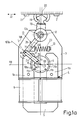
- FIG. 1a shows a single-phase synchronous motor 4 arranged on a mounting plate 3.
- This single-phase synchronous motor has a U-shaped stator iron 5 with two legs 5a and 5b. Excitation coils 6 connected in series are pushed onto the parallel legs. The free ends of the legs 5a and 5b are designed as stator poles 7.
- a two-pole, permanently magnetic rotor 9 is rotatably mounted about an axis 10.
- the rotor is preferably extrusion-coated with plastic, with the crank pin 18a also being molded on.
- the direction of magnetization of the rotor 9 is indicated by means of an arrow line 11.
- the contour 105a or 105b of the legs 5a and 5b in the region of the air gap 8 is symmetrical to the center line 110, that is to say deviates from the conventional single-phase synchronous motors and has no asymmetry.
- a double-armed lever 13 with a first lever arm 14 and a second lever arm 15 is mounted on the mounting plate 3 around a bearing eye 12.
- the free end of the first lever arm 14 has a push rod joint 16, on which a connecting rod 17 engages with one end 17a.
- the other end 17b of the connecting rod 17 is mounted on a crank pin 18 a of the rotor 9 by means of a crank pin joint 18.
- the second lever arm 15 is gripped by claws 19 of a lower knife 20 of a dry shaving device.
- the lower knife 20 is mounted by means of bearings 21 in such a way that it can execute reciprocating movements in the direction of a double arrow 22.
- first lever arm 14 engages a compression spring 23 which urges the first lever arm 14 when the single-phase synchronous motor 4 is not energized into a position in which the extension of the connecting line 24 between the push rod joint 16 and the crank pin 18a approximately by the Rotor axis 10 runs through.
- the drive In this position, the drive is in a first dead center position, in which the connecting rod is maximally deflected.
- the rotor At this first dead center position, the rotor is in a position in which its central magnetization direction, which is indicated by arrow 11, is perpendicular to the stator field direction, which is indicated by arrow 100, and approximately parallel to the center line 110.
- the rotor 9 of the single-phase synchronous motor 4 oscillates or swings back and forth, the central direction of magnetization of the rotor twisting to the left and right from one arrowhead 11a to the other arrowhead 11b.
- the compression spring 23 is so strong that the rotor 9 can not perform any orbital movement.
- the spring 23 can be a metal, plastic or rubber spring; the latter leads to a stronger damping of the drive.
- a rubber spring can limit the vibration amplitude of the rotor 9 when the mains voltage is high.
- the spring characteristic is preferably progressive.
- the lever mechanism made of double-armed lever 13 and connecting rod 17 is designed such that in the rest position of the rotor 9, the extension of the connecting line 24 between the push rod joint 16 and the crank pin 18a runs through the rotor axis 10, while at the same time a tangent 107a to the circular arc Movement line 106, which the push rod joint 16 executes about the rocker arm bearing 12a during the rocking movement, runs through the rotor axis 10.
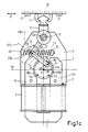
- Fig. 1b corresponds to the embodiment of Fig. 1a with the difference that the lever gear geometry is changed such that the oscillating movement of the lever 13 is thereby further symmetrized.
- the structure is selected such that the tangent 107b to the circular arc-shaped movement line 106b, which the push rod joint 16 executes about the rocker arm bearing 12a during the rocking movement, runs through the rotor axis 10 when the rocker arm 13 is in the middle position during nominal operation.
- Fig. 1c describes a further variant of the articulation of the connecting rod 17 on the rotor 9. It is provided that in the rest position of the rotor 9, the connecting line 24 of the push rod joint 16 with the crank pin 18a and the connecting line 24a of the crank pin 18a with the rotor axis 10 form an angle o include approximately 90, wherein the tangent runs 107c to the line of movement of the push rod 106c joint 16 in this position may be approximated by the crank pin 18a.
- the spring must also be designed so that it brings the rotor into the position in which its magnetization direction is perpendicular to the central stator field direction. This can be achieved, for example, with the aid of spring means 23, 23c mounted on the right and left of the first lever arm 14, which are supported on bearings 33 of the fastening plate 3.
- FIG. 2a shows another embodiment of a vibration drive for a household vibration device, which is modified compared to that according to FIGS. 1a to 1c.
- the drive contains two double-armed levers 13a and 13b with first lever arms 14a and 14b and second lever arms 15a and 15b.
- the lever arms 14a and 14b are articulated via connecting rod joints 16 and connecting rods 17a and 17b via crank pin joints 18 to crank pins 18a of the rotor 9.
- the extensions of the connecting lines 24 between the push rod joints 16 and the crank pin joints 18 of the two transmission lever halves according to FIG. 2a run through the rotor axis 10.
- the spring 23a is supported on bearing points 26 of the two lever arms 14a and 14b and thus between the arms 14a, 14b.
- the arm 14a belongs to a double-armed lever 13a with a lever arm 15a.
- the arm 14b belongs to a double-armed lever 13b with a lever arm 15b.
- the lever arm 15a acts on the lower knife 20, while the lever arm 15b is coupled to a counter-oscillating mass 20a, which is supported on arms 28 of the mounting plate 3 via damping springs 27.
- the levers 13a and 13b are mounted on the bearing eye 12.
- the vibrations of the device which are already relatively low, can be reduced even further.
- the damping springs 27 between the arms 28 of the mounting plate 3 cause further damping.
- the arrangement is such that in the rest position of the rotor 9 both connecting rods are maximally deflected and the rocker arms 13a, 13b are in opposite dead center positions that both rocker arms 13a, 13b have the same rocking motion, but in opposite directions to lead. It also applies that when the rotor 9 is at rest, the tangents 107d to the movement lines 106d of the two first lever arms 14a, 14b and the extensions of the connecting lines 24 of the associated push rod joints 16 and crank pin 18a run through the rotor axis 10 in the maximally deflected state and the arrangement in The idle state of the rotor 9 is symmetrical to the center line of the system.
- the embodiment according to FIG. 2b corresponds to the embodiment according to FIG. 2a with the exception of the articulation of the connecting rods 17a, 17b to the crank pin 18a of the rotor 9.
- the connecting rods 17a, 17b are articulated in this case in such a way that in the rest position of the rotor 9 both connecting rods 17a, 17b and the rocker arms 13a, 13b are in the nominal central position and that in the idle state of the rotor 9 the tangents 107e to the line of motion 106e of the first two lever arms 14a, 14b run through the crank pins 18a.
- the spring means consist of three springs 23a, 23d and 23e.
- the two outer springs 23d and 23e are supported on bearings 33 of the fastening plate and a respective first lever arm 14a and 14b.
- the third spring 23a is supported between the first lever arms 14a, 14b at the bearing points 26 of the lever arms.
- the connecting lines 24 of the associated push rod joints 16 and crank pin 18a and the connecting lines 24a of the crank pin 18a with the rotor axis 10 form an angle of approximately 90 ° .
- FIG. 3 the connecting rod 17.3 compared to the connecting rod 17 of Fig. 1a to 1c and adapted to the first lever arm 14.3 modified.
- the connecting rod 17.3 consists of a plastic part which engages with a crank pin joint 18, 3 on the crank pin 18 b.
- Crank pin 18b and crank pin joint 18.3 are offset diametrically from the corresponding parts according to FIG. 1. This reverses the knife end position in the rotor rest position.
- the plastic connecting rod 17.3 is guided in an arc 31 around the rotor axis 10.
- the connecting rod 17.3 is fixed on the first lever arm 14.3 by means of a plug-in connection 32.
- the connecting rod 17.3 is designed to be length-elastic and thus shock-absorbing. Further advantages of this construction can be seen in the fact that the movement reversal proceeds more evenly and without impulsive peak loads.
- a connecting rod is omitted in the embodiment according to FIG. 4a.
- the first lever arm 14, 4 is provided with a longitudinal slot 34a, in which the crank pin 18a engages.
- the magnetization direction in the rest position of the rotor 9 runs in the direction of the arrow 11, 4.
- the rotor is in a rest position, in which the crank pin 18a is approximately in the middle of the slot 34a.
- the arrangement is such that in the rest position of the rotor 9, the line 24b of the eccentric pin 18a with the rotor axis 10 and the line 24c of the rotor axis 10 with the rocker arm bearing 12 form a right angle.
- the rocker arm 13 to 13.4 can also be mounted as part of a modification of the drive mechanism in a torsion rubber element, the outer fastening ring of which is firmly connected to the rocker arm 13 to 13.4 and the inner fastening ring of which is fixed to the bearing eye 12.
- FIG. 4b corresponds to the embodiment according to FIG. 4a with the modification that in the rest position of the rotor 9 the line 24d between the rotor axis 10 and the rocker arm bearing 12a runs through the eccentric pin 18a. This is a version without frequency doubling.
- FIG. 4c An even simpler embodiment is described in FIG. 4c.
- the eccentric pin 18a does not move in a slot of the first lever arm 14.4.
- the change in distance between the rocker arm bearing 12a and the eccentric pin 18a that occurs during the oscillating movement is made possible in that the first lever arm 14, 4 is designed to be length-elastic.
- the line 24d runs through the rocker arm bearing 12a and the rotor axis 10 through the eccentric pin.
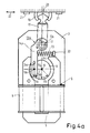
- FIG. 5 shows an embodiment of the drive of a vibration device in which the rocker arm bearing 12a, 5 is replaced by a cruciate ligament joint 35 the ligaments 36.
- the bearing eye 12, 5 is partly elongated partly cylindrical and is encompassed by a fastening ring 37 of the cruciate ligament joint 35.
- the cruciate ligaments 36 engage on this fastening ring 37 with first ends 38a.
- the other ends 38b of the cruciate ligaments engage the first lever arm 14.5.
- the second lever arm 15.5 of the rocking lever 13.5 takes the lower knife 20 with it and guides it along under the shaving foil 39 clamped in a shaving head 38.
- the bearing eye 12.5 is fixed on the mounting plate 3.5 via a bracket 40.
- the rocker arm 13.5 with the first lever arm 14.5 and the second lever arm 15.5 and the fastening ring 37 is injection-molded in one piece with the cruciate ligaments 36 from plastic. With this construction, the rocker arm bearing 12a, 5 results in the region of the cruciate ligaments 36. In addition, it is possible to adapt the rocker arm structure even more to the conditions with a necessary or desirable construction.
- the first lever arm 14, 5 is a first leg of a geometric figure, in particular a triangle or trapezoid, with the swing joint 35 designed as a cruciate ligament joint in the converging region of the first and second legs 14, 5, 14, which enclose an angle with one another. 5a.
- the compression spring 23 presses against the second leg 14, 5a and can be set in pressure by means of an adjustable clamp 41.
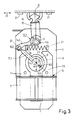
- Fig. 6 shows the drive of FIG. 5 in a side view, partially in section.
- the cut is so complicated that it was not shown in Fig. 5.
- the cut should clarify the structure and interaction of drive parts and bearings.
- the rotor 9 of the single-phase synchronous motor 4 is mounted with its axis 10 in slide bearings 41.
- the permanent magnetic rotor 9 is provided with a plastic encapsulation 42, to which the crank pin 18a is injection molded.
- Crank pin 18a and bearing shell 43 on the connecting rod 17 together form the crank pin joint 18 on the rotor.
- the push rod joint 16 is formed by an axle stub 44 at the end 17a of the connecting rod 17 and an associated bearing shell 45 on the first lever arm 14.5.
- the ends of the first lever arm 14, 5 and the cruciate ligaments 36 act on the opposite side of the parallelogram 14, 5b with their ends 38b.
- the second lever arm 15.5 has a bore which allows it to move freely around the bearing eye 12.5 which is designed as a pin in this area.
- the fastening rings 37 of the cruciate ligament joint 35 firmly enclose the bearing eye 12.5.
- the drive mechanism and the motor are fixed in the mounting plate 3, 5, and this is in turn located between the narrow side walls 46, 47 of the device housing.
- the rocker arm 13, 7 again has the cruciate ligaments 36 already shown in FIGS. 5 and 6 in the area of the cruciate ligament joint 35. These cruciate ligaments 36, crossing one another, extend from the lever arm side 14, 7b to an insertion holder 48 on a bridge 49.
- the rocker arm 13.7 with the cruciate ligaments 36 and the bracket 48 are in one piece injected from plastic, the plastic must guarantee the elasticity of the universal joint ligaments in the region of the universal joint 35.
- the holder 48 is inserted into a plastic bridge 49, which in turn is screwed with its ends 49a and 49b to the mounting plate 3, 7 or otherwise fixed.
- a simple type of electronic control is a two-way rectified AC voltage, which is shown in Fig. 8.
- An AC mains voltage with a frequency of 50 Hz or 60 Hz is applied to the terminals 110.
- a full-wave rectifier 111 rectifies the mains AC voltage and forms a DC voltage of double frequency, ie 110 Hz or 120 Hz, indicated by the symbol 112, which is applied to the stator coils 5a, 5b.
- the oscillation frequency is doubled in this way.
Abstract
Description
Die Erfindung bezieht sich auf ein Haushaltsvibrationsgerät, insbesondere Trockenrasier- oder Haarschneidegerät, bei dem Bewegungen eines als Rotor ausgebildeten zweipoligen Permanentmagneten in einer durch Spulen erregten Statoranordnung eine Vibrationsbewegung eines Vibrationswerkzeuges erzeugen, und zwar über ein Hebelsysstem, das an die Bewegungen des Rotors gekoppelt ist, wobei eine auf das Hebelsystem einwirkende rückstellende Federkraft den aus Hebelsystem und Rotor bestehenden Antrieb so vorspannt, daß der Rotor Pendelbewegungen um eine Ruhelage ausführen kann,
wobei das Hebelsystem einen doppelarmigen Schwinghebel aufweist und
wobei das Hebelsystem mit einem exzentrisch angeordneten Zapfen des Rotors verbunden ist.The invention relates to a household vibration device, in particular a dry shaving or hair cutting device, in which movements of a two-pole permanent magnet designed as a rotor in a stator arrangement excited by coils generate a vibration movement of a vibration tool, specifically via a lever system which is coupled to the movements of the rotor. a resilient spring force acting on the lever system prestressing the drive consisting of the lever system and the rotor so that the rotor can perform oscillating movements around a rest position,
wherein the lever system has a double-arm rocker arm and
wherein the lever system is connected to an eccentrically arranged pin of the rotor.
Ein derartiges Haushaltsvibrationsgerät in Form eines Trockenrasier- bzw. Haarschneidegerätes ist aus der DE-PS 34 04 297 bekannt. Es kommt dabei ein Einphasen-Synchronmotor mit zweipoligem, dauermagnetischem Rotor zum Einsatz. Für den Betrieb eines Einphasen-Synchronmotors in Verbindung mit einem Vibrationswerkzeug sind besondere Dimensionierungen und konstruktive Maßnahmen erforderlich, um einen sicheren Anlauf und die Stabilität der Bewegung zu gewährleisten. Die Umwandlung der umlaufenden Bewegungen des Rotors in eine Schwingbewegung doppelter Frequenz des Werkzeuges, nämlich eines Untermessers, erfolgt dabei mittels eines Rollen-Nockengetriebes. Auf das Rollen-Nockengetriebe wirkt eine Feder ein, die einerseits der Anlaufunterstützung dient und andererseits dafür sorgt, daß die Rolle nicht von dem Nocken abhebt.Such a household vibration device in the form of a dry shaving or hair cutting device is known from DE-PS 34 04 297. A single-phase synchronous motor with a two-pole, permanent-magnet rotor is used. For the operation of a single-phase synchronous motor in connection with a vibrating tool, special dimensions and constructive measures are necessary to ensure a safe start and the stability of the movement. The conversion of the rotating movements of the rotor into an oscillating movement of twice the frequency of the tool, namely a lower knife, is carried out by means of a roller cam gear. A spring acts on the roller cam gear, which serves on the one hand to support starting and on the other hand ensures that the roller does not lift off the cam.
Der Vorteil eines solchen Antriebes besteht in den geringen Raumanforderungen. Ein Einphasen-Synchronmotor ist kleiner als ein Schwingankermotor gleicher Leistung. Die den Anlauf und die Laufstabilität gewährleistenden Maßnahmen erfordern aber die Einhaltung bestimmter enger Toleranzen im Bereich des Umlenkgetriebes und der Motorauslegung. Des weiteren hat das Rollen-Nockengetriebe große mechanische Umsetzungsverluste an der Berührungsfläche von Rolle und Nocken.The advantage of such a drive is the small space requirements. A single-phase synchronous motor is smaller than an oscillating armature motor of the same power. The measures ensuring the start-up and the running stability, however, require compliance with certain narrow tolerances in the area of the reversing gear and the motor design. Furthermore, the roller cam gear has large mechanical implementation losses at the contact surface of the roller and cam.
Aus der US-PS 33 33 172 ist eine Zeitmeßvorrichtung mit einer Unruhefeder einer Uhr bekannt. Die spiralförmige Unruhefeder begrenzt die Bewegungen des Rotors; sie schwingt im wesentlichen mit einer Frequenz, die von der Masse und Federkonstruktion des Systems abhängt. Die Spulenansteuerung erfolgt elektronisch. Der Motor ist nach Art eines Einphasen-Synchronmotors ausgebildet; er ist jedoch nicht als Leistungsantrieb einer Kraftmaschine gedacht oder verwendbar. Der Luftspalt ist symmetrisch zur Mittellinie durch die Statorbohrung parallel zur Statorfeldrichtung.From US-
Aus der DE-OS 20 32 520 ist ein Schwingankermotor bekannt, der zum Antreiben einer Haarschneidemaschine dient und der ein von Wechselstrom erregtes Magnetsystem aufweist, dessen von seinen Wechselpolen schwingbetätigter Anker einen Dauermagneten enthält, der zusammen mit seinen Polschuhen im wesentlichen um seine Mittelachse hinaus herschwingt. Ein Anker mit Polschuhen ist aufwendig und hat eine große Schwingmasse. Der beschriebene Stator ist ebenfalls kompliziert aufgebaut. Der Anker trägt einen exzentrischen Zapfen, der in einen mit einem bewegbaren Untermesser verbundenen zweiarmigen Hebel eingreift. Weil in der Mittelstellung des Hebels die Verbndungslinie von Ankerwelle und Schwinghebel durch den exzentrischen Zapfen verläuft, sind die Schwingfrequenz des Ankers und des bewegbaren Messers einander gleich. Bei dem vorgesehenen Betrieb an einem 50 Hz-Netz ist die Schwingfrequenz 50 Hz.From DE-OS 20 32 520 an oscillating armature motor is known which serves to drive a hair clipper and which has a magnet system excited by alternating current, the armature of which is actuated by its alternating poles and contains a permanent magnet which, together with its pole pieces, oscillates essentially around its central axis . An anchor with pole pieces is complex and has a large vibration mass. The stator described is also of complex construction. The armature carries an eccentric pin which engages in a two-armed lever connected to a movable lower knife. Because in the middle position of the lever, the connecting line of the armature shaft and rocker arm through the eccentric pin runs, the oscillation frequency of the armature and the movable knife are equal to each other. When operating on a 50 Hz network, the oscillation frequency is 50 Hz.
Es ist Aufgabe der Erfindung, ein Haushaltsvibrationsgerät der eingangs erwähnten Art zu schaffen, das in vorteilhafter Weise von einem Motor nach Art eines Einphasen-Synchronmotors angetrieben wird, bei dem aber Maßnahmen zur Anlaufverbesserung und zur Verbesserung des dynamischen Verhaltens überflüssig und die mechanischen Umsetzungsverluste gering sind.It is an object of the invention to provide a household vibration device of the type mentioned at the outset which is advantageously driven by a motor in the manner of a single-phase synchronous motor, but in which measures for improving the start-up and for improving the dynamic behavior are superfluous and the mechanical implementation losses are low .
Die gestellte Aufgabe ist erfindungsgemäß gelöst durch mehrere Ausführungsformen. Eine erste Ausführungsform ist dadurch gekennzeichnet, daß
- der zweipolige, permanentmagnetische und polschuhlose Rotor in dem U-förmigen Stator eines Einphasensynchronmotors angeordnet ist,
- ein erster Hebelarm des doppelarmigen Schwinghebels und der Rotor über eine Pleuelstange verbunden sind, die mittels eines Schubstangengelenkes am ersten Hebelarm einerseits und exzentrisch mittels des Kurbelzapfens am Rotor andererseits gelenkig angreift,
- die Federkraft den Antrieb so vorspannt, daß die Ruhelage des Rotors bei abgeschalteten Statorspulen zusammenfällt mit der Position, in der die mittlere Magnetisierungsrichtung des Rotors näherungsweise senkrecht auf der mittleren Magnetfeldrichtung der Statoranordnung steht,
- in der Ruhestellung des Rotors die Verlängerung der Verbindungslinie zwischen dem Schubstangengelenk und dem Kurbelzapfen durch die Rotorachse verläuft, wodurch die mechanische Schwingfrequenz des Schwinghebels gegenüber der des Rotors verdoppelt ist.The object is achieved according to the invention by several embodiments. A first embodiment is characterized in that
the two-pole, permanent magnetic and pole shoe-free rotor is arranged in the U-shaped stator of a single-phase synchronous motor,
a first lever arm of the double-armed rocker arm and the rotor are connected via a connecting rod which, on the one hand, articulates by means of a push rod joint on the first lever arm and eccentrically by means of the crank pin on the rotor,
the spring force prestresses the drive such that the rest position of the rotor when the stator coils are switched off coincides with the position in which the central direction of magnetization of the rotor is approximately perpendicular to the central direction of the magnetic field of the stator arrangement,
- In the rest position of the rotor, the extension of the connecting line between the push rod joint and the crank pin extends through the rotor axis, as a result of which the mechanical oscillation frequency of the oscillating lever is doubled compared to that of the rotor.
Eine zweite Ausführungsform ist dadurch gekennzeichnet, daß
- der zweipolige, permanentmagnetische und polschuhlose Rotor in dem U-förmigen Stator eines Einphasensynchronmotors angeordnet ist,
- der erste Hebelarm als Schlitzumformer ausgebildet ist mit einem Längsschlitz, in den ein Exzenterzapfen des Rotors eingreift,
- in der Ruhelage des Rotors die Verbindungslinie des Exzenterzapfens mit der Rotorachse und die Verbindungslinie der Rotorachse mit dem Schwinghebellager einen rechten Winkel bilden,
- die Federkraft den Antrieb so vorspannt, daß die Ruhelage des als Rotor ausgebildeten Permanentmagneten bei abgeschalteten Statorspulen zusammenfällt mit der Position, in der die mittlere Magnetisierungsrichtung des Rotors näherungsweise senkrecht auf der mittleren Magnetfeldrichtung der Statoranordnung steht, wodurch die mechanische Schwingfrequenz des Schwinghebels gegenüber der Schwingfrequenz des Rotors verdoppelt wird.A second embodiment is characterized in that
the two-pole, permanent magnetic and pole shoe-free rotor is arranged in the U-shaped stator of a single-phase synchronous motor,
the first lever arm is designed as a slot converter with a longitudinal slot into which an eccentric pin of the rotor engages,
- In the rest position of the rotor, the connecting line of the eccentric pin with the rotor axis and the connecting line of the rotor axis with the rocker arm bearing form a right angle,
- The spring force biases the drive so that the rest position of the permanent magnet designed as a rotor coincides with the stator coils switched off, with the position in which the central direction of magnetization of the rotor is approximately perpendicular to the central direction of the magnetic field of the stator arrangement, as a result of which the mechanical oscillation frequency of the oscillating lever is compared to the oscillation frequency of the rotor is doubled.
Eine dritte Ausführungsform ist dadurch gekennzeichnet, daß
- der zweipolige, permanentmagnetische und polschuhlose Rotor in dem U-förmigen Stator eines Einphasensynchronmotors angeordnet ist,
- ein erster Hebelarm des doppelarmigen Schwinghebels und der Permanentmagnetrotor über eine Pleuelstange verbunden sind, die mittels eines Schubstangengelenkes am ersten Hebelarm einerseits und exzentrisch mittels des Kurbelzapfens am Rotor andererseits gelenkig angreift,
- die Federkraft den Antrieb so vorspannt, daß die Ruhelage des Rotors bei abgeschalteten Statorspulen zusammenfällt mit der Position, in der die mittlere Magnetisierungsrichtung des Rotors näherungsweise senkrecht auf der mittleren Magnetfeldrichtung der Statoranordnung steht,
- in der Ruhelage des Rotors die Verbindungslinie des Schubstangengelenkes mit dem Kurbelzapfen und die Verbindungslinie des Kurbelzapfens mit der Rotorachse einen Winkel von annähernd 90o einschließen,
- die Tangente an die Bewegungslinie des Schubstangengelenkes in dieser Stellung näherungsweise durch den Kurbelzapfen verläuft,
- die Ruhelage des Rotors durch beidseitig des ersten Hebelarmes angebrachter Federmittel, die in Lagern der Befestigungsplatte gelagert sind, eingestellt wird, wodurch die Schwingfrequenz des Schwinghebels und des Rotors gleich sind,
- die gewünschte Schwingfrequenz des Schwinghebels durch die elektrische Ansteuerung der Spulen bestimmt wird.A third embodiment is characterized in that
the two-pole, permanent magnetic and pole shoe-free rotor is arranged in the U-shaped stator of a single-phase synchronous motor,
a first lever arm of the double-arm rocking lever and the permanent magnet rotor are connected via a connecting rod which, on the one hand, articulates by means of a push rod joint on the first lever arm and eccentrically by means of the crank pin on the rotor,
- The spring force biases the drive so that the rest position of the rotor when the stator coils are switched off coincides with the position in which the central direction of magnetization of the rotor is approximately perpendicular to the central direction of the magnetic field of the stator arrangement,
in the rest position of the rotor, the connecting line of the push rod joint with the crank pin and the connecting line of the crank pin with the rotor axis enclose an angle of approximately 90 ° ,
in this position the tangent to the line of movement of the push rod joint runs approximately through the crank pin,
the rest position of the rotor is adjusted by spring means attached on both sides of the first lever arm, which are mounted in bearings in the mounting plate, as a result of which the oscillation frequency of the oscillating lever and the rotor are the same,
- The desired vibration frequency of the rocker arm is determined by the electrical control of the coils.
Eine vierte Ausführungsform ist dadurch gekennzeichnet, daß
- der zweipolige, permanentmagnetische und polschuhlose Rotor in dem U-förmigen Stator eines Einphasensynchronmotors angeordnet ist,
- der erste Hebelarm als Schlitzumformer ausgebildet ist mit einem Längsschlitz, in den ein Exzenterzapfen des Rotors eingreift,
- in der Ruhelage des Rotors die Verbindungslinie zwischen der Rotorachse und dem Schwinghebellager durch den Exzenterzapfen verläuft,
- die Federkraft den Antrieb so vorspannt, daß die Ruhelage des Rotors bei abgeschalteten Statorspulen zusammenfällt mit der Position, in der die mittlere Magnetisierungsrichtung des Rotors näherungsweise senkrecht auf der mittleren Magnetfeldrichtung der Statoranordnung steht, wodurch die mechanische Schwingfrequenz des Schwinghebels gegenüber dem Rotor gleich ist,
- die gewünschte Schwingfrequenz des Schwinghebels durch die elektrische Ansteuerung der Spulen bestimmt wird.A fourth embodiment is characterized in that
the two-pole, permanent magnetic and pole shoe-free rotor is arranged in the U-shaped stator of a single-phase synchronous motor,
the first lever arm is designed as a slot converter with a longitudinal slot into which an eccentric pin of the rotor engages,
- In the rest position of the rotor, the connecting line between the rotor axis and the rocker arm bearing runs through the eccentric pin,
- The spring force biases the drive so that the rest position of the rotor when the stator coils are switched off coincides with the position in which the mean direction of magnetization of the rotor approximately is perpendicular to the central magnetic field direction of the stator arrangement, as a result of which the mechanical oscillation frequency of the oscillating lever is the same with respect to the rotor
- The desired vibration frequency of the rocker arm is determined by the electrical control of the coils.
Der Antrieb eines derartigen Haushaltsvibrationsgerätes weist einen guten Wirkungsgrad auf, weil keine mechanischen Kontaktflächenverluste wie beim Rollen-Nockengetriebe auftreten, weshalb er auch besonders geeignet ist für einen Batteriebetrieb. Es kann weiterhin der bekannte und vorteilhafte Einphasensynchronmotor eingezeigt werden, der wirtschaftlich zu fertigen ist und eine besonders flache Bauweise hat. Die Anlaufschwierigkeiten sind reduziert, weil die Parallelstellung von Rotorfeld und Statorfeld nicht mehr auftreten kann und das dynamische Verhalten unproblematisch ist. Der Antrieb weist ein angenehmes Laufgeräusch auf. Der einfache Aufbau des Schwingantriebes wird mit bekannten Konstruktionskomponenten erreicht.The drive of such a household vibration device has a good efficiency because there are no mechanical contact surface losses as with the roller cam gear, which is why it is also particularly suitable for battery operation. The known and advantageous single-phase synchronous motor can also be shown, which is economical to manufacture and has a particularly flat design. The starting difficulties are reduced because the parallel position of the rotor field and stator field can no longer occur and the dynamic behavior is unproblematic. The drive has a pleasant running noise. The simple construction of the vibratory drive is achieved with known construction components.
Nach einer Weiterbildung der ersten Ausführungsform der Erfindung ist vorgesehen, daß
- gleichzeitig die Tangente an die kreisbogenförmige Bewegungslinie, die das Schubstangengelenk um das Schwinghebellager bei der Schwingbewegung ausführt, durch die Rotorachse verläuft.According to a development of the first embodiment of the invention, it is provided that
- At the same time, the tangent to the arcuate line of motion that the push rod joint executes about the rocker arm bearing during the rocking movement runs through the rotor axis.
Hierdurch wird festgelegt, daß die eine Totpunktlage des Werkzeuges zusammenfällt mit der Ruhelage des Rotors, um die herum der Rotor Schwingungen ausführt. Die Schwingbewegung des Hebelarms hat hier die doppelte Grundfrequenz der Schwingbewegung des Rotors, deren Grundfrequenz gleich der Frequenz der angelegten Spannung ist. Dies ist besonders vorteilhaft bei Vibrationstrockenrasiergeräten, bei denen eine Schwingfrequenz von 100 Hz bzw. 120 Hz gebräuchlich ist.This determines that the dead center position of the tool coincides with the rest position of the rotor, around which the rotor carries out vibrations. The swinging movement of the lever arm has twice the basic frequency the oscillating movement of the rotor, the fundamental frequency of which is equal to the frequency of the applied voltage. This is particularly advantageous in the case of vibration dry shavers in which an oscillation frequency of 100 Hz or 120 Hz is common.
Ausgehend von der Totpunktlage hängen die Amplitude der Schwingbewegung des Werkzeuges und damit auch dessen Mittelstellung ab von der Schwingbewegung des Rotors, die wiederum durch sämtliche Systemparameter, wie Spannung, Reibung, Federdaten usw., bestimmt wird. Die Mittelstellung ändert sich demnach mit den Betriebsdaten. Ebenfalls ist bei festliegender erster Totpunktlage die zweite Totpunktlage des Werkzeuges von den Betriebsverhältnissen abhängig. Für Nennbetrieb mit Nenndaten läßt sich jedoch eine Nennmittelstellung definieren. In dieser verläuft z. B. die Verbindungslinie des Werkzeugmittelpunktes mit dem Schwinghebellager des zweiarmigen Hebels durch die Rotorachse.Starting from the dead center position, the amplitude of the oscillating movement of the tool and thus also its center position depend on the oscillating movement of the rotor, which in turn is determined by all system parameters, such as tension, friction, spring data, etc. The middle position therefore changes with the operating data. With the first dead center position fixed, the second dead center position of the tool is also dependent on the operating conditions. However, a nominal middle position can be defined for nominal operation with nominal data. In this z. B. the connecting line of the tool center with the rocker arm bearing of the two-armed lever through the rotor axis.
Wenn die Tangente an die Bewegungslinie des ersten Hebelarms bei maximaler Auslenkung des Hebels durch die Rotorachse verläuft, erhält man ein besonders einfach zu konstruierendes Gerät mit einer noch befriedigend symmetrischen Schwinghebelbewegung. Die mechanische Konstruktion geht hierbei bei zunächst vorgegebenen Rotorschwingwinkel und Werkzeugschwingweg aus von der Länge des ersten Hebelarms sowie der Länge des Pleuelarms und dem Abstand des Kurbelzapfens von der Rotorachse.If the tangent to the line of movement of the first lever arm runs through the rotor axis with maximum deflection of the lever, a particularly easy-to-construct device with a still satisfactorily symmetrical rocking lever movement is obtained. The mechanical design is based on the length of the first lever arm as well as the length of the connecting rod arm and the distance of the crank pin from the rotor axis, given the initially predetermined rotor swing angle and tool swing path.
In einer speziellen Ausgestaltung der ersten Ausführung der Erfindung ist vorgesehen, daß die Summe aus der Länge der Pleuelstange und dem Abstand des Kurbelzapfens von der Rotorachse gleich der Länge des ersten Hebelarms ist und daß bei maximaler Auslenkung die Verbindungslinie des Schwinghebellagers mit dem Schubstangengelenk und die auf einer Linie liegenden Verbindungslinien von Schubstangengelenk und Kurbelzapfen und Kurbelzapfen und Rotorachse einen rechten Winkel bilden. Hierdurch läßt sich eine besonders handliche und kompakte Formgebung realisieren.In a special embodiment of the first embodiment of the invention it is provided that the sum of the length of the connecting rod and the distance of the crank pin from the rotor axis is equal to the length of the first lever arm and that the connecting line of the The rocker arm bearing with the push rod joint and the connecting lines of the push rod joint and crank pin and crank pin and rotor axis lying in a line form a right angle. This enables a particularly handy and compact shape to be achieved.
Der Verlauf der Schwingbewegung des Hebels und des Werkzeuges hängt außer von der Schwingbewegung des Rotors ab von der Bewegungslinie, die das Schubstangengelenk aufgrund der mechanischen Konstruktion durchführt.The course of the swinging movement of the lever and the tool depends not only on the swinging movement of the rotor, but also on the movement line which the push rod joint performs due to the mechanical construction.
Nach einer weiteren Ausgestaltung der ersten Ausführungsform der Erfindung ist vorgesehen, daß
die Tangente an die kreisbogenförmige Bewegungslinie, die das Schubstangengelenk um das Schwinghebellager bei der Schwingbewegung ausführt, durch die Rotorachse verläuft, wenn sich der Schwinghebel bei Nennbetrieb in Mittelstellung befindet.According to a further embodiment of the first embodiment of the invention, it is provided that
the tangent to the circular arc-shaped movement line, which the push rod joint executes around the rocker arm bearing during the rocking movement, runs through the rotor axis when the rocker arm is in the middle position during nominal operation.
Wenn die Tangente an die Bewegungslinie in der Nennmittelstellung durch die Rotorachse verläuft, erhält man eine besonders symmetrische Bewegung des Schwinghebels mit gleichen Amplituden beim Vor- und Zurückschwingen des Rotors.If the tangent to the line of movement in the nominal center position runs through the rotor axis, a particularly symmetrical movement of the rocker arm is obtained with the same amplitudes when the rotor swings back and forth.
Eine weitere vorteilhafte Ausgestaltung der ersten Ausführungsform des schwingenden Systems läßt sich dadurch erreichen, daß die Pleuelstange aus Kunststoff besteht, wobei das Schubstangengelenk als Filmscharnier ausgebildet ist. Durch den Ersatz des Schubstangengelenkes durch ein Filmscharnier wird der konstruktive Aufbau wesentlich vereinfacht. Wenn nach einer weiteren Ausgestaltung der ersten Ausführungsform die Pleuelstange längenelastisch ausgebildet ist, dann läßt sich durch diese als Dämpfer wirkende Konstruktion die Bewegung des Systems verbessern. Spitzenbelastungen werden ausgeglichen.A further advantageous embodiment of the first embodiment of the oscillating system can be achieved in that the connecting rod is made of plastic, the connecting rod joint being designed as a film hinge. By replacing the push rod joint with a film hinge, the construction is considerably simplified. If according to a further embodiment of the first embodiment, the connecting rod is designed to be length-elastic, then the construction of the system acting as a damper can improve the movement of the system. Peak loads are balanced.
Nach einer weiteren Ausgestaltung der ersten Ausführungsform der Erfindung ist vorgesehen, daß
- zusätzlich zu dem ersten zweiteiligen Schwinghebel auf dem gleichen Schwinghebellager unabhängig davon ein zweiter zweiteiliger Schwinghebel mit einem ersten und einem zweiten Hebelarm gelagert ist, wobei die beiden ersten Hebelarme über Schubstangengelenke, Pleuelstangen und Kurbelzapfengelenke am Rotor angreifen, wobei in Ruhelage des Rotors beide Pleuelstangen maximal ausgelenkt sind und die Schwinghebel sich in gegenüberliegenden Totpunktlagen befinden,
- beide Schwinghebel die gleichen Schwingbewegungen, jedoch gegenläufig ausführen, wobei zwischen den beiden ersten Hebelarmen eine Druckfeder angebracht ist,
- einer der beiden zweiten Hebelarme das Werkzeug antreibt und an dem anderen der beiden zweiten Hebelarme eine gegenschwingende Masse angebracht ist, mit deren Hilfe eine Vibrationsdämpfung erreicht wird,
- im Ruhezustand des Rotors die Tangenten an die Bewegungslinien der beiden ersten Hebelarme und die Verlängerung der Verbindungslinien der zugehörigen Schubstangengelenke und Kurbelzapfen im maximal ausgelenkten Zustand durch die Rotorachse verlaufen und die Hebelanordnung im Ruhezustand des Rotors symmetrisch zur Mittellinie des Antriebes ist.According to a further embodiment of the first embodiment of the invention, it is provided that
- In addition to the first two-part rocker arm on the same rocker arm bearing, a second two-part rocker arm with a first and a second lever arm is mounted independently of it, the two first lever arms acting on the rotor via connecting rod joints, connecting rods and crank pin joints, with both connecting rods being at a maximum when the rotor is at rest are deflected and the rocker arms are in opposite dead center positions,
- Both rocker arms perform the same rocking movements, but in opposite directions, a compression spring being attached between the first two lever arms,
one of the two second lever arms drives the tool and a counter-oscillating mass is attached to the other of the two second lever arms, with the aid of which vibration damping is achieved,
- In the idle state of the rotor, the tangents to the lines of movement of the first two lever arms and the extension of the connecting lines of the associated push rod joints and crank pins run through the rotor axis in the maximally deflected state and the lever arrangement in the idle state of the rotor is symmetrical to the center line of the drive.
Auf diese Weise läßt sich ein besonders ruhiger und vibrationsfreier Betrieb erreichen.In this way, a particularly quiet and vibration-free operation can be achieved.
Bei einer Ausgestaltung der zweiten Ausführungsform der Erfindung ist es möglich, auf die Pleuelstange zu verzichten, wenn der Antrieb derart gebildet ist, daß der erste Hebelarm als Schlitzumformer ausgebildet ist mit einem Längsschlitz, in den ein Exzenterzapfen des Rotors eingreift.In one embodiment of the second embodiment of the invention, it is possible to dispense with the connecting rod if the drive is formed in such a way that the first lever arm is designed as a slot converter with a longitudinal slot into which an eccentric pin of the rotor engages.
Eine besonders einfache Konstruktion ergibt sich, wenn vorgesehen ist, daß der erste Hebelarm längenelastisch ausgebildet und ohne Längsschlitz oder dergleichen am Exzenterzapfen angreift. Durch die Längenelastizität wird in diesem Fall die bei der Bewegung des Schwinghebels erforderlich werdende Längenänderung zur Verfügung gestellt.A particularly simple construction results if it is provided that the first lever arm is of length-elastic design and acts on the eccentric pin without a longitudinal slot or the like. In this case, the length elasticity makes the length change required when the rocker arm moves.
Ein solcher Schlitzumformer arbeitet im wesentlichen wie ein Antrieb mit Pleuelstange, läßt sich aber einfacher verwirklichen und hat weniger Bauteile.Such a slot converter works essentially like a drive with a connecting rod, but is easier to implement and has fewer components.
Bei der dritten Ausführungsform der Erfindung befindet sich das Werkzeug ebenfalls in Mittelstellung, wenn sich der Rotor in der Ruhelage befindet. Bei der beschriebenen Konfiguration ergibt sich bei symmetrischer Schwingung des Rotors um seine Ruhelage eine symmetrische Schwingung des Werkzeuges um die oben definierte Mittelstellung mit gleich großen Schwingweiten nach rechts und links. Die Schwingweiten selbst sind von der Schwingweite des Rotors abhängig.In the third embodiment of the invention, the tool is also in the middle position when the rotor is in the rest position. In the configuration described, symmetrical oscillation of the rotor around its rest position results in symmetrical oscillation of the tool around the above-defined central position with equal oscillation distances to the right and left. The vibration ranges themselves depend on the vibration range of the rotor.
Die Grundwelle der Schwingung des Hebels hat hier die gleiche Frequenz wie die Schwingung des Rotors, die gleich der Frequenz der angelegten Spannung ist. Ein derartiger Aufbau ist günstig, wenn der beschriebene Antriebsmechanismus mit einem zweiteiligen Hebel und einer Pleuelstange z.B. aus Gründen der Standardisierung verwendet werden soll und wenn eine Frequenzverdopplung nicht erforderlich ist, z. B. wenn die Ansteuerfrequenz bereits 100 Hz beträgt oder wenn die Betriebsfrequenz für das Arbeiten des Gerätes ausreicht. Zu nennen sind für diesen Fall Tondeuse- oder Haarschneidegeräte.The fundamental wave of the vibration of the lever here has the same frequency as the vibration of the rotor, which is equal to the frequency of the applied voltage. Such a structure is favorable if the drive mechanism described with a two-part lever and a connecting rod, for example for reasons of standardization should be used and if frequency doubling is not required, e.g. B. if the control frequency is already 100 Hz or if the operating frequency is sufficient for the device to work. In this case, tondeuse or hair clippers are to be mentioned.
Nach einer weiteren Ausgestaltung der dritten Ausführung der Erfindung ist vorgesehen, daß
- zusätzlich zu dem ersten zweiteiligen Schwinghebel auf dem gleichen Schwinghebellager unabhängig davon ein zweiter zweiteiliger Schwinghebel mit einem ersten und einem zweiten Hebelarm gelagert ist, wobei die beiden ersten Hebelarme über Schubstangengelenke, Pleuelstangen und Kurbelzapfengelenke am Rotor angreifen, wobei in Ruhelage des Rotors beide Pleuelstangen und die Schwinghebel sich in der Nenn-Mittelstellung befinden,
- beide Hebel die gleiche Schwingbewegung, jedoch gegenläufig ausführen, wobei der Rotor durch auf die beiden ersten Hebelarme wirkende Federmittel in Ruhe in der Mittelstellung gehalten wird,
- einer der beiden zweiten Hebelarme das Werkzeug antreibt und an dem anderen der beiden zweiten Hebelarme eine gegenschwingende Masse angebracht ist, mit deren Hilfe eine Vibrationsdämpfung erreicht wird,
- im Ruhezustand des Rotors die Tangenten an die Bewegungslinien der beiden ersten Hebelarme durch die Kurbelzapfen verlaufen und die Verbindungslinien der zugehörigen Schubstangengelenke und Kurbelzapfen mit den Verbindungslinien der Kurbelzapfen mit der Rotorachse einen Winkel von etwa 90o bilden.According to a further embodiment of the third embodiment of the invention, it is provided that
- In addition to the first two-part rocker arm on the same rocker arm bearing, a second two-part rocker arm with a first and a second lever arm is mounted independently of it, the two first lever arms acting on the rotor via connecting rod joints, connecting rods and crank pin joints, with both connecting rods and in the rest position of the rotor the rocker arms are in the nominal middle position,
- Both levers perform the same oscillating movement, but in opposite directions, the rotor being held in the central position at rest by spring means acting on the first two lever arms,
one of the two second lever arms drives the tool and a counter-oscillating mass is attached to the other of the two second lever arms, with the aid of which vibration damping is achieved,
- extend in the rest condition of the rotor, the tangents to the lines of movement of the two first lever arms through the crank pins and the connecting lines of the associated push rod joints and crank pins with the connecting lines of the crank pin to the rotor axis form an angle of about 90 o.
In einer speziellen Ausführung ist vorgesehen, daß die gegenschwingende Masse, auf die eines der zweiten Hebelarme einwirkt, eine Tondeuse oder ein Zusatzgerät eines Rasiergerätes ist.In a special embodiment it is provided that the counter-oscillating mass, on which one of the second lever arms acts, is a tondeuse or an additional device of a shaving device.
Eine vorteilhafte Ausgestaltung der dritten Ausführungsform des schwingenden Systems läßt sich auch dadurch erreichen, daß die Pleuelstange aus Kunststoff besteht, wobei das Schubstangengelenk als Filmscharnier ausgebildet ist. Durch den Ersatz des Schubstangengelenkes durch ein Filmscharnier wird der konstruktive Aufbau wesentlich vereinfacht. Wenn nach einer weiteren Ausgestaltung der Erfindung vorgesehen ist, daß die Pleuelstange längenelastisch ausgebildet ist, dann läßt sich durch diese als Dämpfer wirkende Konstruktion die Bewegung des Systems verbessern. Spitzenbelastungen werden ausgeglichen.An advantageous embodiment of the third embodiment of the oscillating system can also be achieved in that the connecting rod is made of plastic, the push rod joint being designed as a film hinge. By replacing the push rod joint with a film hinge, the construction is considerably simplified. If, according to a further embodiment of the invention, it is provided that the connecting rod is designed to be length-elastic, the construction of the system acting as a damper can be improved. Peak loads are balanced.
Bei der vierten Ausführungsform der Erfindung ergibt sich eine besonders einfache Konstruktion, wenn vorgesehen ist, daß der erste Hebelarm längenelastisch ausgebildet und ohne Längsschlitz oder dergleichen am Exzenterzapfen angreift. Durch die Längenelastizität wird in diesem Fall die bei der Bewegung des Schwinghebels erforderlich werdende Längenänderung zur Verfügung gestellt.In the fourth embodiment of the invention, a particularly simple construction results if it is provided that the first lever arm is of length-elastic design and engages the eccentric pin without a longitudinal slot or the like. In this case, the length elasticity makes the length change required when the rocker arm moves.
Ein solcher Schlitzumformer arbeitet im wesentlichen wie ein Antrieb mit Pleuelstange, läßt sich aber einfacher verwirklichen und hat weniger Bauteile.Such a slot converter works essentially like a drive with a connecting rod, but is easier to implement and has fewer components.
Nach einer weiteren Ausgestaltung der Erfindung ist vorgesehen, daß der Rotor in einem Torsionsfederelement gelagert ist. Das Torsionsfederelement kann aus Gummi oder einem anderen elastischen Werkstoff bestehen und die sonst erforderliche Rotorwelle und das Rotorlager ersetzen.According to a further embodiment of the invention it is provided that the rotor is mounted in a torsion spring element. The torsion spring element can be made of rubber or another elastic material and can replace the rotor shaft and the rotor bearing that are otherwise required.
Die Lagerung von Schwinghebeln erfordert einen besonders stabilen und verschleißarmen Aufbau mit geringen Toleranzen, damit die Geräuschbildung in Grenzen gehalten werden kann.The storage of rocker arms requires a particularly stable and low-wear construction with low tolerances, so that the noise can be kept within limits.
Nach einer weiteren Ausgestaltung der Erfindung ist vorgesehen, daß der Rotor in einem Torsionsfederelement gelagert ist. Das Torsionsfederelement kann aus Gummi oder einem anderen elastischen Werkstoff bestehenund die sonst erforderliche Rotorwelle und das Rotorlager ersetzen.According to a further embodiment of the invention it is provided that the rotor is mounted in a torsion spring element. The torsion spring element can be made of rubber or another elastic material and can replace the otherwise required rotor shaft and the rotor bearing.
Die Lagerung von Schwinghebeln erfordert einen besonders stabilen und verschleißarmen Aufbau mit geringen Toleranzen, damit die Geräuschbildung in Grenzen gehalten werden kann.The storage of rocker arms requires a particularly stable and low-wear construction with low tolerances, so that the noise can be kept within limits.
Nach einer weiteren Ausgestaltung der Erfindung ist vorgesehen, daß der Schwinghebel in einem Torsionsgummielement gelagert ist. Das z. B. koaxial aufgebaute Torsionsgummielement ist einerseits mit seinem inneren Befestigungsring an dem Lagerauge und andererseits mit dem Außenring am Schwinghebel fest verbunden. Der dazwischen liegende Gummiring ist so elastisch, daß die relativ kleinen Schwingwinkel sich ausbilden können. Vorteilhaft ist dabei, daß es keine Lagertoleranzen gibt, daß das System geräuscharm arbeitet und einfach aufgebaut ist. Außerdem wird die Rückstellkraft der Federn unterstützt. Wenn der Rotor und/oder der Schwinghebel mittels Torsionsfederelementen gelagert sind, kann auf die rückstellenden Federkräfte verzichtet werden, wenn deren Rückstellkraft ausreichend groß ist.According to a further embodiment of the invention it is provided that the rocker arm is mounted in a torsion rubber element. The Z. B. coaxially constructed torsion rubber element is firmly connected on the one hand with its inner fastening ring on the bearing eye and on the other hand with the outer ring on the rocker arm. The rubber ring in between is so elastic that the relatively small oscillation angles can develop. It is advantageous here that there are no bearing tolerances, that the system operates quietly and is of simple construction. The restoring force of the springs is also supported. If the rotor and / or the rocker arm are supported by means of torsion spring elements, the restoring spring forces can be dispensed with if their restoring force is sufficiently large.
Nach einer weiteren Ausgestaltung der Erfindung ist vorgesehen, daß das Schwinghebellager des Schwinghebels als Kreuzbandgelenk in Kunststofftechnik ausgebildet ist, dessen eine Bandenden am Schwinghebel und dessen andere Bandenden an einem Schwinghebel-Lagerauge angreifen. Ein derartiges Kreuzbandgelenk arbeitet ohne Lagertoleranzen und ist deshalb von Haus aus geräuscharm. Seine Konstruktion ist, da in Kunststoff-Spritztechnik hergestellt, einfacher als ein mechanisches Lager.According to a further embodiment of the invention, it is provided that the rocker arm bearing of the rocker arm is designed as a cruciate ligament joint in plastic technology, one end of the band of which engages on the rocker arm and the other of which ends of the band engage a rocker arm bearing eye. Such a cruciate ligament joint works without bearing tolerances and is therefore inherently low in noise. As it is manufactured using plastic injection molding technology, its construction is simpler than a mechanical bearing.
Nach einer weiteren Ausgestaltung der Erfindung ist vorgesehen, daß das als Kreuzbandgelenk ausgebildete Schwinghebellager mit Hilfe einer Einsteckhalterung an einer Brücke angeordnet ist, die sich seitlich an der Montageplatte abstützt. Eine besondere Lagerbrücke für das Schwinghebellager ist einerseits außerordentlich stabil, andererseits weist es eine gewisse Durchfederungseigenschaft auf, mit der Toleranzen auffangbar sind.According to a further embodiment of the invention, it is provided that the rocker arm bearing designed as a cruciate ligament joint is arranged on a bridge with the aid of an insertion bracket, which is supported laterally on the mounting plate. A special bearing bracket for the rocker arm bearing is extremely stable on the one hand, and on the other hand it has a certain deflection property with which tolerances can be compensated for.
Nach einer weiteren Ausgestaltung der Erfindung ist vorgesehen, daß der erste Hebelarm ein erster Schenkel einer geometrischen Figur, insbesondere eines Dreieckes oder Trapezes, ist mit dem als Kreuzbandgelenk ausgebildeten Schwinghebellager im zusammenlaufenden Bereich der einen Winkel miteinander einschließenden ersten und zweiten Schenkel und daß die Druckfeder von außen auf den zweiten Schenkel einwirkt. Der Angriffspunkt der Druckfeder kann damit in einen für den Geräteaufbau günstigen Bereich gelegt werden.According to a further embodiment of the invention it is provided that the first lever arm is a first leg of a geometric figure, in particular a triangle or trapezoid, with the rocker arm bearing designed as a cruciate ligament joint in the converging region of the first and second legs enclosing an angle and that the compression spring of acts on the outside of the second leg. The point of application of the compression spring can thus be placed in an area which is favorable for the construction of the device.
Nach einer weiteren Ausgestaltung der Erfindung ist vorgesehen, daß das federnde Element eine progressive Kennlinie aufweist. Mittels einer progressiven Kennlinie läßt sich die Schwingamplitude des Schwingwerkzeuges bei großer Netzspannung auf einfache Weise begrenzen.According to a further embodiment of the invention it is provided that the resilient element has a progressive characteristic. Using a progressive characteristic curve, the vibration amplitude of the vibration tool can be limited in a simple manner when the mains voltage is high.
Nach einer weiteren Ausgestaltung der Erfindung ist vorgesehen, daß der Motor ein zweipoliger Einphasensynchronmotor mit permanentmagnetischem Rotor ist, der eine zur Mittellinie durch die Rotorachse, die parallel zur Statorhauptfeldrichtung verläuft, symmetrische Statorbohrung aufweist. Dabei kann der Einphasensynchronmotor mit Gleichspannung betrieben werden. Die Gleichspannung kann in Form von Spannungsimpulsen zur Verfügung gestellt werden. Auch läßt sich mit mechanischen Mitteln eine Kommutierung vornehmen.According to a further embodiment of the invention, it is provided that the motor is a two-pole single-phase synchronous motor with a permanent magnetic rotor, which has a stator bore symmetrical to the center line through the rotor axis, which runs parallel to the stator main field direction. The single-phase synchronous motor can be operated with DC voltage. The DC voltage can be made available in the form of voltage pulses. Commutation can also be carried out by mechanical means.
Nach einer weiteren Ausgestaltung der Erfindung ist vorgesehen, daß auf den Einphasensynchronmotor nur Spannungsimpulse einer Polarität gegeben werden. Wenn die Spannungsimpulse nur mit einer Polarität auf den Motor gegeben werden, dann dreht sich der Rotor aus der Ruhelage entgegen dem Federdruck in seine Auslenkstellung, und nach Abschalten des Stromimpulses drückt die Feder den Antrieb mit dem Rotor wieder in die Richtung auf die Ruhelage zurück. Es braucht also kein elektrisches Wechselmoment auf den Rotor gegeben zu werden, sondern nur ein Anwerfmoment in einer Richtung.According to a further embodiment of the invention, it is provided that only voltage pulses of one polarity are applied to the single-phase synchronous motor. If the voltage pulses are only applied to the motor with one polarity, the rotor rotates from the rest position against the spring pressure into its deflected position, and after the current pulse is switched off, the spring presses the drive with the rotor back in the direction of the rest position. There is therefore no need to apply an electrical alternating torque to the rotor, but only a starting torque in one direction.
Nach einer weiteren Ausgestaltung der Erfindung ist vorgesehen, daß die Frequenz der Spannungsimpulse 100 Hz bzw. 120 Hz ist. Man kann auf diese Weise auf die mechanische Schwingfrequenzverdoppelung verzichten.According to a further embodiment of the invention it is provided that the frequency of the voltage pulses is 100 Hz or 120 Hz. In this way, mechanical oscillation frequency doubling can be dispensed with.
Nach einer weiteren Ausgestaltung der Erfindung ist vorgesehen, daß die Pulsfrequenz größer als 120 Hz, z.B. 360 Hz ist. Hierdurch läßt sich die Schwingfrequenz des Werkzeuges erhöhen, was zu einer besseren Arbeitsfunktion führen kann.According to a further embodiment of the invention it is provided that the pulse frequency is greater than 120 Hz, e.g. Is 360 Hz. As a result, the oscillation frequency of the tool can be increased, which can lead to a better work function.
Nach einer weiteren Ausgestaltung der Erfindung ist vorgesehen, daß der Rotor wenigstens teilweise mit Kunststoff umspritzt ist, wobei der Kurbelzapfen mit angespritzt ist. Die Umspritzung stabilisiert den keramischen Rotor und erlaubt eine fertigungstechnisch günstige Festlegung des Kurbelzapfens.According to a further embodiment of the invention, it is provided that the rotor is at least partially overmolded with plastic, the crank pin being also molded on. The overmoulding stabilizes the ceramic rotor and allows the crank pin to be fixed in terms of manufacturing technology.
Die Erfindung wird anhand der Zeichnungen näher erläutert. Es zeigen:
- Fig. 1a bis 1c einen Antrieb für ein Schermesser eines Vibrationshaushaltsgerätes, bestehend aus einem Einphasen-Synchronmotor mit permanentmagnetischem Rotor und einem Schwinghebel-Übertragungssystem, wobei drei verschiedene Hebelgetriebevarianten am Rotor dargestellt sind,
- Fig. 2a und 2b eine Abwandlung des Schwinghebel-Übertragungssystems nach Fig. 1a bis 1c mit zwei gegeneinander arbeitenden Schwingsystemteilen und verschiedenen Ankopplungsvarianten,
- Fig. 3 eine Abwandlung des Antriebes nach Fig. 1, wobei eine zwischen Rotor und Schwinghebel angeordnete Pleuelstange mit einem Filmscharnier ausgestattet und längenelastisch ausgebildet ist,
- Fig. 4a und 4b eine Abwandlung des Antriebes nach Fig. 1a, wobei ein Zapfen des Rotors in einen Schlitz des Schwinghebels eingreift,
- Fig. 4c eine Abwandlung nach Fig. 4b, wobei die Schlitzverbindung ersetzt ist durch einen längenelastischen Hebelarm,
- Fig. 5 eine abgewandelte Ausführungsform des Schwinghebelsystems nach Fig. 1a bis 1c, bei dem die Schwinghebel-Lagerung als Kreuzbandgelenk ausgebildet ist,
- Fig. 6 einen Schnitt durch das Schwinghebelsystem nach Fig. 5,
- Fig. 7 eine Abwandlung der Schwinghebel-Lagerung mit Kreuzbandgelenk und Abstützung am Gehäuse über eine Brücke,
- Fig. 8 ein Schaltbild einer einfachen elektronisch realisierten Frequenzverdoppelung.
- 1a to 1c a drive for a shear knife of a vibration household appliance, consisting of a Single-phase synchronous motor with permanent magnetic rotor and a rocker arm transmission system, three different lever gear variants are shown on the rotor,
- 2a and 2b a modification of the rocker arm transmission system according to Fig. 1a to 1c with two mutually working vibration system parts and different coupling variants,
- 3 shows a modification of the drive according to FIG. 1, a connecting rod arranged between the rotor and the rocker arm being equipped with a film hinge and having a length-elastic design,
- 4a and 4b a modification of the drive according to Fig. 1a, wherein a pin of the rotor engages in a slot of the rocker arm,
- 4c shows a modification according to FIG. 4b, the slot connection being replaced by a length-elastic lever arm, FIG.
- 5 shows a modified embodiment of the rocker arm system according to FIGS. 1a to 1c, in which the rocker arm mounting is designed as a cruciate ligament joint,
- 6 shows a section through the rocker arm system according to FIG. 5,
- 7 is a modification of the rocker arm mounting with cruciate ligament joint and support on the housing via a bridge,
- Fig. 8 is a circuit diagram of a simple electronically implemented frequency doubling.
Fig. 1a zeigt einen auf einer Montageplatte 3 angeordneten Einphasen-Synchronmotor 4. Dieser Einphasen-Synchronmotor weist ein U-förmiges Statoreisen 5 mit zwei Schenkeln 5a und 5b auf. Auf die parallel zueinander verlaufenden Schenkel sind in Reihe geschaltete Erregerspulen 6 aufgeschoben. Die freien Enden der Schenkel 5a und 5b sind als Statorpole 7 ausgebildet. Im Luftspalt 8 zwischen den Statorpolen 7 ist ein zweipoliger, dauermagnetischer Rotor 9 um eine Achse 10 drehbar gelagert. Der Rotor ist vorzugsweise mit Kunststoff umspritzt, wobei der Kurbelzapfen 18a mit angespritzt ist. Die Magnetisierungsrichtung des Rotors 9 ist mittels einer Pfeillinie 11 angegeben. Die Kontur 105a bzw. 105b der Schenkel 5a und 5b im Bereich des Luftspaltes 8 ist symmetrisch zur Mittellinie 110, weist also abweichend von den herkömmlichen Einphasensynchronmotoren keine Unsymmetrie auf.FIG. 1a shows a single-phase
An der Montageplatte 3 ist um ein Lagerauge 12 ein doppelarmiger Hebel 13 mit einem ersten Hebelarm 14 und einem zweiten Hebelarm 15 gelagert. Das freie Ende des ersten Hebelarms 14 weist ein Schubstangen-Gelenk 16 auf, an dem eine Pleuelstange 17 mit ihrem einen Ende 17a angreift. Das andere Ende 17b der Pleuelstange 17 ist mittels eines Kurbelzapfen-Gelenkes 18 an einem Kurbelzapfen 18a des Rotors 9 gelagert. Der zweite Hebelarm 15 wird von Klauen 19 eines Untermessers 20 eines Trockenrasiergerätes umgriffen. Das Untermesser 20 ist mittels Lagern 21 derart gelagert, daß es in Richtung eines Doppelpfeiles 22 hin und her gehende Bewegungen ausführen kann.A double-
An dem ersten Hebelarm 14 greift eine Druckfeder 23 an, die den ersten Hebelarm 14 bei unerregtem Einphasen-Synchronmotor 4 in eine Stellung drängt, in der die Verlängerung der Verbindungslinie 24 zwischen Schubstangen-Gelenk 16 und Kurbelzapfen 18a annähernd durch die Rotorachse 10 hindurch verläuft. In dieser Stellung befindet sich der Antrieb in einer ersten Totpunktstellung, in welcher die Pleuelstange maximal ausgelenkt ist. Der Rotor befindet sich bei dieser ersten Totpunktstellung in einer Lage, in der seine mittlere Magnetisierungsrichtung, die durch den Pfeil 11 angegeben ist, senkrecht zur Statorfeldrichtung, die durch den Pfeil 100 angegeben ist, und annähernd parallel zur Mittellinie 110 verläuft. Wird der Motor 4 erregt, dann drehen die Kräfte im Luftspalt 8 den Rotor 9 gegen die Federkräfte bis in eine zweite Endstellung, in der Rotor 9 und Pleuelstange 17 ihre Bewegungsrichtung umkehren. Voraussetzung hierfür ist natürlich, daß die rückstellenden Federkräfte genügend groß sind.On the
Der Rotor 9 des Einphasen-Synchronmotors 4 pendelt oder schwingt also hin und her, wobei sich die mittlere Magnetisierungsrichtung des Rotors nach links und rechts verdreht von einer Pfeilspitze 11a zur anderen Pfeilspitze 11b. Die Druckfeder 23 ist so stark, daß der Rotor 9 keine Umlaufbewegung ausführen kann.The
Die Feder 23 kann eine Metall-, Kunststoff- oder Gummifeder sein; letztere führt eine stärkere Dämpfung des Antriebes herbei. Insbesondere kann eine Gummifeder die Schwingamplitude des Rotors 9 bei großer Netzspannung begrenzen. Hierzu ist die Feder-Kennlinie vorzugsweise progressiv.The
Das Hebelgetriebe aus doppelarmigem Hebel 13 und Pleuelstange 17 ist dabei so ausgebildet, daß in der Ruhestellung des Rotors 9 die Verlängerung der Verbindungslinie 24 zwischen dem Schubstangengelenk 16 und dem Kurbelzapfen 18a durch die Rotorachse 10 verläuft, wobei gleichzeitig eine Tangente 107a an die kreisbogenförmige Bewegungslinie 106, die das Schubstangengelenk 16 um das Schwinghebellager 12a bei der Schwingbewegung ausführt, durch die Rotorachse 10 verläuft.The lever mechanism made of double-
Fig. 1b entspricht der Ausführungsform nach Fig. 1a mit dem Unterschied, daß die Hebelgetriebegeometrie derart geändert ist, daß die Schwingbewegung des Hebels 13 hierdurch weiter symmetriert wird.Fig. 1b corresponds to the embodiment of Fig. 1a with the difference that the lever gear geometry is changed such that the oscillating movement of the
Der Aufbau ist derart gewählt, daß die Tangente 107b an die kreisbogenförmige Bewegungslinie 106b, die das Schubstangengelenk 16 um das Schwinghebellager 12a bei der Schwingbewegung ausführt, durch die Rotorachse 10 verläuft, wenn sich der Schwinghebel 13 bei Nennbetrieb in Mittelstellung befindet.The structure is selected such that the tangent 107b to the circular arc-shaped movement line 106b, which the push rod joint 16 executes about the rocker arm bearing 12a during the rocking movement, runs through the
Fig. 1c beschreibt eine weitere Variante des Anlenkens der Pleuelstange 17 am Rotor 9. Dabei ist vorgesehen, daß in der Ruhelage des Rotors 9 die Verbindungslinie 24 des Schubstangengelenkes 16 mit dem Kurbelzapfen 18a und die Verbindungslinie 24a des Kurbelzapfens 18a mit der Rotorachse 10 einen Winkel von annähernd 90o einschließen, wobei die Tangente 107c an die Bewegungslinie 106c des Schubstangengelenkes 16 in dieser Stellung näherungsweise durch den Kurbelzapfen 18a verläuft. Die Feder muß auch hier so gestaltet sein, daß sie den Rotor in die Stellung bringt, in der seine Magnetisierungsrichtung senkrecht auf der mittleren Statorfeldrichtung steht. Das kann z.B. mit Hilfe rechts und links des ersten Hebelarms 14 gelagerter Federmittel 23, 23c erreicht werden, die sich an Lagern 33 der Befestigungsplatte 3 abstützen.Fig. 1c describes a further variant of the articulation of the connecting
Fig. 2a zeigt eine andere Ausführungsform eines Vibrationsantriebes für ein Haushaltsvibrationsgerät, das gegenüber dem nach Fig. 1a bis 1c abgewandelt ist. Der Antrieb enthält in diesem Fall zwei doppelarmige Hebel 13a und 13b mit ersten Hebelarmen 14a und 14b und zweiten Hebelarmen 15a und 15b. Die Hebelarme 14a und 14b sind über Schubstangen-Gelenke 16 und Pleuelstangen 17a und 17b über Kurbelzapfen-Gelenke 18 an Kurbelzapfen 18a des Rotors 9 angelenkt. In der ersten Totpunktstellung verlaufen die Verlängerungen der Verbindungslinien 24 zwischen den Schubstangen-Gelenken 16 und den Kurbelzapfen-Gelenken 18 der beiden Übertragungshebel-Hälften nach Fig. 2a durch die Rotorachse 10.FIG. 2a shows another embodiment of a vibration drive for a household vibration device, which is modified compared to that according to FIGS. 1a to 1c. The In this case, the drive contains two double-
Die Feder 23a stützt sich in diesem Fall an Lagerstellen 26 der beiden Hebelarme 14a und 14b und damit zwischen den Armen 14a, 14b ab.In this case, the
Der Arm 14a gehört zu einem doppelarmigen Hebel 13a mit Hebelarm 15a. Der Arm 14b gehört zu einem doppelarmigen Hebel 13b mit Hebelarm 15b. Der Hebelarm 15a wirkt auf das Untermesser 20 ein, während der Hebelarm 15b mit einer gegenschwingenden Masse 20a gekoppelt ist, die sich über Dämpfungsfedern 27 an Auslegern 28 der Montageplatte 3 abstützt. Die Hebel 13a und 13b sind am Lagerauge 12 gelagert.The arm 14a belongs to a double-armed lever 13a with a lever arm 15a. The
Mit Hilfe des Aufbaues nach Fig. 2a und der Masse 20a lassen sich die Vibrationen des Gerätes, die ohnehin schon relativ gering sind, noch weiter absenken. Eine weitere Dämpfung bewirken die Dämpfungsfedern 27 zwischen den Auslegern 28 der Montageplatte 3.2a and the
Die Anordnung ist dabei so getroffen, daß in Ruhelage des Rotors 9 beide Pleuelstangen maximal ausgelenkt sind und die Schwinghebel 13a, 13b sich so in gegenüberliegenden Totpunktlagen befinden, daß beide Schwinghebel 13a, 13b die gleiche Schwingbewegung, jedoch gegenläufig aus führen. Weiterhin gilt dabei, daß im Ruhezustand des Rotors 9 die Tangenten 107d an die Bewegungslinien 106d der beiden ersten Hebelarme 14a, 14b und die Verlängerungen der Verbindungslinien 24 der zugehörigen Schubstangengelenke 16 und Kurbelzapfen 18a im maximal ausgelenkten Zustand durch die Rotorachse 10 verlaufen und die Anordnung im Ruhezustand des Rotors 9 symmetrisch zur Mittellinie des Systems ist.The arrangement is such that in the rest position of the
Die Ausführungsform nach Fig. 2b entspricht der Ausführungsform nach Fig. 2a mit Ausnahme der Anlenkung der Pleuelstangen 17a, 17b an die Kurbelzapfen 18a des Rotors 9. Die Pleuelstangen 17a, 17b sind in diesem Fall so angelenkt, daß sich in der Ruhelage des Rotors 9 beide Pleuelstangen 17a, 17b und die Schwinghebel 13a, 13b in der Nennmittelstellung befinden und daß im Ruhezustand des Rotors 9 die Tangenten 107e an die Bewegungslinie 106e der beiden ersten Hebelarme 14a, 14b durch die Kurbelzapfen 18a verlaufen.The embodiment according to FIG. 2b corresponds to the embodiment according to FIG. 2a with the exception of the articulation of the connecting
Die Federmittel bestehen aus drei Federn 23a, 23d und 23e. Die beiden äußeren Federn 23d und 23e stützen sich an Lagern 33 der Befestigungsplatte und jeweils einem ersten Hebelarm 14a und 14b ab. Die dritte Feder 23a stützt sich zwischen den ersten Hebelarmen 14a, 14b an den Lagerstellen 26 der Hebelarme ab.The spring means consist of three
Die Verbindungslinien 24 der zugehörigen Schubstangengelenke 16 und Kurbelzapfen 18a und die Verbindungslinien 24a der Kurbelzapfen 18a mit der Rotorachse 10 bilden dabei einen Winkel von etwa 90o.The connecting
In Fig. 3 sind die Pleuelstange 17,3 gegenüber der Pleuelstange 17 nach Fig. 1a bis 1c und daran angepaßt auch der erste Hebelarm 14,3 abgewandelt. Die Pleuelstange 17,3 besteht aus einem Kunststoffteil, das mit einem Kurbelzapfen-Gelenk 18,3 am Kurbelzapfen 18b angreift. Kurbelzapfen 18b und Kurbelzapfen-Gelenk 18,3 sind gegenüber den entsprechenden Teilen nach Fig. 1 diametral versetzt. Dadurch vertauscht sich die Messer-Endstellung in der Rotorruhelage. Die Kunststoff-Pleuelstange 17,3 ist, um mit der Rotorachse 10 nicht zu kollidieren, in einem Bogen 31 um die Rotorachse 10 herumgeführt. An dem ersten Hebelarm 14,3 ist die Pleuelstange 17,3 mittels einer Einsteckverbindung 32 festgelegt. Unmittelbar neben der Einsteckverbindung 32 befindet sich ein Filmgelenk 16,3, welches das Schubstangen-Gelenk 16 nach Fig. 1 ersetzt. Die Druckfeder 23 stützt sich zwischen einem Ansatz 33 an der Grundplatte 3 und einem Ansatz 26 am ersten Hebelarm 14,3 ab und zwingt damit den ersten Hebelarm 14,3 in eine Ruhestellung, in der eine Mittellinie 24,3 durch das Filmgelenk 16,3, die Rotorachse 10 und das Kurbelzapfen-Gelenk 18,3 verläuft. Bei diesem Aufbau ist die Pleuelstange 17,3 längenelastisch ausgebildet und damit stoßdämpfend. Weitere Vorteile dieser Konstruktion sind darin zu sehen, daß die Bewegungsumkehr gleichmäßiger und ohne impulsförmige Spitzenbelastungen verläuft.In Fig. 3, the connecting rod 17.3 compared to the connecting
Bei der Ausführungform nach Fig. 4a entfällt eine Pleuelstange. Der erste Hebelarm 14,4 ist mit einem Längsschlitz 34a versehen, in den der Kurbelzapfen 18a eingreift. Die Magnetisierungsrichtung in Ruhelage des Rotors 9 verläuft in Richtung des Pfeiles 11,4. Bei dieser Anordnung befindet sich der Rotor in einer Ruhelage, in der der Kurbelzapfen 18a etwa in der Mitte des Schlitzes 34a steht. Die Anordnung ist dabei so getroffen, daß in der Ruhelage des Rotors 9 die Linie 24b des Exzenterzapfens 18a mit der Rotorachse 10 und die Linie 24c der Rotorachse 10 mit dem Schwinghebellager 12 einen rechten Winkel bilden. Wird der Rotor mit Wechselspannung erregt, dann dreht er sich unter Mitdrehen des Schwinghebels 13,4 zunächst gegen die Feder 23 in Richtung des Pfeiles 11a und danach in Richtung des Pfeiles 11b zurück, wobei die Pfeilspitzen jeweils die Endlagen angeben. Dieser Aufbau weist weniger mechanische Bauteile auf und ist besonders einfach herstellbar. Es handelt sich hierbei um eine Version mit Frequenzverdoppelung.A connecting rod is omitted in the embodiment according to FIG. 4a. The
Der Schwinghebel 13 bis 13,4 kann auch im Rahmen einer Abwandlung der Antriebsmechanik in einem Torsionsgummielement gelagert sein, dessen äußerer Befestigungsring mit dem Schwinghebel 13 bis 13,4 und dessen innerer Befestigungsring mit dem Lagerauge 12 fest verbunden ist.The
Die Ausführungsform nach Fig. 4b entspricht der Ausführungsform nach Fig. 4a mit der Abwandlung, daß in der Ruhelage des Rotors 9 die Linie 24d zwischen der Rotorachse 10 und dem Schwinghebellager 12a durch den Exzenterzapfen 18a verläuft. Hierbei handelt es sich um eine Version ohne Frequenzverdoppelung.The embodiment according to FIG. 4b corresponds to the embodiment according to FIG. 4a with the modification that in the rest position of the
Eine konstruktiv noch einfachere Ausführungsform ist in Fig. 4c beschrieben. Der Exzenterzapfen 18a bewegt sich hierbei nicht in einem Schlitz des ersten Hebelarmes 14,4. Die bei der Schwingbewegung auftretende Abstandsänderung von Schwinghebellager 12a und Exzenterzapfen 18a wird dadurch ermöglicht, daß der erste Hebelarm 14,4 längenelastisch ausgebildet ist. Für die Version ohne Frequenzverdoppelung verläuft in der Ruhelage des Rotors 9 die Linie 24d durch das Schwinghebellager 12a und die Rotorachse 10 durch den Exzenterzapfen.An even simpler embodiment is described in FIG. 4c. The
Fig. 5 zeigt eine Ausführungsform des Antriebes eines Vibrationsgerätes, bei dem das Schwinghebellager 12a,5 ersetzt ist durch ein Kreuzbandgelenk 35 mit sich kreuzen den Bändern 36. Das Lagerauge 12,5 ist teils länglich teils zylindrisch gestaltet und wird umfaßt von einem Befestigungsring 37 des Kreuzbandgelenkes 35. An diesem Befestigungsring 37 greifen die Kreuzbänder 36 mit ersten Enden 38a an. Die anderen Enden 38b der Kreuzbänder greifen am ersten Hebelarm 14,5 an. Der zweite Hebelarm 15,5 des Schwinghebels 13,5 nimmt das Untermesser 20 mit und führt es unter der in einem Scherkopf 38 eingespannten Scherfolie 39 entlang. Das Lagerauge 12,5 ist über einen Ausleger 40 an der Montageplatte 3,5 festgelegt.FIG. 5 shows an embodiment of the drive of a vibration device in which the
Der Schwinghebel 13,5 mit erstem Hebelarm 14,5 und zweitem Hebelarm 15,5 sowie Befestigungsring 37 ist zusammen mit den Kreuzbändern 36 einstückig aus Kunststoff gespritzt. Bei diesem Aufbau ergibt sich das Schwinghebellager 12a,5 im Bereich der Kreuzbänder 36. Außerdem ist es möglich, das Schwinghebelgebilde noch mehr an die Gegebenheiten mit notwendiger oder wünschenswerter Konstruktion anzupassen. So ist vorgesehen, daß der erste Hebelarm 14,5 ein erster Schenkel einer geometrischen Figur, insbesondere eines Dreiecks oder Trapezes, ist mit dem als Kreuzbandgelenk ausgebildeten Schwinggelenk 35 im zusammenlaufenden Bereich der einen Winkel miteinander einschließenden ersten und zweiten Schenkel 14,5, 14,5a. Die trapez- oder trapezoidförmige geometrische Figur des ersten Hebelarmes nach Fig. 5 hat außer den beiden Schenkeln 14,5 und 14,5a im zusammenlaufenden Bereich eine Trapez-Gegenseite 14,5b und im auseinanderlaufenden Bereich eine zweite Gegenseite 14,5c. Gegen den zweiten Schenkel 14,5a drückt die Druckfeder 23, die mit Hilfe einer verstellbaren Klemme 41 im Andruck einstellbar ist.The rocker arm 13.5 with the first lever arm 14.5 and the second lever arm 15.5 and the
Der Vorteil dieser Konstruktion ist darin zu sehen, daß die Feder und der Federangriffspunkt beliebig den geometrischen Gegebenheiten und den Formgebungsansprüchen angepaßt werden können.The advantage of this construction can be seen in the fact that the spring and the spring application point can be adapted as desired to the geometric conditions and the shaping requirements.
Fig. 6 zeigt den Antrieb nach Fig. 5 in einer Seitenansicht, teilweise im Schnitt. Die Schnittführung ist so kompliziert, daß sie in Fig. 5 nicht eingezeichnet wurde. Die Schnittführung soll den Aufbau und das Zusammenwirken von Antriebsteilen und Lagern verdeutlichen. Der Rotor 9 des Einphasen-Synchronmotors 4 ist mit seiner Achse 10 in Gleitlagern 41 gelagert. Der permanentmagnetische Rotor 9 ist mit einer Kunststoff-Umspritzung 42 versehen, an die der Kurbelzapfen 18a angespritzt ist. Kurbelzapfen 18a und Lagerschale 43 an der Pleuelstange 17 bilden zusammen das Kurbelzapfen-Gelenk 18 am Rotor. Das Schubstangen-Gelenk 16 wird gebildet von einem Achsstummel 44 am Ende 17a der Pleuelstange 17 und einer zugeordneten Lagerschale 45 am ersten Hebelarm 14,5. An der Parallelogramm-Gegenseite 14,5b greifen der erste Hebelarm 14,5 und die Kreuzbänder 36 mit ihren Enden 38b an. Der zweite Hebelarm 15,5 hat eine Bohrung, die es ihm erlaubt, sich frei um das in diesem Bereich als Zapfen ausgebildete Lagerauge 12,5 zu bewegen. Die Befestigungsringe 37 des Kreuzbandgelenkes 35 demgegenüber umschließen das Lagerauge 12,5 fest.Fig. 6 shows the drive of FIG. 5 in a side view, partially in section. The cut is so complicated that it was not shown in Fig. 5. The cut should clarify the structure and interaction of drive parts and bearings. The
Die Antriebsmechanik und der Motor sind festgelegt in der Montageplatte 3,5, und diese befindet sich wiederum zwischen den Schmal-Seitenwänden 46, 47 des Gerätegehäuses.The drive mechanism and the motor are fixed in the mounting
Bei der Darstellung nach Fig. 7 ist die Lagerung des Schwinghebels im Gehäuse des Gerätes bzw. an der Montageplatte 3,7 einer weiteren Modifizierung unterworfen. Der Schwinghebel 13,7 hat im Bereich des Kreuzbandgelenkes 35 wieder die bereits in Fig. 5 und 6 gezeigten Kreuzbänder 36. Diese Kreuzbänder 36 erstrecken sich, sich überkreuzend, von der Hebelarmseite 14,7b zu einer Einsteckhalterung 48 an einer Brücke 49. Der Schwinghebel 13,7 mit den Kreuzbändern 36 und der Halterung 48 sind einstückig aus Kunststoff gespritzt, wobei der Kunststoff die Elastizität der Kreuzgelenkbänder im Bereich des Kreuzgelenkes 35 garantieren muß. Die Halterung 48 ist in eine Kunststoffbrücke 49 eingesetzt, die ihrerseits mit ihren Enden 49a und 49b an der Montageplatte 3,7 festgeschraubt oder anderweitig festgelegt ist. Der Vorteil der Konstruktion ist darin zu sehen, daß Toleranzen besonders gut aufgefangen werden können und die Stabilität der Anordnung hoch ist.7, the mounting of the rocker arm in the housing of the device or on the mounting
Eine einfache Art der elektronischen Ansteuerung bildet eine doppelweg-gleichgerichtete Wechselspannung, die in Fig. 8 dargestellt ist. An die Klemmen 110 wird eine Netzwechselspannung mit einer Frequenz von 50 Hz oder 60 Hz gelegt. Ein Doppelweg-Gleichrichter 111 richtet die Netzwechselspannung gleich und bildet eine durch das Zeichen 112 angedeutete Gleichspannung von doppelter Frequenz, also 110 Hz oder 120 Hz, die an die Statorspulen 5a, 5b angelegt ist. Die Schwingfrequenz wird auf diese Weise verdoppelt.A simple type of electronic control is a two-way rectified AC voltage, which is shown in Fig. 8. An AC mains voltage with a frequency of 50 Hz or 60 Hz is applied to the
Die einzelnen Konstruktionselemente des Antriebes nach den Fig. 1 bis 8 sind selbstverständlich gegeneinander austauschbar, soweit dies technisch günstig ist. Der Einsatz der einzelnen Elemente wird sich nach den gegebenen konstruktiven Bedingungen und der Wirtschaftlichkeit der jeweiligen Lösung ergeben.The individual construction elements of the drive according to FIGS. 1 to 8 are of course interchangeable, as far as this is technically favorable. The use of the individual elements will depend on the given design conditions and the economy of the respective solution.
Claims (30)
wobei das Hebelsystem (13) einen doppelarmigen Schwinghebel aufweist und
wobei das Hebelsystem mit einem exzentrisch angeordneten Zapfen des Rotors (9) verbunden ist,
dadurch gekennzeichnet, daß
- der zweipolige, permanentmagnetische und polschuhlose Rotor (9) in dem U-förmigen Stator eines Einphasensynchronmotors angeordnet ist,
- ein erster Hebelarm (14) des doppelarmigen Schwinghebels (13) und der Rotor (9) über eine Pleuelstange (17) verbunden sind, die mittels eines Schubstangengelenkes (16) am ersten Hebelarm (14) einerseits und exzentrisch mittels des Kurbelzapfens (18a) am Rotor (9) andererseits gelenkig angreift,
- die Federkraft den Antrieb so vorspannt, daß die Ruhelage des Rotors (9) bei abgeschalteten Statorspulen (6) zusammenfällt mit der Position, in der die mittlere Magnetisierungsrichtung (11) des Rotors (9) näherungsweise senkrecht auf der mittleren Magnetfeldrichtung (100) der Statoranordnung steht,
- in der Ruhestellung des Rotors (9) die Verlängerung der Verbindungslinie (24) zwischen dem Schubstangengelenk (16) und dem Kurbelzapfen (18a) durch die Rotorachse (10) verläuft, wodurch die mechanische Schwingfrequenz des Schwinghebels (13) gegenüber der des Rotors (9) verdoppelt ist.1. Household vibration device, in particular dry shaving or hair cutting device, in which movements of a two-pole permanent magnet (9) designed as a rotor generate a vibration movement of a vibration tool in a stator arrangement excited by coils, specifically via a lever system (13) which is connected to the movements of the rotor ( 9) is coupled, a resilient spring force acting on the lever system (13) prestressing the drive consisting of the lever system (13) and the rotor (9) in such a way that the rotor (9) can perform oscillating movements around a rest position,
wherein the lever system (13) has a double-armed rocker arm and
the lever system being connected to an eccentrically arranged pin of the rotor (9),
characterized in that
- The two-pole, permanent magnetic and pole shoe-free rotor (9) is arranged in the U-shaped stator of a single-phase synchronous motor,
- A first lever arm (14) of the double-armed rocking lever (13) and the rotor (9) are connected via a connecting rod (17) which are connected by means of a push rod joint (16) on the first lever arm (14) on the one hand and eccentrically by means of the crank pin (18a) on the other hand, articulates on the rotor (9),
- The spring force biases the drive so that the rest position of the rotor (9) when the stator coils (6) are switched off coincides with the position in which the central direction of magnetization (11) of the rotor (9) is approximately perpendicular to the central direction of the magnetic field (100) Stator arrangement stands,
- In the rest position of the rotor (9) the extension of the connecting line (24) between the push rod joint (16) and the crank pin (18a) through the rotor axis (10), whereby the mechanical oscillation frequency of the oscillating lever (13) compared to that of the rotor ( 9) is doubled.
dadurch gekennzeichnet, daß gleichzeitig die Tangente (107a) an die kreisbogenförmige Bewegungslinie (106), die das Schubstangengelenk (16) um das Schwinghebellager (12a) bei der Schwingbewegung ausführt, durch die Rotorachse (10) verläuft (Fig. 1a).2. Household vibration device according to claim 1,
characterized in that at the same time the tangent (107a) to the circular arc-shaped movement line (106) which the push rod joint (16) executes about the rocker arm bearing (12a) during the swinging movement runs through the rotor axis (10) (Fig. 1a).
dadurch gekennzeichnet, daß die Summe aus der Länge der Pleuelstange (17) und dem Abstand des Kurbelzapfens (18a) von der Rotorachse (10) gleich der Länge des ersten Hebelarms (14) ist und daß bei maximaler Auslenkung die Verbindungslinie (24b) von Schwinghebellager (12a) und Schubstangengelenk (16) und die auf einer Linie liegenden Verbindungslinien (24, 24a) von Schubstangengelenk (16) und Kurbelzapfen (18a) und Kurbelzapfen (18a) und Rotorachse (10) einen rechten Winkel bilden.3. Household vibration device according to claim 1 or 2,
characterized in that the sum of the length of the connecting rod (17) and the distance of the crank pin (18a) from the rotor axis (10) is equal to the length of the first lever arm (14) and that at maximum deflection the connecting line (24b) of the rocker arm bearing (12a) and push rod joint (16) and the connecting lines (24, 24a) of push rod joint (16) and crank pin (18a) and crank pin (18a) and rotor axis (10) lying in a line form a right angle.
dadurch gekennzeichnet, daß die Tangente (107b) an die kreisbogenförmige Bewegungslinie (106b), die das Schubstangengelenk (16) um das Schwinghebellager (12a) bei der Schwingbewegung ausführt, durch die Rotorachse (10) verläuft, wenn sich der Schwinghebel (13) bei Nennbetrieb in Mittelstellung befindet (Fig. 1b).4. Household vibration device according to claim 1,
characterized in that the tangent (107b) to the circular arc-shaped movement line (106b) which the push rod joint (16) executes about the rocker arm bearing (12a) during the rocking movement runs through the rotor axis (10) when the rocker arm (13) is at Nominal operation is in the middle position (Fig. 1b).
dadurch gekennzeichnet, daß
- zusätzlich zu dem ersten zweiteiligen Schwinghebel (13a) auf dem gleichen Schwinghebellager (12a) unabhängig davon ein zweiter zweiteiliger Schwinghebel (13b) mit einem ersten (14b) und einem zweiten Hebelarm (15a) gelagert ist, wobei die beiden ersten Hebelarme (14a, 14b) über Schubstangengelenke (16), Pleuelstangen (17a, 17b) und Kurbelzapfengelenke (18) angreifen, wobei in Ruhelage des Rotors (9) beide Pleuelstangen (17a, 17b) maximal ausgelenkt sind und die Schwinghebel (13a, 13b) sich in gegenüberliegenden Totpunktlagen befinden,
- beide Schwinghebel (13a, 13b) die gleiche Schwingbewegung, jedoch gegenläufig ausführen, wobei zwischen den beiden ersten Hebelarmen (14a, 14b) eine Druckfeder (23a) angebracht ist,
- einer der beiden zweiten Hebelarme (15a, 15b) das Werkzeug (20) antreibt und an dem anderen der beiden zweiten Hebelarme (15a, 15b) eine gegenschwingende Masse (20a) angebracht ist, mit deren Hilfe eine Vibrationsdämpfung erreicht wird,
- im Ruhezustand des Rotors (9) die Tangenten (107d) an die Bewegungslinien (106d) der beiden ersten Hebelarme (14a, 14b) und die Verlängerungen der Verbindungslinien (24) der zugehörigen Schubstangengelenke (16) und Kurbelzapfen (18a) im maximal ausgelenkten Zustand durch die Rotorachse (10) verlaufen und die Hebelanordnung im Ruhezustand des Rotors (9) symmetrisch zur Mittellinie des Antriebes ist (Fig. 2a)5. Household vibration device according to claim 1 to 4,
characterized in that
- In addition to the first two-part rocker arm (13a) on the same rocker arm bearing (12a), a second two-part rocker arm (13b) with a first (14b) and a second lever arm (15a) is mounted independently thereof, the two first lever arms (14a, 14b) engage via connecting rod joints (16), connecting rods (17a, 17b) and crank pin joints (18), both connecting rods (17a, 17b) being deflected to the maximum in the rest position of the rotor (9) and the rocker arms (13a, 13b) lying opposite one another Dead center positions,
- Both rocker arms (13a, 13b) perform the same rocking movement, but in opposite directions, a compression spring (23a) being attached between the first two lever arms (14a, 14b),
one of the two second lever arms (15a, 15b) drives the tool (20) and on the other of the two second lever arms (15a, 15b) a counter-oscillating mass (20a) is attached, with the aid of which vibration damping is achieved,
- In the idle state of the rotor (9), the tangents (107d) to the movement lines (106d) of the first two lever arms (14a, 14b) and the extensions of the connecting lines (24) of the associated push rod joints (16) and crank pin (18a) in the maximum deflected State through the rotor axis (10) and the lever arrangement in the idle state of the rotor (9) is symmetrical to the center line of the drive (Fig. 2a)
dadurch gekennzeichnet, daß die gegenschwingende Masse (20a), auf die eines der zweiten Hebelarme (15a, 15b) einwirkt, eine Tondeuse oder ein Zusatzgerät eines Rasiergerätes ist.6. Household vibration device according to claim 5,
characterized in that the counter-oscillating mass (20a), on which one of the second lever arms (15a, 15b) acts, is a clay shower or an additional device of a shaving device.
dadurch gekennzeichnet, daß die Pleuelstange (17,3) aus Kunststoff besteht, wobei das Schubstangen-Gelenk (16,3) als Filmscharnier ausgebildet ist.7. Household vibration device according to claim 1,
characterized in that the connecting rod (17.3) is made of plastic, the connecting rod joint (16.3) being designed as a film hinge.
dadurch gekennzeichnet, daß die Pleuelstange (17,3) längselastisch ausgebildet ist.8. Household vibration device according to claim 7,
characterized in that the connecting rod (17.3) is longitudinally elastic.
dadurch gekennzeichnet, daß
- zusätzlich zu dem ersten zweiteiligen Schwinghebel (13a) auf dem gleichen Schwinghebellager (12a) unabhängig davon ein zweiter zweiteiliger Schwinghebel (13b) mit einem ersten (14b) und einem zweiten Hebelarm (15b) gelagert ist, wobei die beiden ersten Hebelarme (14a, 14b) über Schubstangengelenke (16), Pleuelstangen (17a, 17b) und Kurbelzapfengelenke (18) am Rotor (9) angreifen, wobei in Ruhelage des Rotors (9) beide Pleuelstangen (17a, 17b) und die Schwinghebel (13a, 13b) sich in der Nenn-Mittelstellung befinden,
- beide Hebel die gleiche Schwingbewegung, jedoch gegenläufig ausführen, wobei der Rotor durch auf die beiden ersten Hebelarme (14a, 14b) wirkende Federmittel (23a, 23d, 23e) in Ruhe in der Mittelstellung gehalten wird,
- einer der beiden zweiten Hebelarme (15a, 15b) das Werkzeug (20) antreibt und an dem anderen der beiden zweiten Hebelarme (15a, 15b) eine gegenschwingende Masse (20a) angebracht ist, mit deren Hilfe eine Vibrationsdämpfung erreicht wird,
- im Ruhezustand des Rotors (9) die Tangenten (107e) an die Bewegungslinien (106e) der beiden ersten Hebelarme (14a, 14b) durch die Kurbelzapfen (18a) verlaufen und die Verbindungslinien (24) der zugehörigen Schubstangengelenke (16) und Kurbelzapfen (18a) mit den Verbindungslinien (24a) der Kurbelzapfen (18a) mit der Rotorachse (10) einen Winkel von etwa 90o bilden (Fig. 2b).9. Household vibration device according to claim 1,
characterized in that
- In addition to the first two-part rocker arm (13a), a second two-part rocker arm (13b) with a first (14b) and a second lever arm (15b) is mounted independently of it on the same rocker arm bearing (12a), the two first lever arms (14a, 14b) via push rod joints (16), connecting rods (17a, 17b) and crank pin joints (18) on the rotor (9), both connecting rods (17a, 17b) and the rocker arms (13a, 13b) being in the rest position of the rotor (9) are in the nominal middle position,
- Both levers perform the same oscillating movement, but in opposite directions, the rotor being held in the middle position at rest by spring means (23a, 23d, 23e) acting on the first two lever arms (14a, 14b),
one of the two second lever arms (15a, 15b) drives the tool (20) and on the other of the two second lever arms (15a, 15b) a counter-oscillating mass (20a) is attached, with the aid of which vibration damping is achieved,
- In the idle state of the rotor (9), the tangents (107e) to the lines of movement (106e) of the two first lever arms (14a, 14b) run through the crank pins (18a) and the connecting lines (24) of the associated ones Push rod joints (16) and crank pin (18a) with the connecting lines (24a) of the crank pin (18a) with the rotor axis (10) form an angle of approximately 90 ° (FIG. 2b).
wobei das Hebelsystem (13) einen doppelarmigen Schwinghebel aufweist und
wobei das Hebelsystem mit einem exzentrisch angeordneten Zapfen des Rotors (9) verbunden ist,
dadurch gekennzeichnet, daß
- der zweipolige, permanentmagnetische und polschuhlose Rotor (9) in dem U-förmigen Stator eines Einphasensynchronmotors angeordnet ist,
- der erste Hebelarm (14, 4) als Schlitzumformer ausgebildet ist mit einem Längsschlitz (34a), in den ein Exzenterzapfen (18a) des Rotors (9) eingreift,
- in der Ruhelage des Rotors (9) die Verbindungslinie (24b) des Exzenterzapfens (18a) mit der Rotorachse (10) und die Verbindungslinie (24c) der Rotorachse (10) mit dem Schwinghebellager (12a) einen rechten Winkel bilden,
- die Federkraft den Antrieb so vorspannt, daß die Ruhelage des als Rotor (9) ausgebildeten Permanentmagneten bei abgeschalteten Statorspulen (6) zusammenfällt mit der Position, in der die mittlere Magnetisierungsrichtung (11) des Rotors (9) näherungsweise senkrecht auf der mittleren Magnetfeldrichtung (100) der Statoranordnung steht, wodurch die mechanische Schwingfrequenz des Schwinghebels (13) gegenüber der Schwingfrequenz des Rotors (9) verdoppelt wird (Fig. 4a).10. Household vibration device, in particular a dry shaving or hair cutting device, in which movements of a two-pole permanent magnet (9) designed as a rotor generate a vibration movement of a vibration tool in a stator arrangement excited by coils, specifically via a lever system (13) which is connected to the movements of the rotor ( 9) is coupled, a resilient spring force acting on the lever system (13) prestressing the drive consisting of the lever system (13) and the rotor (9) in such a way that the rotor (9) can perform oscillating movements around a rest position,
wherein the lever system (13) has a double-armed rocker arm and
the lever system being connected to an eccentrically arranged pin of the rotor (9),
characterized in that
- The two-pole, permanent magnetic and pole shoe-free rotor (9) is arranged in the U-shaped stator of a single-phase synchronous motor,
- The first lever arm (14, 4) is designed as a slot converter with a longitudinal slot (34a) into which an eccentric pin (18a) of the rotor (9) engages.
- In the rest position of the rotor (9), the connecting line (24b) of the eccentric pin (18a) with the rotor axis (10) and the connecting line (24c) of the rotor axis (10) with the rocker arm bearing (12a) form a right angle,
- The spring force biases the drive so that the rest position of the rotor (9) Permanent magnets when the stator coils (6) are switched off coincide with the position in which the central direction of magnetization (11) of the rotor (9) is approximately perpendicular to the central direction of the magnetic field (100) of the stator arrangement, as a result of which the mechanical oscillation frequency of the oscillation lever (13) compared to the oscillation frequency of the rotor (9) is doubled (Fig. 4a).
dadurch gekennzeichnet, daß der erste Hebelarm (14,4) längenelastisch ausgebildet und ohne Längsschlitz oder dergleichen am Exzenterzapfen (18a) angreift (Fig. 4c).11. Household vibration device according to claim 10,
characterized in that the first lever arm (14, 4) is of length-elastic design and engages the eccentric pin (18a) without a longitudinal slot or the like (Fig. 4c).
wobei das Hebelsystem mit einem exzentrisch angeordneten Zapfen des Rotors (9) verbunden ist,
dadurch gekennzeichnet, daß
- der zweipolige, permanentmagnetische und polschuhlose Rotor (9) in dem U-förmigen Stator eines Einphasensynchronmotors angeordnet ist,
- ein erster Hebelarm (14) des doppelarmigen Schwinghebels (13) und der Permanentmagnetrotor (9) über eine Pleuelstange (17) verbunden sind, die mittels eines Schubstangengelenkes (16) am ersten Hebelarm (14) einerseits und exzentrisch mittels des Kurbelzapfens (18a) am Rotor (9) andererseits gelenkig angreift,
- die Federkraft den Antrieb so vorspannt, daß die Ruhelage des Rotors (9) bei abgeschalteten Statorspulen (6) zusammenfällt mit der Position, in der die mittlere Magnetisierungsrichtung (11) des Rotors (9) näherungsweise senkrecht auf der mittleren Magnetfeldrichtung (100) der Statoranordnung steht,
- in der Ruhelage des Rotors (9) die Verbindungslinie (24) des Schubstangengelenkes (16) mit dem Kurbelzapfen (18a) und die Verbindungslinie (24a) des Kurbelzapfens (18a) mit der Rotorachse (10) einen Winkel von annähernd 90o einschließen,
- die Tangente (107c) an die Bewegungslinie (106c) des Schubstangengelenkes (16) in dieser Stellung näherungsweise durch den Kurbelzapfen verläuft,
- die Ruhelage des Rotors (9) durch beidseitig des ersten Hebelarmes (14) angebrachter Federmittel (23, 23c), die in Lagern (33) der Befestigungsplatte (3) gelagert sind, eingestellt wird, wodurch die Schwingfrequenz des Schwinghebels und des Rotors gleich sind,
- die gewünschte Schwingfrequenz des Schwinghebels durch die elektrische Ansteuerung der Spulen bestimmt wird (Fig. 4b).12. Household vibration device, in particular a dry shaving or hair cutting device, in which movements of a two-pole permanent magnet (9) designed as a rotor generate a vibration movement of a vibration tool in a stator arrangement excited by coils, specifically via a lever system (13) that connects to the movements of the rotor (9 ) is coupled, a resilient spring force acting on the lever system (13) biasing the drive consisting of the lever system (13) and the rotor (9) so that the rotor (9) can perform oscillating movements around a rest position, the lever system (13) has a double-arm rocker arm and
the lever system being connected to an eccentrically arranged pin of the rotor (9),
characterized in that
- The two-pole, permanent magnetic and pole shoe-free rotor (9) is arranged in the U-shaped stator of a single-phase synchronous motor,
- A first lever arm (14) of the double-arm rocker arm (13) and the permanent magnet rotor (9) are connected via a connecting rod (17), which by means of a Push rod joint (16) on the first lever arm (14) on the one hand and eccentrically by means of the crank pin (18a) on the rotor (9) on the other hand,
- The spring force biases the drive so that the rest position of the rotor (9) when the stator coils (6) are switched off coincides with the position in which the central direction of magnetization (11) of the rotor (9) is approximately perpendicular to the central direction of the magnetic field (100) Stator arrangement stands,
- In the rest position of the rotor (9), the connecting line (24) of the push rod joint (16) with the crank pin (18a) and the connecting line (24a) of the crank pin (18a) with the rotor axis (10) enclose an angle of approximately 90 ° ,
the tangent (107c) to the line of motion (106c) of the push rod joint (16) in this position runs approximately through the crank pin,
- The rest position of the rotor (9) by both sides of the first lever arm (14) attached spring means (23, 23c), which are mounted in bearings (33) of the mounting plate (3), whereby the vibration frequency of the rocker arm and the rotor is the same are,
- The desired vibration frequency of the rocker arm is determined by the electrical control of the coils (Fig. 4b).
dadurch gekennzeichnet, daß
- zusätzlich zu dem ersten zweiteiligen Schwinghebel (13a) auf dem gleichen Schwinghebellager (12a) unabhängig davon ein zweiter zweiteiliger Schwinghebel (13b) mit einem ersten (14b) und einem zweiten Hebelarm (15b) gelagert ist, wobei die beiden ersten Hebelarme (14a, 14b) über Schubstangengelenke (16), Pleuelstangen (17a, 17b) und Kurbelzapfengelenke (18) am Rotor (9) angreifen, wobei in Ruhelage des Rotors (9) beide Pleuelstangen (17a, 17b) und die Schwinghebel (13a, 13b) sich in der Nenn-Mittelstellung befinden,
- beide Hebel die gleiche Schwingbewegung, jedoch gegenläufig ausführen, wobei der Rotor durch auf die beiden ersten Hebelarme (14a, 14b) wirkende Federmittel (23a, 23d, 23e) in Ruhe in der Mittelstellung gehalten wird,
- einer der beiden zweiten Hebelarme (15a, 15b) das Werkzeug (20) antreibt und an dem anderen der beiden zweiten Hebelarme (15a, 15b) eine gegenschwingende Masse (20a) angebracht ist, mit deren Hilfe eine Vibrationsdämpfung erreicht wird,
- im Ruhezustand des Rotors (9) die Tangenten (107e) an die Bewegungslinien (106e) der beiden ersten Hebelarme (14a, 14b) durch die Kurbelzapfen (18a) verlaufen und die Verbindungslinien (24) der zugehörigen Schubstangengelenke (16) und Kurbelzapfen (18a) mit den Verbindungslinien (24a) der Kurbelzapfen (18a) mit der Rotorachse (10) einen Winkel von etwa 90o bilden.13. Household vibration device according to claim 12,
characterized in that
- In addition to the first two-part rocker arm (13a), a second two-part rocker arm (13b) with a first (14b) and a second lever arm (15b) is mounted independently of it on the same rocker arm bearing (12a), the two first lever arms (14a, 14b) via push rod joints (16), connecting rods (17a, 17b) and crank pin joints (18) on the rotor (9) engage, with both connecting rods (17a, 17b) and the rocker arms (13a, 13b) in the nominal middle position when the rotor (9) is at rest,
- Both levers perform the same oscillating movement, but in opposite directions, the rotor being held in the central position at rest by spring means (23a, 23d, 23e) acting on the first two lever arms (14a, 14b),
one of the two second lever arms (15a, 15b) drives the tool (20) and on the other of the two second lever arms (15a, 15b) a counter-oscillating mass (20a) is attached, with the aid of which vibration damping is achieved,
- In the idle state of the rotor (9), the tangents (107e) to the lines of movement (106e) of the two first lever arms (14a, 14b) run through the crank pins (18a) and the connecting lines (24) of the associated push rod joints (16) and crank pins ( 18a) with the connecting lines (24a) of the crank pin (18a) with the rotor axis (10) form an angle of about 90 o.
dadurch gekennzeichnet, daß die gegenschwingende Masse (20a), auf die eines der zweiten Hebelarme (15a, 15b) einwirkt, eine Tondeuse oder ein Zusatzgerät eines Rasiergerätes ist.14. Household vibration device according to claim 13,
characterized in that the counter-oscillating mass (20a), on which one of the second lever arms (15a, 15b) acts, is a clay shower or an additional device of a shaving device.
dadurch gekennzeichnet, daß die Pleuelstange (17,3) aus Kunststoff besteht, wobei das Schubstangen-Gelenk (16,3) als Filmscharnier ausgebildet ist.15. Household vibration device according to claim 13,
characterized in that the connecting rod (17.3) is made of plastic, the connecting rod joint (16.3) being designed as a film hinge.
dadurch gekennzeichnet, daß die Pleuelstange (17,3) längselastisch ausgebildet ist.16. Household vibration device according to claim 13,
characterized in that the connecting rod (17.3) is longitudinally elastic.
wobei das Hebelsystem mit einem exzentrisch angeordneten Zapfen des Rotors (9) verbunden ist,
dadurch gekennzeichnet, daß
- der zweipolige, permanentmagnetische und polschuhlose Rotor in dem U-förmigen Stator eines Einphasensynchronmotors angeordnet ist,
- der erste Hebelarm (14, 4) als Schlitzumformer ausgebildet ist mit einem Längsschlitz (34a), in den ein Exzenterzapfen (18a) des Rotors (9) eingreift,
- in der Ruhelage des Rotors (9) die Verbindungslinie (24d) zwischen der Rotorachse (10) und dem Schwinghebellager (12a) durch den Exzenterzapfen (18a) verläuft,
- die Federkraft den Antrieb so vorspannt, daß die Ruhelage des Rotors (9) bei abgeschalteten Statorspulen (6) zusammenfällt mit der Position, in der die mittlere Magnetisierungsrichtung (11) des Rotors (9) näherungsweise senkrecht auf der mittleren Magnetfeldrichtung (100) der Statoranordnung steht, wodurch die mechanische Schwingfrequenz des Schwinghebels gegenüber dem Rotor gleich ist,
- die gewünschte Schwingfrequenz des Schwinghebels durch die elektrische Ansteuerung der Spulen bestimmt wird (Fig. 4a).17. Household vibration device, in particular a dry shaving or hair cutting device, in which movements of a two-pole permanent magnet (9) designed as a rotor in a stator arrangement excited by coils generate a vibration movement of a vibration tool, specifically via a lever system (13) which is connected to the movements of the rotor ( 9) is coupled, a resilient spring force acting on the lever system (13) prestressing the drive consisting of the lever system (13) and the rotor (9) so that the rotor (9) can perform oscillating movements around a rest position, the lever system (13 ) has a double-armed rocker arm and
the lever system being connected to an eccentrically arranged pin of the rotor (9),
characterized in that
the two-pole, permanent magnetic and pole shoe-free rotor is arranged in the U-shaped stator of a single-phase synchronous motor,
- The first lever arm (14, 4) is designed as a slot converter with a longitudinal slot (34a) into which an eccentric pin (18a) of the rotor (9) engages.
- In the rest position of the rotor (9), the connecting line (24d) between the rotor axis (10) and the rocker arm bearing (12a) runs through the eccentric pin (18a),
- The spring force biases the drive so that the rest position of the rotor (9) when the stator coils (6) are switched off coincides with the position in which the central direction of magnetization (11) of the rotor (9) is approximately perpendicular to the central direction of the magnetic field (100) Stator arrangement stands, whereby the mechanical vibration frequency of the rocker arm is the same with respect to the rotor,
- The desired vibration frequency of the rocker arm is determined by the electrical control of the coils (Fig. 4a).
dadurch gekennzeichnet, daß der erste Hebelarm (14,4) längenelastisch ausgebildet und ohne Längsschlitz oder dergleichen am Exzenterzapfen (18a) angreift (Fig. 4c).18. Household vibration device according to claim 17,
characterized in that the first lever arm (14, 4) is of length-elastic design and engages the eccentric pin (18a) without a longitudinal slot or the like (Fig. 4c).
dadurch gekennzeichnet, daß der Rotor (9) in einem Torsionsfederelement gelagert ist.18. Household vibration device according to one of claims 16 or 17,
characterized in that the rotor (9) is mounted in a torsion spring element.
dadurch gekennzeichnet, daß der Schwinghebel (13 bis 13,4) in einem Torsionsgummielement gelagert ist, dessen innerer Befestigungsring mit dem Lagerauge (12) und dessen äußerer Befestigungsring mit dem Schwinghebel (13 bis 13,4) fest verbunden ist.19. Household vibration device according to one of claims 1 to 18,
characterized in that the rocker arm (13 to 13.4) is mounted in a torsion rubber element, the inner fastening ring of which is firmly connected to the bearing eye (12) and the outer fastening ring of which is connected to the rocker arm (13 to 13.4).
dadurch gekennzeichnet, daß das Schwinghebellager(12a, 5) des Schwinghebels (13,5) als Kreuzbandgelenk (35) in Kunststofftechnik ausgebildet ist, dessen eine Bandenden (38b) am Schwinghebel (13,5) und dessen andere Bandenden (38a) an einem Schwinghebel-Lagerauge (12,5) angreifen (Fig. 5 und 6).20. Household vibration device according to one of claims 1 to 19,
characterized in that the rocker arm bearing (12a, 5) of the rocker arm (13, 5) is designed as a cruciate ligament joint (35) in plastic technology, one of its strap ends (38b) on the rocker arm (13, 5) and the other strap ends (38a) on one Attack the rocker arm bearing eye (12,5) (Fig. 5 and 6).
dadurch gekennzeichnet, daß das als Kreuzbandgelenk (35) ausgebildete Schwinghebellager (12a,7) mit Hilfe einer Einsteckhalterung (48) an einer Brücke (49) angeordnet ist, die sich seitlich an der Montageplatte (3,7) abstützt (Fig. 7).21. Household vibration device according to claim 20,
characterized in that the rocker arm bearing (35) designed as a cruciate ligament joint (35) is arranged with the aid of an insertion bracket (48) on a bridge (49) which is supported laterally on the mounting plate (3, 7) (FIG. 7) .
dadurch gekennzeichnet, daß der erste Hebelarm (14,5) ein erster Schenkel einer geometrischen Figur, insbesondere eines Dreieckes oder Trapezes, ist mit dem als Kreuzbandgelenk (35) ausgebildeten Schwinghebellager(12a,5) im zusammenlaufenden Bereich der einen Winkel miteinander einschließenden ersten und zweiten Schenkel (14,5; 14,5a) und daß die Feder (23b) von außen auf den zweiten Schenkel (14,5a) einwirkt (Fig. 5).22. Household vibration device according to one of claims 1 to 18,
characterized in that the first lever arm (14, 5) is a first leg of a geometric figure, in particular a triangle or trapezoid, with the rocker arm bearing (12) designed as a cruciate ligament joint (35) in the converging region of the first and second leg (14.5; 14.5a) and that the spring (23b) acts on the second leg (14.5a) from the outside (FIG. 5).
dadurch gekennzeichnet, daß die Feder (23) eine progressive Kennlinie aufweist und aus Metall, Kunststoff oder Gummi besteht.23. Household vibration device according to claim 1,
characterized in that the spring (23) has a progressive characteristic and consists of metal, plastic or rubber.
dadurch gekennzeichnet, daß der Einphasensynchronmotor (4) mit Gleichspannung und elektronischen oder mechanischen Kommutierunsmitteln betrieben wird.24. Household vibration device according to one of claims 1 to 23,
characterized in that the single-phase synchronous motor (4) is operated with direct voltage and electronic or mechanical commutation means.
dadurch gekennzeichnet, daß auf den Einphasensynchronmotor nur Spannungsimpulse einer Polarität gegeben werden.25. Household vibration device according to claim 24,
characterized in that only voltage pulses of one polarity are given to the single-phase synchronous motor.
dadurch gekennzeichnet, daß die Frequenz der Spannungsimpulse 100 Hz bzw. 120 Hz ist.26. Household vibration device according to claim 24 or 25,
characterized in that the frequency of the voltage pulses is 100 Hz or 120 Hz.
dadurch gekennzeichnet, daß die Pulsfrequenz größer als 120 Hz, z.B. 360 Hz ist.27. Household vibration device according to claim 2
characterized in that the pulse frequency is greater than 120 Hz, for example 360 Hz.
dadurch gekennzeichnet, daß die Spulen mit einer durch eine doppelweg-gleichgerichtete Wechselspannung angesteuert werden.28. Household vibration device according to claim 27,
characterized in that the coils are driven by an alternating voltage rectified by a double path.
dadurch gekennzeichnet, daß der Rotor wenigstens teilweise mit Kunststoff umspritzt ist, wobei der Kurbelzapfen mit angespritzt ist.29. Household vibration device according to one of claims 1, 7, 10, 12, 17,
characterized in that the rotor is at least partially extrusion-coated with plastic, the crank pin being injection-molded on.
Priority Applications (1)
| Application Number | Priority Date | Filing Date | Title |
|---|---|---|---|
| AT89201677T ATE95105T1 (en) | 1988-07-01 | 1989-06-26 | HOUSEHOLD VIBRATING DEVICE. |
Applications Claiming Priority (2)
| Application Number | Priority Date | Filing Date | Title |
|---|---|---|---|
| DE3822332 | 1988-07-01 | ||
| DE3822332A DE3822332A1 (en) | 1988-07-01 | 1988-07-01 | HOUSEHOLD VIBRATION DEVICE |
Publications (3)
| Publication Number | Publication Date |
|---|---|
| EP0349076A2 true EP0349076A2 (en) | 1990-01-03 |
| EP0349076A3 EP0349076A3 (en) | 1991-04-03 |
| EP0349076B1 EP0349076B1 (en) | 1993-09-29 |
Family
ID=6357771
Family Applications (1)
| Application Number | Title | Priority Date | Filing Date |
|---|---|---|---|
| EP89201677A Expired - Lifetime EP0349076B1 (en) | 1988-07-01 | 1989-06-26 | Vibrating apparatus for household use |
Country Status (9)
| Country | Link |
|---|---|
| US (1) | US5012147A (en) |
| EP (1) | EP0349076B1 (en) |
| JP (1) | JPH0252691A (en) |
| CN (1) | CN1020872C (en) |
| AT (1) | ATE95105T1 (en) |
| DE (2) | DE3822332A1 (en) |
| ES (1) | ES2046450T3 (en) |
| RU (1) | RU1829992C (en) |
| SU (1) | SU1748639A3 (en) |
Cited By (1)
| Publication number | Priority date | Publication date | Assignee | Title |
|---|---|---|---|---|
| CN111265389A (en) * | 2020-02-15 | 2020-06-12 | 四川大学华西医院 | Walking stick for rehabilitation exercise of old people |
Families Citing this family (24)
| Publication number | Priority date | Publication date | Assignee | Title |
|---|---|---|---|---|
| JPH02252488A (en) * | 1989-03-27 | 1990-10-11 | Matsushita Electric Works Ltd | Reciprocation-driving device |
| DE4117225A1 (en) * | 1991-05-27 | 1992-12-03 | Philips Patentverwaltung | Vibration device for electric razor or hair-cutter - has oscillating rotor acted on by spring-biassed tensioning cable supporting vibration stage |
| DE4117226A1 (en) * | 1991-05-27 | 1992-12-03 | Philips Patentverwaltung | Electrically-operated vibration device for razor or hair-cutter - has lever device between oscillation element operated via stator and vibration stage |
| DE4117227A1 (en) * | 1991-05-27 | 1992-12-03 | Philips Patentverwaltung | Vibration device for electric razor or hair-cutter - uses oscillation device controlled by electric stator with resetting springs limiting oscillation amplitude |
| US5524635A (en) * | 1992-09-14 | 1996-06-11 | Interventional Technologies Inc. | Apparatus for advancing a guide wire |
| US5402789A (en) * | 1992-11-23 | 1995-04-04 | Capistrano Labs, Inc. | Ultrasonic peripheral vascular probe assembly |
| US5329194A (en) * | 1992-11-23 | 1994-07-12 | Capistrano Labs, Inc. | Ultrasonic peripheral vascular probe assembly |
| US5351692A (en) * | 1993-06-09 | 1994-10-04 | Capistrano Labs Inc. | Laparoscopic ultrasonic probe |
| US5531119A (en) * | 1994-04-19 | 1996-07-02 | Capistrano Labs, Inc. | Ultrasound probe with bubble trap |
| US6749550B1 (en) * | 2003-03-26 | 2004-06-15 | Sbl Machinery Co., Ltd. | Central drive linkage for cutting and creasing machine |
| DE102006004675A1 (en) * | 2006-02-02 | 2007-08-09 | Braun Gmbh | Electric razor |
| US7819488B2 (en) * | 2006-10-09 | 2010-10-26 | Samsung Electronics Co., Ltd. | Door opening device and refrigerator having the same |
| US7476991B2 (en) * | 2007-04-27 | 2009-01-13 | Elek Engine Corporation | Linear electromagnetic driving module and linear electromagnetic driving device |
| DE102007055843A1 (en) * | 2007-12-17 | 2009-06-25 | Hilti Aktiengesellschaft | Hand tool with vibration compensator |
| DE202009004160U1 (en) * | 2009-03-25 | 2009-05-28 | Burgmann Industries Gmbh & Co. Kg | Thermally decoupled bearing arrangement |
| JP5388188B2 (en) * | 2009-04-23 | 2014-01-15 | 株式会社泉精器製作所 | Reciprocating electric razor |
| US8671494B2 (en) * | 2009-11-16 | 2014-03-18 | Koninklijke Philips N.V. | Low friction rotational or translational interface for a mechanical system |
| JP5453188B2 (en) * | 2010-07-08 | 2014-03-26 | パナソニック株式会社 | Reciprocating electric razor |
| JP2012016495A (en) * | 2010-07-08 | 2012-01-26 | Panasonic Electric Works Co Ltd | Reciprocating electric shaver |
| FR2995054B1 (en) * | 2012-08-31 | 2014-10-03 | Thales Sa | DEVICE FOR ANGULAR POSITIONING WITH THREE DEAD POINTS |
| US20160226364A1 (en) * | 2015-01-30 | 2016-08-04 | Sunbeam Products, Inc. | Electric Hair Clipper/Trimmer |
| JP6876506B2 (en) * | 2017-04-27 | 2021-05-26 | マクセルホールディングス株式会社 | Electric razor |
| CN114257037B (en) * | 2020-09-21 | 2023-08-04 | 北京小米移动软件有限公司 | Vibration assembly |
| CN113682846B (en) * | 2021-08-31 | 2022-11-25 | 安徽寒锐新材料有限公司 | Conveying equipment for reduction vessel |
Citations (6)
| Publication number | Priority date | Publication date | Assignee | Title |
|---|---|---|---|---|
| GB424044A (en) * | 1933-07-13 | 1935-02-13 | Landis & Gyr A I G | An improved oscillatory armature electromotor |
| DE1151307B (en) * | 1960-09-29 | 1963-07-11 | Siemens Elektrogeraete Gmbh | Swing armature drive for dry razors with a reciprocating working movement of a shear knife |
| US3333172A (en) * | 1966-03-30 | 1967-07-25 | Harrison D Brailsford | Direct current oscillator fed motor |
| DE2032520A1 (en) * | 1970-07-01 | 1972-01-13 | Moser Gmbh Kuno | Oscillating armature motor |
| EP0045107A1 (en) * | 1980-07-28 | 1982-02-03 | Koninklijke Philips Electronics N.V. | Electric dry shaver |
| DE3404297A1 (en) * | 1984-02-08 | 1985-08-08 | Philips Patentverwaltung Gmbh, 2000 Hamburg | DEVICE FOR A VIBRATION DEVICE DRIVEN BY MEANS OF A SINGLE-PHASE SYNCHRONOUS MOTOR |
Family Cites Families (6)
| Publication number | Priority date | Publication date | Assignee | Title |
|---|---|---|---|---|
| US3244916A (en) * | 1962-11-13 | 1966-04-05 | Sunbeam Corp | Rotary power device with motion conversion means |
| DE2409592C3 (en) * | 1974-02-28 | 1980-11-13 | Braun Ag, 6000 Frankfurt | Dry shaver with rotary motor and oscillating lower blade |
| DE3404299C2 (en) * | 1984-02-08 | 1986-07-17 | Philips Patentverwaltung Gmbh, 2000 Hamburg | Drive device for a vibration device |
| DE3610770A1 (en) * | 1985-08-06 | 1987-02-19 | Philips Patentverwaltung | DRIVING DEVICE FOR A HOUSEHOLD VIBRATION DEVICE |
| JPS6266882A (en) * | 1985-09-20 | 1987-03-26 | 松下電工株式会社 | Vibration-proof apparatus of reciprocal drive apparatus |
| DE3610772C1 (en) * | 1986-03-29 | 1987-06-04 | Philips Patentverwaltung | Small household appliance that is driven by a single-phase synchronous motor |
-
1988
- 1988-07-01 DE DE3822332A patent/DE3822332A1/en not_active Withdrawn
-
1989
- 1989-06-26 ES ES198989201677T patent/ES2046450T3/en not_active Expired - Lifetime
- 1989-06-26 AT AT89201677T patent/ATE95105T1/en not_active IP Right Cessation
- 1989-06-26 EP EP89201677A patent/EP0349076B1/en not_active Expired - Lifetime
- 1989-06-26 DE DE89201677T patent/DE58905739D1/en not_active Expired - Fee Related
- 1989-06-27 RU SU894614553A patent/RU1829992C/en active
- 1989-06-28 CN CN89106354A patent/CN1020872C/en not_active Expired - Fee Related
- 1989-06-28 US US07/373,367 patent/US5012147A/en not_active Expired - Fee Related
- 1989-06-28 SU SU894614462A patent/SU1748639A3/en active
- 1989-06-30 JP JP1167146A patent/JPH0252691A/en active Pending
Patent Citations (6)
| Publication number | Priority date | Publication date | Assignee | Title |
|---|---|---|---|---|
| GB424044A (en) * | 1933-07-13 | 1935-02-13 | Landis & Gyr A I G | An improved oscillatory armature electromotor |
| DE1151307B (en) * | 1960-09-29 | 1963-07-11 | Siemens Elektrogeraete Gmbh | Swing armature drive for dry razors with a reciprocating working movement of a shear knife |
| US3333172A (en) * | 1966-03-30 | 1967-07-25 | Harrison D Brailsford | Direct current oscillator fed motor |
| DE2032520A1 (en) * | 1970-07-01 | 1972-01-13 | Moser Gmbh Kuno | Oscillating armature motor |
| EP0045107A1 (en) * | 1980-07-28 | 1982-02-03 | Koninklijke Philips Electronics N.V. | Electric dry shaver |
| DE3404297A1 (en) * | 1984-02-08 | 1985-08-08 | Philips Patentverwaltung Gmbh, 2000 Hamburg | DEVICE FOR A VIBRATION DEVICE DRIVEN BY MEANS OF A SINGLE-PHASE SYNCHRONOUS MOTOR |
Cited By (1)
| Publication number | Priority date | Publication date | Assignee | Title |
|---|---|---|---|---|
| CN111265389A (en) * | 2020-02-15 | 2020-06-12 | 四川大学华西医院 | Walking stick for rehabilitation exercise of old people |
Also Published As
| Publication number | Publication date |
|---|---|
| RU1829992C (en) | 1993-07-23 |
| DE58905739D1 (en) | 1993-11-04 |
| EP0349076B1 (en) | 1993-09-29 |
| ES2046450T3 (en) | 1994-02-01 |
| CN1039551A (en) | 1990-02-14 |
| JPH0252691A (en) | 1990-02-22 |
| SU1748639A3 (en) | 1992-07-15 |
| CN1020872C (en) | 1993-05-26 |
| EP0349076A3 (en) | 1991-04-03 |
| US5012147A (en) | 1991-04-30 |
| DE3822332A1 (en) | 1990-01-04 |
| ATE95105T1 (en) | 1993-10-15 |
Similar Documents
| Publication | Publication Date | Title |
|---|---|---|
| EP0349076B1 (en) | Vibrating apparatus for household use | |
| EP0313130B1 (en) | Rotary or linear electric motor in which the rotor in driven by ultrasonic vibrations | |
| DE602006000158T2 (en) | Linear actuator for rolling and vibrating movement and electric toothbrush with this actuator | |
| EP1140439B1 (en) | Actuating device for oscillating electric products of personal use, especially electric razors | |
| EP1509368B1 (en) | Drive device for generating an oscillating motion for a small electric appliance | |
| DE3631120C2 (en) | ||
| EP0045107B1 (en) | Electric dry shaver | |
| DE10242094B4 (en) | Drive device for generating an oscillating movement for a small electrical appliance | |
| EP0369990B1 (en) | Rotating and reciprocating piston engine | |
| EP1678812A1 (en) | Electric drive unit for generating an oscillating displacement | |
| EP0212719A2 (en) | Driving device for a domestic vibration apparatus | |
| DE3822333A1 (en) | SMALL HOUSEHOLD VIBRATION DEVICE FOR CUTTING BODY HAIR | |
| DE3404297C2 (en) | Device for driving a vibrating part, in particular a small household appliance | |
| EP1539438B1 (en) | Drive device for the generation of an oscillating movement for a small electrical appliance | |
| EP0273482A1 (en) | Driving device for a small electrically driven apparatus and method for assembling the driving device | |
| DE102008031134B4 (en) | Oscillating rotary motor and electrically operated small appliance for this purpose | |
| EP0240068A2 (en) | Small household appliance driven by a one-phase synchronous motor | |
| DE3822334A1 (en) | Domestic vibratory appliance, especially electric razor | |
| EP0151504B1 (en) | Reciprocating drive assembly for household appliance | |
| DE3417806A1 (en) | VIBRATION DRY SHAVER DRIVEN BY A BIPOLAR SINGLE PHASE SYNCHRONOUS MOTOR | |
| DE2336759A1 (en) | Electric razor oscillating armature AC motor - has helical springs with non-linear adjustable characteristics each side of armature | |
| DE4117225A1 (en) | Vibration device for electric razor or hair-cutter - has oscillating rotor acted on by spring-biassed tensioning cable supporting vibration stage | |
| DE4117227A1 (en) | Vibration device for electric razor or hair-cutter - uses oscillation device controlled by electric stator with resetting springs limiting oscillation amplitude | |
| AT229412B (en) | Collector motor | |
| AT386787B (en) | Dry shaver |
Legal Events
| Date | Code | Title | Description |
|---|---|---|---|
| PUAI | Public reference made under article 153(3) epc to a published international application that has entered the european phase |
Free format text: ORIGINAL CODE: 0009012 |
|
| AK | Designated contracting states |
Kind code of ref document: A2 Designated state(s): AT DE ES FR GB IT |
|
| PUAL | Search report despatched |
Free format text: ORIGINAL CODE: 0009013 |
|
| AK | Designated contracting states |
Kind code of ref document: A3 Designated state(s): AT DE ES FR GB IT |
|
| 17P | Request for examination filed |
Effective date: 19910930 |
|
| 17Q | First examination report despatched |
Effective date: 19911219 |
|
| GRAA | (expected) grant |
Free format text: ORIGINAL CODE: 0009210 |
|
| AK | Designated contracting states |
Kind code of ref document: B1 Designated state(s): AT DE ES FR GB IT |
|
| REF | Corresponds to: |
Ref document number: 95105 Country of ref document: AT Date of ref document: 19931015 Kind code of ref document: T |
|
| REF | Corresponds to: |
Ref document number: 58905739 Country of ref document: DE Date of ref document: 19931104 |
|
| ITF | It: translation for a ep patent filed |
Owner name: ING. C. GREGORJ S.P.A. |
|
| GBT | Gb: translation of ep patent filed (gb section 77(6)(a)/1977) |
Effective date: 19931223 |
|
| REG | Reference to a national code |
Ref country code: ES Ref legal event code: FG2A Ref document number: 2046450 Country of ref document: ES Kind code of ref document: T3 |
|
| ET | Fr: translation filed | ||
| ITTA | It: last paid annual fee | ||
| PLBE | No opposition filed within time limit |
Free format text: ORIGINAL CODE: 0009261 |
|
| STAA | Information on the status of an ep patent application or granted ep patent |
Free format text: STATUS: NO OPPOSITION FILED WITHIN TIME LIMIT |
|
| 26N | No opposition filed | ||
| ITPR | It: changes in ownership of a european patent |
Owner name: CAMBIO RAGIONE SOCIALE;PHILIPS ELECTRONICS N.V. |
|
| PGFP | Annual fee paid to national office [announced via postgrant information from national office to epo] |
Ref country code: GB Payment date: 19950531 Year of fee payment: 7 |
|
| PGFP | Annual fee paid to national office [announced via postgrant information from national office to epo] |
Ref country code: ES Payment date: 19950605 Year of fee payment: 7 |
|
| REG | Reference to a national code |
Ref country code: FR Ref legal event code: CD |
|
| PGFP | Annual fee paid to national office [announced via postgrant information from national office to epo] |
Ref country code: FR Payment date: 19950628 Year of fee payment: 7 |
|
| PG25 | Lapsed in a contracting state [announced via postgrant information from national office to epo] |
Ref country code: GB Effective date: 19960626 |
|
| PG25 | Lapsed in a contracting state [announced via postgrant information from national office to epo] |
Ref country code: ES Free format text: LAPSE BECAUSE OF THE APPLICANT RENOUNCES Effective date: 19960627 |
|
| GBPC | Gb: european patent ceased through non-payment of renewal fee |
Effective date: 19960626 |
|
| PG25 | Lapsed in a contracting state [announced via postgrant information from national office to epo] |
Ref country code: FR Effective date: 19970228 |
|
| REG | Reference to a national code |
Ref country code: FR Ref legal event code: ST |
|
| PGFP | Annual fee paid to national office [announced via postgrant information from national office to epo] |
Ref country code: AT Payment date: 19980629 Year of fee payment: 10 |
|
| PG25 | Lapsed in a contracting state [announced via postgrant information from national office to epo] |
Ref country code: AT Free format text: LAPSE BECAUSE OF NON-PAYMENT OF DUE FEES Effective date: 19990626 |
|
| REG | Reference to a national code |
Ref country code: ES Ref legal event code: FD2A Effective date: 19991007 |
|
| PGFP | Annual fee paid to national office [announced via postgrant information from national office to epo] |
Ref country code: DE Payment date: 20010821 Year of fee payment: 13 |
|
| PG25 | Lapsed in a contracting state [announced via postgrant information from national office to epo] |
Ref country code: DE Free format text: LAPSE BECAUSE OF NON-PAYMENT OF DUE FEES Effective date: 20030101 |
|
| PG25 | Lapsed in a contracting state [announced via postgrant information from national office to epo] |
Ref country code: IT Free format text: LAPSE BECAUSE OF NON-PAYMENT OF DUE FEES;WARNING: LAPSES OF ITALIAN PATENTS WITH EFFECTIVE DATE BEFORE 2007 MAY HAVE OCCURRED AT ANY TIME BEFORE 2007. THE CORRECT EFFECTIVE DATE MAY BE DIFFERENT FROM THE ONE RECORDED. Effective date: 20050626 |