EP1507696B1 - Chassis autogrimpeur destine a des facades, notamment des facades de verre - Google Patents
Chassis autogrimpeur destine a des facades, notamment des facades de verre Download PDFInfo
- Publication number
- EP1507696B1 EP1507696B1 EP04730787A EP04730787A EP1507696B1 EP 1507696 B1 EP1507696 B1 EP 1507696B1 EP 04730787 A EP04730787 A EP 04730787A EP 04730787 A EP04730787 A EP 04730787A EP 1507696 B1 EP1507696 B1 EP 1507696B1
- Authority
- EP
- European Patent Office
- Prior art keywords
- guides
- automatic climbing
- mechanism according
- climbing mechanism
- suction devices
- Prior art date
- Legal status (The legal status is an assumption and is not a legal conclusion. Google has not performed a legal analysis and makes no representation as to the accuracy of the status listed.)
- Expired - Lifetime
Links
- 230000007246 mechanism Effects 0.000 title claims abstract description 28
- 230000009194 climbing Effects 0.000 title claims abstract description 20
- 239000011521 glass Substances 0.000 title claims abstract description 13
- 239000000853 adhesive Substances 0.000 claims description 4
- 230000001070 adhesive effect Effects 0.000 claims description 4
- 241000252254 Catostomidae Species 0.000 description 39
- 230000033001 locomotion Effects 0.000 description 15
- 238000000034 method Methods 0.000 description 4
- 210000002445 nipple Anatomy 0.000 description 4
- 238000013461 design Methods 0.000 description 3
- 239000003570 air Substances 0.000 description 2
- 239000012080 ambient air Substances 0.000 description 2
- 230000008901 benefit Effects 0.000 description 2
- 238000004140 cleaning Methods 0.000 description 2
- 238000010276 construction Methods 0.000 description 2
- 238000006073 displacement reaction Methods 0.000 description 2
- 238000005516 engineering process Methods 0.000 description 2
- 238000007689 inspection Methods 0.000 description 2
- 238000009418 renovation Methods 0.000 description 2
- 239000000725 suspension Substances 0.000 description 2
- 230000009471 action Effects 0.000 description 1
- 230000008859 change Effects 0.000 description 1
- 230000001427 coherent effect Effects 0.000 description 1
- 230000007423 decrease Effects 0.000 description 1
- 230000001419 dependent effect Effects 0.000 description 1
- 238000011161 development Methods 0.000 description 1
- 230000018109 developmental process Effects 0.000 description 1
- 238000005265 energy consumption Methods 0.000 description 1
- 238000012544 monitoring process Methods 0.000 description 1
- 230000008569 process Effects 0.000 description 1
- 238000012549 training Methods 0.000 description 1
Images


Classifications
-
- B—PERFORMING OPERATIONS; TRANSPORTING
- B62—LAND VEHICLES FOR TRAVELLING OTHERWISE THAN ON RAILS
- B62D—MOTOR VEHICLES; TRAILERS
- B62D55/00—Endless track vehicles
- B62D55/08—Endless track units; Parts thereof
- B62D55/18—Tracks
- B62D55/26—Ground engaging parts or elements
- B62D55/265—Ground engaging parts or elements having magnetic or pneumatic adhesion
-
- B—PERFORMING OPERATIONS; TRANSPORTING
- B66—HOISTING; LIFTING; HAULING
- B66B—ELEVATORS; ESCALATORS OR MOVING WALKWAYS
- B66B9/00—Kinds or types of lifts in, or associated with, buildings or other structures
- B66B9/04—Kinds or types of lifts in, or associated with, buildings or other structures actuated pneumatically or hydraulically
-
- B—PERFORMING OPERATIONS; TRANSPORTING
- B66—HOISTING; LIFTING; HAULING
- B66B—ELEVATORS; ESCALATORS OR MOVING WALKWAYS
- B66B9/00—Kinds or types of lifts in, or associated with, buildings or other structures
- B66B9/02—Kinds or types of lifts in, or associated with, buildings or other structures actuated mechanically otherwise than by rope or cable
Definitions
- the invention relates to a self-climbing chassis for Facades, in particular glass facades, with a drive Endless rows of controllable vacuum cups.
- the self-climbing Chassis for example, carry a glass cleaning robot.
- Other applications relate to self-climbing landing gear for inspection, renovation and transport tasks on facades or the like oblique, vertical or overhanging smooth surfaces.
- Chassis achieve higher working speeds of 3m / min up to 10m / min.
- the locomotion is uniform without Holding breaks and the working cycles: loosen the suction cup, lift it, can track, lower and suck for the relevant Suction cups take place simultaneously.
- the constantly available holding power thus varies only between 80% and 90% and 100%.
- Advantageous is also the lower control effort, as the Working cycles can be forcibly controlled.
- Disadvantageous known undercarriage is the insufficient steerability, such as lateral displacement transversely to the direction of movement and the non-existent ability in the basic mechanism, at vertical Walls, in particular glass facades, facade profiles or overcome similar obstacles.
- the wheel geometry does not provide enough footprint and is for carrying Of suckers relatively unsuitable. Examples of suspensions are in DE 197 27 421 C2, DE 296 22 167 U1, EP 0 505 956 A1, US 5 487,440 and US 6,090,221.
- the chain drive technology In the chassis is the chain drive technology, as they are long in armored tracked vehicles and tracked vehicles used, the currently most viable solution. however must be the circulating driving means, such as chains, bands, ropes or straps that are to realize the locomotion still be provided with suckers. Representative becomes appropriate for all the term "chain” is used for suitable means of propulsion, without any limitation should be.
- the principle is based on the fact that everyone is attached to a chain Sucker goes through an endless loop.
- the driving surface facing suction cups are subjected to vacuum and hold the landing gear on the facade.
- the respective rear suckers have to be ventilated, so that these suckers are released from the driving surface and the Chains can swing these suckers by 180 °.
- the suckers of currently swirled suckers thus show in the of the Driving direction facing away.
- the Carried vacuum cleaner in the direction of travel and again swiveled through 180 °, with which the suckers the driving surface again turned become.
- the application of vacuum, and the Suckers become active and can change the landing gear on the running surface fix. After the landing gear on the sucked suckers they are re-ventilated and pivoted. This process is repeated while driving for each individual sucker continuously.
- the well-known chain chassis for facades differ usually only by how they parallel the suckers after pivoting Place on the driving surface or lift off or swing away (DE 29 622 167 U1), and as the vacuum supply is realized (EP 505 956 A1).
- a big disadvantage of continuously moving drives is that they have no obstacles, such as Glass facade profiles of higher than about 1cm, can overcome. Furthermore can be carried out only very small trim steering movements. Also, they have a very large design Mass and height.
- the object of the invention is an inexpensive, reliable and relatively fast and continuous both before and after also backwards driving, self-climbing chassis lower Mass and height to create, which is very safe at a sloping, vertical or overhanging facade over larger Reach remote control drives, facade profiles of over 1cm overcomes at least 4cm in height, so well steerable is that it can turn on the spot, not on ropes or the like Aids depends and preferably for climbing robots Glass facade cleaning, but also for example for transport, renovation and inspection work, can be used and a minimized tax expenditure and energy consumption for has his business.
- the self-climbing chassis according to the invention has two chain track guides, in contrast to known chain drives not perpendicular to the driving surface, but parallel to the Ride surface of the vehicle are oriented, so laid flat are, which moved along the chain track guides Suction cups maintain their parallel position to the running surface at all times.
- the suckers thus always point to the running surface, regardless of whether they are active or not active.
- attacking backwards on the suckers Slide down a vertical lowering and weaning the nipple the driving surface and a vertical lifting and returning the sucker in the basic position.
- the slides realize thus a parallel and constant distance of the chassis from the driving surface and thus ensure the necessary ground clearance for overcoming obstacles, how special Glass facade profiles.
- the slides are guided along the chain track guides and are among themselves with the chains or functionally equivalent Driving means connected.
- the term "slider" should for all functionally suitable guide components for the suckers are standing.
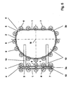
- two chain track guides 1, 2 of a running gear are each composed of an exact straight guide 1 for forward and backward movement or raising and lowering on a facade and respectively an exact partial circle guide 2 for turning and turning on the spot ,
- the two partial circle guides 2 have such a radius and are spaced from each other so that an imaginary full circle with the center M can be hit by both partial circles.
- drive wheels 3a, 3b and deflection wheels 4 are mounted in order to drive circulating chains 5 and guide them in the chain track guides.
- the drive wheels 3a, 3b also serve as deflection wheels on the opposite side of the pure deflection wheels 4th With the chains 5 run on sliders 6.8 attached suckers 7.9 .
- the landing gear is to travel straight up or down on a facade in a straight direction, then all the slides 6 within the two straight guides 1 must be actuated for extension and the associated suckers 7 are subjected to a vacuum. These suckers 7 are thus sucked as only on the running surface. All other slides 8 and 9 suckers are in the normal position, that is, the slide 8 are retracted and their sucker 9 applied without vacuum. If the drive wheels 3a, 3b are driven uniformly in the opposite direction of rotation (drive wheel 3a in the clockwise direction and drive wheel 3b in the counterclockwise direction), the chassis moves forward straight ahead, for example, up a glass facade.
- the running gear moves in reverse direction without a turning maneuver, for example down a glass façade. If one of the slides 6 , 8 , which are moved along the two chain web guides 1, 2 by the two chains 5 , reaches a straight-ahead end or a straight-ahead start, it is reversed.
- the partial circle guides 2 have no influence. That is for the slide 6 within the two linear guides 1 when reaching the Gerad Equipmentsendes: Switch off vacuum generation and then retract slide to the normal position. Likewise applies to the slide 8 outside of the two linear guides 1 when reaching the Geradrysterrorisms: turn on vacuum generation and then extend slide.
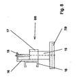
- a sucker 7 touches the running surface F ( FIG. 6 ), it is pressed firmly against the running surface F by the ambient air pressure, and thus this sucker 7 brings about a part of the required holding force. If the teat 7 hits a facade profile P ( FIG. 6 ) during extension of its slide 6 , which is controlled by sensors, the feed movement of the slide 6 stops automatically. As a result, a repulsion of the landing gear from a vertical facade is effectively prevented. In addition, the vacuum generation is deactivated in the relevant sucker 7 . When leaving the linear guide 1 , the slide, now slide 8 , again reversed and retracted to the normal position. As can be seen from FIG. 6 , the stroke of the slides 6, 8 or the clear height of the suckers 7, 9 in the basic position above the running surface F determines the maximum height to be overcome of obstacles, that is to say in particular of facade profiles P.
- the landing gear is stopped and swiveled or turned while stationary.
- the slide 8 are to be extended within the two partial circle guides 2 and to apply vacuum to the associated suction cups 9 , so that they suck in on the running surface F. Only then are suckers 7 aerated on the two linear guides 1 and the slide 6 is pulled into the normal position. Thus, only the suckers 9 of both partial circle guides 2 are sucked on the running surface F , which describe the imaginary circle with the center M within the two partial circle guides 2 . All other slides 6 are in the normal position, that is, the slide 6 are retracted and their suckers 7 without vacuum.
- the two chain track guides of the chassis are carried by a left and a right frame member 10 or be formed directly by the frame members 10, wherein connecting bridges 10, the two frame parts 10 firmly together.
- the slides 6 , 8 carry frame-side slide guides 18 ( FIG. 8 ) in a sliding or roller design for reliable guidance along the revolving chain track guides, as will be explained in detail in connection with FIG. 8 .
- the suckers 7,9 of both endless chains 5 need not, viewed in forward or backward direction, as shown, run synchronously at a height, they may be offset from each other, which is the liability on the running surface F and the overcoming of facade profiles P or similar obstacles rather improved. A corresponding, more or less large offset of the suckers 7,9 with respect to both endless chains 5 to each other will be due to operational reasons.
- a further variant is shown, which also operates with two chain track guides 1.2 .
- the linear guides 1 run outside and the partial circle guides 2 with their imaginary circle center M inside.
- the track width widens when driving straight ahead, the chassis is more stable on the running surface. This can be advantageous for certain work of a climbing robot on a facade.
- this arrangement requires a larger number of suckers 7.9 and four additional pulleys. 4 It is understood that those suckers, which currently run transversely to the direction of travel, must always be raised, regardless of whether a straight-ahead or rotary movement is to be performed.
- the driving sequences correspond to those of the mode of action according to the variant explained in detail in FIG. 1 and FIG. 6 , which is why a repeated description of the driving sequences should be dispensed with.
- Both chain track guides 1.2 of the chassis are in turn carried by a right and a left frame part 10 , which are fixedly connected to each other via connecting bridges 10 .
- the design of the slide 6,8 is identical to the embodiment of FIG. 1, Fig. 6 and Fig. 8 .
- Fig. 3 shows a further variant. It differs from the variant according to FIG. 1 in that the two chain rail guides 1, 2 of the running gear each consist of two parallel, precise straight guides 1 for forward and reverse travel and up and down on one facade and two straight guides 1 respectively exact pitch guides 2 are assembled for turning and turning on the spot.
- the total of four partial circle guides 2 are in turn spaced from each other and designed with such a radius that an imaginary full circle can be hit with a center M as a fulcrum for the chassis.
- drive wheels 3a, 3b and deflection wheels 4 are in turn mounted in order to drive and guide circulating chains 5.
- further deflection wheels 4 are arranged between the outer linear guides 1 and the partial circle guides 2 .
- the drive wheels 3a, 3b also serve as deflection wheels.
- either the suction device 7 on the inner linear guides 1 or the suction device 7 on the outer linear guides 1 can be used depending on the control.
- the outer suckers 7 on the outer straight guides 1 the lane widens, the landing gear is more stable on the running surface. This can be advantageous for certain work of a climbing robot.
- the suckers 9 are used on the pitch circle guides 2 .
- Both chain track guides 1.2 of the chassis are in turn carried by a right and a left frame part 10 , which are fixedly connected to each other via connecting bridges 10 .
- a variant with two chain track guides 1 is presented in a straight line, which are deflected at their deflecting by a deflecting drive roller 3a, 3b and opposite by a guide roller 4 .
- the total of four straight guides 1 allow only a forward and reverse drive of the chassis.
- the respective outer suckers 7 of the two outer straight guides 1 are advantageously used for active driving, and the two inner straight guides 1 are used for returning the then lifted suckers 7 .
- the supports are also provided with slides 12 and suckers 13 .
- the bogie 11 can start and end in height.
- the axis of rotation 14 for the chassis and bogie 11 passes through the center M of the bogie 11 and a central connecting bridge 10 , which bridges the two frame parts 10 of the chassis.
- the running gear is raised relative to the bogie 11 and thus to the running surface F ( FIG. 7 ) and can be steered by motor about the rotation axis 14 .
- FIG. 5 Another variant of a chassis shows Fig. 5 , highly schematic, as well as all other variants.
- two endless chains 5 with suckers 7, 9 are used, but not with mutually mirror-symmetrical or symmetrical chain track guides, but with asymmetrically formed chain track guides 1, 2 .
- a first chain track runs in two straight guides 1 , which are deflected at their ends only by a drive roller 3a and a deflection roller 4 . Accordingly, the chain runs 5 small.
- the second chain track is formed by a partial circle guide 2 and a further straight guide 1 , wherein the pitch circle diameter is greater than the length of the three equally long linear guides. 1
- the pitch circle is thus flattened on the outside and parallel to the two linear guides 1 of the first chain track guide by the further linear guide 1 .
- the inner straight guide 1 or the outer straight guide 1 of the first chain guide 1 and the linear guide 1 on the outer track of the second chain guide 1.2 are used.
- the pivot point M comes to lie asymmetrically to the center of the chassis.
- Both frame 10 of the chassis with the endless chain webs are firmly connected to each other via connecting bridges 10 .
- the slides 6,8 are designed analogously to the previous variants.
- the driving procedures correspond in principle to those after the first one Variant, which is why turn to a detailed description can be waived.
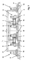
- a suitable for all variants slide 6,8 is drawn out as an assembly. It consists in the example of a pneumatically actuated piston-cylinder unit.
- the piston rod 15 of the slide is fixed and the cylinder 19 guided vertically displaceable using its outer contours in a prismatic cylinder guide 17 , wherein a support 16 for the slide guide 18 and the piston rod 15 , the piston rod 15 with the non-visible piston and the cylinder guide 17 form a coherent, stable assembly and the cylinder 19 carries at its lower end the sucker 7.9 .
- Laterally acting forces are not absorbed by the piston rod 15 , but by the cylinder guide 17 and the cylinder housing.
- the slide 6,8 run chain driven on their slide guides 18 along a circumferential chain track guide 1,2 , which are either formed by a frame member 10 itself or carried by him. To reduce friction, a roller guide may be provided.
- Each sucker 7.9 has an ejector for generating holding force by negative pressure, which is fed via a pressure ring line per chain track guide 1.2 .
- compressed air is also blown into the suckers 7, 9 in order to release the negative pressure.
- a microcontroller controls in cooperation with sensors and pneumatic actuators and control elements, the time sequence of the slide and Saugerzutex.
- the extension force for the suction 7.9 and the suction force of the activated suction 7.9 are advantageously influenced as a function of the extension path of the slide 6.8 (obstacle), only in the fully extended state of a teat 7.9, the full support force and the full vacuum to be built up to avoid lifting the landing gear at larger obstacles. If such an obstacle is detected, the landing gear stops automatically and waits for a suitable maneuver. In addition, it is always checked during driving, whether a sufficiently large adhesion force against crash of the chassis on facades prevails.
- Threatens to be fallen below a program-defined adhesive force for example, because inadmissibly much sucker can not find contact with the running surface (end of the road, facade opening, façade kink, improper road conditions, disturbance in the compressed air supply or vacuum construction on a vacuum cleaner, etc.), stops the chassis automatically.
Claims (15)
- Châssis autogrimpant pour des façades, notamment des façades de verre, comprenant un entraínement constitué de séries sans fin de suceurs commandables,
caractérisé en ce que
les suceurs (7, 9) se déplacent dans le plan de circulation et ont leurs côtés d'aspiration toujours dirigés vers la surface de circulation (F). - Châssis autogrimpant selon la revendication 1,
caractérisé en ce que
les suceurs (7, 9) actuellement activés d'une série sans fin sont posés sur la surface de circulation (F), tandis que les suceurs (9, 7) actuellement non activés d'une série sans fin se trouvent espacés de la surface de circulation (F) d'une distance égale ou supérieure à la hauteur des obstacles (P) à surmonter. - Châssis autogrimpant selon la revendication 1 ou 2,
caractérisé en ce que
les suceurs (7, 9) de chaque série sans fin circulent dans un guidage de voie (1, 2) et sont reliés par un moyen d'entraínement (5). - Châssis autogrimpant selon la revendication 2 ou 3,
caractérisé en ce que
les suceurs (7, 9) sont fixés sur des coulisseaux (6, 8) qui se déplacent le long des guidages de voie (1, 2) du châssis en étant tirés par les moyens d'entraínement. - Châssis autogrimpant selon la revendication 3 ou 4,
caractérisé en ce qu'
une chaíne (5) entraínée par un pignon sert de moyen d'entraínement des suceurs (7, 9). - Châssis autogrimpant selon au moins une des revendications précédentes,
caractérisé en ce qu'
au moins deux guidages rectilignes (1) et parallèles commandés dans le même sens servent au déplacement du châssis en ligne droite (en avant, en arrière). - Châssis autogrimpant selon la revendication 6,
caractérisé en ce que
le châssis est suspendu à un châssis pivotant (11) pouvant tourner par rapport à lui dans le plan de circulation et qui de son côté possède des suceurs (13) mobiles. - Châssis autogrimpant selon au moins une des revendications 1 à 6,
caractérisé en ce que
les guidages de voie (1, 2) sont divisés en guidages rectilignes (1) et guidages semi-circulaires (2). - Châssis autogrimpant selon la revendication 6 ou 8,
caractérisé en ce que
les guidages rectilignes (1) les plus à l'extérieur servent à assurer le déplacement rectiligne. - Châssis autogrimpant selon la revendication 8,
caractérisé en ce qu'
au moins deux guidages semi-circulaires (2), commandés dans le même sens et appartenant à deux guidages de voie (1, 2) servent à faire tourner le châssis (dans le sens où le sens contraire des aiguilles d'une montre). - Châssis autogrimpant selon une des revendications 1 à 4,
caractérisé en ce que
sur chaque suceur (7, 9) est monté un éjecteur qui produit la force de maintien par dépression en étant alimenté par une conduite annulaire de pression, et dans chaque aspirateur (7, 9) de l'air sous pression peut être injecté pour supprimer la dépression. - Châssis autogrimpant selon la revendication 4,
caractérisé en ce qu'
un coulisseau (6, 8) possède une unité piston/cylindre (15, 19) à commande pneumatique, dont le cylindre (19) peut se déplacer le long d'un guidage vertical (17) qui forme avec la tige de piston (15), le support (16) du coulisseau (6, 8) et le guidage de coulisseau (18) fixé à ce support, un groupe constructif compact qui se déplace dans le guidage de voie (1, 2) d'une partie de cadre (10) du châssis, le cylindre (19) guidé verticalement portant le suceur (7, 9) sur sa face inférieure. - Châssis autogrimpant selon une des revendications 1 à 12,
caractérisé en ce qu'
une commande de déplacement surveille la force de maintien du châssis sur une façade et immobilise ce châssis quand il apparaít que cette force de maintien descend en dessous d'une valeur prédéterminée. - Châssis autogrimpant selon une des revendications 2 à 13,
caractérisé en ce qu'
une commande de déplacement assure la descente et la pose du suceur (7, 9) sur la surface de circulation (F) ainsi que la remontée et le retour du suceur (7, 9) à sa position de base. - Châssis autogrimpant selon une des revendications 1 à 10, la revendication 13 et la revendication 14,
caractérisé en ce que
les suceurs (7, 9) sont remplacés par des éléments d'adhérence magnétiques.
Applications Claiming Priority (3)
| Application Number | Priority Date | Filing Date | Title |
|---|---|---|---|
| DE10320570 | 2003-05-07 | ||
| DE10320570A DE10320570B4 (de) | 2003-05-07 | 2003-05-07 | Selbstkletterndes Fahrwerk für Fassaden, insbesondere Glasfassaden |
| PCT/DE2004/000899 WO2004098984A1 (fr) | 2003-05-07 | 2004-05-01 | Chassis autogrimpeur destine a des façades, notamment des façades de verre |
Publications (2)
| Publication Number | Publication Date |
|---|---|
| EP1507696A1 EP1507696A1 (fr) | 2005-02-23 |
| EP1507696B1 true EP1507696B1 (fr) | 2005-07-20 |
Family
ID=33426701
Family Applications (1)
| Application Number | Title | Priority Date | Filing Date |
|---|---|---|---|
| EP04730787A Expired - Lifetime EP1507696B1 (fr) | 2003-05-07 | 2004-05-01 | Chassis autogrimpeur destine a des facades, notamment des facades de verre |
Country Status (7)
| Country | Link |
|---|---|
| EP (1) | EP1507696B1 (fr) |
| JP (1) | JP4262744B2 (fr) |
| KR (1) | KR100804308B1 (fr) |
| AT (1) | ATE299825T1 (fr) |
| DE (2) | DE10320570B4 (fr) |
| ES (1) | ES2243918T3 (fr) |
| WO (1) | WO2004098984A1 (fr) |
Cited By (3)
| Publication number | Priority date | Publication date | Assignee | Title |
|---|---|---|---|---|
| EP2211002A1 (fr) | 2009-01-26 | 2010-07-28 | Niederberger Engineering AG | Installation de nettoyage pour une façade d'un bâtiment |
| DE102009047992B3 (de) * | 2009-10-01 | 2011-03-17 | Niederberger Patent Ag | Kletterroboter für das Befahren von Haftoberflächen |
| DE102009047991B3 (de) * | 2009-10-01 | 2011-03-31 | Niederberger Patent Ag | Kletterroboter für das Befahren von Haftoberflächen |
Families Citing this family (16)
| Publication number | Priority date | Publication date | Assignee | Title |
|---|---|---|---|---|
| DE102007041067A1 (de) * | 2007-08-30 | 2009-03-05 | BSH Bosch und Siemens Hausgeräte GmbH | Verfahrbare Vorrichtung zum Durchführen von Arbeiten an vorzugsweise ebenen Flächen |
| DE102009019168B3 (de) * | 2009-04-18 | 2010-10-14 | Niederberger Patent Ag | Gerät und Verfahren zum Verlegen und/oder Reinigen von Photovoltaikmodulen |
| JP2012061116A (ja) * | 2010-09-15 | 2012-03-29 | Urakami Kk | 窓ガラスなどの清掃装置 |
| CZ2011437A3 (cs) * | 2011-07-19 | 2013-03-20 | Technická univerzita v Liberci | Mobilní plosina pro pohyb po vertikální stene |
| CH705732B1 (de) | 2011-11-07 | 2016-05-13 | Logistics Wash Holding Ag | Fahrwerk für einen Roboter. |
| US10111563B2 (en) | 2013-01-18 | 2018-10-30 | Sunpower Corporation | Mechanism for cleaning solar collector surfaces |
| CN104816765B (zh) * | 2015-05-13 | 2017-03-01 | 浙江工业大学 | 适用于倾斜光滑壁面的爬壁机器人的负压吸附足 |
| CH711196A2 (de) | 2015-06-05 | 2016-12-15 | Logistics Wash Holding Ag | Fahrwerk mit Linear- und Schwenkbewegungen mit bezüglich der Fahrfläche abheb- und absetzbaren Haftfüssen. |
| CN105030144A (zh) * | 2015-06-24 | 2015-11-11 | 苑雪山 | 使用壁面吸附运动机构的幕墙清洗机器人 |
| CN105905181B (zh) * | 2016-05-27 | 2018-01-23 | 燕山大学 | 磁盘吊挂循环爬壁机器人 |
| NO343336B1 (en) * | 2016-10-28 | 2019-02-04 | Haukaas John Kristian | Assembly for carrying out an operation on a net |
| CN107364503A (zh) * | 2017-07-17 | 2017-11-21 | 上海伟匠机器人科技有限公司 | 爬壁装置及其爬行方法、清扫机器人、喷涂机器人 |
| CN110215164A (zh) * | 2018-03-02 | 2019-09-10 | 科沃斯机器人股份有限公司 | 清洁机器人、清洁机器人的转向控制方法及运行控制方法 |
| CN111265142A (zh) * | 2020-02-13 | 2020-06-12 | 河海大学常州校区 | 一种玻璃清洁机器人结构 |
| CN112155484B (zh) * | 2020-08-19 | 2022-02-01 | 江苏澳联科技开发有限公司 | 一种高层建筑外墙清洁机器人 |
| CN113619701B (zh) * | 2021-07-28 | 2023-06-02 | 中国科学院自动化研究所 | 一种多智能体攀爬机器人系统及其控制方法 |
Family Cites Families (21)
| Publication number | Priority date | Publication date | Assignee | Title |
|---|---|---|---|---|
| NL7415509A (nl) * | 1973-12-11 | 1975-06-13 | Sanko Co Ltd | Inrichting beweegbaar te hechten aan een wand. |
| JPS5088794A (fr) * | 1973-12-11 | 1975-07-16 | ||
| DE2737619C3 (de) * | 1977-08-20 | 1981-02-05 | Eugen Kloepper Gmbh & Co, 4600 Dortmund | Vorrichtung zum Reinigen von Flächen, insbesondere von durchsichtigen Dachhäuten von Traglufthallen |
| FR2519576B1 (fr) * | 1982-01-11 | 1985-11-29 | Int Robotic Engineerin | Robot a pattes grimpeur |
| JP2746389B2 (ja) * | 1988-09-28 | 1998-05-06 | 株式会社日立製作所 | クローラ型壁面走行機構 |
| FR2647840A1 (fr) * | 1989-06-02 | 1990-12-07 | Bouygues Sa | Dispositif a ventouses pour porter et deplacer un moyen d'intervention sur une surface, notamment sur une facade de batiment |
| IT1249355B (it) * | 1991-03-29 | 1995-02-23 | Hebor Anstalt | Arpparecchiatura per la pulizia di superfici lisce continue |
| JPH0526767U (ja) * | 1991-09-18 | 1993-04-06 | ヤンマー農機株式会社 | 起立面走行用作業機の走行装置 |
| JPH05285865A (ja) * | 1992-04-09 | 1993-11-02 | Shigeo Hirose | 壁面移動ロボット |
| DE4313719C2 (de) * | 1993-04-27 | 2000-05-31 | Hans Yberle | Transportvorrichtung |
| US5487440A (en) * | 1993-05-18 | 1996-01-30 | Seemann; Henry R. | Robotic apparatus |
| JP2557786B2 (ja) * | 1993-06-22 | 1996-11-27 | 秀嗣 西口 | 壁面走行用ロボット |
| US5551525A (en) * | 1994-08-19 | 1996-09-03 | Vanderbilt University | Climber robot |
| JP3666676B2 (ja) * | 1995-02-10 | 2005-06-29 | 石川島検査計測株式会社 | 磁石車輪ユニットとこれを用いた台車 |
| US5890553A (en) | 1996-08-01 | 1999-04-06 | California Institute Of Technology | Multifunction automated crawling system |
| DE29622167U1 (de) * | 1996-12-20 | 1997-02-20 | Schmid Dietmar Prof Dr Ing | Kletterraupe/Kletter-Roboter |
| DE19727421C2 (de) * | 1997-06-27 | 1999-08-05 | Fraunhofer Ges Forschung | Autonomer Kletterroboter |
| JPH1179019A (ja) * | 1997-09-12 | 1999-03-23 | Toshiba Corp | 壁面移動式切断装置 |
| DE19835038C1 (de) * | 1998-03-11 | 1999-07-01 | Fraunhofer Ges Forschung | Vorrichtung zum Fortbewegen an senkrechten, gewölbten und/oder geneigten Fassaden- und Glasflächen |
| US6090221A (en) * | 1998-09-16 | 2000-07-18 | Skybot Ltd. | System for treating exterior surfaces of buildings |
| DE19907437A1 (de) * | 1999-02-22 | 2000-08-24 | Ridha Azaiz | Mobiler Roboter, insbesondere zur Fortbewegung auf glatten Flächen |
-
2003
- 2003-05-07 DE DE10320570A patent/DE10320570B4/de not_active Expired - Fee Related
-
2004
- 2004-05-01 KR KR1020057015571A patent/KR100804308B1/ko not_active IP Right Cessation
- 2004-05-01 WO PCT/DE2004/000899 patent/WO2004098984A1/fr active Application Filing
- 2004-05-01 EP EP04730787A patent/EP1507696B1/fr not_active Expired - Lifetime
- 2004-05-01 JP JP2006500492A patent/JP4262744B2/ja not_active Expired - Fee Related
- 2004-05-01 DE DE502004000028T patent/DE502004000028D1/de not_active Expired - Lifetime
- 2004-05-01 ES ES04730787T patent/ES2243918T3/es not_active Expired - Lifetime
- 2004-05-01 AT AT04730787T patent/ATE299825T1/de active
Cited By (8)
| Publication number | Priority date | Publication date | Assignee | Title |
|---|---|---|---|---|
| EP2211002A1 (fr) | 2009-01-26 | 2010-07-28 | Niederberger Engineering AG | Installation de nettoyage pour une façade d'un bâtiment |
| WO2010083619A1 (fr) | 2009-01-26 | 2010-07-29 | Niederberger Engineering Ag | Installation de nettoyage pour une façade de bâtiment |
| DE102009047992B3 (de) * | 2009-10-01 | 2011-03-17 | Niederberger Patent Ag | Kletterroboter für das Befahren von Haftoberflächen |
| DE102009047991B3 (de) * | 2009-10-01 | 2011-03-31 | Niederberger Patent Ag | Kletterroboter für das Befahren von Haftoberflächen |
| WO2011038871A1 (fr) | 2009-10-01 | 2011-04-07 | Niederberger Patent Ag | Robot grimpeur destiné au déplacement sur des surfaces d'adhérence |
| WO2011038870A1 (fr) | 2009-10-01 | 2011-04-07 | Niederberger Patent Ag | Robot grimpant destiné à se déplacer sur des surfaces à adhérence |
| US8459384B2 (en) | 2009-10-01 | 2013-06-11 | Anton Niederberger | Climbing robot for travelling over adhesive surfaces |
| US8464815B2 (en) | 2009-10-01 | 2013-06-18 | Anton Niederberger | Climbing robot for travelling over adhesive surfaces |
Also Published As
| Publication number | Publication date |
|---|---|
| ATE299825T1 (de) | 2005-08-15 |
| DE10320570B4 (de) | 2005-04-21 |
| EP1507696A1 (fr) | 2005-02-23 |
| KR100804308B1 (ko) | 2008-02-18 |
| WO2004098984A1 (fr) | 2004-11-18 |
| DE502004000028D1 (de) | 2005-08-25 |
| JP2006524155A (ja) | 2006-10-26 |
| KR20050102136A (ko) | 2005-10-25 |
| ES2243918T3 (es) | 2005-12-01 |
| DE10320570A1 (de) | 2004-12-09 |
| JP4262744B2 (ja) | 2009-05-13 |
Similar Documents
| Publication | Publication Date | Title |
|---|---|---|
| EP1507696B1 (fr) | Chassis autogrimpeur destine a des facades, notamment des facades de verre | |
| EP2483139B1 (fr) | Robot grimpeur destiné au déplacement sur des surfaces d'adhérence | |
| EP2483138B1 (fr) | Robot grimpant destiné à se déplacer sur des surfaces à adhérence | |
| EP2776306B1 (fr) | Châssis pour robot | |
| EP3067298B1 (fr) | Dispositif de chargement ou de dechargement d'un recipient de transport | |
| EP3303107B1 (fr) | Châssis à mouvements linéaires et pivotants | |
| DE602005004182T2 (de) | Anhänger mit heb- und senkbarer Manövrieranordnung | |
| DE1655512C3 (de) | Fahrzeug mit einem schwenkbaren Fahrwerk | |
| WO2017032438A1 (fr) | Système de déplacement pour surfaces cylindriques et/ou surfaces coniques | |
| DE102010015618A1 (de) | Fördereinrichtung für Automatisierungsstraßen | |
| EP3802375A2 (fr) | Procédé et dispositif de transport et de tri de marchandises autonome ou partiellement autonome | |
| DE4237558A1 (fr) | ||
| DE102010004974A1 (de) | Fördersystem zum Transport von Gegenständen und Tauchbehandlungsanlage mit einem solchen | |
| DE202008004190U1 (de) | Roll- oder Gelenkanordnung | |
| WO2004045932A1 (fr) | Systeme de logement pour un vehicule | |
| WO2009140952A2 (fr) | Ensemble à engrenages | |
| EP3106368B1 (fr) | Vehicule agricole | |
| CH679563A5 (fr) | ||
| EP2550187B1 (fr) | Auxiliaire d'acces et installation de traitement de vehicule | |
| DE60109288T2 (de) | Hub- und schwenkantriebsvorrichtung für die tragstruktur eines waggons des kombinierten schienen-/strassentransports | |
| DE102021207321B4 (de) | Antriebseinheit für einen Bodenroboter | |
| DE102015008410A1 (de) | Anlage zum Transportieren von Werkstücken | |
| WO2021063666A1 (fr) | Véhicule lié au sol | |
| DE19839384C1 (de) | Zugmaschine | |
| EP0496236A1 (fr) | Dispositif de guidage d'un poids-lourd le long d'une voie de guidage disposée dans le revêtement routier |
Legal Events
| Date | Code | Title | Description |
|---|---|---|---|
| PUAI | Public reference made under article 153(3) epc to a published international application that has entered the european phase |
Free format text: ORIGINAL CODE: 0009012 |
|
| GRAP | Despatch of communication of intention to grant a patent |
Free format text: ORIGINAL CODE: EPIDOSNIGR1 |
|
| 17P | Request for examination filed |
Effective date: 20041207 |
|
| AK | Designated contracting states |
Kind code of ref document: A1 Designated state(s): AT BE BG CH CY CZ DE DK EE ES FI FR GB GR HU IE IT LI LU MC NL PL PT RO SE SI SK TR |
|
| AX | Request for extension of the european patent |
Extension state: AL HR LT LV MK |
|
| GRAS | Grant fee paid |
Free format text: ORIGINAL CODE: EPIDOSNIGR3 |
|
| GRAA | (expected) grant |
Free format text: ORIGINAL CODE: 0009210 |
|
| AK | Designated contracting states |
Kind code of ref document: B1 Designated state(s): AT BE BG CH CY CZ DE DK EE ES FI FR GB GR HU IE IT LI LU MC NL PL PT RO SE SI SK TR |
|
| PG25 | Lapsed in a contracting state [announced via postgrant information from national office to epo] |
Ref country code: SK Free format text: LAPSE BECAUSE OF FAILURE TO SUBMIT A TRANSLATION OF THE DESCRIPTION OR TO PAY THE FEE WITHIN THE PRESCRIBED TIME-LIMIT Effective date: 20050720 Ref country code: PL Free format text: LAPSE BECAUSE OF FAILURE TO SUBMIT A TRANSLATION OF THE DESCRIPTION OR TO PAY THE FEE WITHIN THE PRESCRIBED TIME-LIMIT Effective date: 20050720 Ref country code: IE Free format text: LAPSE BECAUSE OF FAILURE TO SUBMIT A TRANSLATION OF THE DESCRIPTION OR TO PAY THE FEE WITHIN THE PRESCRIBED TIME-LIMIT Effective date: 20050720 Ref country code: EE Free format text: LAPSE BECAUSE OF FAILURE TO SUBMIT A TRANSLATION OF THE DESCRIPTION OR TO PAY THE FEE WITHIN THE PRESCRIBED TIME-LIMIT Effective date: 20050720 Ref country code: CZ Free format text: LAPSE BECAUSE OF FAILURE TO SUBMIT A TRANSLATION OF THE DESCRIPTION OR TO PAY THE FEE WITHIN THE PRESCRIBED TIME-LIMIT Effective date: 20050720 Ref country code: SI Free format text: LAPSE BECAUSE OF FAILURE TO SUBMIT A TRANSLATION OF THE DESCRIPTION OR TO PAY THE FEE WITHIN THE PRESCRIBED TIME-LIMIT Effective date: 20050720 Ref country code: TR Free format text: LAPSE BECAUSE OF FAILURE TO SUBMIT A TRANSLATION OF THE DESCRIPTION OR TO PAY THE FEE WITHIN THE PRESCRIBED TIME-LIMIT Effective date: 20050720 Ref country code: FI Free format text: LAPSE BECAUSE OF FAILURE TO SUBMIT A TRANSLATION OF THE DESCRIPTION OR TO PAY THE FEE WITHIN THE PRESCRIBED TIME-LIMIT Effective date: 20050720 Ref country code: NL Free format text: LAPSE BECAUSE OF FAILURE TO SUBMIT A TRANSLATION OF THE DESCRIPTION OR TO PAY THE FEE WITHIN THE PRESCRIBED TIME-LIMIT Effective date: 20050720 |
|
| REG | Reference to a national code |
Ref country code: GB Ref legal event code: FG4D Free format text: NOT ENGLISH |
|
| REG | Reference to a national code |
Ref country code: CH Ref legal event code: EP Ref country code: CH Ref legal event code: NV Representative=s name: BOVARD AG PATENTANWAELTE |
|
| GBT | Gb: translation of ep patent filed (gb section 77(6)(a)/1977) |
Effective date: 20050720 |
|
| REG | Reference to a national code |
Ref country code: IE Ref legal event code: FG4D Free format text: LANGUAGE OF EP DOCUMENT: GERMAN |
|
| REF | Corresponds to: |
Ref document number: 502004000028 Country of ref document: DE Date of ref document: 20050825 Kind code of ref document: P |
|
| PG25 | Lapsed in a contracting state [announced via postgrant information from national office to epo] |
Ref country code: GR Free format text: LAPSE BECAUSE OF FAILURE TO SUBMIT A TRANSLATION OF THE DESCRIPTION OR TO PAY THE FEE WITHIN THE PRESCRIBED TIME-LIMIT Effective date: 20051020 Ref country code: DK Free format text: LAPSE BECAUSE OF FAILURE TO SUBMIT A TRANSLATION OF THE DESCRIPTION OR TO PAY THE FEE WITHIN THE PRESCRIBED TIME-LIMIT Effective date: 20051020 Ref country code: BG Free format text: LAPSE BECAUSE OF FAILURE TO SUBMIT A TRANSLATION OF THE DESCRIPTION OR TO PAY THE FEE WITHIN THE PRESCRIBED TIME-LIMIT Effective date: 20051020 Ref country code: SE Free format text: LAPSE BECAUSE OF FAILURE TO SUBMIT A TRANSLATION OF THE DESCRIPTION OR TO PAY THE FEE WITHIN THE PRESCRIBED TIME-LIMIT Effective date: 20051020 |
|
| REG | Reference to a national code |
Ref country code: ES Ref legal event code: FG2A Ref document number: 2243918 Country of ref document: ES Kind code of ref document: T3 |
|
| PG25 | Lapsed in a contracting state [announced via postgrant information from national office to epo] |
Ref country code: PT Free format text: LAPSE BECAUSE OF FAILURE TO SUBMIT A TRANSLATION OF THE DESCRIPTION OR TO PAY THE FEE WITHIN THE PRESCRIBED TIME-LIMIT Effective date: 20051221 |
|
| PG25 | Lapsed in a contracting state [announced via postgrant information from national office to epo] |
Ref country code: HU Free format text: LAPSE BECAUSE OF FAILURE TO SUBMIT A TRANSLATION OF THE DESCRIPTION OR TO PAY THE FEE WITHIN THE PRESCRIBED TIME-LIMIT Effective date: 20060121 |
|
| NLV1 | Nl: lapsed or annulled due to failure to fulfill the requirements of art. 29p and 29m of the patents act | ||
| REG | Reference to a national code |
Ref country code: IE Ref legal event code: FD4D |
|
| ET | Fr: translation filed | ||
| PLBE | No opposition filed within time limit |
Free format text: ORIGINAL CODE: 0009261 |
|
| STAA | Information on the status of an ep patent application or granted ep patent |
Free format text: STATUS: NO OPPOSITION FILED WITHIN TIME LIMIT |
|
| PG25 | Lapsed in a contracting state [announced via postgrant information from national office to epo] |
Ref country code: MC Free format text: LAPSE BECAUSE OF NON-PAYMENT OF DUE FEES Effective date: 20060531 |
|
| 26N | No opposition filed |
Effective date: 20060421 |
|
| REG | Reference to a national code |
Ref country code: CH Ref legal event code: PUE Owner name: NIEDERBERGER-ENGINEERING AG Free format text: UNIQUE CLEANING SYSTEMS GMBH#IM INNENRING 9#09468 GEYER (DE) -TRANSFER TO- NIEDERBERGER-ENGINEERING AG#SCHINHALTENSTRASSE 20A#6370 OBERDORF / STANS (CH) |
|
| REG | Reference to a national code |
Ref country code: GB Ref legal event code: 732E |
|
| PG25 | Lapsed in a contracting state [announced via postgrant information from national office to epo] |
Ref country code: LU Free format text: LAPSE BECAUSE OF NON-PAYMENT OF DUE FEES Effective date: 20060501 |
|
| PG25 | Lapsed in a contracting state [announced via postgrant information from national office to epo] |
Ref country code: RO Free format text: LAPSE BECAUSE OF FAILURE TO SUBMIT A TRANSLATION OF THE DESCRIPTION OR TO PAY THE FEE WITHIN THE PRESCRIBED TIME-LIMIT Effective date: 20050720 |
|
| PG25 | Lapsed in a contracting state [announced via postgrant information from national office to epo] |
Ref country code: CY Free format text: LAPSE BECAUSE OF FAILURE TO SUBMIT A TRANSLATION OF THE DESCRIPTION OR TO PAY THE FEE WITHIN THE PRESCRIBED TIME-LIMIT Effective date: 20050720 |
|
| REG | Reference to a national code |
Ref country code: FR Ref legal event code: TP |
|
| REG | Reference to a national code |
Ref country code: ES Ref legal event code: PC2A |
|
| REG | Reference to a national code |
Ref country code: CH Ref legal event code: PFA Owner name: NIEDERBERGER-ENGINEERING AG Free format text: NIEDERBERGER-ENGINEERING AG#SCHINHALTENSTRASSE 20A#6370 OBERDORF / STANS (CH) -TRANSFER TO- NIEDERBERGER-ENGINEERING AG#SCHINHALTENSTRASSE 20A#6370 OBERDORF / STANS (CH) |
|
| REG | Reference to a national code |
Ref country code: FR Ref legal event code: PLFP Year of fee payment: 13 |
|
| REG | Reference to a national code |
Ref country code: FR Ref legal event code: PLFP Year of fee payment: 14 |
|
| PGFP | Annual fee paid to national office [announced via postgrant information from national office to epo] |
Ref country code: ES Payment date: 20170309 Year of fee payment: 14 |
|
| PGFP | Annual fee paid to national office [announced via postgrant information from national office to epo] |
Ref country code: DE Payment date: 20181130 Year of fee payment: 15 Ref country code: AT Payment date: 20181130 Year of fee payment: 15 |
|
| PGFP | Annual fee paid to national office [announced via postgrant information from national office to epo] |
Ref country code: IT Payment date: 20181130 Year of fee payment: 15 Ref country code: GB Payment date: 20181130 Year of fee payment: 15 Ref country code: BE Payment date: 20181130 Year of fee payment: 15 Ref country code: CH Payment date: 20181130 Year of fee payment: 15 Ref country code: FR Payment date: 20181130 Year of fee payment: 15 |
|
| REG | Reference to a national code |
Ref country code: ES Ref legal event code: FD2A Effective date: 20190912 |
|
| PG25 | Lapsed in a contracting state [announced via postgrant information from national office to epo] |
Ref country code: ES Free format text: LAPSE BECAUSE OF NON-PAYMENT OF DUE FEES Effective date: 20180502 |
|
| REG | Reference to a national code |
Ref country code: DE Ref legal event code: R119 Ref document number: 502004000028 Country of ref document: DE |
|
| REG | Reference to a national code |
Ref country code: CH Ref legal event code: PL |
|
| REG | Reference to a national code |
Ref country code: AT Ref legal event code: MM01 Ref document number: 299825 Country of ref document: AT Kind code of ref document: T Effective date: 20190501 |
|
| GBPC | Gb: european patent ceased through non-payment of renewal fee |
Effective date: 20190501 |
|
| PG25 | Lapsed in a contracting state [announced via postgrant information from national office to epo] |
Ref country code: CH Free format text: LAPSE BECAUSE OF NON-PAYMENT OF DUE FEES Effective date: 20190531 Ref country code: LI Free format text: LAPSE BECAUSE OF NON-PAYMENT OF DUE FEES Effective date: 20190531 Ref country code: AT Free format text: LAPSE BECAUSE OF NON-PAYMENT OF DUE FEES Effective date: 20190501 |
|
| REG | Reference to a national code |
Ref country code: BE Ref legal event code: MM Effective date: 20190531 |
|
| PG25 | Lapsed in a contracting state [announced via postgrant information from national office to epo] |
Ref country code: DE Free format text: LAPSE BECAUSE OF NON-PAYMENT OF DUE FEES Effective date: 20191203 Ref country code: IT Free format text: LAPSE BECAUSE OF NON-PAYMENT OF DUE FEES Effective date: 20190501 Ref country code: GB Free format text: LAPSE BECAUSE OF NON-PAYMENT OF DUE FEES Effective date: 20190501 |
|
| PG25 | Lapsed in a contracting state [announced via postgrant information from national office to epo] |
Ref country code: BE Free format text: LAPSE BECAUSE OF NON-PAYMENT OF DUE FEES Effective date: 20190531 |
|
| PG25 | Lapsed in a contracting state [announced via postgrant information from national office to epo] |
Ref country code: FR Free format text: LAPSE BECAUSE OF NON-PAYMENT OF DUE FEES Effective date: 20190531 |