EP1507696B1 - Automatic climbing mechanism for facades, especially glass facades - Google Patents
Automatic climbing mechanism for facades, especially glass facades Download PDFInfo
- Publication number
- EP1507696B1 EP1507696B1 EP04730787A EP04730787A EP1507696B1 EP 1507696 B1 EP1507696 B1 EP 1507696B1 EP 04730787 A EP04730787 A EP 04730787A EP 04730787 A EP04730787 A EP 04730787A EP 1507696 B1 EP1507696 B1 EP 1507696B1
- Authority
- EP
- European Patent Office
- Prior art keywords
- guides
- automatic climbing
- mechanism according
- climbing mechanism
- suction devices
- Prior art date
- Legal status (The legal status is an assumption and is not a legal conclusion. Google has not performed a legal analysis and makes no representation as to the accuracy of the status listed.)
- Expired - Lifetime
Links
- 230000007246 mechanism Effects 0.000 title claims abstract description 28
- 230000009194 climbing Effects 0.000 title claims abstract description 20
- 239000011521 glass Substances 0.000 title claims abstract description 13
- 239000000853 adhesive Substances 0.000 claims description 4
- 230000001070 adhesive effect Effects 0.000 claims description 4
- 241000252254 Catostomidae Species 0.000 description 39
- 230000033001 locomotion Effects 0.000 description 15
- 238000000034 method Methods 0.000 description 4
- 210000002445 nipple Anatomy 0.000 description 4
- 238000013461 design Methods 0.000 description 3
- 239000003570 air Substances 0.000 description 2
- 239000012080 ambient air Substances 0.000 description 2
- 230000008901 benefit Effects 0.000 description 2
- 238000004140 cleaning Methods 0.000 description 2
- 238000010276 construction Methods 0.000 description 2
- 238000006073 displacement reaction Methods 0.000 description 2
- 238000005516 engineering process Methods 0.000 description 2
- 238000007689 inspection Methods 0.000 description 2
- 238000009418 renovation Methods 0.000 description 2
- 239000000725 suspension Substances 0.000 description 2
- 230000009471 action Effects 0.000 description 1
- 230000008859 change Effects 0.000 description 1
- 230000001427 coherent effect Effects 0.000 description 1
- 230000007423 decrease Effects 0.000 description 1
- 230000001419 dependent effect Effects 0.000 description 1
- 238000011161 development Methods 0.000 description 1
- 230000018109 developmental process Effects 0.000 description 1
- 238000005265 energy consumption Methods 0.000 description 1
- 238000012544 monitoring process Methods 0.000 description 1
- 230000008569 process Effects 0.000 description 1
- 238000012549 training Methods 0.000 description 1
Images


Classifications
-
- B—PERFORMING OPERATIONS; TRANSPORTING
- B62—LAND VEHICLES FOR TRAVELLING OTHERWISE THAN ON RAILS
- B62D—MOTOR VEHICLES; TRAILERS
- B62D55/00—Endless track vehicles
- B62D55/08—Endless track units; Parts thereof
- B62D55/18—Tracks
- B62D55/26—Ground engaging parts or elements
- B62D55/265—Ground engaging parts or elements having magnetic or pneumatic adhesion
-
- B—PERFORMING OPERATIONS; TRANSPORTING
- B66—HOISTING; LIFTING; HAULING
- B66B—ELEVATORS; ESCALATORS OR MOVING WALKWAYS
- B66B9/00—Kinds or types of lifts in, or associated with, buildings or other structures
- B66B9/04—Kinds or types of lifts in, or associated with, buildings or other structures actuated pneumatically or hydraulically
-
- B—PERFORMING OPERATIONS; TRANSPORTING
- B66—HOISTING; LIFTING; HAULING
- B66B—ELEVATORS; ESCALATORS OR MOVING WALKWAYS
- B66B9/00—Kinds or types of lifts in, or associated with, buildings or other structures
- B66B9/02—Kinds or types of lifts in, or associated with, buildings or other structures actuated mechanically otherwise than by rope or cable
Definitions
- the invention relates to a self-climbing chassis for Facades, in particular glass facades, with a drive Endless rows of controllable vacuum cups.
- the self-climbing Chassis for example, carry a glass cleaning robot.
- Other applications relate to self-climbing landing gear for inspection, renovation and transport tasks on facades or the like oblique, vertical or overhanging smooth surfaces.
- Chassis achieve higher working speeds of 3m / min up to 10m / min.
- the locomotion is uniform without Holding breaks and the working cycles: loosen the suction cup, lift it, can track, lower and suck for the relevant Suction cups take place simultaneously.
- the constantly available holding power thus varies only between 80% and 90% and 100%.
- Advantageous is also the lower control effort, as the Working cycles can be forcibly controlled.
- Disadvantageous known undercarriage is the insufficient steerability, such as lateral displacement transversely to the direction of movement and the non-existent ability in the basic mechanism, at vertical Walls, in particular glass facades, facade profiles or overcome similar obstacles.
- the wheel geometry does not provide enough footprint and is for carrying Of suckers relatively unsuitable. Examples of suspensions are in DE 197 27 421 C2, DE 296 22 167 U1, EP 0 505 956 A1, US 5 487,440 and US 6,090,221.
- the chain drive technology In the chassis is the chain drive technology, as they are long in armored tracked vehicles and tracked vehicles used, the currently most viable solution. however must be the circulating driving means, such as chains, bands, ropes or straps that are to realize the locomotion still be provided with suckers. Representative becomes appropriate for all the term "chain” is used for suitable means of propulsion, without any limitation should be.
- the principle is based on the fact that everyone is attached to a chain Sucker goes through an endless loop.
- the driving surface facing suction cups are subjected to vacuum and hold the landing gear on the facade.
- the respective rear suckers have to be ventilated, so that these suckers are released from the driving surface and the Chains can swing these suckers by 180 °.
- the suckers of currently swirled suckers thus show in the of the Driving direction facing away.
- the Carried vacuum cleaner in the direction of travel and again swiveled through 180 °, with which the suckers the driving surface again turned become.
- the application of vacuum, and the Suckers become active and can change the landing gear on the running surface fix. After the landing gear on the sucked suckers they are re-ventilated and pivoted. This process is repeated while driving for each individual sucker continuously.
- the well-known chain chassis for facades differ usually only by how they parallel the suckers after pivoting Place on the driving surface or lift off or swing away (DE 29 622 167 U1), and as the vacuum supply is realized (EP 505 956 A1).
- a big disadvantage of continuously moving drives is that they have no obstacles, such as Glass facade profiles of higher than about 1cm, can overcome. Furthermore can be carried out only very small trim steering movements. Also, they have a very large design Mass and height.
- the object of the invention is an inexpensive, reliable and relatively fast and continuous both before and after also backwards driving, self-climbing chassis lower Mass and height to create, which is very safe at a sloping, vertical or overhanging facade over larger Reach remote control drives, facade profiles of over 1cm overcomes at least 4cm in height, so well steerable is that it can turn on the spot, not on ropes or the like Aids depends and preferably for climbing robots Glass facade cleaning, but also for example for transport, renovation and inspection work, can be used and a minimized tax expenditure and energy consumption for has his business.
- the self-climbing chassis according to the invention has two chain track guides, in contrast to known chain drives not perpendicular to the driving surface, but parallel to the Ride surface of the vehicle are oriented, so laid flat are, which moved along the chain track guides Suction cups maintain their parallel position to the running surface at all times.
- the suckers thus always point to the running surface, regardless of whether they are active or not active.
- attacking backwards on the suckers Slide down a vertical lowering and weaning the nipple the driving surface and a vertical lifting and returning the sucker in the basic position.
- the slides realize thus a parallel and constant distance of the chassis from the driving surface and thus ensure the necessary ground clearance for overcoming obstacles, how special Glass facade profiles.
- the slides are guided along the chain track guides and are among themselves with the chains or functionally equivalent Driving means connected.
- the term "slider" should for all functionally suitable guide components for the suckers are standing.
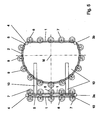
- two chain track guides 1, 2 of a running gear are each composed of an exact straight guide 1 for forward and backward movement or raising and lowering on a facade and respectively an exact partial circle guide 2 for turning and turning on the spot ,
- the two partial circle guides 2 have such a radius and are spaced from each other so that an imaginary full circle with the center M can be hit by both partial circles.
- drive wheels 3a, 3b and deflection wheels 4 are mounted in order to drive circulating chains 5 and guide them in the chain track guides.
- the drive wheels 3a, 3b also serve as deflection wheels on the opposite side of the pure deflection wheels 4th With the chains 5 run on sliders 6.8 attached suckers 7.9 .
- the landing gear is to travel straight up or down on a facade in a straight direction, then all the slides 6 within the two straight guides 1 must be actuated for extension and the associated suckers 7 are subjected to a vacuum. These suckers 7 are thus sucked as only on the running surface. All other slides 8 and 9 suckers are in the normal position, that is, the slide 8 are retracted and their sucker 9 applied without vacuum. If the drive wheels 3a, 3b are driven uniformly in the opposite direction of rotation (drive wheel 3a in the clockwise direction and drive wheel 3b in the counterclockwise direction), the chassis moves forward straight ahead, for example, up a glass facade.
- the running gear moves in reverse direction without a turning maneuver, for example down a glass façade. If one of the slides 6 , 8 , which are moved along the two chain web guides 1, 2 by the two chains 5 , reaches a straight-ahead end or a straight-ahead start, it is reversed.
- the partial circle guides 2 have no influence. That is for the slide 6 within the two linear guides 1 when reaching the Gerad Equipmentsendes: Switch off vacuum generation and then retract slide to the normal position. Likewise applies to the slide 8 outside of the two linear guides 1 when reaching the Geradrysterrorisms: turn on vacuum generation and then extend slide.
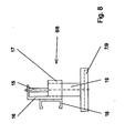
- a sucker 7 touches the running surface F ( FIG. 6 ), it is pressed firmly against the running surface F by the ambient air pressure, and thus this sucker 7 brings about a part of the required holding force. If the teat 7 hits a facade profile P ( FIG. 6 ) during extension of its slide 6 , which is controlled by sensors, the feed movement of the slide 6 stops automatically. As a result, a repulsion of the landing gear from a vertical facade is effectively prevented. In addition, the vacuum generation is deactivated in the relevant sucker 7 . When leaving the linear guide 1 , the slide, now slide 8 , again reversed and retracted to the normal position. As can be seen from FIG. 6 , the stroke of the slides 6, 8 or the clear height of the suckers 7, 9 in the basic position above the running surface F determines the maximum height to be overcome of obstacles, that is to say in particular of facade profiles P.
- the landing gear is stopped and swiveled or turned while stationary.
- the slide 8 are to be extended within the two partial circle guides 2 and to apply vacuum to the associated suction cups 9 , so that they suck in on the running surface F. Only then are suckers 7 aerated on the two linear guides 1 and the slide 6 is pulled into the normal position. Thus, only the suckers 9 of both partial circle guides 2 are sucked on the running surface F , which describe the imaginary circle with the center M within the two partial circle guides 2 . All other slides 6 are in the normal position, that is, the slide 6 are retracted and their suckers 7 without vacuum.
- the two chain track guides of the chassis are carried by a left and a right frame member 10 or be formed directly by the frame members 10, wherein connecting bridges 10, the two frame parts 10 firmly together.
- the slides 6 , 8 carry frame-side slide guides 18 ( FIG. 8 ) in a sliding or roller design for reliable guidance along the revolving chain track guides, as will be explained in detail in connection with FIG. 8 .
- the suckers 7,9 of both endless chains 5 need not, viewed in forward or backward direction, as shown, run synchronously at a height, they may be offset from each other, which is the liability on the running surface F and the overcoming of facade profiles P or similar obstacles rather improved. A corresponding, more or less large offset of the suckers 7,9 with respect to both endless chains 5 to each other will be due to operational reasons.
- a further variant is shown, which also operates with two chain track guides 1.2 .
- the linear guides 1 run outside and the partial circle guides 2 with their imaginary circle center M inside.
- the track width widens when driving straight ahead, the chassis is more stable on the running surface. This can be advantageous for certain work of a climbing robot on a facade.
- this arrangement requires a larger number of suckers 7.9 and four additional pulleys. 4 It is understood that those suckers, which currently run transversely to the direction of travel, must always be raised, regardless of whether a straight-ahead or rotary movement is to be performed.
- the driving sequences correspond to those of the mode of action according to the variant explained in detail in FIG. 1 and FIG. 6 , which is why a repeated description of the driving sequences should be dispensed with.
- Both chain track guides 1.2 of the chassis are in turn carried by a right and a left frame part 10 , which are fixedly connected to each other via connecting bridges 10 .
- the design of the slide 6,8 is identical to the embodiment of FIG. 1, Fig. 6 and Fig. 8 .
- Fig. 3 shows a further variant. It differs from the variant according to FIG. 1 in that the two chain rail guides 1, 2 of the running gear each consist of two parallel, precise straight guides 1 for forward and reverse travel and up and down on one facade and two straight guides 1 respectively exact pitch guides 2 are assembled for turning and turning on the spot.
- the total of four partial circle guides 2 are in turn spaced from each other and designed with such a radius that an imaginary full circle can be hit with a center M as a fulcrum for the chassis.
- drive wheels 3a, 3b and deflection wheels 4 are in turn mounted in order to drive and guide circulating chains 5.
- further deflection wheels 4 are arranged between the outer linear guides 1 and the partial circle guides 2 .
- the drive wheels 3a, 3b also serve as deflection wheels.
- either the suction device 7 on the inner linear guides 1 or the suction device 7 on the outer linear guides 1 can be used depending on the control.
- the outer suckers 7 on the outer straight guides 1 the lane widens, the landing gear is more stable on the running surface. This can be advantageous for certain work of a climbing robot.
- the suckers 9 are used on the pitch circle guides 2 .
- Both chain track guides 1.2 of the chassis are in turn carried by a right and a left frame part 10 , which are fixedly connected to each other via connecting bridges 10 .
- a variant with two chain track guides 1 is presented in a straight line, which are deflected at their deflecting by a deflecting drive roller 3a, 3b and opposite by a guide roller 4 .
- the total of four straight guides 1 allow only a forward and reverse drive of the chassis.
- the respective outer suckers 7 of the two outer straight guides 1 are advantageously used for active driving, and the two inner straight guides 1 are used for returning the then lifted suckers 7 .
- the supports are also provided with slides 12 and suckers 13 .
- the bogie 11 can start and end in height.
- the axis of rotation 14 for the chassis and bogie 11 passes through the center M of the bogie 11 and a central connecting bridge 10 , which bridges the two frame parts 10 of the chassis.
- the running gear is raised relative to the bogie 11 and thus to the running surface F ( FIG. 7 ) and can be steered by motor about the rotation axis 14 .
- FIG. 5 Another variant of a chassis shows Fig. 5 , highly schematic, as well as all other variants.
- two endless chains 5 with suckers 7, 9 are used, but not with mutually mirror-symmetrical or symmetrical chain track guides, but with asymmetrically formed chain track guides 1, 2 .
- a first chain track runs in two straight guides 1 , which are deflected at their ends only by a drive roller 3a and a deflection roller 4 . Accordingly, the chain runs 5 small.
- the second chain track is formed by a partial circle guide 2 and a further straight guide 1 , wherein the pitch circle diameter is greater than the length of the three equally long linear guides. 1
- the pitch circle is thus flattened on the outside and parallel to the two linear guides 1 of the first chain track guide by the further linear guide 1 .
- the inner straight guide 1 or the outer straight guide 1 of the first chain guide 1 and the linear guide 1 on the outer track of the second chain guide 1.2 are used.
- the pivot point M comes to lie asymmetrically to the center of the chassis.
- Both frame 10 of the chassis with the endless chain webs are firmly connected to each other via connecting bridges 10 .
- the slides 6,8 are designed analogously to the previous variants.
- the driving procedures correspond in principle to those after the first one Variant, which is why turn to a detailed description can be waived.
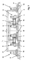
- a suitable for all variants slide 6,8 is drawn out as an assembly. It consists in the example of a pneumatically actuated piston-cylinder unit.
- the piston rod 15 of the slide is fixed and the cylinder 19 guided vertically displaceable using its outer contours in a prismatic cylinder guide 17 , wherein a support 16 for the slide guide 18 and the piston rod 15 , the piston rod 15 with the non-visible piston and the cylinder guide 17 form a coherent, stable assembly and the cylinder 19 carries at its lower end the sucker 7.9 .
- Laterally acting forces are not absorbed by the piston rod 15 , but by the cylinder guide 17 and the cylinder housing.
- the slide 6,8 run chain driven on their slide guides 18 along a circumferential chain track guide 1,2 , which are either formed by a frame member 10 itself or carried by him. To reduce friction, a roller guide may be provided.
- Each sucker 7.9 has an ejector for generating holding force by negative pressure, which is fed via a pressure ring line per chain track guide 1.2 .
- compressed air is also blown into the suckers 7, 9 in order to release the negative pressure.
- a microcontroller controls in cooperation with sensors and pneumatic actuators and control elements, the time sequence of the slide and Saugerzutex.
- the extension force for the suction 7.9 and the suction force of the activated suction 7.9 are advantageously influenced as a function of the extension path of the slide 6.8 (obstacle), only in the fully extended state of a teat 7.9, the full support force and the full vacuum to be built up to avoid lifting the landing gear at larger obstacles. If such an obstacle is detected, the landing gear stops automatically and waits for a suitable maneuver. In addition, it is always checked during driving, whether a sufficiently large adhesion force against crash of the chassis on facades prevails.
- Threatens to be fallen below a program-defined adhesive force for example, because inadmissibly much sucker can not find contact with the running surface (end of the road, facade opening, façade kink, improper road conditions, disturbance in the compressed air supply or vacuum construction on a vacuum cleaner, etc.), stops the chassis automatically.
Landscapes
- Engineering & Computer Science (AREA)
- Mechanical Engineering (AREA)
- Automation & Control Theory (AREA)
- Structural Engineering (AREA)
- Chemical & Material Sciences (AREA)
- Combustion & Propulsion (AREA)
- Transportation (AREA)
- Manipulator (AREA)
- Re-Forming, After-Treatment, Cutting And Transporting Of Glass Products (AREA)
- Glass Compositions (AREA)
- Specific Conveyance Elements (AREA)
Abstract
Description
Die Erfindung betrifft ein selbstkletterndes Fahrwerk für Fassaden, insbesondere Glasfassaden, mit einem Antrieb aus Endlosreihen steuerbarer Vakuumsauger. Das selbstkletternde Fahrwerk kann beispielsweise einen Glasreinigungsroboter tragen. Andere Anwendungen betreffen selbstkletternde Fahrwerke für Inspektions-, Sanier- und Transportaufgaben an Fassaden oder dergleichen schräger, senkrechter oder überhängender glatten Flächen.The invention relates to a self-climbing chassis for Facades, in particular glass facades, with a drive Endless rows of controllable vacuum cups. The self-climbing Chassis, for example, carry a glass cleaning robot. Other applications relate to self-climbing landing gear for inspection, renovation and transport tasks on facades or the like oblique, vertical or overhanging smooth surfaces.
Für das Fortbewegen an senkrechten oder geneigten Fassaden, insbesondere an Glasfassaden, ist es bekannt, selbstkletternde Vorrichtungen einzusetzen, die ihre Haftkraft über Elektromagnetkraft (DE 27 37 619 A1) oder über Vakuum aufbauen, wobei der Begriff "Vakuum" streng genommen für Unterdruck steht. Hinsichtlich der Fortbewegungsart unterscheidet man bei der Vakuumtechnik, auf welche im weiteren abgestellt werden soll, Schreitwerke und Fahrwerke.For moving on vertical or inclined facades, especially on glass facades, it is known self-climbing Use devices that use their adhesive force on electromagnetic force (DE 27 37 619 A1) or build on a vacuum, the term "vacuum" strictly speaking for negative pressure stands. With regard to the mode of locomotion one distinguishes in the vacuum technology, on which further turned off is to be, walkways and landing gear.
Schreitwerke erreichen derzeit nur Arbeitsgeschwindigkeiten bis zu 1m/min. Die Fortbewegung erfolgt periodisch mit Haltepausen. Um Arbeitsgeschwindigkeiten von 1m/ min zu erreichen, muss die Hälfte der Vakuumsauger gelöst, angehoben und vorausgeschoben werden. Danach erfolgt das Absenken und Ansaugen dieser Sauger. Anschließend müssen die restlichen Sauger mit gleicher Vorgehensweise nachgeführt werden. Somit schwankt die verfügbare Haltekraft ständig zwischen 50% und 100%. Werden die Sauger paarweise oder einzeln vorangeschoben bzw. nachgeführt, dann sinkt die Fortbewegungsgeschwindigkeit beträchtlich unter 1m/min. Nachteilig ist ebenfalls der hohe Steuerungs- und Überwachungsaufwand der einzelnen Bewegungen. Ein Vorteil solcher Vorrichtungen ist die einfach zu realisierende Lenkbarkeit durch seitliches Versetzen quer zur Fortbewegungsrichtung und die der Vorrichtung von Anfang an gegebene Fähigkeit, kleinere Hindernisse, wie Glasfassadenprofile, zu überwinden. Schreitende Vorrichtungen sind beschrieben in DE 198 35 038 C1, DE 199 07 437 A1, EP 0 401 120 A1, US 4 674 949, und US 5 551 525.Walking works currently only reach working speeds up to 1m / min. The locomotion occurs periodically with breaks. To reach working speeds of 1m / min, Half of the vacuum cups must be loosened, lifted and pushed forward become. Then the lowering and suction takes place this sucker. Then the rest of the suckers with be tracked the same procedure. Thus, fluctuates the available holding power constantly between 50% and 100%. Become the suckers are pushed in pairs or individually or tracked, then the speed of movement decreases considerably below 1m / min. Another disadvantage is the high Control and monitoring effort of the individual movements. An advantage of such devices is the ease of implementation Steerability by lateral displacement across the Direction of movement and that of the device from the beginning given ability to handle smaller obstacles, such as glass façade profiles, to overcome. Walking devices are described in DE 198 35 038 C1, DE 199 07 437 A1, EP 0 401 120 A1, US 4,674,949, and US 5,551,525.
Fahrwerke erreichen höhere Arbeitsgeschwindigkeiten von 3m/ min bis zu 10m/ min. Die Fortbewegung ist gleichförmig ohne Haltepausen und die Arbeitstakte: Sauger lösen, anheben, nachführen, absenken und ansaugen können für die betreffenden Sauger gleichzeitig erfolgen. Die ständig verfügbare Haltekraft schwankt somit nur zwischen 80% bzw. 90% und 100%. Vorteilhaft ist auch der geringere Steuerungsaufwand, da die Arbeitstakte zwangsgesteuert werden können. Nachteilig an bekannten Fahrwerken ist die ungenügende Lenkbarkeit, wie seitliches Versetzen quer zur Fortbewegungsrichtung und die im Grundmechanismus nicht vorhandene Fähigkeit, an senkrechten Wänden, wie insbesondere auch Glasfassaden, Fassadenprofile oder ähnliche Hindernisse zu überwinden. Die Radgeometrie bietet nicht genug Auflagefläche und ist für das Tragen von Saugern relativ ungeeignet. Beispiele für Fahrwerke sind in DE 197 27 421 C2, DE 296 22 167 U1, EP 0 505 956 A1, US 5 487 440 und US 6 090 221 beschrieben. Chassis achieve higher working speeds of 3m / min up to 10m / min. The locomotion is uniform without Holding breaks and the working cycles: loosen the suction cup, lift it, can track, lower and suck for the relevant Suction cups take place simultaneously. The constantly available holding power thus varies only between 80% and 90% and 100%. Advantageous is also the lower control effort, as the Working cycles can be forcibly controlled. Disadvantageous known undercarriage is the insufficient steerability, such as lateral displacement transversely to the direction of movement and the non-existent ability in the basic mechanism, at vertical Walls, in particular glass facades, facade profiles or overcome similar obstacles. The wheel geometry does not provide enough footprint and is for carrying Of suckers relatively unsuitable. Examples of suspensions are in DE 197 27 421 C2, DE 296 22 167 U1, EP 0 505 956 A1, US 5 487,440 and US 6,090,221.
Bei den Fahrwerken ist die Kettenfahrtechnik, wie sie seit langem bei gepanzerten Kettenfahrzeugen und Raupenfahrzeugen verwendet wird, die derzeit praktikabelste Lösung. Jedoch müssen die umlaufenden Triebmittel, wie Ketten, Bänder, Seile oder Riemen, welche die Fortbewegung realisieren sollen, noch mit Saugern versehen sein. Stellvertretend wird für alle entsprechend geeigneten Triebmittel der Begriff "Kette" verwendet, ohne dass damit irgendeine Einschränkung vorgenommen sein soll.In the chassis is the chain drive technology, as they are long in armored tracked vehicles and tracked vehicles used, the currently most viable solution. however must be the circulating driving means, such as chains, bands, ropes or straps that are to realize the locomotion still be provided with suckers. Representative becomes appropriate for all the term "chain" is used for suitable means of propulsion, without any limitation should be.
Das Prinzip beruht darauf, dass jeder an einer Kette befestigte Sauger eine Endlosschleife durchläuft. Die der Fahrfläche zugewandten Sauger sind mit Vakuum beaufschlagt und halten das Fahrwerk an der Fassade. Setzt man die Ketten in Bewegung, müssen die jeweils hinteren Sauger belüftet werden, damit sich diese Sauger von der Fahrfläche lösen und die Ketten diese Sauger um 180° schwenken können. Die Sauger der aktuell umgeschwenkten Sauger zeigen somit in die von der Fahrfläche abgewandte Richtung. In dieser Lage werden die Sauger in Fahrtrichtung transportiert und wieder um 180° geschwenkt, womit die Sauger der Fahrfläche wieder zugewandt werden. Nun erfolgt die Beaufschlagung mit Vakuum, und die Sauger werden aktiv und können das Fahrwerk auf der Fahrfläche fixieren. Nachdem das Fahrwerk über die angesaugten Sauger hinweggefahren ist, werden diese erneut belüftet und geschwenkt. Dieser Vorgang wiederholt sich während des Fahrens für jeden einzelnen Sauger fortwährend.The principle is based on the fact that everyone is attached to a chain Sucker goes through an endless loop. The driving surface facing suction cups are subjected to vacuum and hold the landing gear on the facade. Put the chains in Movement, the respective rear suckers have to be ventilated, so that these suckers are released from the driving surface and the Chains can swing these suckers by 180 °. The suckers of currently swirled suckers thus show in the of the Driving direction facing away. In this situation, the Carried vacuum cleaner in the direction of travel and again swiveled through 180 °, with which the suckers the driving surface again turned become. Now, the application of vacuum, and the Suckers become active and can change the landing gear on the running surface fix. After the landing gear on the sucked suckers they are re-ventilated and pivoted. This process is repeated while driving for each individual sucker continuously.
Die bekannten Kettenfahrwerke für Fassaden unterscheiden sich meist nur dadurch, wie sie die Sauger nach dem Schwenken parallel auf der Fahrfläche aufsetzen bzw. abheben oder abschwenken (DE 29 622 167 U1), und wie die Vakuumzuführung realisiert ist (EP 505 956 A1).The well-known chain chassis for facades differ usually only by how they parallel the suckers after pivoting Place on the driving surface or lift off or swing away (DE 29 622 167 U1), and as the vacuum supply is realized (EP 505 956 A1).
Ein großer Nachteil der kontinuierlich fahrenden Laufwerke besteht darin, dass sie keine Hindernisse, wie z.B. Glasfassadenprofile von höher als ca. 1cm, überwinden können. Außerdem lassen sich nur sehr kleine Trimmlenkbewegungen ausführen. Auch haben sie konstruktionsbedingt eine sehr große Masse und Bauhöhe.A big disadvantage of continuously moving drives is that they have no obstacles, such as Glass facade profiles of higher than about 1cm, can overcome. Furthermore can be carried out only very small trim steering movements. Also, they have a very large design Mass and height.
Aufgabe der Erfindung ist es, ein preiswertes, betriebssicheres und relativ schnell und kontinuierlich sowohl vor- als auch rückwärts fahrendes, selbstkletterndes Fahrwerk geringer Masse und Bauhöhe zu schaffen, welches sehr sicher an einer schrägen, senkrechten oder überhängenden Fassade über größere Reichweiten ferngesteuert fährt, Fassadenprofile von über 1cm bis mindestens 4cm Höhe überwindet, so gut lenkbar ist, dass es auf der Stelle wenden kann, nicht an Seilen oder ähnlichen Hilfsmitteln hängt und vorzugsweise für Kletterroboter zur Glasfassadenreinigung, aber auch beispielsweise für Transport-, Sanier- und Inspektionsarbeiten, einsetzbar ist und einen minimierten Steueraufwand und Energieverbrauch für seinen Betrieb hat.The object of the invention is an inexpensive, reliable and relatively fast and continuous both before and after also backwards driving, self-climbing chassis lower Mass and height to create, which is very safe at a sloping, vertical or overhanging facade over larger Reach remote control drives, facade profiles of over 1cm overcomes at least 4cm in height, so well steerable is that it can turn on the spot, not on ropes or the like Aids depends and preferably for climbing robots Glass facade cleaning, but also for example for transport, Renovation and inspection work, can be used and a minimized tax expenditure and energy consumption for has his business.
Die Aufgabe wird erfindungsgemäß nach den Merkmalen des Anspruchs
1 gelöst. Vorteilhafte Ausgestaltungen und Weiterentwicklungen
zeigen die abhängigen Ansprüche auf.The object is achieved according to the features of the
Mit der Erfindung ist ein kontinuierlich und relativ schnelles selbstkletterndes Fahrwerk für Roboter geschaffen worden, welches selbständig an einer schrägen, senkrechten oder sogar überhängenden Fassade emporklimmt, Fassadenprofile von mindestens 4cm Höhe überwindet, auf der Stelle wenden kann, einen vergleichsweise geringen Steuer- und Energieaufwand erfordert und nicht an Seilen oder ähnlichen Hilfsmitteln hängt.With the invention is a continuous and relatively fast self-climbing landing gear has been created for robots, which independently on an oblique, vertical or even overhanging façade, facade profiles of at least 4cm height overcomes, can turn on the spot, a comparatively low tax and energy expenditure requires and not on ropes or similar aids hangs.
Das erfindungsgemäße selbstkletternde Fahrwerk hat zwei Kettenbahnführungen, die im Gegensatz zu bekannten Kettenantrieben nicht senkrecht zur Fahrfläche, sondern parallel zur Fahrfläche des Fahrzeugs orientiert sind, also flach gelegt sind, wobei die entlang der Kettenbahnführungen bewegten Sauger ihre parallele Lage zur Fahrfläche stets beibehalten. Die Sauger weisen also stets zur Fahrfläche, ganz gleich, ob sie aktiv sind oder nicht aktiv sind. In Weiterbildung der Erfindung realisieren rückwärtig an den Saugern angreifende Schieber ein senkrechtes Absenken und Absetzen der Sauger auf die Fahrfläche sowie ein senkrechtes Abheben und Zurückführen der Sauger in die Grundstellung. Die Schieber realisieren somit einen parallelen und konstanten Abstand des Fahrwerks von der Fahrfläche und gewährleisten damit die nötige Bodenfreiheit für ein Überwinden von Hindernissen, wie speziell Glasfassadenprofile.The self-climbing chassis according to the invention has two chain track guides, in contrast to known chain drives not perpendicular to the driving surface, but parallel to the Ride surface of the vehicle are oriented, so laid flat are, which moved along the chain track guides Suction cups maintain their parallel position to the running surface at all times. The suckers thus always point to the running surface, regardless of whether they are active or not active. In training of Realize the invention attacking backwards on the suckers Slide down a vertical lowering and weaning the nipple the driving surface and a vertical lifting and returning the sucker in the basic position. The slides realize thus a parallel and constant distance of the chassis from the driving surface and thus ensure the necessary ground clearance for overcoming obstacles, how special Glass facade profiles.
Die Schieber werden längs der Kettenbahnführungen geführt und sind untereinander mit den Ketten oder funktionell gleichwertigen Triebmitteln verbunden. Der Begriff "Schieber" soll dabei für alle funktionell geeigneten Führungsbauteile für die Sauger stehen.The slides are guided along the chain track guides and are among themselves with the chains or functionally equivalent Driving means connected. The term "slider" should for all functionally suitable guide components for the suckers are standing.
Die Erfindung soll anhand von Ausführungsbeispielen näher erläutert werden.The invention is based on exemplary embodiments closer be explained.
In den zugehörigen Zeichnungen zeigen:
- Fig. 1
- eine erste Variante von Kettenbahnführungen eines Fahrwerks in der Draufsicht,
- Fig. 2
- eine weitere Variante von Kettenbahnführungen eines Fahrwerks in der Draufsicht,
- Fig. 3
- eine weitere Variante von Kettenbahnführungen eines Fahrwerks in der Draufsicht,
- Fig. 4
- eine weitere Variante von Kettenbahnführungen eines Fahrwerks in der Draufsicht,
- Fig. 5
- eine weitere Variante von Kettenbahnführungen eines Fahrwerks in der Draufsicht,
- Fig. 6
- die Ansicht nach Fig. 1 von einer Stirnseite aus,
- Fig. 7
- die Ansicht nach Fig. 4 von einer Stirnseite aus und
- Fig. 8
- die Seitenansicht eines Schiebers.
- Fig. 1
- a first variant of chain track guides a landing gear in plan view,
- Fig. 2
- Another variant of chain track guides a landing gear in plan view,
- Fig. 3
- Another variant of chain track guides a landing gear in plan view,
- Fig. 4
- Another variant of chain track guides a landing gear in plan view,
- Fig. 5
- Another variant of chain track guides a landing gear in plan view,
- Fig. 6
- the view of FIG. 1 from a front side,
- Fig. 7
- the view of FIG. 4 from an end face and
- Fig. 8
- the side view of a slider.
Funktionell äquivalente Bauteile sind in allen Figuren mit denselben Bezugszeichen versehen.Functionally equivalent components are in all figures with provided the same reference numerals.
Gemäß der Figuren 1 und 6 sind zwei Kettenbahnführungen 1,2
eines Fahrwerks aus jeweils einer exakten Geradführung 1 für
das Vorwärts- und Rückwärtsfahren bzw. Auf- und Abfahren an
einer Fassade und jeweils einer exakten Teilkreisführung 2
für das Drehen und Wenden auf der Stelle zusammengesetzt. Die
beiden Teilkreisführungen 2 haben einen solchen Radius und
sind so zueinander beabstandet, dass sich ein gedachter Vollkreis
mit dem Mittelpunkt M um beide Teilkreise schlagen
lässt. Zwischen den Geradführungen 1 und den Teilkreisführungen
2 sind Antriebsräder 3a, 3b bzw. Umlenkräder 4 angebracht,
um umlaufende Ketten 5 anzutreiben und in den Kettenbahnführungen
zu führen. Die Antriebsräder 3a, 3b dienen
zugleich als Umlenkräder auf der entgegengesetzten Seite der
reinen Umlenkräder 4. Mit den Ketten 5 laufen an Schiebern
6,8 befestigte Sauger 7,9 um. According to FIGS. 1 and 6 , two chain track guides 1, 2 of a running gear are each composed of an exact
Soll das Fahrwerk an einer Fassade in gerader Richtung senkrecht
nach oben oder unten fahren, müssen alle Schieber 6
innerhalb der beiden Geradführungen 1 zum Ausfahren angesteuert
sein und die dazugehörigen Sauger 7 mit Vakuum beaufschlagt
werden. Diese Sauger 7 sind somit als einzige auf der
Fahrfläche angesaugt. Alle übrigen Schieber 8 und Sauger 9
befinden sich in der Grundstellung, das heißt, die Schieber 8
sind eingefahren und ihre Sauger 9 ohne Vakuum beaufschlagt.
Werden die Antriebsräder 3a, 3b gleichmäßig in entgegengesetzter
Drehrichtung angetrieben (Antriebsrad 3a in Uhrzeigerrichtung
und Antriebsrad 3b in Gegenuhrzeigerrichtung),
bewegt sich das Fahrwerk geradeaus vorwärts, beispielsweise
an einer Glasfassade empor. Wird hingegen das Antriebsrad 3b
in Uhrzeigerrichtung und das Antriebsrad 3a in Gegenuhrzeigerrichtung
angetrieben, bewegt sich das Fahrwerk ohne Wendemanöver
entgegengesetzt, beispielsweise an einer Glasfassade
hinab. Erreicht einer der Schieber 6,8, welche längs der
beiden Kettenbahnführungen 1,2 durch die beiden Ketten 5
bewegt werden, ein Geradführungsende bzw. einen Geradführungsanfang,
wird er umgesteuert. Die Teilkreisführungen 2
haben keinen Einfluss. Das heißt für die Schieber 6 innerhalb
der beiden Geradführungen 1 bei Erreichen des Geradführungsendes:
Vakuumerzeugung abschalten und danach Schieber in die
Grundstellung einfahren. Gleichfalls gilt für die Schieber 8
außerhalb der beiden Geradführungen 1 bei Erreichen des Geradführungsanfangs:
Vakuumerzeugung einschalten und danach
Schieber ausfahren.If the landing gear is to travel straight up or down on a facade in a straight direction, then all the
Berührt ein Sauger 7 die Fahrfläche F (Fig. 6), wird er vom
Umgebungsluftdruck fest an die Fahrfläche F angepresst, und
damit bringt dieser Sauger 7 einen Teil der erforderlichen
Haltekraft auf. Trifft der Sauger 7 beim Ausfahren seines
Schiebers 6 auf ein Fassadenprofil P (Fig. 6), was sensorisch
kontrolliert wird, stoppt die Zustellbewegung des Schiebers 6
automatisch. Dadurch wird ein Abstoßen des Fahrwerks von einer
senkrechten Fassade wirkungsvoll verhindert. Außerdem
wird die Vakuumerzeugung in dem betreffenden Sauger 7 deaktiviert.
Beim Verlassen der Geradführung 1 wird der Schieber,
jetzt Schieber 8, erneut umgesteuert und in die Grundstellung
eingefahren. Wie aus Fig. 6 zu ersehen ist, bestimmt der Hub
der Schieber 6, 8 bzw. die lichte Höhe der Sauger 7,9 in der
Grundstellung über der Fahrfläche F die maximal zu überwindende
Höhe von Hindernissen, also insbesondere von Fassadenprofilen
P.If a
Für Fahrtrichtungsänderungen und Wendemanöver wird das Fahrwerk
angehalten und im Stand geschwenkt oder gedreht. Dazu
sind die Schieber 8 innerhalb der beiden Teilkreisführungen 2
auszufahren und die zugehörige Sauger 9 mit Vakuum zu beaufschlagen,
damit sie sich an der Fahrfläche F ansaugen. Erst
danach werden auf den beiden Geradführungen 1 die Sauger 7
belüftet und die Schieber 6 in die Grundstellung eingezogen.
Es sind somit nur die Sauger 9 beider Teilkreisführungen 2
auf der Fahrfläche F angesaugt, die innerhalb der beiden
Teilkreisführungen 2 den gedachten Kreis mit dem Mittelpunkt
M beschreiben. Alle übrigen Schieber 6 befinden sich in der
Grundstellung, das heißt, die Schieber 6 sind eingefahren und
ihre Sauger 7 ohne Vakuumbeaufschlagung.For changes of direction and turning maneuvers, the landing gear is stopped and swiveled or turned while stationary. For this purpose, the
Treibt man beide Antriebsräder 3a, 3b gleichmäßig in derselben
Drehrichtung entgegen dem Uhrzeigerdrehsinn an, dann
schwenkt das gesamte Fahrwerk in Uhrzeigerdrehrichtung um den
Kreismittelpunkt M, der von den beiden Teilkreisführungen 2
vorgegeben wird. Werden beide Antriebsräder 3a, 3b gleichmäßig
in Uhrzeigerrichtung gedreht, schwenkt das Fahrwerk gegen
die Uhrzeigerrichtung um den Mittelpunkt M. Erreicht einer
der Schieber 6,8, welche längs der Kettenbahnführungen durch
die Ketten 5 bewegt werden, ein Kurvenführungsende bzw. einen
Kurvenführungsanfang, wird er umgesteuert. Die beiden Geradführungen
1 haben keinen Einfluss. Das heißt für die Schieber
8 innerhalb der beiden Teilkreisführungen 2 bei Erreichen des
Kurvenführungsendes: Vakuumerzeugung ausschalten und danach
Schieber 8 in die Grundstellung einfahren. Für die Schieber 6
außerhalb der beiden Teilkreisführungen 2 gilt bei Erreichen
des Kurvenführungsanfangs: Vakuumerzeugung einschalten und
danach Schieber 6 ausfahren. Berührt ein Sauger 9 die Fahrfläche
F, wird er vom Umgebungsluftdruck fest an diese angepresst.
Damit bringt dieser Sauger 9 einen Teil der erforderlichen
Haltekraft auf.If one drives both drive
Trifft der Sauger 9 beim Ausfahren des Schiebers 8 auf ein
Fassadenprofil P, was sensorisch kontrolliert wird, stoppt
automatisch die Zustellbewegung des Schiebers 8, wodurch ein
Abstoßen des Fahrwerks von der Fassade verhindert wird. Außerdem
wird die Vakuumerzeugung für den betreffenden Sauger 9
deaktiviert. Beim Verlassen der Teilkreisführung 2 wird der
Schieber 8 erneut umgesteuert und in die Grundstellung eingefahren.
Wie aus Fig. 6 zu ersehen ist, bestimmt der Hub der
Schieber 6,8 bzw. die lichte Höhe der Sauger 7,9 in eingefahrener
Stellung über der Fahrfläche F die maximal zu überwindende
Höhe von Hindernissen, also insbesondere von Fassadenprofilen
P.Does the
Die beiden Kettenbahnführungen des Fahrwerks werden von einem
linken und einem rechten Rahmenteil 10 getragen oder werden
direkt von den Rahmenteilen 10 ausgebildet, wobei Verbindungsbrücken
10 die beiden Rahmenteile 10 fest miteinander
verbinden. The two chain track guides of the chassis are carried by a left and a
Die Schieber 6,8 tragen rahmenseitig Schieberführungen 18
(Fig. 8) in Gleit- oder Rollenausführung für eine sichere
Führung entlang der umlaufenden Kettenbahnführungen, wie zu
Fig. 8 noch ausführlich erläutert wird.The
Die Sauger 7,9 beider Endlosketten 5 müssen nicht, in Vorwärts-
bzw. Rückwärtsrichtung betrachtet, wie dargestellt,
synchron auf einer Höhe laufen, sie dürfen zueinander versetzt
sein, was die Haftung auf der Fahrfläche F und das
Überwinden von Fassadenprofilen P oder ähnlichen Hindernissen
eher noch verbessert. Ein entsprechender, mehr oder weniger
großer Versatz der Sauger 7,9 bezüglich beider Endlosketten 5
zueinander wird sich von allein betriebsbedingt einstellen.The
In Fig. 2 ist eine weitere Variante dargestellt, die ebenfalls
mit zwei Kettenbahnführungen 1,2 arbeitet. Im Gegensatz
zur Variante nach Fig. 1 laufen die Geradführungen 1 außen
und die Teilkreisführungen 2 mit ihrem gedachten Kreismittelpunkt
M innen. Hierdurch verbreitert sich die Spurbreite bei
Geradeausfahrten, das Fahrwerk steht stabiler auf der Fahrfläche.
Dies kann für bestimmte Arbeiten eines Kletterroboters
an einer Fassade vorteilhaft sein. Allerdings bedingt
diese Anordnung eine größere Anzahl von Saugern 7,9 und vier
zusätzliche Umlenkrollen 4. Es versteht sich, dass sich diejenigen
Sauger, die aktuell quer zur Fahrrichtung laufen,
immer angehoben sein müssen, ganz gleich, ob eine Geradeaus-oder
Drehbewegung vollführt werden soll. Davon abgesehen
entsprechen die Fahrabläufe vom Wirkprinzip denen nach der
vorstehend ausführlich erläuterten Variante gemäß Fig. 1 und
Fig. 6, weshalb auf eine nochmalige Beschreibung der Fahrabläufe
verzichtet werden dürfte. In Fig. 2 , a further variant is shown, which also operates with two chain track guides 1.2 . In contrast to the variant of FIG. 1 , the
Beide Kettenbahnführungen 1,2 des Fahrwerks werden wiederum
von einem rechten und einem linken Rahmenteil 10 getragen,
die über Verbindungsbrücken 10 miteinander fest verbunden
sind. Die Ausbildung der Schieber 6,8 ist identisch zur Ausführung
nach Fig. 1, Fig. 6 und Fig. 8.Both chain track guides 1.2 of the chassis are in turn carried by a right and a
Fig. 3 zeigt eine weitere Variante. Sie unterscheidet sich
von der Variante nach Fig. 1 dadurch, dass die beiden Kettenbahnführungen
1,2 des Fahrwerks aus jeweils zwei parallelen
exakten Geradführungen 1 für das Vorwärts- und Rückwärtsfahren
bzw. Auf- und Abfahren an einer Fassade und jeweils zwei
die Geradführungen 1 verbindenden exakten Teilkreisführungen
2 für das Drehen und Wenden auf der Stelle zusammengesetzt
sind. Die insgesamt vier Teilkreisführungen 2 sind wiederum
so zueinander beabstandet und mit einem solchen Radius ausgeführt,
dass sich ein gedachter Vollkreis mit einem Mittelpunkt
M als Drehpunkt für das Fahrwerk schlagen lässt. Zwischen
den inneren Geradführungen 1 und den sich anschließenden
Teilkreisführungen 2 sind wiederum Antriebsräder 3a, 3b
bzw. Umlenkräder 4 angebracht, um umlaufende Ketten 5 anzutreiben
und zu führen. Außerdem sind weitere Umlenkräder 4
zwischen den äußeren Geradführungen 1 und den Teilkreisführungen
2 angeordnet. Die Antriebsräder 3a, 3b dienen zugleich
als Umlenkräder. Mit den Endlosketten 5 laufen an Schiebern
6,8 befestigte Sauger 7,9 um. Fig. 3 shows a further variant. It differs from the variant according to FIG. 1 in that the two chain rail guides 1, 2 of the running gear each consist of two parallel, precise
Zur Geradfahrt können entweder steuerungsabhängig die Sauger
7 an den inneren Geradführungen 1 oder die Sauger 7 an den
äußeren Geradführungen 1 eingesetzt werden. Durch Verwendung
der äußeren Sauger 7 auf den äußeren Geradführungen 1 verbreitert
sich die Fahrspur, das Fahrwerk steht stabiler auf
der Fahrfläche. Dies kann für bestimmte Arbeiten eines Kletterroboters
vorteilhaft sein. Für Drehbewegungen werden die
Sauger 9 auf den Teilkreis-Führungen 2 eingesetzt.For driving straight, either the
Beide Kettenbahnführungen 1,2 des Fahrwerks werden wiederum
von einem rechten und einem linken Rahmenteil 10 getragen,
die über Verbindungsbrücken 10 miteinander fest verbunden
sind.Both chain track guides 1.2 of the chassis are in turn carried by a right and a
Die Fahrabläufe entsprechen prinzipiell denen nach den vorgenannten Varianten, weshalb auf eine ausführliche Beschreibung verzichtet wird.The driving procedures correspond in principle to those according to the aforementioned Variants, which is why on a detailed description is waived.
In Fig. 4 und Fig. 7 ist eine Variante mit zwei Kettenbahnführungen
1 in Geradführung vorgestellt, die an ihren Umlenkenden
durch eine umlenkende Antriebsrolle 3a, 3b und entgegengesetzt
durch eine Umlenkrolle 4 umgelenkt werden. Die
insgesamt vier Geradführungen 1 erlauben lediglich ein Vorund
Rückwärtsfahren des Fahrwerks. Zur Verbreiterung der
Fahrspur werden in vorteilhafter Weise zum aktiven Fahren die
jeweils äußeren Sauger 7 der beiden äußeren Geradführungen 1
verwendet und die beiden inneren Geradführungen 1 zum Rückführen
der dann angehobenen Sauger 7 verwendet.In Fig. 4 and Fig. 7 , a variant with two chain track guides 1 is presented in a straight line, which are deflected at their deflecting by a deflecting
Zum Drehen hängt das Fahrwerk in einem in der Fahrebene relativ
zum Fahrwerk verdrehbaren Drehgestell 11, dessen Stützen
gleichfalls mit Schiebern 12 und Saugern 13 versehen sind.
Somit lässt sich das Drehgestell 11 höhenmäßig aus- und einfahren.
Die Drehachse 14 für das Fahrwerk und Drehgestell 11
geht durch den Mittelpunkt M des Drehgestells 11 und eine
mittige Verbindungsbrücke 10, die die beiden Rahmenteile 10
des Fahrwerks überbrückt. Im ausgefahrenen Zustand der Sauger
13 wird das Fahrwerk relativ zum Drehgestell 11 und damit zur
Fahrfläche F (Fig. 7) angehoben und kann motorisch um die
Drehachse 14 gelenkt werden.To rotate the suspension hangs in a rotatable in the driving plane relative to the
Eine weitere Variante eines Fahrwerks zeigt Fig. 5, stark
schematisiert, wie auch alle übrigen Varianten. Es werden
wieder zwei Endlosketten 5 mit Saugern 7,9 verwendet, allerdings
nicht mit zueinander spiegelsymmetrischen oder symmetrischen
Kettenbahnführungen, sondern mit asymmetrisch ausgebildeten
Kettenbahnführungen 1,2. Eine erste Kettenbahn läuft
in zwei Geradführungen 1, die an ihren Enden lediglich durch
eine Antriebsrolle 3a und eine Umlenkrolle 4 umgelenkt werden.
Entsprechend schmal läuft die Kette 5 um. Die zweite
Kettenbahn wird von einer Teilkreisführung 2 und einer weiteren
Geradführung 1 gebildet, wobei der Teilkreisdurchmesser
größer ist als die Länge der drei gleichlangen Geradführungen
1. Der Teilkreis ist also außenseitig und parallel zu den
beiden Geradführungen 1 der ersten Kettenbahnführung durch
die weitere Geradführung 1 abgeplattet. Für Geradefahrten
werden die innere Geradführung 1 oder die äußere Geradführung
1 der ersten Kettenbahnführung 1 und die Geradführung 1 auf
der Außenbahn der zweiten Kettenbahnführung 1,2 benutzt. Zum
Drehen wird die Teilkreisführung 2 der zweiten Kettenbahnführung
1,2 verwendet, wobei der Drehpunkt M asymmetrisch zur
Fahrwerkmitte zu liegen kommt. Der Vorteil dieser Variante
liegt in der sehr sicheren Haftung des Fahrwerks an einer
Fassade sowohl beim Geradeausfahren als auch beim Drehen, und
man kommt dennoch mit weniger Saugern 7,9 aus als nach der
Variante gemäß Fig. 3.Another variant of a chassis shows Fig. 5 , highly schematic, as well as all other variants. Again, two
Beide Rahmen 10 des Fahrwerks mit den Endloskettenbahnen sind
über Verbindungsbrücken 10 miteinander fest verbunden. Die
Schieber 6,8 sind analog zu den vorhergehenden Varianten
ausgeführt. Both
Die Fahrabläufe entsprechen prinzipiell denen nach der ersten Variante, weshalb auf eine ausführliche Beschreibung wiederum verzichtet werden kann.The driving procedures correspond in principle to those after the first one Variant, which is why turn to a detailed description can be waived.
In Fig. 8 ist ein für alle Varianten geeigneter Schieber 6,8
als Baugruppe herausgezeichnet. Er besteht im Beispiel aus
einer pneumatisch betätigten Kolben-Zylindereinheit. Um eine
besonders kompakte und dennoch stabile Bauweise des Schiebers
zu erreichen, ist die Kolbenstange 15 des Schiebers fest
angeordnet und der Zylinder 19 unter Einsatz seiner Außenkonturen
höhenverschieblich in einer prismatischen Zylinderführung
17 geführt, wobei eine Stütze 16 für die Schieberführung
18 und die Kolbenstange 15, die Kolbenstange 15 mit dem nicht
sichtbaren Kolben und die Zylinderführung 17 eine zusammenhängende,
stabile Baugruppe ausbilden und der Zylinder 19 an
seinem unteren Ende den Sauger 7,9 trägt. Seitlich wirkende
Kräfte werden nicht von der Kolbenstange 15 aufgenommen,
sondern von der Zylinderführung 17 und dem Zylindergehäuse.
Die Schieber 6,8 laufen kettengetrieben an ihren Schieberführungen
18 entlang einer umlaufenden Kettenbahnführung 1,2,
die von einem Rahmenteil 10 entweder selbst ausgebildet werden
oder von ihm getragen werden. Zur Verminderung der Reibung
kann eine Rollenführung vorgesehen sein.In Fig. 8 a suitable for all variants slide 6,8 is drawn out as an assembly. It consists in the example of a pneumatically actuated piston-cylinder unit. In order to achieve a particularly compact and yet stable construction of the slide, the
Auf der Oberseite des Saugers 7,9 sind nicht näher dargestellte
Steuerelemente für den Saugerbetrieb angeordnet.
Jeder Sauger 7,9 besitzt einen Ejektor zur Erzeugung von
Haltekraft durch Unterdruck, der über eine Druckringleitung
je Kettenbahnführung 1,2 zugeführt wird. Zwecks schnellen
Lösens von der Fahrfläche F wird Druckluft auch zum Aufheben
des Unterdrucks in die Sauger 7,9 eingeblasen. Eine Mikrokontroller
steuert in Zusammenarbeit mit Sensoren und pneumatischen
Stell- und Regelgliedern die zeitliche Abfolge der
Schieber- und Saugerzustände. Dabei werden die Ausfahrkraft
für die Sauger 7,9 und die Saugkraft der aktivierten Sauger
7,9 vorteilhaft in Abhängigkeit des Ausfahrweges der Schieber
6,8 (Hindernis) beeinflusst, wobei erst im voll ausgefahrenen
Zustand eines Saugers 7,9 die volle Stützkraft und der volle
Unterdruck aufgebaut werden, um ein Ausheben des Fahrwerks an
größeren Hindernissen zu vermeiden. Wird ein solcherart Hindernis
festgestellt, hält das Fahrwerk automatisch an und
wartet auf ein geeignetes Fahrmanöver. Außerdem wird im Fahrbetrieb
stets geprüft, ob eine genügend große Haftkraft gegen
Absturz des Fahrwerks an Fassaden herrscht. Droht eine programmmäßig
festgelegte Haftkraft unterschritten zu werden,
beispielsweise weil unzulässig viel Sauger keinen Kontakt zur
Fahrfläche finden (Fahrbahnende, Fassadenöffnung, Fassadenknick,
ungeeignete Fahrbahnbeschaffenheit, Störung in der
Druckluftzufuhr bzw. im Vakuumaufbau an einem Sauger u. a.),
hält das Fahrwerk automatisch an. On the top of the teat 7.9 controls not shown in detail for the suction operation are arranged. Each sucker 7.9 has an ejector for generating holding force by negative pressure, which is fed via a pressure ring line per chain track guide 1.2 . For the purpose of quickly releasing the running surface F , compressed air is also blown into the
- 1,21.2
- KettenbahnführungChain web guide
- 11
- Geradführung einer KettenbahnführungStraight guide of a chain track guide
- 22
- Teilkreisführung einer KettenbahnführungPartial circuit guide of a chain track guide
- 3a, 3b3a, 3b
- Antriebsräderdrive wheels
- 44
- Umlenkräderguide wheels
- 55
- KetteChain
- 6,86.8
- Schieber des FahrwerksSlider of the chassis
- 66
- Schieber, aktuell geradgeführtSlider, currently straight
- 88th
- Schieber, aktuell teilkreisgeführtSlider, currently semi-circular
- 7,97.9
- Saugersucker
- 77
- Sauger, aktuell geradgeführtSucker, currently straight
- 99
- Sauger, aktuell teilkreisgeführtSuction cup, currently semi-circular
- 1010
- rechter und linker Rahmen mit Verbindungsbrückenright and left frame with connecting bridges
- 1111
- Drehgestellbogie
- 1212
- Schieber des DrehgestellsSlider of the bogie
- 1313
- Sauger des DrehgestellschiebersSucker of the bogie pusher
- 1414
- Drehachseaxis of rotation
- 1515
- Kolbenstangepiston rod
- 1616
- Stützesupport
- 1717
- Zylinderführungcylinder guide
- 1818
- Schieberführungslide guide
- 1919
- Zylindergehäusecylinder housing
- MM
- Mittelpunkt der Teilkreisführungen 2Center of the part circle guides 2
- FF
- Fahrbahn (Fassade)Roadway (facade)
- PP
- Fassadenprofilfacade profile
Claims (15)
- Automatic climbing mechanism for façades, especially glass façades, with a drive comprising endless lines of controllable suction devices, charactensed in that the suction devices (7, 9) rotate in the driving plane and their suction sides always point to the driving surface (F).
- Automatic climbing mechanism according to claim 1, characterised in that the currently activated suction devices (7, 9) of an endless line rest on the driving surface (F) and currently inactivated suction devices (9, 7) of an endless line rotate at a distance from the driving surface (D), which is equal to or greater than the height of obstacles to be overcome (P).
- Automatic climbing mechanism according to claim 1 or 2, characterised in that the suction devices (7, 9) of each endless line rotate in a track guide (1, 2) and are connected together by a drive means (5).
- Automatic climbing mechanism according to claim 2 and 3, characterised in that the suction devices (7, 9) are secured to slides (6, 8), which are drawn along the tracks guides (1, 2) of the mechanism by the drive means.
- Automatic climbing mechanism according to claim 3 or 4, characterised in that a chain-wheel driven chain (5) functions as the drive means for the suction devices (7, 9).
- Automatic climbing mechanism according to at least one of the preceding claims, characterised in that at least two straight guides (1) driven in the same direction and running parallel to one another in the mechanism are used for driving the mechanism straight on (forwards drive, reverse drive).
- Automatic climbing mechanism according to claim 6, characterised in that the mechanism is suspended with its extendable suction devices (13) on a rotary frame (11) which is rotatable in the drive plane relative to the mechanism.
- Automatic climbing mechanism according to at least one of claims 1 to 6, characterised in that the track guides (1, 2) are divided into straight guides (1) and part circular guides (2).
- Automatic climbing mechanism according to claim 6 or 8, characterised in that the outermost straight guides (1) are used for driving straight on.
- Automatic climbing mechanism according to claim 8, characterised in that at least two part-circular guides (2) driven in the same direction of two track guides (1,2) are used for rotating the mechanism (clockwise, anticlockwise).
- Automatic climbing mechanism according to one of claims 1 to 4, characterised in that an ejector is arranged on every suction device (7, 9) to generate holding force at low pressure, which is supplied via a pressing ring line, and compressed air can be blown into each suction device (7, 9) to equalise the low pressure.
- Automatic climbing mechanism according to claim 4, characterised in that a slide (6, 8) comprises a pneumatically drivable piston cylinder unit (15, 19), whereby the cylinder (19) can be moved vertically along a vertical cylinder guide (17), which forms a compact subunit with the piston rod (15) and a support (16) of the slide (6, 8) with the slide guide (18) secured thereon, which subunit runs in the track guide (1, 2) of a frame section (10) of the mechanism, and whereby the vertically guided cylinder (19) supports the suction device (7, 9) underneath.
- Automatic climbing mechanism according to one of claims 1 to 12, characterised in that a drive control system monitors the adhesive force of the mechanism on a façade and stops the mechanism if the required degree of adhesion is not reached.
- Automatic climbing mechanism according to one of claims 2 to 13, characterised in that a drive control system initiates the lowering and placing of the suction devices (7, 9) onto the driving surface (F) and raises and returns the suction devices (7, 9) to the initial position.
- Automatic climbing mechanism according to claims 1 to 10, 13 and 14, characterised in that the suction devices (7, 9) are replaced by magnetic adhesive elements.
Applications Claiming Priority (3)
| Application Number | Priority Date | Filing Date | Title |
|---|---|---|---|
| DE10320570A DE10320570B4 (en) | 2003-05-07 | 2003-05-07 | Self-climbing landing gear for facades, in particular glass facades |
| DE10320570 | 2003-05-07 | ||
| PCT/DE2004/000899 WO2004098984A1 (en) | 2003-05-07 | 2004-05-01 | Automatic climbing mechanism for facades, especially glass facades |
Publications (2)
| Publication Number | Publication Date |
|---|---|
| EP1507696A1 EP1507696A1 (en) | 2005-02-23 |
| EP1507696B1 true EP1507696B1 (en) | 2005-07-20 |
Family
ID=33426701
Family Applications (1)
| Application Number | Title | Priority Date | Filing Date |
|---|---|---|---|
| EP04730787A Expired - Lifetime EP1507696B1 (en) | 2003-05-07 | 2004-05-01 | Automatic climbing mechanism for facades, especially glass facades |
Country Status (7)
| Country | Link |
|---|---|
| EP (1) | EP1507696B1 (en) |
| JP (1) | JP4262744B2 (en) |
| KR (1) | KR100804308B1 (en) |
| AT (1) | ATE299825T1 (en) |
| DE (2) | DE10320570B4 (en) |
| ES (1) | ES2243918T3 (en) |
| WO (1) | WO2004098984A1 (en) |
Cited By (3)
| Publication number | Priority date | Publication date | Assignee | Title |
|---|---|---|---|---|
| EP2211002A1 (en) | 2009-01-26 | 2010-07-28 | Niederberger Engineering AG | Cleaning device for a façade of a building |
| DE102009047992B3 (en) * | 2009-10-01 | 2011-03-17 | Niederberger Patent Ag | Climbing robot for driving on adhesive surfaces |
| DE102009047991B3 (en) * | 2009-10-01 | 2011-03-31 | Niederberger Patent Ag | Climbing robot for driving on adhesive surfaces |
Families Citing this family (18)
| Publication number | Priority date | Publication date | Assignee | Title |
|---|---|---|---|---|
| DE102007041067A1 (en) * | 2007-08-30 | 2009-03-05 | BSH Bosch und Siemens Hausgeräte GmbH | Movable device for performing work on preferably flat surfaces |
| DE102009019168B3 (en) * | 2009-04-18 | 2010-10-14 | Niederberger Patent Ag | Apparatus and method for laying and / or cleaning photovoltaic modules |
| JP2012061116A (en) * | 2010-09-15 | 2012-03-29 | Urakami Kk | Cleaning device of window glass or the like |
| CZ303697B6 (en) * | 2011-07-19 | 2013-03-20 | Technická univerzita v Liberci | Mobile platform for movement on vertical wall |
| CH705732B1 (en) | 2011-11-07 | 2016-05-13 | Logistics Wash Holding Ag | Suspension for a robot. |
| US10111563B2 (en) | 2013-01-18 | 2018-10-30 | Sunpower Corporation | Mechanism for cleaning solar collector surfaces |
| CN104816765B (en) * | 2015-05-13 | 2017-03-01 | 浙江工业大学 | It is applied to the negative-pressure adsorption foot of the climbing robot tilting hydraulically smooth surface |
| CH711196A2 (en) | 2015-06-05 | 2016-12-15 | Logistics Wash Holding Ag | Chassis with linear and pivoting movements with detachable feet detachable with respect to the travel surface. |
| CN105030144A (en) * | 2015-06-24 | 2015-11-11 | 苑雪山 | Curtain wall cleaning robot using wall suction movement mechanism |
| CN105905181B (en) * | 2016-05-27 | 2018-01-23 | 燕山大学 | Disk hanging circulation climbing robot |
| NO343336B1 (en) * | 2016-10-28 | 2019-02-04 | Haukaas John Kristian | Assembly for carrying out an operation on a net |
| CN107364503A (en) * | 2017-07-17 | 2017-11-21 | 上海伟匠机器人科技有限公司 | Climb wall device and its method of creeping, sweeping robot, spray robot |
| CN110215164B (en) * | 2018-03-02 | 2024-08-30 | 科沃斯机器人股份有限公司 | Cleaning robot, steering control method of cleaning robot and operation control method |
| CN111483529A (en) * | 2019-01-28 | 2020-08-04 | 上海识质电力科技有限公司 | Climbing robot with pneumatic control device |
| CN111265142A (en) * | 2020-02-13 | 2020-06-12 | 河海大学常州校区 | Glass cleaning robot structure |
| CN112155484B (en) * | 2020-08-19 | 2022-02-01 | 江苏澳联科技开发有限公司 | High-rise building outer wall cleaning robot |
| CN113619701B (en) * | 2021-07-28 | 2023-06-02 | 中国科学院自动化研究所 | Multi-agent climbing robot system and control method thereof |
| CN113733073B (en) * | 2021-09-26 | 2023-03-24 | 七腾机器人有限公司 | Robot |
Family Cites Families (21)
| Publication number | Priority date | Publication date | Assignee | Title |
|---|---|---|---|---|
| JPS5088794A (en) * | 1973-12-11 | 1975-07-16 | ||
| NL7415509A (en) * | 1973-12-11 | 1975-06-13 | Sanko Co Ltd | DEVICE MOVABLE TO ATTACH TO A WALL. |
| DE2737619C3 (en) * | 1977-08-20 | 1981-02-05 | Eugen Kloepper Gmbh & Co, 4600 Dortmund | Device for cleaning surfaces, in particular the transparent roof skins of air domes |
| FR2519576B1 (en) * | 1982-01-11 | 1985-11-29 | Int Robotic Engineerin | CLIMBING ROBOT |
| JP2746389B2 (en) * | 1988-09-28 | 1998-05-06 | 株式会社日立製作所 | Crawler type wall running mechanism |
| FR2647840A1 (en) * | 1989-06-02 | 1990-12-07 | Bouygues Sa | VENTOUS DEVICE FOR CARRYING AND MOVING A MEANS OF INTERVENTION ON A SURFACE, IN PARTICULAR ON A BUILDING FACADE |
| IT1249355B (en) * | 1991-03-29 | 1995-02-23 | Hebor Anstalt | CONTINUOUS SMOOTH SURFACE CLEANING EQUIPMENT |
| JPH0526767U (en) * | 1991-09-18 | 1993-04-06 | ヤンマー農機株式会社 | Traveling equipment for work machines for standing surface travel |
| JPH05285865A (en) * | 1992-04-09 | 1993-11-02 | Shigeo Hirose | Wall surface moving robot |
| DE4313719C2 (en) * | 1993-04-27 | 2000-05-31 | Hans Yberle | Transport device |
| US5487440A (en) * | 1993-05-18 | 1996-01-30 | Seemann; Henry R. | Robotic apparatus |
| JP2557786B2 (en) * | 1993-06-22 | 1996-11-27 | 秀嗣 西口 | Robot for wall traveling |
| US5551525A (en) * | 1994-08-19 | 1996-09-03 | Vanderbilt University | Climber robot |
| JP3666676B2 (en) * | 1995-02-10 | 2005-06-29 | 石川島検査計測株式会社 | Magnet wheel unit and cart using it |
| US5890553A (en) | 1996-08-01 | 1999-04-06 | California Institute Of Technology | Multifunction automated crawling system |
| DE29622167U1 (en) * | 1996-12-20 | 1997-02-20 | Schmid, Dietmar, Prof.Dr.-Ing., 73457 Essingen | Climbing caterpillar / climbing robot |
| DE19727421C2 (en) * | 1997-06-27 | 1999-08-05 | Fraunhofer Ges Forschung | Autonomous climbing robot |
| JPH1179019A (en) * | 1997-09-12 | 1999-03-23 | Toshiba Corp | Wall-moving type cutting device |
| DE19835038C1 (en) * | 1998-03-11 | 1999-07-01 | Fraunhofer Ges Forschung | Adjustable mounting for cleaning robot for glass panels on building facade |
| US6090221A (en) * | 1998-09-16 | 2000-07-18 | Skybot Ltd. | System for treating exterior surfaces of buildings |
| DE19907437A1 (en) * | 1999-02-22 | 2000-08-24 | Ridha Azaiz | Mobile robot, especially for moving across smooth surfaces, has mechanical connection between rotating drive part and reciprocating drive part, e.g. belt and wheel for transfer of rotation |
-
2003
- 2003-05-07 DE DE10320570A patent/DE10320570B4/en not_active Expired - Fee Related
-
2004
- 2004-05-01 AT AT04730787T patent/ATE299825T1/en active
- 2004-05-01 WO PCT/DE2004/000899 patent/WO2004098984A1/en active Application Filing
- 2004-05-01 DE DE502004000028T patent/DE502004000028D1/en not_active Expired - Lifetime
- 2004-05-01 EP EP04730787A patent/EP1507696B1/en not_active Expired - Lifetime
- 2004-05-01 JP JP2006500492A patent/JP4262744B2/en not_active Expired - Fee Related
- 2004-05-01 KR KR1020057015571A patent/KR100804308B1/en not_active IP Right Cessation
- 2004-05-01 ES ES04730787T patent/ES2243918T3/en not_active Expired - Lifetime
Cited By (8)
| Publication number | Priority date | Publication date | Assignee | Title |
|---|---|---|---|---|
| EP2211002A1 (en) | 2009-01-26 | 2010-07-28 | Niederberger Engineering AG | Cleaning device for a façade of a building |
| WO2010083619A1 (en) | 2009-01-26 | 2010-07-29 | Niederberger Engineering Ag | Cleaning system for a facade of a building |
| DE102009047992B3 (en) * | 2009-10-01 | 2011-03-17 | Niederberger Patent Ag | Climbing robot for driving on adhesive surfaces |
| DE102009047991B3 (en) * | 2009-10-01 | 2011-03-31 | Niederberger Patent Ag | Climbing robot for driving on adhesive surfaces |
| WO2011038871A1 (en) | 2009-10-01 | 2011-04-07 | Niederberger Patent Ag | Climbing robot for travelling over adhesive surfaces |
| WO2011038870A1 (en) | 2009-10-01 | 2011-04-07 | Niederberger Patent Ag | Climbing robot for travelling over adhesive surfaces |
| US8459384B2 (en) | 2009-10-01 | 2013-06-11 | Anton Niederberger | Climbing robot for travelling over adhesive surfaces |
| US8464815B2 (en) | 2009-10-01 | 2013-06-18 | Anton Niederberger | Climbing robot for travelling over adhesive surfaces |
Also Published As
| Publication number | Publication date |
|---|---|
| WO2004098984A1 (en) | 2004-11-18 |
| DE502004000028D1 (en) | 2005-08-25 |
| DE10320570A1 (en) | 2004-12-09 |
| ATE299825T1 (en) | 2005-08-15 |
| JP2006524155A (en) | 2006-10-26 |
| EP1507696A1 (en) | 2005-02-23 |
| DE10320570B4 (en) | 2005-04-21 |
| KR100804308B1 (en) | 2008-02-18 |
| ES2243918T3 (en) | 2005-12-01 |
| JP4262744B2 (en) | 2009-05-13 |
| KR20050102136A (en) | 2005-10-25 |
Similar Documents
| Publication | Publication Date | Title |
|---|---|---|
| EP1507696B1 (en) | Automatic climbing mechanism for facades, especially glass facades | |
| EP2483139B1 (en) | Climbing robot for travelling over adhesive surfaces | |
| EP2483138B1 (en) | Climbing robot for travelling over adhesive surfaces | |
| EP2776306B1 (en) | Chassis for a robot | |
| EP3067298B1 (en) | Device for loading or unloading a transport container | |
| EP3303107B1 (en) | Chassis with linear and swiveling movements | |
| DE602005004182T2 (en) | Trailer with raised and lowered maneuvering arrangement | |
| DE1655512C3 (en) | Vehicle with a swiveling chassis | |
| EP3337939A1 (en) | Travel system for cylindrical and/or conical surfaces | |
| EP3802375A2 (en) | Method and device for autonomously or semi-autonomously transporting and sorting piece goods | |
| DE102011018237A1 (en) | Conveying device for automation lines | |
| DE4237558A1 (en) | ||
| DE202008004190U1 (en) | Roll or joint arrangement | |
| DE102010004974A1 (en) | Conveying system for transporting objects and dipping treatment plant with such | |
| WO2004045932A1 (en) | Receiving device for a vehicle | |
| EP4037956A1 (en) | Floor-bound vehicle | |
| DE202017103154U1 (en) | Two-way vehicle | |
| WO2009140952A2 (en) | Gear assembly | |
| EP3106368B1 (en) | Agricultural vehicle | |
| CH679563A5 (en) | ||
| EP0678443A1 (en) | Running gear, especially for mobile working machines and vehicles | |
| EP2550187B1 (en) | Drive-in aid and vehicle treatment system | |
| DE60109288T2 (en) | LIFTING AND SWIVELING DEVICE FOR THE STRUCTURE OF A WAGON OF THE COMBINED RAIL / ROAD TRANSPORT | |
| DE102015008410A1 (en) | Plant for transporting workpieces | |
| DE19839384C1 (en) | Bogie for suspended railway |
Legal Events
| Date | Code | Title | Description |
|---|---|---|---|
| PUAI | Public reference made under article 153(3) epc to a published international application that has entered the european phase |
Free format text: ORIGINAL CODE: 0009012 |
|
| GRAP | Despatch of communication of intention to grant a patent |
Free format text: ORIGINAL CODE: EPIDOSNIGR1 |
|
| 17P | Request for examination filed |
Effective date: 20041207 |
|
| AK | Designated contracting states |
Kind code of ref document: A1 Designated state(s): AT BE BG CH CY CZ DE DK EE ES FI FR GB GR HU IE IT LI LU MC NL PL PT RO SE SI SK TR |
|
| AX | Request for extension of the european patent |
Extension state: AL HR LT LV MK |
|
| GRAS | Grant fee paid |
Free format text: ORIGINAL CODE: EPIDOSNIGR3 |
|
| GRAA | (expected) grant |
Free format text: ORIGINAL CODE: 0009210 |
|
| AK | Designated contracting states |
Kind code of ref document: B1 Designated state(s): AT BE BG CH CY CZ DE DK EE ES FI FR GB GR HU IE IT LI LU MC NL PL PT RO SE SI SK TR |
|
| PG25 | Lapsed in a contracting state [announced via postgrant information from national office to epo] |
Ref country code: SK Free format text: LAPSE BECAUSE OF FAILURE TO SUBMIT A TRANSLATION OF THE DESCRIPTION OR TO PAY THE FEE WITHIN THE PRESCRIBED TIME-LIMIT Effective date: 20050720 Ref country code: PL Free format text: LAPSE BECAUSE OF FAILURE TO SUBMIT A TRANSLATION OF THE DESCRIPTION OR TO PAY THE FEE WITHIN THE PRESCRIBED TIME-LIMIT Effective date: 20050720 Ref country code: IE Free format text: LAPSE BECAUSE OF FAILURE TO SUBMIT A TRANSLATION OF THE DESCRIPTION OR TO PAY THE FEE WITHIN THE PRESCRIBED TIME-LIMIT Effective date: 20050720 Ref country code: EE Free format text: LAPSE BECAUSE OF FAILURE TO SUBMIT A TRANSLATION OF THE DESCRIPTION OR TO PAY THE FEE WITHIN THE PRESCRIBED TIME-LIMIT Effective date: 20050720 Ref country code: CZ Free format text: LAPSE BECAUSE OF FAILURE TO SUBMIT A TRANSLATION OF THE DESCRIPTION OR TO PAY THE FEE WITHIN THE PRESCRIBED TIME-LIMIT Effective date: 20050720 Ref country code: SI Free format text: LAPSE BECAUSE OF FAILURE TO SUBMIT A TRANSLATION OF THE DESCRIPTION OR TO PAY THE FEE WITHIN THE PRESCRIBED TIME-LIMIT Effective date: 20050720 Ref country code: TR Free format text: LAPSE BECAUSE OF FAILURE TO SUBMIT A TRANSLATION OF THE DESCRIPTION OR TO PAY THE FEE WITHIN THE PRESCRIBED TIME-LIMIT Effective date: 20050720 Ref country code: FI Free format text: LAPSE BECAUSE OF FAILURE TO SUBMIT A TRANSLATION OF THE DESCRIPTION OR TO PAY THE FEE WITHIN THE PRESCRIBED TIME-LIMIT Effective date: 20050720 Ref country code: NL Free format text: LAPSE BECAUSE OF FAILURE TO SUBMIT A TRANSLATION OF THE DESCRIPTION OR TO PAY THE FEE WITHIN THE PRESCRIBED TIME-LIMIT Effective date: 20050720 |
|
| REG | Reference to a national code |
Ref country code: GB Ref legal event code: FG4D Free format text: NOT ENGLISH |
|
| REG | Reference to a national code |
Ref country code: CH Ref legal event code: EP Ref country code: CH Ref legal event code: NV Representative=s name: BOVARD AG PATENTANWAELTE |
|
| GBT | Gb: translation of ep patent filed (gb section 77(6)(a)/1977) |
Effective date: 20050720 |
|
| REG | Reference to a national code |
Ref country code: IE Ref legal event code: FG4D Free format text: LANGUAGE OF EP DOCUMENT: GERMAN |
|
| REF | Corresponds to: |
Ref document number: 502004000028 Country of ref document: DE Date of ref document: 20050825 Kind code of ref document: P |
|
| PG25 | Lapsed in a contracting state [announced via postgrant information from national office to epo] |
Ref country code: GR Free format text: LAPSE BECAUSE OF FAILURE TO SUBMIT A TRANSLATION OF THE DESCRIPTION OR TO PAY THE FEE WITHIN THE PRESCRIBED TIME-LIMIT Effective date: 20051020 Ref country code: DK Free format text: LAPSE BECAUSE OF FAILURE TO SUBMIT A TRANSLATION OF THE DESCRIPTION OR TO PAY THE FEE WITHIN THE PRESCRIBED TIME-LIMIT Effective date: 20051020 Ref country code: BG Free format text: LAPSE BECAUSE OF FAILURE TO SUBMIT A TRANSLATION OF THE DESCRIPTION OR TO PAY THE FEE WITHIN THE PRESCRIBED TIME-LIMIT Effective date: 20051020 Ref country code: SE Free format text: LAPSE BECAUSE OF FAILURE TO SUBMIT A TRANSLATION OF THE DESCRIPTION OR TO PAY THE FEE WITHIN THE PRESCRIBED TIME-LIMIT Effective date: 20051020 |
|
| REG | Reference to a national code |
Ref country code: ES Ref legal event code: FG2A Ref document number: 2243918 Country of ref document: ES Kind code of ref document: T3 |
|
| PG25 | Lapsed in a contracting state [announced via postgrant information from national office to epo] |
Ref country code: PT Free format text: LAPSE BECAUSE OF FAILURE TO SUBMIT A TRANSLATION OF THE DESCRIPTION OR TO PAY THE FEE WITHIN THE PRESCRIBED TIME-LIMIT Effective date: 20051221 |
|
| PG25 | Lapsed in a contracting state [announced via postgrant information from national office to epo] |
Ref country code: HU Free format text: LAPSE BECAUSE OF FAILURE TO SUBMIT A TRANSLATION OF THE DESCRIPTION OR TO PAY THE FEE WITHIN THE PRESCRIBED TIME-LIMIT Effective date: 20060121 |
|
| NLV1 | Nl: lapsed or annulled due to failure to fulfill the requirements of art. 29p and 29m of the patents act | ||
| REG | Reference to a national code |
Ref country code: IE Ref legal event code: FD4D |
|
| ET | Fr: translation filed | ||
| PLBE | No opposition filed within time limit |
Free format text: ORIGINAL CODE: 0009261 |
|
| STAA | Information on the status of an ep patent application or granted ep patent |
Free format text: STATUS: NO OPPOSITION FILED WITHIN TIME LIMIT |
|
| PG25 | Lapsed in a contracting state [announced via postgrant information from national office to epo] |
Ref country code: MC Free format text: LAPSE BECAUSE OF NON-PAYMENT OF DUE FEES Effective date: 20060531 |
|
| 26N | No opposition filed |
Effective date: 20060421 |
|
| REG | Reference to a national code |
Ref country code: CH Ref legal event code: PUE Owner name: NIEDERBERGER-ENGINEERING AG Free format text: UNIQUE CLEANING SYSTEMS GMBH#IM INNENRING 9#09468 GEYER (DE) -TRANSFER TO- NIEDERBERGER-ENGINEERING AG#SCHINHALTENSTRASSE 20A#6370 OBERDORF / STANS (CH) |
|
| REG | Reference to a national code |
Ref country code: GB Ref legal event code: 732E |
|
| PG25 | Lapsed in a contracting state [announced via postgrant information from national office to epo] |
Ref country code: LU Free format text: LAPSE BECAUSE OF NON-PAYMENT OF DUE FEES Effective date: 20060501 |
|
| PG25 | Lapsed in a contracting state [announced via postgrant information from national office to epo] |
Ref country code: RO Free format text: LAPSE BECAUSE OF FAILURE TO SUBMIT A TRANSLATION OF THE DESCRIPTION OR TO PAY THE FEE WITHIN THE PRESCRIBED TIME-LIMIT Effective date: 20050720 |
|
| PG25 | Lapsed in a contracting state [announced via postgrant information from national office to epo] |
Ref country code: CY Free format text: LAPSE BECAUSE OF FAILURE TO SUBMIT A TRANSLATION OF THE DESCRIPTION OR TO PAY THE FEE WITHIN THE PRESCRIBED TIME-LIMIT Effective date: 20050720 |
|
| REG | Reference to a national code |
Ref country code: FR Ref legal event code: TP |
|
| REG | Reference to a national code |
Ref country code: ES Ref legal event code: PC2A |
|
| REG | Reference to a national code |
Ref country code: CH Ref legal event code: PFA Owner name: NIEDERBERGER-ENGINEERING AG Free format text: NIEDERBERGER-ENGINEERING AG#SCHINHALTENSTRASSE 20A#6370 OBERDORF / STANS (CH) -TRANSFER TO- NIEDERBERGER-ENGINEERING AG#SCHINHALTENSTRASSE 20A#6370 OBERDORF / STANS (CH) |
|
| REG | Reference to a national code |
Ref country code: FR Ref legal event code: PLFP Year of fee payment: 13 |
|
| REG | Reference to a national code |
Ref country code: FR Ref legal event code: PLFP Year of fee payment: 14 |
|
| PGFP | Annual fee paid to national office [announced via postgrant information from national office to epo] |
Ref country code: ES Payment date: 20170309 Year of fee payment: 14 |
|
| PGFP | Annual fee paid to national office [announced via postgrant information from national office to epo] |
Ref country code: DE Payment date: 20181130 Year of fee payment: 15 Ref country code: AT Payment date: 20181130 Year of fee payment: 15 |
|
| PGFP | Annual fee paid to national office [announced via postgrant information from national office to epo] |
Ref country code: IT Payment date: 20181130 Year of fee payment: 15 Ref country code: GB Payment date: 20181130 Year of fee payment: 15 Ref country code: BE Payment date: 20181130 Year of fee payment: 15 Ref country code: CH Payment date: 20181130 Year of fee payment: 15 Ref country code: FR Payment date: 20181130 Year of fee payment: 15 |
|
| REG | Reference to a national code |
Ref country code: ES Ref legal event code: FD2A Effective date: 20190912 |
|
| PG25 | Lapsed in a contracting state [announced via postgrant information from national office to epo] |
Ref country code: ES Free format text: LAPSE BECAUSE OF NON-PAYMENT OF DUE FEES Effective date: 20180502 |
|
| REG | Reference to a national code |
Ref country code: DE Ref legal event code: R119 Ref document number: 502004000028 Country of ref document: DE |
|
| REG | Reference to a national code |
Ref country code: CH Ref legal event code: PL |
|
| REG | Reference to a national code |
Ref country code: AT Ref legal event code: MM01 Ref document number: 299825 Country of ref document: AT Kind code of ref document: T Effective date: 20190501 |
|
| GBPC | Gb: european patent ceased through non-payment of renewal fee |
Effective date: 20190501 |
|
| PG25 | Lapsed in a contracting state [announced via postgrant information from national office to epo] |
Ref country code: CH Free format text: LAPSE BECAUSE OF NON-PAYMENT OF DUE FEES Effective date: 20190531 Ref country code: LI Free format text: LAPSE BECAUSE OF NON-PAYMENT OF DUE FEES Effective date: 20190531 Ref country code: AT Free format text: LAPSE BECAUSE OF NON-PAYMENT OF DUE FEES Effective date: 20190501 |
|
| REG | Reference to a national code |
Ref country code: BE Ref legal event code: MM Effective date: 20190531 |
|
| PG25 | Lapsed in a contracting state [announced via postgrant information from national office to epo] |
Ref country code: DE Free format text: LAPSE BECAUSE OF NON-PAYMENT OF DUE FEES Effective date: 20191203 Ref country code: IT Free format text: LAPSE BECAUSE OF NON-PAYMENT OF DUE FEES Effective date: 20190501 Ref country code: GB Free format text: LAPSE BECAUSE OF NON-PAYMENT OF DUE FEES Effective date: 20190501 |
|
| PG25 | Lapsed in a contracting state [announced via postgrant information from national office to epo] |
Ref country code: BE Free format text: LAPSE BECAUSE OF NON-PAYMENT OF DUE FEES Effective date: 20190531 |
|
| PG25 | Lapsed in a contracting state [announced via postgrant information from national office to epo] |
Ref country code: FR Free format text: LAPSE BECAUSE OF NON-PAYMENT OF DUE FEES Effective date: 20190531 |