EP1507611B1 - Verfahren zum kaltextrudieren von metallelementen mit sack- oder durchgangslöchern und anlage zur durchführung der verfahren - Google Patents
Verfahren zum kaltextrudieren von metallelementen mit sack- oder durchgangslöchern und anlage zur durchführung der verfahren Download PDFInfo
- Publication number
- EP1507611B1 EP1507611B1 EP03811055A EP03811055A EP1507611B1 EP 1507611 B1 EP1507611 B1 EP 1507611B1 EP 03811055 A EP03811055 A EP 03811055A EP 03811055 A EP03811055 A EP 03811055A EP 1507611 B1 EP1507611 B1 EP 1507611B1
- Authority
- EP
- European Patent Office
- Prior art keywords
- procedure according
- blank
- plant
- pieces
- drilling
- Prior art date
- Legal status (The legal status is an assumption and is not a legal conclusion. Google has not performed a legal analysis and makes no representation as to the accuracy of the status listed.)
- Expired - Lifetime
Links
Images



Classifications
-
- B—PERFORMING OPERATIONS; TRANSPORTING
- B21—MECHANICAL METAL-WORKING WITHOUT ESSENTIALLY REMOVING MATERIAL; PUNCHING METAL
- B21J—FORGING; HAMMERING; PRESSING METAL; RIVETING; FORGE FURNACES
- B21J9/00—Forging presses
- B21J9/02—Special design or construction
- B21J9/022—Special design or construction multi-stage forging presses
-
- B—PERFORMING OPERATIONS; TRANSPORTING
- B21—MECHANICAL METAL-WORKING WITHOUT ESSENTIALLY REMOVING MATERIAL; PUNCHING METAL
- B21K—MAKING FORGED OR PRESSED METAL PRODUCTS, e.g. HORSE-SHOES, RIVETS, BOLTS OR WHEELS
- B21K27/00—Handling devices, e.g. for feeding, aligning, discharging, Cutting-off means; Arrangement thereof
- B21K27/02—Feeding devices for rods, wire, or strips
- B21K27/04—Feeding devices for rods, wire, or strips allowing successive working steps
-
- B—PERFORMING OPERATIONS; TRANSPORTING
- B21—MECHANICAL METAL-WORKING WITHOUT ESSENTIALLY REMOVING MATERIAL; PUNCHING METAL
- B21C—MANUFACTURE OF METAL SHEETS, WIRE, RODS, TUBES, PROFILES OR LIKE SEMI-MANUFACTURED PRODUCTS OTHERWISE THAN BY ROLLING; AUXILIARY OPERATIONS USED IN CONNECTION WITH METAL-WORKING WITHOUT ESSENTIALLY REMOVING MATERIAL
- B21C23/00—Extruding metal; Impact extrusion
- B21C23/02—Making uncoated products
- B21C23/04—Making uncoated products by direct extrusion
- B21C23/14—Making other products
-
- B—PERFORMING OPERATIONS; TRANSPORTING
- B21—MECHANICAL METAL-WORKING WITHOUT ESSENTIALLY REMOVING MATERIAL; PUNCHING METAL
- B21K—MAKING FORGED OR PRESSED METAL PRODUCTS, e.g. HORSE-SHOES, RIVETS, BOLTS OR WHEELS
- B21K1/00—Making machine elements
- B21K1/64—Making machine elements nuts
- B21K1/68—Making machine elements nuts from round or profiled bars
-
- B—PERFORMING OPERATIONS; TRANSPORTING
- B21—MECHANICAL METAL-WORKING WITHOUT ESSENTIALLY REMOVING MATERIAL; PUNCHING METAL
- B21K—MAKING FORGED OR PRESSED METAL PRODUCTS, e.g. HORSE-SHOES, RIVETS, BOLTS OR WHEELS
- B21K21/00—Making hollow articles not covered by a single preceding sub-group
Definitions
- the present invention concerns procedures for the cold extrusion on hydraulic presses of metal elements.
- the present invention refers to cold extrusion procedures for the production of metal elements such as for example bushings, nuts or other elements with dead or through holes, screws, standard and special shape extruded or pressed products, etc.
- the present invention can be applied in the mechanical industry sector for the production of medium-high quantity batches.
- tubular metal elements such as, for example, bushings
- the great speed of the machining process consisting substantially of an extrusion operation, causes an increase in the temperature of the piece which can exceed 700 degrees. This temperature exceeds the tempering temperature of all the types of steel used to construct extrusion tools and punches with evident problems regarding the short life of these instruments. Experience shows that this problem is very evident above all in the pressing of pieces with a diameter greater than 30 mm.
- this process is used for bushings with an external diameter greater than 50 mm, rolled tubes of these dimensions not being available on the market.
- Another procedure for obtaining tubular elements consists of drawing, starting from a flat piece which is then deformed and finally finished on the machine tools.
- the patent US-A-6098436 (Girardello) describes a method for the machining of metals to obtain tubes of different dimensions and for different uses, made from steel with a carbon content of between 0.10% and 0.50%, with strict tolerances.
- This method foresees the use, as a starting material, of a round bar of hot rolled steel which is then cut in order to obtain at least one block which is drilled and subjected to chemical treatment.
- the block is then pressed and, if necessary, subjected to final turning and a heat treatment in order to obtain a finished product such as a hydraulic or oleopneumatic cylinder or a container for high pressure filters or a tube for high pressure, or a bearing, using a limited quantity of steel.
- Document US-A-3759080 discloses a cold forging method for producing a terminal adapted to be inserted into casings or insulating boards of microswitches or other switch devices of sinthetic resin and the like from a cylindrical material. The process is carried out through a multipress.
- This invention proposes to provide a first procedure for obtaining metal elements such as for example bushings, nuts or other products with dead or through holes, etc., having a diameter greater than 30 mm, which can eliminate or significantly reduce the drawbacks described above.
- This invention also proposes to provide a second procedure for obtaining metal elements such as for example screws, standard or special shape extruded or pressed products, etc., with a diameter greater than 30 mm, which can be easily produced in order to be economically advantageous.
- tubular metal elements such as for example bushings, nuts or other products with dead or through holes, etc., having a diameter greater than 30 mm, according to the invention, foresees:
- the procedure for obtaining metal elements such as for example screws, standard or special shape extruded or pressed products, etc., with a diameter greater than 30 mm, according to this invention, comprises:
- both procedures consist of sequential cold pressing on a number of hydraulic presses of sections of steel or other material to obtain pieces of various shapes and sizes with diameters greater than 30 millimetres.
- the setting up and preparation of the blank differ according to the material used.
- the plant used advantageously consists of a number of hydraulic presses connected by means of a transfer unit designed to move the pieces being machined.
- the transfer unit comprises a series of manipulator gripper robots powered by a hydraulic, mechanical or pneumatic source of energy as necessary.
- the drilling or shearing are advantageously carried out by the intervention of a dedicated drilling or shearing unit, working at high speed, which can consist of a vertical mechanical press.
- the procedures for obtaining metal elements according to the invention comprise both the setting up and preparation of a blank in rolls or bars of full metal material of various shapes such as for example round, square, rectangular, etc., the straightening in the case of rolls and the cutting of the metal material into pieces of a determined length.
- the procedure for obtaining drilled elements such as for example bushings, nuts or other elements with dead or through holes etc. then foresees the pressing in sequence achieved by passing these pieces sequentially through a number of hydraulic presses in order to obtain a series of blanks each of which can present one or two dead holes longitudinally opposite each other separated by a central transverse section; in some cases, for products with through holes, the drilling of the central transverse section can be achieved by the action of a mechanical press.
- the material initially in rolls or in bars is prepared in different ways depending on the initial chemical composition of the material.
- the preparation cycles can differ according to whether the material is stainless steel (or steel in any case containing high percentages of chrome and nickel) or a low-alloy steel typically casehardened or hardened and tempered or subjected to other specific cycles depending on the raw material specifically requested by the customer.
- the material is advantageously treated by solution annealing and pickled in a balanced solution of sulphuric acid, hydrofluoric acid, potassium permanganate and hydrogen peroxide.
- the material is then washed repeatedly by means of immersion in a salting tank in order to facilitate the pressing.
- the material is pickled in sulphuric acid for 10 to 15 minutes and then washed by immersion in a phosphating tank in which, by chemical reaction, a layer of zinc phosphate is created on the surface of the piece.
- the previously washed metal material is straightened by loading it on a wire-straightening unit designed to unroll the skein.
- the free end of the roll is pulled through a first set of rollers and then through a system of opposite rollers designed to straighten the wire and transfer it to a cutting unit.
- the material is then cut into pieces of a predetermined length by a number of possible procedures such as for example mechanical or hydraulic processes by means of one or more mobile blades or in the traditional way by a circular saw which acts in synchronisation with the previously described wire-straightening units in the case of rolls.
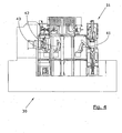
- the pieces of material to be machined constitute the blanks to be transferred to a pressing unit consisting of a machining centre 30 comprising a series of hydraulic presses 31, 32, 33, 34, 35.
- Each individual press can be equipped with the power to guarantee the thrust necessary for the cold extrusion of the blanks and the system for the approach and upward movement of the punch will have an extremely high speed in order to increase the productivity of the machining centre.
- a transfer unit which can consist of a series of manipulator robots 41, 42, 43, 44, 45 comprising steel grippers 50 connected together and powered by a hydraulic, mechanical or compressed-air device as required.
- the individual grippers 50 can transfer each blank from one press to another and, if required by the pressing cycle, rotate the blank at various angles during the transfer.
- the individual stations of the plant consisting of a plurality of presses 30 can be equipped with extraction units, in their lower part near the bed face and near the pressing cylinder.
- These extraction units can consist of small hydraulic linear actuators or another mechanical or pneumatic system as required.
- a mechanical drilling or shearing unit 60 consisting for example, of a vertical mechanical press, working from the bottom upwards or vice versa, as required.
- the punch of this press is designed to eject the transverse section or plug from the blank, which was left by the previous pressing and extrusion stage carried out on the machining centre by the various hydraulic presses.
- the shearing die of this press is designed to eject the excess material from the blank which was left by the previous pressing and extrusion stage carried out on the machining centre.
- the drilling or shearing unit 60 can be equipped with wheels so that it can be moved and applied indifferently to each pressing station from which the hydraulic extraction cylinder can be easily removed.
- the bar in this example of a full rod 10 is then pulled towards a cutting unit, for example consisting of a circular saw 12, which produces sections that can be subsequently processed by the machining centre consisting of a number of hydraulic presses.
- a cutting unit for example consisting of a circular saw 12
- one station 31 of the machining centre consists of a block 14 housing a hydraulic piston 15 which carries out the pressing operation. Inside the hydraulic piston 15 is an extraction piston 16 facing a die bed 17.
- the lower part of the die bed 17 is equipped with an extraction unit 18 designed to move the blanks.
- the blank to be machined 10 is gradually deformed (represented in the figure from left to right) in order to form two longitudinally opposite dead holes 19 separated by a transverse section or plug 20 which can subsequently be removed by means of a drilling unit (not shown in the drawings).
- the plant as described above can easily be adapted to obtain full pieces such as screws, or special shape extruded or pressed products, and to obtain any standard shape extruded or pressed products, whether drilled or sheared, according to machining requirements, which follow the construction specifications dictated by the various international standards for fasteners or fixing systems such as for example the DIN, ISO, ASTM, ANSI/AS JIS and SAE standards, etc., and in general to any mechanical element that can be cold pressed or extruded on the basis of a drawing provided by the customer and with a diameter greater than 30 mm.
Landscapes
- Engineering & Computer Science (AREA)
- Mechanical Engineering (AREA)
- Forging (AREA)
- Press Drives And Press Lines (AREA)
- Adornments (AREA)
- Perforating, Stamping-Out Or Severing By Means Other Than Cutting (AREA)
- Metal Extraction Processes (AREA)
- Extrusion Of Metal (AREA)
- Cell Electrode Carriers And Collectors (AREA)
- Wire Processing (AREA)
- Prostheses (AREA)
- Ultra Sonic Daignosis Equipment (AREA)
- Superconductors And Manufacturing Methods Therefor (AREA)
Claims (18)
- Verfahren zum Kaltverformen von rohrförmigen Metallelementen oder anderen Elementen mit Sackbohrungen oder Durchgangsbohrungen, wie Muttern oder ähnliches, mit einem Durchmesser von größer als 30 mm, wobei die folgenden Bearbeitungsschritte ausgeführt werden:Anordnen und Vorbereiten eines Rohlings (10) aus Rollen oder Stangen eines Vollmaterials aus Metall;Strecken und Abschneiden des Metallmaterials (10) in Werkstücke mit einer bestimmten Länge, falls es sich um einen Rohling in Form einer Rolle handelt;Sequentielles Pressen, indem diese Werkstücke nacheinander durch eine Mehrzahl von Bearbeitungsstationen (31) eines Bearbeitungszentrums geführt werden, welches mehrere hydraulische Pressen umfasst, um ein Rohlingselement mit einer Sackbohrung oder um ein Rohlingselement mit zwei in Längsrichtung gegenüberliegenden Sackbohrungen (19) zu erhalten, die durch einen mittigen quer verlaufenden Abschnitt (20) getrennt sind;Durchbohren des Rohlings und Entfernen des mittig und quer verlaufenden Abschnitts (20), falls das Rohlingselement die beiden in Längsrichtung gegenüberliegenden Sackbohrungen aufweist.
- Verfahren zum Kaltverformen von Metallelementen, wie Standard- und Spezialformschrauben etc., die extrudiert oder gepresst sind, mit einem Durchmesser von größer als 30 mm, mit den folgenden Bearbeitungsschritten:Anordnen und Vorbereiten eines Rohlings (10) aus Rollen oder Stangen eines Vollmaterials aus Metall;Strecken und Abschneiden des Metallmaterials (10) in Werkstücke mit einer bestimmten Länge, falls es sich um einen Rohling in Form einer Rolle handelt;Sequentielles Pressen, indem diese Werkstücke nacheinander durch eine Mehrzahl von Bearbeitungsstationen (31) einer Multi-Hydraulischen-Pressanlage geführt werden, um ein Fertigprodukt (20) zu erhalten, mit oder ohne Späne oder Abfall.
- Verfahren nach einem der Ansprüche 1 oder 2, wobei sich das Anordnen und Vorbereiten des Voll-Rohlings (10) entsprechend dem verwendeten Metallmaterial unterscheidet.
- Verfahren nach Anspruch 3, ausgeführt mit einem Material bestehend aus rostfreiem Stahl, dadurch gekennzeichnet, dass der rostfreie Stahl zu Anfangs mittels Lösungsglühen und Enlegen in eine bezogen auf die Komponenten stöchiometrisch aufeinander abgestimmte Lösung aus Schwefelsäure, Flußsäure, Kaliumpermanganat und Wasserstoffperoxid behandelt wird, sowie anschließend wiederholt gewaschen wird, durch Eintauchen in einen Salztank, um das Pressen zu erleichtern.
- Verfahren nach Anspruch 3, ausgeführt mit einem Material bestehend aus einem niedriglegierten Stahl, dadurch gekennzeichnet, dass dieses Material in Schwefelsäure abgebeizt wird und nachfolgend in einem Phosphorbehälter gewaschen wird, wobei in einer chemischen Reaktion auf der Oberfläche des Werkstücks eine Schicht aus Zinkphosphat ausgebildet wird, im Anschluß daran das Material in einen Natriumstearatbehälter eingetaucht wird, wobei wiederum durch eine chemische Reaktion auf der Oberfläche der vorherigen Schicht aus Zinkphosphat eine dünne Schicht aus Zinkstearat ausgebildet wird.
- Verfahren nach Anspruch 2, dadurch gekennzeichnet dass die Produkte einer Scherung unterworfen werden, zum Beispiel für sechseckige Schraubenköpfe, wobei die Bearbeitung durch eine mechanische Presse erfolgt.
- Verfahren nach einem der Ansprüche 2 bis 6, ausgeführt mit einem Ausgangsmaterial in der Form von Rollen, wobei das zuvor gewaschene Metallmaterial auf einer Drahtstreckmaschine gestreckt wird, die den Strang ausrollt.
- Verfahren nach einem der Ansprüche 2 bis 6, ausgeführt mit einem Ausgangsmaterial in der Form von Stangen, wobei diese Stangen in Bündeln in eine Stangenzerlegemaschine eingelegt werden und wobei die Stangen synchronisiert an der Zerlegestation ankommen, entsprechend den Anforderungen des Bearbeitungszentrums, welches aus den hydraulischen Pressen besteht.
- Verfahren nach Anspruch 7, wobei das freie Ende der Rolle durch einen ersten Satz von Walzen und dann durch ein System von gegenüberliegenden Walzen gezogen wird, so dass der Draht gestreckt wird und zu einer Schneideeinrichtung transportiert wird.
- Verfahren nach einem der Ansprüche 8 oder 9, wobei das Material in Werkstücke mit einer bestimmten Länge geschnitten wird, vorteilhafterweise durch unterschiedliche Verfahren, wie etwa mechanische oder hydraulische Verfahren, mittels eines oder mittels beweglicher Messer oder mittels einer Kreissäge.
- Verfahren nach einem der vorhergehenden Ansprüche, dadurch gekennzeichnet, dass die Anlage oder das Bearbeitungszentrum (30) aus einer Reihe von hydraulischen Pressen unterschiedlicher Größe und unterschiedlicher Leistungsstufen (3134) besteht, die mittels einer Transporteinheit verbunden sind, die vorgesehen ist, um die Werkstücke (10) zu transportieren, die bearbeitet werden sollen.
- Verfahren nach Anspruch 11, dadurch gekennzeichnet, dass die Transporteinheit aus einer Reihe von Greifeinheiten (40-44) besteht, die durch eine geeignete Energiequelle angetrieben sind.
- Verfahren nach einem der vorhergehenden Ansprüche, dadurch gekennzeichnet, dass das Bohren oder Scheren durch eine Spezialeinheit ausgeführt wird, die eine Vertikalpresse umfasst.
- Verfahren nach Anspruch 13, dadurch gekennzeichnet, dass die Vertikalpresse eine mechanische Presse umfasst.
- Verfahren nach einem der vorhergehenden Ansprüche, dadurch gekennzeichnet, dass die Funktionen und die Synchronisation der individuellen Pressen und der Transporteinheit durch eine SPS-Steuerung (PLC) oder einen Mikroprozessor gesteuert werden.
- Anlage zur Durchführung eines Verfahrens nach einem der vorhergehenden Ansprüche, dadurch gekennzeichnet, dass die Anlage eine Reihe von hydraulischen Pressen aufweist, die benachbart zueinander angeordnet sind, und die angeordnet sind, um aufeinanderfolgende Pressschritte an Werkstücken, die zu bearbeiten sind, auszuführen, wobei die Werkstücke von einer Presse zur nächsten Presse transportiert werden, indem geeignete automatische Manipulatoren eingesetzt werden.
- Anlage nach Anspruch 16, dadurch gekennzeichnet, dass diese auch eine Bohrstation oder eine Scherstation umfasst.
- Anlage nach Anspruch 17, dadurch gekennzeichnet, dass diese Bohrstation oder Scherstation eine mechanische Vertikalpresse aufweist.
Applications Claiming Priority (3)
| Application Number | Priority Date | Filing Date | Title |
|---|---|---|---|
| IT000118A ITVR20020118A1 (it) | 2002-11-12 | 2002-11-12 | Procedimento per l'ottenimento di elementi tubolari metallici. |
| ITVR20020118 | 2002-11-12 | ||
| PCT/IT2003/000106 WO2004043626A1 (en) | 2002-11-12 | 2003-02-26 | Methods for the cold extrusion of metallic elements with dead or through holes and plant for carrying out said methods |
Publications (2)
| Publication Number | Publication Date |
|---|---|
| EP1507611A1 EP1507611A1 (de) | 2005-02-23 |
| EP1507611B1 true EP1507611B1 (de) | 2005-11-02 |
Family
ID=32310215
Family Applications (1)
| Application Number | Title | Priority Date | Filing Date |
|---|---|---|---|
| EP03811055A Expired - Lifetime EP1507611B1 (de) | 2002-11-12 | 2003-02-26 | Verfahren zum kaltextrudieren von metallelementen mit sack- oder durchgangslöchern und anlage zur durchführung der verfahren |
Country Status (17)
| Country | Link |
|---|---|
| US (1) | US7347075B2 (de) |
| EP (1) | EP1507611B1 (de) |
| JP (1) | JP2006505412A (de) |
| KR (1) | KR20050058994A (de) |
| CN (1) | CN1329141C (de) |
| AT (1) | ATE308396T1 (de) |
| BR (1) | BR0306817A (de) |
| CA (1) | CA2472817C (de) |
| DE (1) | DE60302154T2 (de) |
| DK (1) | DK1507611T3 (de) |
| ES (1) | ES2252706T3 (de) |
| IT (1) | ITVR20020118A1 (de) |
| MX (1) | MXPA04006746A (de) |
| RU (1) | RU2323061C2 (de) |
| TW (1) | TWI308091B (de) |
| WO (1) | WO2004043626A1 (de) |
| ZA (1) | ZA200405424B (de) |
Cited By (1)
| Publication number | Priority date | Publication date | Assignee | Title |
|---|---|---|---|---|
| CN120055108A (zh) * | 2025-04-28 | 2025-05-30 | 成都航空职业技术学院 | 一种机械工程用具有顶出结构的零配件冲压装置 |
Families Citing this family (25)
| Publication number | Priority date | Publication date | Assignee | Title |
|---|---|---|---|---|
| WO2006061863A1 (en) * | 2004-12-10 | 2006-06-15 | Amafa Service S.R.L. | Press unit provided of multiple dies for obtaining manufactured products |
| US7563335B2 (en) * | 2005-11-07 | 2009-07-21 | Trw Vehicle Safety Systems Inc. | Method of forming a housing of a vehicle occupant protection apparatus |
| RU2315678C2 (ru) * | 2005-11-07 | 2008-01-27 | Бахтерев Сергей Григорьевич | Способ изготовления заготовок для получения полых тонкостенных изделий |
| US20070188562A1 (en) * | 2006-02-15 | 2007-08-16 | Mold-Masters Limited | Heater for a manifold of an injection molding apparatus |
| US8650925B2 (en) | 2007-01-05 | 2014-02-18 | Apple Inc. | Extrusion method for fabricating a compact tube with internal features |
| US8712071B2 (en) * | 2007-01-05 | 2014-04-29 | Apple Inc. | Headset electronics |
| US20080166006A1 (en) | 2007-01-06 | 2008-07-10 | Apple Inc | Light diffuser |
| ATE554517T1 (de) | 2007-01-06 | 2012-05-15 | Apple Inc | Headsetanschluss zur selektiven leitung von signalen je nach der bestimmten ausrichtung des angeschlossenen steckverbinders |
| EP3196551B1 (de) | 2007-01-06 | 2019-05-29 | Apple Inc. | Ohrstöpsel mit mehreren elektrischen kontakten und ohrstöpselsystem mit einem ohrstöpsel und einem ladegerät |
| CN100446889C (zh) * | 2007-04-12 | 2008-12-31 | 林昌绪 | 利用冷镦机加工金属盲管零件的加工方法 |
| ATE462510T1 (de) * | 2008-08-09 | 2010-04-15 | Presswerk Krefeld Gmbh & Co Kg | Verfahren zur herstellung eines gehäuserings |
| DE102009036565B4 (de) * | 2009-08-04 | 2012-02-16 | Wanzke Ag | Maschinensystem zur Steuerung und zum Betrieb mehrerer spanlos formgebender Werkzeugmaschinen |
| US8683842B1 (en) | 2010-03-24 | 2014-04-01 | Norfolk Southern Corporation | Railroad spikes and methods of making the same |
| CN102896271A (zh) * | 2011-07-26 | 2013-01-30 | 锻压制造克雷费尔德有限两合公司 | 制造套环的方法 |
| CN102717231B (zh) * | 2012-05-25 | 2015-06-03 | 重庆极光机械制造有限公司 | 带键套加工工艺 |
| CN102814441B (zh) * | 2012-08-09 | 2015-05-20 | 江苏森威集团飞达股份有限公司 | 一种冷锻方法及冷挤模具 |
| DE102014209009A1 (de) * | 2014-01-27 | 2015-07-30 | Robert Bosch Gmbh | Werkzeugmaschinenvorrichtung |
| US10582284B2 (en) | 2015-09-30 | 2020-03-03 | Apple Inc. | In-ear headphone |
| ES2903138T3 (es) | 2017-12-12 | 2022-03-31 | Nedschroef Herentals N V | Prensa multietapa y procedimiento para la fabricación de una pieza conformada |
| CN110732835B (zh) * | 2018-07-20 | 2021-05-07 | 余姚市飞力机械配件有限公司 | 一种油管接头锁套的生产工艺 |
| CN111842658A (zh) * | 2019-10-23 | 2020-10-30 | 宁波市鄞州风名工业产品设计有限公司 | 数控螺母成型机构 |
| CN111842659A (zh) * | 2019-10-23 | 2020-10-30 | 宁波市鄞州风名工业产品设计有限公司 | 数控多连动螺母成型机构 |
| CN114473371B (zh) * | 2021-12-22 | 2023-05-23 | 马鞍山市申力特重工机械股份有限公司 | 一种剪切机上刀片材料的制备方法及剪切测试设备 |
| CN119588868A (zh) * | 2024-12-12 | 2025-03-11 | 哈尔滨工业大学(威海) | 一种组合脉冲径向加载连续成形装备系统 |
| CN120170429B (zh) * | 2025-05-22 | 2025-08-19 | 浙江裕泰汽车配件有限公司 | 一种底盘挂载焊接套筒及其制作方法 |
Family Cites Families (35)
| Publication number | Priority date | Publication date | Assignee | Title |
|---|---|---|---|---|
| US1714316A (en) * | 1923-07-05 | 1929-05-21 | Bridgeport Brass Co | Method of making nuts or the like |
| US2149578A (en) * | 1938-01-24 | 1939-03-07 | William J Carney | Nut making machine |
| US2272758A (en) * | 1941-02-14 | 1942-02-10 | Waterbury Farrel Foundry Co | Transfer mechanism |
| US2361770A (en) * | 1943-05-28 | 1944-10-31 | Huxon Holding Corp | Manufacture of rivet elements |
| US2689360A (en) * | 1950-02-09 | 1954-09-21 | Ajax Mfg Co | Combined wire drawing and forging machine |
| DE944100C (de) * | 1951-01-16 | 1956-06-07 | Waterbury Farrel Foundry Co | Verfahren und Maschine zum Herstellen polygonaler Muttern |
| US2832973A (en) * | 1956-06-13 | 1958-05-06 | Burdsall & Ward Co | Manufacture of acorn nuts |
| US2871492A (en) | 1956-07-24 | 1959-02-03 | Waterbury Farrel Foundry & Mac | Method of forging a nut blank having a bore with a projecting key |
| NL248062A (de) * | 1959-07-17 | |||
| JPS5147659B1 (de) * | 1971-06-14 | 1976-12-16 | ||
| US4272978A (en) * | 1974-09-03 | 1981-06-16 | Imre Berecz | Progressive stage forging machine |
| DE2501506A1 (de) * | 1975-01-16 | 1976-07-22 | Peltzer & Ehlers | Verfahren zur herstellung von pressteilen aus insbesondere zu einem bund aufgewickeltem drahtmaterial |
| US4048825A (en) * | 1975-12-29 | 1977-09-20 | John Burke Dastrup | Coil re-bar straightener and cutter |
| AT348846B (de) * | 1977-09-26 | 1979-03-12 | Wefoba | Verfahren zur automatischen herstellung von gesenkschmiedeteilen ausgehend von spaltstuecken und vorrichtung zu seiner durchfuehrung |
| US4175417A (en) * | 1977-12-01 | 1979-11-27 | Cassanelli Ernest M | Workpiece forming machine |
| JPS55156635A (en) * | 1979-05-21 | 1980-12-05 | Nitto Seiko Co Ltd | Wire rod defect detecting device in cold forging machine |
| US4291568A (en) * | 1979-08-27 | 1981-09-29 | Veeder Industries Inc. | Method of forming socket wrenches |
| JPS56163047A (en) * | 1980-05-20 | 1981-12-15 | Sumitomo Metal Ind Ltd | Method for lubrication of wire material or bar material |
| IT1129497B (it) * | 1980-12-29 | 1986-06-04 | Teksid Spa | Impianto automatico per stampaggio a caldo e sbavatura di particolari metallici |
| DE3777650D1 (de) * | 1987-09-15 | 1992-04-23 | Sanshin Kogyo Kk | Verfahren und geraet zur herstellung einer hohlzylinderfoermigen lenkrolle fuer magnetische tonbaender. |
| JP2691222B2 (ja) * | 1988-06-14 | 1997-12-17 | 株式会社万陽 | 棒鋼切断機におけるビレットの切断方法、及びその重量計測装置 |
| SU1708485A1 (ru) * | 1989-07-18 | 1992-01-30 | Научно-Производственное Объединение По Кузнечно-Прессовому Оборудованию И Гибким Производственным Системам Для Обработки Давлением "Эникмаш" | Способ холодной штамповки заготовок шестигранных гаек |
| JPH03193823A (ja) * | 1989-12-22 | 1991-08-23 | Daido Steel Co Ltd | 構造用ステンレス鋼高力ボルトの製造方法 |
| US5354383A (en) * | 1991-03-29 | 1994-10-11 | Itb, S.R.L. | Process for pickling and passivating stainless steel without using nitric acid |
| JPH0829390B2 (ja) * | 1993-06-01 | 1996-03-27 | 株式会社アイピーシー | エアコン用アルミスクロールの連続生産方法 |
| JPH07108340A (ja) * | 1993-10-13 | 1995-04-25 | Sumitomo Metal Ind Ltd | コロ軸受ベアリングレース用粗形材の製造方法 |
| JP3226199B2 (ja) * | 1994-12-22 | 2001-11-05 | 株式会社栗本鐵工所 | オーステナイト系ステンレス鋼製の六角ボルト |
| US5632175A (en) * | 1995-10-27 | 1997-05-27 | Green; Paul O. | Rebar fabricating apparatus |
| JPH09323198A (ja) * | 1996-06-04 | 1997-12-16 | Nippon Steel Corp | アルミサッシ用プレス加工機 |
| JPH11256374A (ja) * | 1997-07-08 | 1999-09-21 | Aichi Steel Works Ltd | ステンレス鋼及びチタン用酸洗処理液及びその酸洗処理方法 |
| IT1295500B1 (it) | 1997-10-21 | 1999-05-12 | Pierangelo Girardello | Procedimento per la lavorazione dei metalli e prodotto ottenuto con detto procedimento. |
| US6571452B1 (en) * | 1999-01-19 | 2003-06-03 | Barsplice Products, Inc. | Method of making steel couplers for joining concrete reinforcing bars |
| JP2000237839A (ja) * | 1999-02-19 | 2000-09-05 | Nippon Koshuha Steel Co Ltd | 鍔付環状部材の製造方法 |
| US6293164B1 (en) * | 1999-06-30 | 2001-09-25 | Trw Inc. | Rack and pinion steering apparatus and method for manufacturing a helical pinion |
| JP3931729B2 (ja) * | 2002-01-24 | 2007-06-20 | 日産自動車株式会社 | 組立式カムシャフト用カムピースの製造方法 |
-
2002
- 2002-11-12 IT IT000118A patent/ITVR20020118A1/it unknown
-
2003
- 2003-02-26 CN CNB038082616A patent/CN1329141C/zh not_active Expired - Fee Related
- 2003-02-26 BR BR0306817-0A patent/BR0306817A/pt not_active IP Right Cessation
- 2003-02-26 JP JP2004551156A patent/JP2006505412A/ja active Pending
- 2003-02-26 RU RU2004121678/02A patent/RU2323061C2/ru not_active IP Right Cessation
- 2003-02-26 AT AT03811055T patent/ATE308396T1/de active
- 2003-02-26 KR KR1020047010849A patent/KR20050058994A/ko not_active Ceased
- 2003-02-26 CA CA2472817A patent/CA2472817C/en not_active Expired - Fee Related
- 2003-02-26 EP EP03811055A patent/EP1507611B1/de not_active Expired - Lifetime
- 2003-02-26 DE DE60302154T patent/DE60302154T2/de not_active Expired - Lifetime
- 2003-02-26 WO PCT/IT2003/000106 patent/WO2004043626A1/en not_active Ceased
- 2003-02-26 MX MXPA04006746A patent/MXPA04006746A/es active IP Right Grant
- 2003-02-26 DK DK03811055T patent/DK1507611T3/da active
- 2003-02-26 ES ES03811055T patent/ES2252706T3/es not_active Expired - Lifetime
- 2003-02-26 US US10/501,104 patent/US7347075B2/en not_active Expired - Fee Related
- 2003-11-11 TW TW092131447A patent/TWI308091B/zh not_active IP Right Cessation
-
2004
- 2004-07-08 ZA ZA200405424A patent/ZA200405424B/xx unknown
Cited By (1)
| Publication number | Priority date | Publication date | Assignee | Title |
|---|---|---|---|---|
| CN120055108A (zh) * | 2025-04-28 | 2025-05-30 | 成都航空职业技术学院 | 一种机械工程用具有顶出结构的零配件冲压装置 |
Also Published As
| Publication number | Publication date |
|---|---|
| AU2003215906A1 (en) | 2004-06-03 |
| DE60302154T2 (de) | 2006-07-20 |
| CA2472817A1 (en) | 2004-05-27 |
| CA2472817C (en) | 2011-08-30 |
| RU2004121678A (ru) | 2005-05-10 |
| BR0306817A (pt) | 2004-12-28 |
| MXPA04006746A (es) | 2005-09-08 |
| ZA200405424B (en) | 2004-11-08 |
| US7347075B2 (en) | 2008-03-25 |
| EP1507611A1 (de) | 2005-02-23 |
| DK1507611T3 (da) | 2006-03-20 |
| TWI308091B (en) | 2009-04-01 |
| KR20050058994A (ko) | 2005-06-17 |
| ES2252706T3 (es) | 2006-05-16 |
| JP2006505412A (ja) | 2006-02-16 |
| DE60302154D1 (de) | 2005-12-08 |
| ATE308396T1 (de) | 2005-11-15 |
| WO2004043626A1 (en) | 2004-05-27 |
| TW200413119A (en) | 2004-08-01 |
| ITVR20020118A1 (it) | 2004-05-13 |
| CN1646244A (zh) | 2005-07-27 |
| US20050145004A1 (en) | 2005-07-07 |
| RU2323061C2 (ru) | 2008-04-27 |
| CN1329141C (zh) | 2007-08-01 |
Similar Documents
| Publication | Publication Date | Title |
|---|---|---|
| US7347075B2 (en) | Methods for the cold extrusion of metallic elements with dead or through holes and plant for carrying out said methods | |
| EP3854517A1 (de) | Neuartiges verfahren zur herstellung von hohlwellen | |
| CN107186450A (zh) | 汽车cvt自动变速器行星架承板制造工艺 | |
| CN103157758A (zh) | 行星减速器内齿环精锻塑性成型工艺 | |
| CN106623467A (zh) | 一种加工喷雾机轴的冷挤压机及喷雾机轴的加工工艺 | |
| JP4601736B2 (ja) | 金属加工方法 | |
| AU2003215906B2 (en) | Methods for the cold extrusion of metallic elements with dead or through holes and plant for carrying out said methods | |
| CN202606536U (zh) | 生产齿条的设备系统 | |
| CN111203453A (zh) | 一种小口径ta18钛合金无缝管生产的方法 | |
| US6474127B1 (en) | Pressing method, in particular for obtaining hydraulic cylinders and high-pressure filters | |
| CN206474519U (zh) | 一种加工喷雾机轴的冷挤压机 | |
| CN106334906A (zh) | 一种汽车零部件表面加工方法 | |
| KR20160077008A (ko) | 플루이드 엔드 및 기타 공작물을 위한 순형상 단조 | |
| CN215786086U (zh) | 一种防变形冲孔装置 | |
| RU2133664C1 (ru) | Способ изготовления детали с отростками | |
| DE10156034A1 (de) | Anordnung zur Herstellung von Profilen und Blechformteilen | |
| JP2567779B2 (ja) | 汎用プレス機によるキャタピラ用トラックリング加工法 | |
| WO2006061863A1 (en) | Press unit provided of multiple dies for obtaining manufactured products | |
| CN116944805A (zh) | 一种多弧离子钛靶材的加工工艺方法 | |
| RU2320769C1 (ru) | Способ обработки металлических материалов | |
| CN114160727A (zh) | 一种大型四爪吊钩类锻件锻造方法 | |
| Beisel | Cold Extrusion—Pre-Programmed Efficiency? | |
| CN110695614A (zh) | 汽车扭力梁横梁下板冷冲压生产工艺 | |
| Barve | Special Machines for Forging | |
| DE3512553A1 (de) | Verfahren zur herstellung von warmgewalzten kegelraedern |
Legal Events
| Date | Code | Title | Description |
|---|---|---|---|
| PUAI | Public reference made under article 153(3) epc to a published international application that has entered the european phase |
Free format text: ORIGINAL CODE: 0009012 |
|
| 17P | Request for examination filed |
Effective date: 20040729 |
|
| AK | Designated contracting states |
Kind code of ref document: A1 Designated state(s): AT BE BG CH CY CZ DE DK EE ES FI FR GB GR HU IE IT LI LU MC NL PT SE SI SK TR |
|
| AX | Request for extension of the european patent |
Extension state: AL LT LV MK RO |
|
| 17Q | First examination report despatched |
Effective date: 20050124 |
|
| GRAP | Despatch of communication of intention to grant a patent |
Free format text: ORIGINAL CODE: EPIDOSNIGR1 |
|
| REG | Reference to a national code |
Ref country code: HK Ref legal event code: DE Ref document number: 1071100 Country of ref document: HK |
|
| GRAS | Grant fee paid |
Free format text: ORIGINAL CODE: EPIDOSNIGR3 |
|
| GRAA | (expected) grant |
Free format text: ORIGINAL CODE: 0009210 |
|
| AK | Designated contracting states |
Kind code of ref document: B1 Designated state(s): AT BE BG CH CY CZ DE DK EE ES FI FR GB GR HU IE IT LI LU MC NL PT SE SI SK TR |
|
| AX | Request for extension of the european patent |
Extension state: AL LT LV MK RO |
|
| PG25 | Lapsed in a contracting state [announced via postgrant information from national office to epo] |
Ref country code: FI Free format text: LAPSE BECAUSE OF FAILURE TO SUBMIT A TRANSLATION OF THE DESCRIPTION OR TO PAY THE FEE WITHIN THE PRESCRIBED TIME-LIMIT Effective date: 20051102 Ref country code: SK Free format text: LAPSE BECAUSE OF FAILURE TO SUBMIT A TRANSLATION OF THE DESCRIPTION OR TO PAY THE FEE WITHIN THE PRESCRIBED TIME-LIMIT Effective date: 20051102 Ref country code: SI Free format text: LAPSE BECAUSE OF FAILURE TO SUBMIT A TRANSLATION OF THE DESCRIPTION OR TO PAY THE FEE WITHIN THE PRESCRIBED TIME-LIMIT Effective date: 20051102 |
|
| REG | Reference to a national code |
Ref country code: GB Ref legal event code: FG4D |
|
| REG | Reference to a national code |
Ref country code: CH Ref legal event code: EP |
|
| REF | Corresponds to: |
Ref document number: 60302154 Country of ref document: DE Date of ref document: 20051208 Kind code of ref document: P |
|
| PG25 | Lapsed in a contracting state [announced via postgrant information from national office to epo] |
Ref country code: GR Free format text: LAPSE BECAUSE OF FAILURE TO SUBMIT A TRANSLATION OF THE DESCRIPTION OR TO PAY THE FEE WITHIN THE PRESCRIBED TIME-LIMIT Effective date: 20060202 Ref country code: BG Free format text: LAPSE BECAUSE OF FAILURE TO SUBMIT A TRANSLATION OF THE DESCRIPTION OR TO PAY THE FEE WITHIN THE PRESCRIBED TIME-LIMIT Effective date: 20060202 |
|
| REG | Reference to a national code |
Ref country code: SE Ref legal event code: TRGR |
|
| PG25 | Lapsed in a contracting state [announced via postgrant information from national office to epo] |
Ref country code: LU Free format text: LAPSE BECAUSE OF NON-PAYMENT OF DUE FEES Effective date: 20060228 Ref country code: MC Free format text: LAPSE BECAUSE OF NON-PAYMENT OF DUE FEES Effective date: 20060228 |
|
| REG | Reference to a national code |
Ref country code: CH Ref legal event code: NV Representative=s name: WILLIAM BLANC & CIE CONSEILS EN PROPRIETE INDUSTRI |
|
| DAX | Request for extension of the european patent (deleted) | ||
| REG | Reference to a national code |
Ref country code: DK Ref legal event code: T3 |
|
| PG25 | Lapsed in a contracting state [announced via postgrant information from national office to epo] |
Ref country code: PT Free format text: LAPSE BECAUSE OF FAILURE TO SUBMIT A TRANSLATION OF THE DESCRIPTION OR TO PAY THE FEE WITHIN THE PRESCRIBED TIME-LIMIT Effective date: 20060403 |
|
| PG25 | Lapsed in a contracting state [announced via postgrant information from national office to epo] |
Ref country code: HU Free format text: LAPSE BECAUSE OF FAILURE TO SUBMIT A TRANSLATION OF THE DESCRIPTION OR TO PAY THE FEE WITHIN THE PRESCRIBED TIME-LIMIT Effective date: 20060503 |
|
| REG | Reference to a national code |
Ref country code: ES Ref legal event code: FG2A Ref document number: 2252706 Country of ref document: ES Kind code of ref document: T3 |
|
| ET | Fr: translation filed | ||
| PLBE | No opposition filed within time limit |
Free format text: ORIGINAL CODE: 0009261 |
|
| STAA | Information on the status of an ep patent application or granted ep patent |
Free format text: STATUS: NO OPPOSITION FILED WITHIN TIME LIMIT |
|
| 26N | No opposition filed |
Effective date: 20060803 |
|
| PG25 | Lapsed in a contracting state [announced via postgrant information from national office to epo] |
Ref country code: EE Free format text: LAPSE BECAUSE OF FAILURE TO SUBMIT A TRANSLATION OF THE DESCRIPTION OR TO PAY THE FEE WITHIN THE PRESCRIBED TIME-LIMIT Effective date: 20051102 |
|
| PG25 | Lapsed in a contracting state [announced via postgrant information from national office to epo] |
Ref country code: CY Free format text: LAPSE BECAUSE OF FAILURE TO SUBMIT A TRANSLATION OF THE DESCRIPTION OR TO PAY THE FEE WITHIN THE PRESCRIBED TIME-LIMIT Effective date: 20051102 |
|
| REG | Reference to a national code |
Ref country code: CH Ref legal event code: PFA Owner name: AMAFA SERVICE SRL. Free format text: AMAFA SERVICE SRL.#VIA LAZZARETI, 2/A#42100 REGGIO EMILIA (IT) -TRANSFER TO- AMAFA SERVICE SRL.#VIA LAZZARETI, 2/A#42100 REGGIO EMILIA (IT) |
|
| PGFP | Annual fee paid to national office [announced via postgrant information from national office to epo] |
Ref country code: IE Payment date: 20110225 Year of fee payment: 9 Ref country code: DK Payment date: 20110221 Year of fee payment: 9 |
|
| PGFP | Annual fee paid to national office [announced via postgrant information from national office to epo] |
Ref country code: AT Payment date: 20110207 Year of fee payment: 9 Ref country code: CZ Payment date: 20110119 Year of fee payment: 9 Ref country code: CH Payment date: 20110125 Year of fee payment: 9 Ref country code: DE Payment date: 20110118 Year of fee payment: 9 Ref country code: TR Payment date: 20110221 Year of fee payment: 9 Ref country code: SE Payment date: 20110217 Year of fee payment: 9 Ref country code: FR Payment date: 20110316 Year of fee payment: 9 Ref country code: NL Payment date: 20110131 Year of fee payment: 9 Ref country code: IT Payment date: 20110217 Year of fee payment: 9 |
|
| REG | Reference to a national code |
Ref country code: CH Ref legal event code: PCAR Free format text: NOVAGRAAF SWITZERLAND SA;CHEMIN DE L'ECHO 3;1213 ONEX (CH) |
|
| PGFP | Annual fee paid to national office [announced via postgrant information from national office to epo] |
Ref country code: BE Payment date: 20110204 Year of fee payment: 9 Ref country code: GB Payment date: 20110223 Year of fee payment: 9 Ref country code: ES Payment date: 20110221 Year of fee payment: 9 |
|
| REG | Reference to a national code |
Ref country code: HK Ref legal event code: WD Ref document number: 1071100 Country of ref document: HK |
|
| BERE | Be: lapsed |
Owner name: *AMAFA SERVICE S.R.L. Effective date: 20120228 |
|
| REG | Reference to a national code |
Ref country code: NL Ref legal event code: V1 Effective date: 20120901 |
|
| REG | Reference to a national code |
Ref country code: CH Ref legal event code: PL |
|
| GBPC | Gb: european patent ceased through non-payment of renewal fee |
Effective date: 20120226 |
|
| PG25 | Lapsed in a contracting state [announced via postgrant information from national office to epo] |
Ref country code: CH Free format text: LAPSE BECAUSE OF NON-PAYMENT OF DUE FEES Effective date: 20120229 Ref country code: LI Free format text: LAPSE BECAUSE OF NON-PAYMENT OF DUE FEES Effective date: 20120229 Ref country code: SE Free format text: LAPSE BECAUSE OF NON-PAYMENT OF DUE FEES Effective date: 20120227 Ref country code: CZ Free format text: LAPSE BECAUSE OF NON-PAYMENT OF DUE FEES Effective date: 20120226 |
|
| REG | Reference to a national code |
Ref country code: DK Ref legal event code: EBP |
|
| REG | Reference to a national code |
Ref country code: IE Ref legal event code: MM4A |
|
| REG | Reference to a national code |
Ref country code: FR Ref legal event code: ST Effective date: 20121031 |
|
| PG25 | Lapsed in a contracting state [announced via postgrant information from national office to epo] |
Ref country code: IT Free format text: LAPSE BECAUSE OF NON-PAYMENT OF DUE FEES Effective date: 20120226 |
|
| REG | Reference to a national code |
Ref country code: AT Ref legal event code: MM01 Ref document number: 308396 Country of ref document: AT Kind code of ref document: T Effective date: 20120226 |
|
| REG | Reference to a national code |
Ref country code: DE Ref legal event code: R119 Ref document number: 60302154 Country of ref document: DE Effective date: 20120901 |
|
| PG25 | Lapsed in a contracting state [announced via postgrant information from national office to epo] |
Ref country code: BE Free format text: LAPSE BECAUSE OF NON-PAYMENT OF DUE FEES Effective date: 20120228 |
|
| PG25 | Lapsed in a contracting state [announced via postgrant information from national office to epo] |
Ref country code: FR Free format text: LAPSE BECAUSE OF NON-PAYMENT OF DUE FEES Effective date: 20120229 Ref country code: GB Free format text: LAPSE BECAUSE OF NON-PAYMENT OF DUE FEES Effective date: 20120226 Ref country code: NL Free format text: LAPSE BECAUSE OF NON-PAYMENT OF DUE FEES Effective date: 20120901 Ref country code: IE Free format text: LAPSE BECAUSE OF NON-PAYMENT OF DUE FEES Effective date: 20120226 Ref country code: AT Free format text: LAPSE BECAUSE OF NON-PAYMENT OF DUE FEES Effective date: 20120226 |
|
| PG25 | Lapsed in a contracting state [announced via postgrant information from national office to epo] |
Ref country code: DE Free format text: LAPSE BECAUSE OF NON-PAYMENT OF DUE FEES Effective date: 20120901 |
|
| REG | Reference to a national code |
Ref country code: ES Ref legal event code: FD2A Effective date: 20130708 |
|
| PG25 | Lapsed in a contracting state [announced via postgrant information from national office to epo] |
Ref country code: ES Free format text: LAPSE BECAUSE OF NON-PAYMENT OF DUE FEES Effective date: 20120227 |
|
| PG25 | Lapsed in a contracting state [announced via postgrant information from national office to epo] |
Ref country code: DK Free format text: LAPSE BECAUSE OF NON-PAYMENT OF DUE FEES Effective date: 20120229 |
|
| PG25 | Lapsed in a contracting state [announced via postgrant information from national office to epo] |
Ref country code: TR Free format text: LAPSE BECAUSE OF NON-PAYMENT OF DUE FEES Effective date: 20120226 |